EP2871620B1 - Rauchdetektionsanordnung - Google Patents
Rauchdetektionsanordnung Download PDFInfo
- Publication number
- EP2871620B1 EP2871620B1 EP14191904.3A EP14191904A EP2871620B1 EP 2871620 B1 EP2871620 B1 EP 2871620B1 EP 14191904 A EP14191904 A EP 14191904A EP 2871620 B1 EP2871620 B1 EP 2871620B1
- Authority
- EP
- European Patent Office
- Prior art keywords
- piston
- purging
- valve
- aspiration
- opening
- Prior art date
- Legal status (The legal status is an assumption and is not a legal conclusion. Google has not performed a legal analysis and makes no representation as to the accuracy of the status listed.)
- Active
Links
- 238000001514 detection method Methods 0.000 title claims description 98
- 239000000779 smoke Substances 0.000 title claims description 39
- 238000009423 ventilation Methods 0.000 claims description 41
- 238000001035 drying Methods 0.000 claims description 6
- 239000002245 particle Substances 0.000 claims description 6
- 230000006835 compression Effects 0.000 claims description 5
- 238000007906 compression Methods 0.000 claims description 5
- 230000007704 transition Effects 0.000 claims description 4
- 238000001816 cooling Methods 0.000 claims description 2
- 238000010926 purge Methods 0.000 claims 26
- 239000003570 air Substances 0.000 description 42
- UGFAIRIUMAVXCW-UHFFFAOYSA-N Carbon monoxide Chemical compound [O+]#[C-] UGFAIRIUMAVXCW-UHFFFAOYSA-N 0.000 description 8
- 238000007664 blowing Methods 0.000 description 8
- 239000003546 flue gas Substances 0.000 description 8
- 239000007789 gas Substances 0.000 description 8
- 230000000903 blocking effect Effects 0.000 description 6
- 238000006073 displacement reaction Methods 0.000 description 5
- 239000000428 dust Substances 0.000 description 4
- 238000007789 sealing Methods 0.000 description 3
- 239000000470 constituent Substances 0.000 description 2
- 238000010276 construction Methods 0.000 description 2
- 238000013461 design Methods 0.000 description 2
- 230000000694 effects Effects 0.000 description 2
- 238000004519 manufacturing process Methods 0.000 description 2
- 230000004913 activation Effects 0.000 description 1
- 239000012080 ambient air Substances 0.000 description 1
- 230000008901 benefit Effects 0.000 description 1
- 230000008859 change Effects 0.000 description 1
- 238000004140 cleaning Methods 0.000 description 1
- 239000013013 elastic material Substances 0.000 description 1
- 239000012530 fluid Substances 0.000 description 1
- 239000012535 impurity Substances 0.000 description 1
- 238000005259 measurement Methods 0.000 description 1
- 238000000034 method Methods 0.000 description 1
- 238000012544 monitoring process Methods 0.000 description 1
- 230000008569 process Effects 0.000 description 1
- 238000012545 processing Methods 0.000 description 1
- 230000009467 reduction Effects 0.000 description 1
- 238000000926 separation method Methods 0.000 description 1
- 238000007493 shaping process Methods 0.000 description 1
Images


Classifications
-
- G—PHYSICS
- G08—SIGNALLING
- G08B—SIGNALLING OR CALLING SYSTEMS; ORDER TELEGRAPHS; ALARM SYSTEMS
- G08B17/00—Fire alarms; Alarms responsive to explosion
- G08B17/10—Actuation by presence of smoke or gases, e.g. automatic alarm devices for analysing flowing fluid materials by the use of optical means
-
- B—PERFORMING OPERATIONS; TRANSPORTING
- B08—CLEANING
- B08B—CLEANING IN GENERAL; PREVENTION OF FOULING IN GENERAL
- B08B5/00—Cleaning by methods involving the use of air flow or gas flow
- B08B5/02—Cleaning by the force of jets, e.g. blowing-out cavities
-
- F—MECHANICAL ENGINEERING; LIGHTING; HEATING; WEAPONS; BLASTING
- F16—ENGINEERING ELEMENTS AND UNITS; GENERAL MEASURES FOR PRODUCING AND MAINTAINING EFFECTIVE FUNCTIONING OF MACHINES OR INSTALLATIONS; THERMAL INSULATION IN GENERAL
- F16K—VALVES; TAPS; COCKS; ACTUATING-FLOATS; DEVICES FOR VENTING OR AERATING
- F16K3/00—Gate valves or sliding valves, i.e. cut-off apparatus with closing members having a sliding movement along the seat for opening and closing
- F16K3/22—Gate valves or sliding valves, i.e. cut-off apparatus with closing members having a sliding movement along the seat for opening and closing with sealing faces shaped as surfaces of solids of revolution
- F16K3/24—Gate valves or sliding valves, i.e. cut-off apparatus with closing members having a sliding movement along the seat for opening and closing with sealing faces shaped as surfaces of solids of revolution with cylindrical valve members
- F16K3/26—Gate valves or sliding valves, i.e. cut-off apparatus with closing members having a sliding movement along the seat for opening and closing with sealing faces shaped as surfaces of solids of revolution with cylindrical valve members with fluid passages in the valve member
- F16K3/262—Gate valves or sliding valves, i.e. cut-off apparatus with closing members having a sliding movement along the seat for opening and closing with sealing faces shaped as surfaces of solids of revolution with cylindrical valve members with fluid passages in the valve member with a transverse bore in the valve member
-
- G—PHYSICS
- G01—MEASURING; TESTING
- G01N—INVESTIGATING OR ANALYSING MATERIALS BY DETERMINING THEIR CHEMICAL OR PHYSICAL PROPERTIES
- G01N33/00—Investigating or analysing materials by specific methods not covered by groups G01N1/00 - G01N31/00
- G01N33/0004—Gaseous mixtures, e.g. polluted air
- G01N33/0009—General constructional details of gas analysers, e.g. portable test equipment
- G01N33/0027—General constructional details of gas analysers, e.g. portable test equipment concerning the detector
- G01N33/0029—Cleaning of the detector
-
- G—PHYSICS
- G08—SIGNALLING
- G08B—SIGNALLING OR CALLING SYSTEMS; ORDER TELEGRAPHS; ALARM SYSTEMS
- G08B17/00—Fire alarms; Alarms responsive to explosion
- G08B17/10—Actuation by presence of smoke or gases, e.g. automatic alarm devices for analysing flowing fluid materials by the use of optical means
- G08B17/103—Actuation by presence of smoke or gases, e.g. automatic alarm devices for analysing flowing fluid materials by the use of optical means using a light emitting and receiving device
- G08B17/107—Actuation by presence of smoke or gases, e.g. automatic alarm devices for analysing flowing fluid materials by the use of optical means using a light emitting and receiving device for detecting light-scattering due to smoke
-
- G—PHYSICS
- G08—SIGNALLING
- G08B—SIGNALLING OR CALLING SYSTEMS; ORDER TELEGRAPHS; ALARM SYSTEMS
- G08B29/00—Checking or monitoring of signalling or alarm systems; Prevention or correction of operating errors, e.g. preventing unauthorised operation
-
- B—PERFORMING OPERATIONS; TRANSPORTING
- B08—CLEANING
- B08B—CLEANING IN GENERAL; PREVENTION OF FOULING IN GENERAL
- B08B9/00—Cleaning hollow articles by methods or apparatus specially adapted thereto
-
- G—PHYSICS
- G01—MEASURING; TESTING
- G01N—INVESTIGATING OR ANALYSING MATERIALS BY DETERMINING THEIR CHEMICAL OR PHYSICAL PROPERTIES
- G01N1/00—Sampling; Preparing specimens for investigation
- G01N1/02—Devices for withdrawing samples
- G01N1/22—Devices for withdrawing samples in the gaseous state
- G01N1/26—Devices for withdrawing samples in the gaseous state with provision for intake from several spaces
-
- G—PHYSICS
- G01—MEASURING; TESTING
- G01N—INVESTIGATING OR ANALYSING MATERIALS BY DETERMINING THEIR CHEMICAL OR PHYSICAL PROPERTIES
- G01N15/00—Investigating characteristics of particles; Investigating permeability, pore-volume or surface-area of porous materials
- G01N2015/0042—Investigating dispersion of solids
- G01N2015/0046—Investigating dispersion of solids in gas, e.g. smoke
-
- G—PHYSICS
- G08—SIGNALLING
- G08B—SIGNALLING OR CALLING SYSTEMS; ORDER TELEGRAPHS; ALARM SYSTEMS
- G08B17/00—Fire alarms; Alarms responsive to explosion
- G08B17/10—Actuation by presence of smoke or gases, e.g. automatic alarm devices for analysing flowing fluid materials by the use of optical means
- G08B17/11—Actuation by presence of smoke or gases, e.g. automatic alarm devices for analysing flowing fluid materials by the use of optical means using an ionisation chamber for detecting smoke or gas
- G08B17/113—Constructional details
Definitions
- the invention relates to a smoke detection arrangement for the detection of flue gas or smoke particles in the air of a building, comprising an intake system for generating a negative pressure, an intake pipe via which the piping system is connected to the intake system, a detection device connected to the intake system and / or the intake pipe in order to detect flue gas in the gaseous medium aspirated from the pipeline system, a blow-off device with a positive pressure source for introducing a gaseous medium into the suction line, wherein a valve is provided, via which a connection of the overpressure source to the suction line can be opened or closed.
- Smoke detection arrangements are known for a long time and refer to the prior art in different embodiments.
- smoke detection arrangements For the monitoring of buildings smoke detection arrangements are used, in which samples are taken from the room via a piping system, which are supplied to a detection device.
- This detection device is adapted to components of the gaseous medium, in particular the air, too analyze to detect smoke gases. Thus, there is an early detection of a possible fire in the building.
- the document DE 2008 006811 U1 indicates the use of several valves per line, which are controlled separately and with much technical effort.
- smoke detection arrangements are preferably used which continuously suck in a partial mass flow from the building and supply it to the detection apparatus.
- the aspirated medium also contains particles, such as dust, which subsequently deposit in the smoke detection arrangement and, in the worst case, impair the function of the detection device.
- filters are used in front of the detection device to prevent the ingress of dust into the detection device.
- another problem arises, namely, that the suction line, which directs the sub-mass flow to the detection device is routed through these particles. For this reason, blow-out devices are used.
- Blow-off devices include an overpressure source, such as a compressor or buffer, from which a gaseous medium is jetted into the suction line to blow it free.
- an overpressure source such as a compressor or buffer
- the suction line must be separated from the detection device in order to avoid that the compressed air or the pressure surge damage the detection device.
- a solenoid valve which separates the suction line from the detection device.
- a control is necessary, which closes in a first step, the magnetic valve to protect the detection device and in a second step, the connection of the pressure source opens with the suction to cause the blowing out.
- simple control devices are provided according to the prior art. Disadvantage of this design is that two solenoid valves and a controller must be provided.
- Generic smoke detection arrangements are usually arranged in hard to reach places where, moreover, little space is available. Furthermore, these detection arrangements must preferably be maintenance-free and reliable function.
- the object of the invention is therefore to provide a smoke detection arrangement which operates reliably and substantially maintenance-free, and which is also inexpensive to manufacture and compact.
- the smoke detection arrangement for the detection of flue gas and / or smoke particles in the air of a building, comprising an intake system for the intake of air via a piping system, a suction pipe, via which the piping system is connected to the intake system, a detection device connected to the intake system and / or the suction duct is connected to detect flue gas in the air sucked from the piping system, a blow-off device with a positive pressure source for introducing a gaseous medium into the suction line, wherein a valve is provided, via which a connection of the overpressure source opens with the suction line or can be closed, are that the valve has an intake position in which the detection device is connected to the intake system and the intake pipe, that the valve has a free-flow position, in which the detection device is separated from the suction line u nd in which the overpressure source is connected to the suction line, and that, when an overpressure from the overpressure source acts on the valve, the valve, driven by the gaseous medium of the overpressure source
- the invention can be configured such that the valve between the bladder position and the suction position has a blocking position in which the overpressure source, the detection device and the suction line are separated from each other, that the valve has a piston in a valve housing from the intake position in the free-float position is movable, that the valve housing has a piston opening whose profile substantially corresponds to the profile of the piston, so that it is guided in the piston opening and that preferably the piston gap between piston opening and piston is substantially sealed, wherein the piston is optionally linearly guided in the valve housing, that the piston comprises a ventilation duct which extends substantially transverse to the movement axis and enters the piston at a first location of the lateral surface and exits at a second location of the lateral surface, so that the piston through the ventilation duct is interspersed that the valve housing comprises a first vent opening and a second vent opening and that in the intake position of the valve, the first vent opening is connected via the vent channel of the piston with the second vent opening, that the piston comprises a free-flow channel extending
- the invention can be configured such that between the ventilation duct at the first location of the lateral surface of the piston and the free-air channel at the third location of the lateral surface of the piston, a web is provided through which the first vent opening in the blocking position, in particular during the transition from the Suction in the clear position, is closed, that on the second end face of the piston, a pressure medium, preferably an elastic body such as a compression spring, is provided, which acts in particular in the clearing position against the second end face of the piston, and that the pressure force of the pressure medium is lower in the suction position, as acting on the first end side by the pressure source pressure force, so that the piston moves with applied pressure force of the overpressure source in the bluff position and / or is in the bluff position, and / or that on the first end face of the piston acting Dru ck of the gaseous medium of the overpressure source is greater than the pressure of the gaseous medium in the blast line, that the pressure of the gaseous medium for blowing out the suction line in the valve
- the invention can be configured such that the intake system continuously conveys air and possibly flue gas contained in the air into the detection device in order to enable continuous flue gas detection that a filter, a drying device, a cooling device or similar components are provided in the intake region of the detection device in that the air conducted into the detection device is conducted back into the pipeline system via a return line, that the components valve, detection device and / or intake system are arranged as a unit in a housing, and / or that the piston is designed as a round, in particular cylindrical piston is, which is guided movably along its axis of rotation, but is secured against rotation.
- the device or arrangement according to the invention may be designed such that a pipeline system extends into different regions and / or rooms of a building, that air samples are taken from different areas of the building via this pipeline system and / or that the latter is routed to a central detection system
- Piping system is optionally configured branched, preferably extending individual branches of the piping system in different areas and / or rooms of a building.
- the piping system corresponds to the piping of a central ventilation system or a piping system specially designed for the detection of smoke constituents.
- a recess or bore running along the axis of movement into the piston is provided on the first end face of the piston, which forms at least a part of the free-jet channel, that a blow-off tube is provided which extends from the housing along the axis of movement in the piston opening and at the free end of the free-blowing opening is provided so that coming from the overpressure source gaseous medium through the Free-blown tube and the blast free opening can be passed towards the piston, and that the blow-off tube protrudes into the recess in the intake position.
- the smoke detection arrangement according to the invention has an intake system with a suction line.
- the intake system is suitable and / or designed to generate a negative pressure and / or to convey the gaseous medium or the air of the building to the detection device.
- the detection device is connected via the suction line to the piping system.
- further components such as a filter, a drying device and / or other means for processing the gaseous medium to be detected are provided in the area in front of the detection device.
- the intake system may be a conventional blower provided before or after the detection device for sucking the air out of the piping system.
- gas treatment components eg dryer, heater, filter, etc.
- these components may be provided in the flow direction before or after the valve. In an arrangement in front of the valve when blowing out the gas also flows through the gas treatment components. As a result, these components can be cleaned when blowing out.
- an overpressure source according to the invention is provided, which is connectable to the suction line. This connection is done in particular via the valve according to the invention.
- the overpressure source or the gaseous medium discharged from the overpressure source for blowing out the suction line has a pressure which is greater than the pressure in the suction line. This ensures that the medium of the overpressure source blows the line.
- the pressure of the medium of the overpressure source is greater than the pressure in the piping system and greater than the ambient pressure.
- the gaseous medium of the overpressure source is moved into the suction line against the suction direction and the suction line is blown free.
- the gaseous medium of the overpressure source is passed through the suction line in the piping system.
- the suction direction is the flow direction of the air of the piping system in the suction line, which is adjusted when the intake system promotes the air in the intake pipe to the detection device.
- the pressure of the overpressure source is more than 2, 3, 4, 5, 6, 7, or 8 bar, preferably about 8 bar.
- the valve according to the invention is designed such that the connection between the suction line and the detection device is automatically closed when the overpressure source acts on the valve. On the other hand, if the overpressure source does not act on the valve, it automatically switches to a position in which the intake line is connected to the detection device so that detection is possible or again possible.
- the valve has a piston which is movable along a movement axis in a valve housing, preferably linearly movable.
- the pressure of the overpressure source acts on a first end face of the piston.
- On the opposite end face of the piston optionally acts a pressure medium, such as a compression spring, a rubber buffer, a pneumatic spring or a hydraulic arrangement.
- a pressure medium such as a compression spring, a rubber buffer, a pneumatic spring or a hydraulic arrangement.
- the piston By the pressure of the overpressure source, the piston can be moved. This shift takes place against the force of the pressure medium, By the displacement of the piston, the pressure medium is stretched. In the absence of pressure of the overpressure source thus the pressure medium pushes the piston back to its original position.
- the piston has a stop by which on the one hand the starting position or on the other hand further positions are defined.
- valve and the piston can be brought into three positions:
- the suction line is connected to the detection device, so that the air or the gaseous medium can be passed in the control mode without hindrance or unhindered by the intake into the detection device.
- valve and the piston can be brought into a free-flow position, in which the overpressure source is connected to the suction line. In this position, the detection device is separated from the suction line.
- the change of the valve and the piston from the intake position into the free-air position preferably takes place via the pressure of the overpressure source, in particular driven by the pressure force of the overpressure source.
- the provision of the free-float position in the suction position is preferably carried out via the pressure medium, in particular driven by the force of the pressure medium.
- the piston and the valve optionally have a third position - the blocking position - on.
- the components overpressure source, suction line and detection device are separated from each other. This prevents the transition from the suction position to the free-float position being overlapped, in which the pressure surge of the overpressure source flows into the detection device both in the suction line and in an undesired manner.
- the piston is sealingly arranged in the valve housing. This means that along the direction of movement of the piston and in particular in the gap between the piston and the valve housing sealing takes place, so that substantially no medium transport takes place through this gap.
- the smoke detection arrangement comprises a return line, via which the partial mass flow withdrawn from the pipeline system is returned to the pipeline system.
- the return line is connected to the suction device and / or the detection device or downstream of these components and leads back to the piping system of the building.
- all components of the smoke detection arrangement are provided in a housing.
- the entire assembly is a unit that saves space and can be easily attached to existing piping systems.
- a fluid connection As a connection in the context of the invention, a fluid connection is understood. Two components are considered interconnected if exchange of the gaseous medium between these two components is possible. A conventional tube establishes a connection between two components. Through a valve, which may be for example a shut-off valve, such as a slide or a conventional valve, the connection can be disconnected.
- a valve which may be for example a shut-off valve, such as a slide or a conventional valve
- the free-flow channel preferably has a cross-sectional area which is smaller than the end face of the piston.
- the cross-sectional area of the free-jet channel is one half, one third, one quarter or one eighth of the end face of the piston.
- the cross-sectional area of the suction line is greater than the cross-sectional area of the free-jet channel. For example, twice as big or bigger.
- the diameter of the free-jet channel is 10 mm or the surface of the free-jet channel about 60 to 100 mm 2, preferably about 80 mm 2.
- the diameter of the end face of the piston is 40 mm or the area of the end face is about 800 to 2000 mm 2, preferably about 1300 mm 2.
- the diameter of the suction pipe 20mm or the surface of the suction pipe is about 200 to 600mm2, preferably about 400mm2.
- the negative pressure generated by the intake system has in particular a small pressure difference to the pressure prevailing in the piping system.
- the pressure difference must only be sufficient to convey air from the piping system to the detection device.
- the pressure prevailing in the pipeline system substantially corresponds to the ambient pressure, or a pressure which is slightly smaller than the ambient pressure. So about 1 bar or less.
- the pressure of the overpressure source is, for example, more than 2, 3, 4, 5, 6, 7, or 8 bar, preferably about 8 bar.
- a return line 27 is provided which directs the aspirated gaseous medium after the detection device back into the piping system or into the building.
- a partial mass flow or the entire mass flow of the air of the piping system 1 is taken via the intake pipe 3 and the intake system 2, passed through a valve 7 and optionally the filter 25 or the drying devices 26 in the detection device 4.
- the detection device 4 it is determined whether flue gas constituents are in the branched partial mass flow. If this is the case, then a signal is forwarded to a control center, which can then trigger an alarm, for example.
- the withdrawn partial mass flow is optionally passed through the return line 27 back into the piping system 1.
- the branching of the partial mass flow preferably takes place continuously.
- dust or similar particles can accumulate in the intake line. This can lead to the laying of the intake line or to reduce the flow.
- the blow-off device 5 is provided.
- This comprises the overpressure source 6, which is connected via a line to the valve 7.
- the overpressure source or the mass flow of the overpressure source is preferably controlled via a controllable valve, such as a solenoid valve. About this, the pressure of the overpressure source can be passed to the valve and further into the intake pipe 3 to blow them free.
- connection to the detection device is interrupted, as further described by the following figures:
- Fig. 2a shows a possible embodiment of a valve 7 in the intake position.
- the valve 7 comprises a piston 8, which is arranged displaceably in a valve housing 9.
- the valve 7 has a piston opening 10, in which the piston 8 is arranged.
- the piston gap 11 is provided on the inside of the piston opening. This is preferably made so narrow that a gas transport is substantially prevented.
- the piston 8 can be moved along the movement axis 13.
- the piston 8 comprises a ventilation channel 12. This extends substantially transversely to the movement axis 13 and enters at a first point 14 of the lateral surface 15 in the piston 8 and exits at a second point 16 of the lateral surface again from the piston, so that the piston through the ventilation duct 12 is penetrated.
- the valve housing 9 has a first ventilation opening 28 and a second ventilation opening 17.
- the piston 8 is positioned such that the ventilation channel 12 connects the first vent opening 28 with the second vent opening 17 and a transport of the gaseous medium of the piping system is made possible across the valve.
- the first vent opening 28 is preferably connected to the suction line.
- the second ventilation opening 17 is subsequently connected to the detection device. In this position, a transport of the air of the piping system is enabled for detection device.
- the piston 8 is held by a pressure medium 24 substantially in this position.
- the pressure means 24 is a compression spring in the present embodiment. Pneumatic springs or other elastic bodies can also be used.
- the piston 8 is pressed by the pressure means 24 to the valve cover 30, which thereby acts as a stop.
- the valve cover 30 may be suitable and / or adapted to connect the overpressure source 6 to the valve or to connect a solenoid valve, via which the supply of the gaseous medium of the overpressure source 6 is made possible.
- Fig. 2b shows the same valve, but in a representation which is essentially a 90 ° twisted view of the view of Fig. 2a equivalent.
- the piston 8 is located in the Suction position.
- the first ventilation opening 28 and the second ventilation opening 17 are arranged substantially flush with the ventilation channel 12.
- a guide groove 31 is further provided, which extends substantially along the jacket 15 and parallel to the movement axis 13.
- a guide means 32 which is formed, for example, bolt-shaped and is connected to the valve housing 9.
- relief openings 33 are shown in this illustration. Both marked relief openings 33 or only one or none of these relief openings can be provided. They serve in the present embodiment, to dissipate displaced or sucked air during a displacement of the piston.
- the displaced air can be guided either to the outside, in the outer region of the valve housing or in the ventilation channel 12. In the latter case, the air is guided over the guide groove 31 to a bore which opens into the ventilation channel 12.
- the relief openings 33 preferably have a small cross section, which in particular is smaller than the cross section of the ventilation channel 12 and / or the free-jet channel 18.
- Fig. 3a shows a valve, in particular the valve Fig. 2a , in the free-standing position, or in the transition between the suction position in the free-standing position.
- the piston 8 is again guided in a substantially linear manner in a valve housing 9. In the position shown, the piston is displaced against the force of the pressure medium 24. This is compressed and acts against the second end face 23 of the piston 8.
- the provided in the piston 8 ventilation duct 12 is closed in this position by the valve housing 9.
- the first ventilation opening 28 and the second ventilation opening 17 are not connected to the ventilation channel 12.
- the piston 8 comprises a free-flow channel 18. This extends from the first end face 19 of the piston 8 to a third point 20 of the lateral surface 15 of the piston 8.
- the gaseous medium of the overpressure source via the free-flow channel 18 in the first vent opening 28 and on directed into the suction line 3, not shown.
- a web 22 is provided between the outlet of the ventilation duct 12 and the free-jet channel 18 on the lateral surface 15. This web 22 is made wider in the axial direction 13 than the diameter of the first vent opening 28. This causes the effect that when the piston 8 from the vent position, shown in Fig. 2a , in the free - standing position, shown in the Fig. 3a changes, between the two positions passes through a blocking position. In this blocking position, both the first ventilation opening 28 and the second ventilation opening 17 are closed by the piston 8. This prevents an overlap of the two channels 12 and 18 occurs, is passed to the overpressure of the overpressure source via the ventilation duct 12 to the detection device 4.
- the free-jet channel 18 can be designed such that the pressure at the first end face 19 is greater than in the free-jet channel 18 and preferably also larger This is achieved, for example, by virtue of the fact that the free-flow channel 18 has a smaller diameter than the piston opening 10. As a result, part of the free-jet channel 18 acts as a throttle.
- the back pressure moves the piston against the force of the pressure medium 24 in the blocking position and further into the free-fall position. Furthermore, the pressure force acting on the first end side by the overpressure source greater than the force of the pressure medium acting on the second end side in order to effect a displacement of the piston from the intake position to the free-air position. In the free-standing position, the free-flow channel 18 opens into the intake line. This connection is made via the first vent opening 28.
- the piston is held in the open position by a force equilibrium, as long as the pressure of the overpressure source acts on the piston.
- the counterforce can be applied for example by the pressure medium or by a stop.
- Fig. 3b shows a view of the valve Fig. 3a that is essentially 90 ° twisted.
- the free-flow channel 18 is arranged intersecting with the first ventilation opening 28. As a result, the overpressure of the overpressure source can be conducted into the intake line 3.
- relief openings 33 are provided.
- both illustrated relief openings 33 may be provided.
- Fig. 4 shows a possible embodiment of the piston 8 and in particular the free-jet channel 18th Fig. 4 shows that embodiment which also in the Figures 2 and 3 is shown.
- the free-flow channel 18 extends from the first end face 19 of the piston 8 into the interior of the piston and exits at a third point 20 of the lateral surface 15 again from the piston 8.
- this channel 18 can be created by an inserted core in the cast production or by two holes.
- a conduit of the gaseous medium from the overpressure source is made possible in the suction line.
- Fig. 5 shows an alternative embodiment of the piston, which differs in particular by the design of the free-jet channel 18.
- the free-flow channel extends from the first end face 19 of the piston 8 to the lateral surface 15 or to a third point 20 of the lateral surface 15 of the piston.
- the exhaust duct 18 is not as in Fig. 4 shown, designed as an internal channel, but is given by a taper of the piston 8.
- Fig. 6a and 6b show details of another embodiment of the present invention, wherein Fig. 6a a sectional view of a valve in the suction position shows and Fig. 6b same valve as Fig. 6a shows - but in the free-standing position.
- the basic configuration of the valve corresponds to that of the Fig. 2a or 3a
- a blow-off tube 34 and a recess 35 are provided.
- the blow-off tube 34 protrudes from the housing 9 into the piston opening 10, in which the piston is displaceably mounted.
- Fig. 6a shows the valve in the suction position. In this position, the blow-off tube 34 projects into the recess 35 of the piston 8.
- the blow-off tube 34 and the recess 35 are aligned substantially coaxially thereto.
- the blow-off tube 34 is designed such that it at least partially fits into the recess 35.
- the recess 35 is preferably provided on the first end face 19 of the piston 8 and extends from the first end face 19 of the piston 8 into the piston 8. Both the recess 35 and the blast tube 34 preferably extend along the movement axis 13.
- the recess 35 forms at least partially the free-jet channel 18.
- the free-flowing channel 18 is closed by the blow-off tube 34 or by the jacket of the blow-off tube 34.
- the piston 8 is transported by the gaseous medium supplied by the overpressure source into the free-fall position.
- the free-blower tube 34 also projects into the recess 35 in the free-fall position.
- the piston 8 is preferably displaced in this way in that the free-flow channel is released in order to guide gaseous medium coming from the overpressure source through the free-flow channel 18.
- the recess 35 and the blast pipe 34 preferably have a diameter which is smaller than the diameter of the piston. Due to the reduced area and the telescopic arrangement of the blow-off tube 34 in the recess 35, an improved movement characteristic of the piston 8 can be effected.
- the blow-off tube 34 and the recess 35 have a diameter which is, for example, between one fifth and one third of the diameter of the piston.
- a stamp may be arranged, which is present at compressed spring on the housing to form a defined stop.
- the switching valve serves to automate the process of separation of the RAS (Rauchansaugsystem) with subsequent pressurization on the one hand independent of electronics and on the other hand to make such a free-blowing device much cheaper and smaller than before and, in the case of automatic activation, to reduce the claim on the electronic control because only a small solenoid valve must be controlled. All subsequent switch requirements are purely pneumatic or mechanical.
- the switching valve consists for example of a housing and a piston and a restoring force (eg a spring).
- the housing is shaped so that the piston can move guided in the housing.
- the piston is prevented in the housing by a suitable shaping of the rotation.
- the housing provides means to connect both the tubing and the RAS supply line directly to the housing airtight.
- the housing provides means to airtightly mount an electronic valve control device with integrated solenoid valve.
- the piston In the rest position of the switching valve (the normal operating position for the intake operation of the RAS), the piston is characterized by a restoring force in its Rest position held. In this a free, largely unhindered air movement from the pipe system to the RAS is guaranteed.
- compressed air is supplied to the compressed air inlet by an external device for flowing into the pressure chamber; due to the air pressure present on one side of the piston, the piston moves against the restoring force, first closing the flow between the pipe system and the RAS and then releasing the flow of compressed air into the pipe system; he is then in his working position or the free-standing position.
- a discharge opening is provided; this opening can either lead from the spring chamber through the housing wall into the environment or lead through a connection opening in the RAS intake duct of the piston.
- the arrangement of this opening in the RAS intake passage prevents sucked in the intake operation small amounts of foreign air through the discharge opening and thereby the medium to be measured is diluted.
- Another function of the relief bore is that, with appropriate dimensioning, it limits the impact velocity of the piston on the housing due to the temporary build-up of the gas cushion.
- the compressed air supply from the pressure chamber into the pipe system can take place either within the piston through a suitable air guide passage or directly from the pressure chamber into the pipe system by the piston releases this way in the working position.
- the piston is pressed by the self-adjusting counterpressure to the opening bore, which leads into the RAS.
Landscapes
- Chemical & Material Sciences (AREA)
- Engineering & Computer Science (AREA)
- Physics & Mathematics (AREA)
- General Physics & Mathematics (AREA)
- Analytical Chemistry (AREA)
- Business, Economics & Management (AREA)
- Emergency Management (AREA)
- Health & Medical Sciences (AREA)
- General Engineering & Computer Science (AREA)
- Life Sciences & Earth Sciences (AREA)
- Computer Security & Cryptography (AREA)
- Combustion & Propulsion (AREA)
- Mechanical Engineering (AREA)
- Food Science & Technology (AREA)
- Medicinal Chemistry (AREA)
- Biochemistry (AREA)
- General Health & Medical Sciences (AREA)
- Immunology (AREA)
- Pathology (AREA)
- Sampling And Sample Adjustment (AREA)
- Fire-Extinguishing By Fire Departments, And Fire-Extinguishing Equipment And Control Thereof (AREA)
Description
- Die Erfindung betrifft eine Rauchdetektionsanordnung zur Detektion von Rauchgas oder Rauchpartikeln in der Luft eines Gebäudes, umfassend ein Ansaugsystem zur Erzeugung eines Unterdrucks, eine Ansaugleitung über die das Rohrleitungssystem mit dem Ansaugsystem verbunden ist, eine Detektionsvorrichtung, die mit dem Ansaugsystem und/oder der Ansaugleitung verbunden ist, um Rauchgas in dem aus dem Rohrleitungssystem angesaugten gasförmigen Medium zu detektieren, eine Freiblasvorrichtung mit einer Überdruckquelle zur Einleitung eines gasförmigen Mediums in die Ansaugleitung, wobei ein Ventil vorgesehen ist, über das eine Verbindung der Überdruckquelle mit der Ansaugleitung geöffnet oder geschlossen werden kann.
- Rauchdetektionsanordnungen sind seit langer Zeit bekannt und in unterschiedlichen Ausführungsformen dem Stand der Technik zu entnehmen.
- Für die Überwachung von Gebäuden kommen Rauchdetektionsanordnungen zum Einsatz, bei denen über ein Rohrleitungssystem dem Raum Proben entnommen werden, die einer Detektionsvorrichtung zugeführt werden. Diese Detektionsvorrichtung ist dazu eingerichtet, Bestandteile des gasförmigen Mediums, insbesondere der Luft, zu analysieren, um Rauchgase aufzuspüren. So kommt es zu einer Früherkennung eines etwaigen Brandes in dem Gebäude.
- Das Dokument
DE 2008 006811 U1 weist die Benutzung mehreren Ventilen pro Leitung aus, die separat und mit viel technischen Aufwand angesteuert werden. Bevorzugt werden gemäß Stand der Technik Rauchdetektionsanordnungen eingesetzt, die kontinuierlich einen Teilmassenstrom aus dem Gebäude ansaugen und diesen der Detektionsvorrichtung zuführen. Das angesaugte Medium enthält neben Luft auch Partikel wie beispielsweise Staub, die sich in weiterer Folge in der Rauchdetektionsanordnung ablagern und im schlechtesten Fall die Funktion der Detektionsvorrichtung beeinträchtigen. Aus diesem Grund werden vor der Detektionsvorrichtung Filter eingesetzt, die das Eindringen von Staub in die Detektionsvorrichtung verhindern sollen. Jedoch tritt ein weiteres Problem auf, nämlich, dass die Ansaugleitung, die den Teilmassenstrom zur Detektionsvorrichtung leitet durch diese Partikel verlegt wird. Aus diesem Grund kommen Freiblasvorrichtungen zum Einsatz. - Freiblasvorrichtungen umfassen eine Überdruckquelle wie beispielsweise einen Kompressor oder einen Pufferspeicher, aus der ein gasförmiges Medium stoßartig in die Ansaugleitung abgegeben wird, um diese freizublasen. Zum Schutz der Detektionsvorrichtung muss die Ansaugleitung von der Detektionsvorrichtung getrennt werden, um zu vermeiden, dass die Druckluft bzw. der Druckstoß die Detektionsvorrichtung beschädigt. Dies wird gemäß Stand der Technik mit einem Magnetventil ausgeführt, das die Ansaugleitung von der Detektionsvorrichtung trennt. Um die Überdruckquelle mit der Ansaugleitung zu verbinden, ist ein weiteres Magnetventil notwendig. Ferner ist eine Steuerung notwendig, die in einem ersten Schritt das Magnetventil zum Schutz der Detektionsvorrichtung schließt und in einem zweiten Schritt die Verbindung der Überdruckquelle mit der Ansaugleitung öffnet, um das Freiblasen zu bewirken. Zur Steuerung dieser Ventile sind gemäß Stand der Technik einfache Steuerungsvorrichtungen vorgesehen. Nachteil dieser Konstruktion ist, dass zwei Magnetventile sowie eine Steuerung vorgesehen sein müssen. Gattungsgemäße Rauchdetektionsanordnungen sind meist an schwer zugänglichen Orten angeordnet an denen darüber hinaus wenig Platz zur Verfügung steht. Ferner müssen diese Detektionsanordnungen bevorzugt wartungsfrei und zuverlässig funktionieren.
- Aufgabe der Erfindung ist es nun, eine Rauchdetektionsanordnung zu schaffen, die zuverlässig und im Wesentlichen wartungsfrei arbeitet, und die darüber hinaus günstig in der Herstellung und kompakt ist.
- Die erfindungsgemäße Aufgabe wird insbesondere durch die Merkmalskombination des unabhängigen Patentanspruchs gelöst.
- Weitere vorteilhafte Merkmale der Rauchdetektionsanordnung zur Detektion von Rauchgas und/oder Rauchpartikeln in der Luft eines Gebäudes, umfassend ein Ansaugsystem zur Ansaugung von Luft über ein Rohrleitungssystem, eine Ansaugleitung, über die das Rohrleitungssystem mit dem Ansaugsystem verbunden ist, eine Detektionsvorrichtung, die mit dem Ansaugsystem und/oder der Ansaugleitung verbunden ist, um Rauchgas in der aus dem Rohrleitungssystem angesaugten Luft zu detektieren, eine Freiblasvorrichtung mit einer Überdruckquelle zur Einleitung eines gasförmigen Mediums in die Ansaugleitung, wobei ein Ventil vorgesehen ist, über das eine Verbindung der Überdruckquelle mit der Ansaugleitung geöffnet oder geschlossen werden kann, sind, dass das Ventil eine Ansaugstellung aufweist, in der die Detektionsvorrichtung mit dem Ansaugsystem und der Ansaugleitung verbunden ist, dass das Ventil eine Freiblasstellung aufweist, in der die Detektionsvorrichtung von der Ansaugleitung getrennt ist und in der die Überdruckquelle mit der Ansaugleitung verbunden ist, und dass, wenn ein Überdruck von der Überdruckquelle auf das Ventil wirkt, das Ventil, angetrieben vom gasförmigen Medium der Überdruckquelle, selbsttätig von der Ansaugstellung in die Freiblasstellung wechselt.
- Ferner kann die Erfindung derart ausgestaltet sein, dass das Ventil zwischen der Freiblasstellung und der Ansaugstellung eine Sperrstellung aufweist, in der die Überdruckquelle, die Detektionsvorrichtung und die Ansaugleitung voneinander getrennt sind, dass das Ventil einen Kolben aufweist, der in einem Ventilgehäuse von der Ansaugstellung in die Freiblasstellung bewegbar ist, dass das Ventilgehäuse eine Kolbenöffnung aufweist, deren Profil im Wesentlichen dem Profil des Kolbens entspricht, sodass dieser in der Kolbenöffnung geführt ist und dass bevorzugt der Kolbenspalt zwischen Kolbenöffnung und Kolben im Wesentlichen abgedichtet ist, wobei der Kolben im Ventilgehäuse gegebenenfalls linear geführt ist, dass der Kolben einen Lüftungskanal umfasst, der im Wesentlichen quer zur Bewegungsachse verläuft und an einer ersten Stelle der Mantelfläche in den Kolben eintritt und an einer zweiten Stelle der Mantelfläche austritt, sodass der Kolben durch den Lüftungskanal durchsetzt ist, dass das Ventilgehäuse eine erste Lüftungsöffnung und eine zweite Lüftungsöffnung umfasst und dass in der Ansaugstellung des Ventils die erste Lüftungsöffnung über den Lüftungskanal des Kolbens mit der der zweiten Lüftungsöffnung verbunden ist, dass der Kolben einen Freiblaskanal umfasst der sich von der ersten Stirnseite des Kolbens bis zu einer dritten Stelle der Mantelfläche des Kolbens erstreckt, dass das Ventilgehäuse eine Freiblasöffnung umfasst, und/oder dass in der Freiblasstellung des Ventils die Freiblasöffnung über den Freiblaskanal des Kolbens mit der ersten Lüftungsöffnung verbunden ist.
- Ferner kann die Erfindung derart ausgestaltet sein, dass zwischen dem Lüftungskanal an der ersten Stelle der Mantelfläche des Kolbens und dem Freiblaskanal an der dritten Stelle der Mantelfläche des Kolbens ein Steg vorgesehen ist, durch welchen die erste Lüftungsöffnung in der Sperrstellung, insbesondere beim Übergang von der Ansaugstellung in die Freiblasstellung, verschlossen ist, dass an der zweiten Stirnseite des Kolbens ein Druckmittel, bevorzugt ein elastischer Körper wie beispielsweise eine Druckfeder, vorgesehen ist, die insbesondere in der Freiblasstellung gegen den die zweite Stirnseite des Kolbens wirkt, und dass die Druckkraft des Druckmittels in der Ansaugstellung geringer ist, als die durch die Überdruckquelle auf die erste Stirnseite wirkende Druckkraft, sodass sich der Kolben bei angelegter Druckkraft der Überdruckquelle in die Freiblasstellung bewegt und/oder in der Freiblasstellung befindet, und/oder dass der auf die erste Stirnseite des Kolbens wirkende Druck des gasförmigen Mediums der Überdruckquelle größer ist, als der Druck des gasförmigen Mediums in der Freiblasleitung, dass der Druck des gasförmigen Mediums zum Freiblasen der Ansaugleitung im Ventil oder beim Austritt aus dem Ventil größer ist, als der herrschende Luftdruck in der Ansaugleitung, sodass das gasförmige Medium der Überdruckquelle zum Freiblasen der Ansaugleitung gegen die Ansaugrichtung in die Ansaugleitung und gegebenenfalls in das Rohrleitungssystem geleitet ist und/oder dass das Ventil und/oder der Kolben von der Freiblasstellung selbsttätig in die Ansaugstellung zurückkehrt, wenn die auf die erste Stirnseite des Kolbens wirkende Druckkraft kleiner ist, als die Kraft des Druckmittels.
- Weiters kann die Erfindung derart ausgestaltet sein, dass das Ansaugsystem kontinuierlich Luft und gegebenenfalls in der Luft enthaltenes Rauchgas in die Detektionsvorrichtung fördert, um eine kontinuierliche Rauchgasdetektion zu ermöglichen, dass im Ansaugbereich der Detektionsvorrichtung ein Filter, eine Trocknungsvorrichtung, eine Kühlvorrichtung oder ähnliche Komponenten vorgesehen sind, dass die in die Detektionsvorrichtung geleitete Luft über eine Rückführungsleitung wieder zurück in das Rohrleitungssystem geleitet ist, dass die Komponenten Ventil, Detektionsvorrichtung und/oder Ansaugsystem als Einheit in einem Gehäuse angeordnet sind, und/oder dass der Kolben als runder, insbesondere zylindrischer Kolben ausgeführt ist, der entlang seiner Drehachse bewegbar geführt, jedoch gegen eine Verdrehung gesichert ist.
- Die erfindungsgemäße Vorrichtung oder Anordnung ist gegebenenfalls derart ausgestaltet, dass sich ein Rohrleitungssystem in unterschiedliche Bereiche und/oder Räume eines Gebäudes erstreckt, dass über oder durch dieses Rohrleitungssystem Luftproben aus unterschiedlichen Bereichen des Gebäudes entnommen und an ein zentrales Detektionssystem geleitet werden und/oder dass das Rohrleitungssystem gegebenenfalls verzweigt ausgestaltet ist, wobei sich bevorzugt einzelne Zweige des Rohrleitungssystem in unterschiedliche Bereiche und/oder Räume eines Gebäudes erstrecken. Gegebenenfalls entspricht das Rohrleitungssystem den Leitungen eines zentralen Lüftungssystems oder einem eigens zur Detektion von Rauchbestandteilen eigerichteten Rohrleitungssystem.
- Gegebenenfalls ist vorgesehen, dass an der ersten Stirnseite des Kolbens eine entlang der Bewegungsachse in den Kolben verlaufende Ausnehmung oder Bohrung vorgesehen ist, die zumindest einen Teil des Freiblaskanals bildet, dass ein Freiblasrohr vorgesehen ist, das sich vom Gehäuse entlang der Bewegungsachse in die Kolbenöffnung erstreckt und an dessen freien Ende die Freiblasöffnung vorgesehen ist, sodass von der Überdruckquelle kommendes gasförmigen Mediums durch das Freiblasrohr und die Freiblasöffnung Richtung Kolben geleitet werden kann, und dass das Freiblasrohr in der Ansaugstellung in die Ausnehmung ragt.
- Die erfindungsgemäße Rauchdetektionsanordnung weist ein Ansaugsystem mit einer Ansaugleitung auf. Das Ansaugsystem ist dazu geeignet und/oder eingerichtet einen Unterdruck zu erzeugen und/oder das gasförmige Medium bzw. die Luft des Gebäudes zu der Detektionsvorrichtung zu fördern. Dazu ist die Detektionsvorrichtung über die Ansaugleitung mit dem Rohrleitungssystem verbunden.
- Gegebenenfalls sind im Bereich vor der Detektionsvorrichtung weitere Komponenten wie beispielsweise ein Filter, eine Trocknungsvorrichtung und/oder weitere Einrichtungen zur Aufbereitung des zu detektierenden gasförmigen Mediums vorgesehen. Das Ansaugsystem kann beispielsweise ein herkömmliches Gebläse sein, das vor oder nach der Detektionsvorrichtung vorgesehen ist, um die Luft aus dem Rohrleitungssystem anzusaugen.
Diese Gasaufbereitungskomponenten (z.B. Trockner, Heizung, Filter etc.) können in Strömungsrichtung vor oder nach dem Ventil vorgesehen sein. Bei einer Anordnung vor dem Ventil strömt beim Freiblasen das Gas auch durch die Gasaufbereitungskomponenten. Dadurch können auch diese Komponenten beim Freiblasen gereinigt werden. - Ferner ist erfindungsgemäß eine Überdruckquelle vorgesehen, die mit der Ansaugleitung verbindbar ist. Diese Verbindung geschieht insbesondere über das erfindungsgemäße Ventil. Die Überdruckquelle bzw. das von der Überdruckquelle abgegebene gasförmige Medium zum Freiblasen der Ansaugleitung weist einen Druck auf, der größer ist als der Druck in der Ansaugleitung. Dadurch ist gewährleistet, dass das Medium der Überdruckquelle die Leitung freibläst. Insbesondere ist der Druck des Mediums der Überdruckquelle größer als der Druck im Rohrleitungssystem und größer als der Umgebungsdruck. Dadurch wird das gasförmige Medium der Überdruckquelle in die Ansaugleitung gegen die Ansaugrichtung bewegt und die Ansaugleitung wird freigeblasen. Gegebenenfalls wird das gasförmige Medium der Überdruckquelle durch die Ansaugleitung in das Rohrleitungssystem geleitet. Die Ansaugrichtung ist die Strömungsrichtung der Luft des Rohrleitungssystems in der Ansaugleitung, die sich einstellt, wenn das Ansaugsystem die Luft in der Ansaugleitung zur Detektionsvorrichtung fördert.
- Beispielsweise beträgt der Druck der Überdruckquelle mehr als 2, 3, 4, 5, 6, 7, oder 8 bar, bevorzugt etwa 8 bar.
- Um eine Beschädigung der Detektionsvorrichtung durch den Druckstoß der Überdruckquelle zu verhindern, ist das erfindungsgemäße Ventil derart ausgebildet, dass die Verbindung zwischen der Ansaugleitung und der Detektionsvorrichtung selbsttätig geschlossen wird, wenn die Überdruckquelle auf das Ventil wirkt. Wirkt die Überdruckquelle hingegen nicht auf das Ventil, so wechselt es selbsttätig in eine Position, in der die Ansaugleitung mit der Detektionsvorrichtung verbunden ist, sodass eine Detektion ermöglicht bzw. wieder ermöglicht ist.
- Erfindungsgemäß weist das Ventil einen Kolben auf, der entlang einer Bewegungsachse in einem Ventilgehäuse bewegbar, bevorzugt linear bewegbar, ist. Auf eine erste Stirnseite des Kolbens wirkt gegebenenfalls der Druck der Überdruckquelle. Auf die gegenüberliegende Stirnseite des Kolbens wirkt gegebenenfalls ein Druckmittel, wie beispielsweise eine Druckfeder, ein Gummipuffer, eine pneumatische Feder oder eine hydraulische Anordnung. Durch den Druck der Überdruckquelle kann der Kolben verschoben werden. Diese Verschiebung geschieht gegen die Kraft des Druckmittels, Durch die Verschiebung des Kolbens wird das Druckmittel gespannt. Bei Ausbleiben des Drucks der Überdruckquelle drückt somit das Druckmittel den Kolben zurück in seine Ausgangsposition. Gegebenenfalls weist der Kolben einen Anschlag auf, durch den einerseits die Ausgangsposition oder andererseits weitere Positionen definiert sind.
- Insbesondere kann das Ventil und der Kolben in drei Stellungen gebracht werden:
- In einer Ansaugstellung ist die Ansaugleitung mit der Detektionsvorrichtung verbunden, sodass die Luft bzw. das gasförmige Medium im Regelbetrieb behinderungsfrei bzw. ungehindert von der Ansaugleitung in die Detektionsvorrichtung geleitet werden kann.
- Ferner kann das Ventil und der Kolben in eine Freiblasstellung gebracht werden, in der die Überdruckquelle mit der Ansaugleitung verbunden ist. In dieser Stellung ist die Detektionsvorrichtung von der Ansaugleitung getrennt. Der Wechsel des Ventils und des Kolbens von der Ansaugstellung in die Freiblasstellung erfolgt bevorzugt über den Druck der Überdruckquelle, insbesondere angetrieben durch die Druckkraft der Überdruckquelle. Die Rückstellung von der Freiblasstellung in die Ansaugstellung erfolgt bevorzugt über das Druckmittel, insbesondere angetrieben durch die Kraft des Druckmittels.
- Zwischen der Ansaugstellung und der Freiblasstellung weisen der Kolben und das Ventil gegebenenfalls eine dritte Stellung - die Sperrstellung - auf. In dieser sind die Komponenten Überdruckquelle, Ansaugleitung und Detektionsvorrichtung voneinander getrennt. Dadurch ist verhindert, dass beim Übergang von der Ansaugstellung in die Freiblasstellung eine Überschneidung gegeben ist, bei der der Druckstoß der Überdruckquelle sowohl in die Ansaugleitung als auch ungewollter Weise in die Detektionsvorrichtung strömt.
- Bevorzugt ist der Kolben im Ventilgehäuse dichtend angeordnet. Dies bedeutet, dass entlang der Bewegungsrichtung des Kolbens und insbesondere im Spalt zwischen Kolben und Ventilgehäuse eine Abdichtung erfolgt, sodass durch diesen Spalt im Wesentlichen kein Mediumstransport erfolgt.
- Gegebenenfalls umfasst die Rauchdetektionsanordnung eine Rückführleitung, über welche der aus dem Rohrleitungssystem entnommene Teilmassenstrom wieder in das Rohrleitungssystem rückgeführt wird. Die Rückführleitung ist dabei mit der Ansaugvorrichtung und/oder der Detektionsvorrichtung verbunden bzw. diesen Komponenten nachgeschaltet und führt zurück zum Rohrleitungssystem des Gebäudes.
- In bevorzugter Weise sind alle Komponenten der Rauchdetektionsanordnung in einem Gehäuse vorgesehen. Somit stellt die gesamte Anordnung eine Einheit dar, die platzsparend ist und einfach an bestehende Rohrleitungssysteme angebaut werden kann.
- Als Verbindung wird im Sinne der Erfindung eine Fluidverbindung verstanden. Zwei Komponenten gelten als miteinander verbunden, wenn ein Austausch des gasförmigen Mediums zwischen diesen beiden Komponenten ermöglicht ist. Ein herkömmliches Rohr stellt eine Verbindung zwischen zwei Komponenten her. Durch ein Ventil, das beispielsweise ein Absperrorgan, wie ein Schieber oder ein herkömmliches Ventil sein kann, kann die Verbindung getrennt werden.
- Der Freiblaskanal weist bevorzugt eine Querschnittsfläche auf, die kleiner ist, als die Stirnfläche des Kolbens. Z.B. beträgt die Querschnittsfläche des Freiblaskanals die Hälfte, ein Drittel, ein Viertel oder ein Achtel der Stirnfläche des Kolbens.
- Bevorzugt ist die Querschnittsfläche der Ansaugleitung größer als die Querschnittsfläche des Freiblaskanals. Z.B. doppelt so groß oder größer.
- Beispielsweise beträgt der Durchmesser des Freiblaskanals 10mm oder die Fläche des Freiblaskanals ca. 60 bis 100 mm2, bevorzugt etwa 80mm2.
Beispielsweise beträgt der Durchmesser der Stirnfläche des Kolbens 40mm oder die Fläche der Stirnfläche ca. 800 bis 2000 mm2, bevorzugt etwa 1300mm2. Beispielsweise beträgt der Durchmesser der Ansaugleitung 20mm oder die Fläche der Ansaugleitung ca. 200 bis 600mm2, bevorzugt etwa 400mm2. - Der Unterdruck, der durch das Ansaugsystem erzeugt wird weist insbesondere eine geringe Druckdifferenz zu dem im Rohrleitungssystem herrschenden Druck auf. Die Druckdifferenz muss lediglich ausreichen, um Luft aus dem Rohrleitungssystem zur Detektionsvorrichtung zu fördern.
- Der im Rohrleitungssystem herrschende Druck entspricht im Wesentlichen dem Umgebungsdruck, oder einem Druck, der geringfügig kleiner ist, als der Umgebungsdruck. Also etwa 1 bar oder weniger.
- Der Druck der Überdruckquelle beträgt beispielsweise mehr als 2, 3, 4, 5, 6, 7, oder 8 bar, bevorzugt etwa 8 bar.
- In weiterer Folge wird die Erfindung anhand der dargestellten Ausführungsformen weiter beschrieben.
-
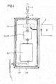
Fig. 1 zeigt eine schematische Ansicht einer möglichen Ausführungsform der erfindungsgemäßen Rauchdetektionsanordnung. -
Fig. 2a zeigt eine schematische Schnittdarstellung eines Ventils in der Ansaugstellung. -
Fig. 2b zeigt das Ventil ausFig. 2a , jedoch in einer Ansicht, in der die versteckten Elemente strichliert eingezeichnet sind. -
Fig. 3a zeigt ein Ventil in einer Schnittdarstellung in der Freiblasstellung. -
Fig. 3b zeigt dasselbe Ventil wieFig. 3a , jedoch in einer Ansicht, in der die versteckten Teile strichliert dargestellt sind. -
Fig. 4 zeigt eine mögliche Ausführungsform eines Kolbens. -
Fig. 5 zeigt eine weitere mögliche Ausführungsform eines Kolbens. -
Fig. 6a und 6b zeigen eine weitere mögliche Ausführungsform. - In der vorliegenden Ausführungsform ist eine Rückführungsleitung 27 vorgesehen, die das angesaugte gasförmige Medium nach der Detektionsvorrichtung zurück in das Rohrleitungssystem oder in das Gebäude leitet.
- Bei der vorliegenden Ausführungsform wird über die Ansaugleitung 3 bzw. das Ansaugsystem 2 ein Teilmassenstrom oder der gesamte Massenstrom der Luft des Rohrleitungssystems 1 entnommen, durch ein Ventil 7 und gegebenenfalls den Filter 25 oder die Trocknungsvorrichtungen 26 in die Detektionsvorrichtung 4 geleitet. In der Detektionsvorrichtung 4 wird festgestellt, ob sich Rauchgasbestandteile in dem abgezweigten Teilmassenstrom befinden. Ist dies der Fall, so wird an eine Steuerzentrale ein Signal weitergeleitet, das dann beispielsweise einen Alarm auslösen kann. Der entnommene Teilmassenstrom wird gegebenenfalls über die Rückführungsleitung 27 zurück in das Rohrleitungssystem 1 geleitet.
- Bevorzugt geschieht die Abzweigung des Teilmassenstroms kontinuierlich. Dadurch können sich in der Ansaugleitung Staub oder ähnliche Partikel ansammeln. Dies kann zur Verlegung der Ansaugleitung bzw. zur Verringerung des Durchflusses führen. Um dies zu vermeiden, ist die Freiblasvorrichtung 5 vorgesehen. Diese umfasst die Überdruckquelle 6, die über eine Leitung mit dem Ventil 7 verbunden ist. Gesteuert wird die Überdruckquelle bzw. der Massenstrom der Überdruckquelle bevorzugt über ein steuerbares Ventil wie beispielsweise ein Magnetventil. Über dieses kann der Überdruck der Überdruckquelle an das Ventil und weiter in die Ansaugleitung 3 geleitet werden, um diese freizublasen.
- Während dieses Freiblasens ist es von großer Wichtigkeit, dass die Verbindung zur Detektionsvorrichtung unterbrochen ist, wie anhand der folgenden Figuren weiter beschrieben wird:
-
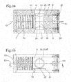
Fig. 2a zeigt eine mögliche Ausführungsform eines Ventils 7 in der Ansaugstellung. Das Ventil 7 umfasst einen Kolben 8, der in einem Ventilgehäuse 9 verschieblich angeordnet ist. Dazu weist das Ventil 7 eine Kolbenöffnung 10 auf, in welcher der Kolben 8 angeordnet ist. Zwischen dem Kolben 8 und dem Ventilgehäuse 9 ist an der Innenseite der Kolbenöffnung der Kolbenspalt 11 vorgesehen. Bevorzugt ist dieser derart schmal ausgeführt, dass ein Gastransport im Wesentlichen verhindert ist. Der Kolben 8 kann entlang der Bewegungsachse 13 verschoben werden. Der Kolben 8 umfasst einen Lüftungskanal 12. Dieser verläuft im Wesentlichen quer zur Bewegungsachse 13 und tritt an einer ersten Stelle 14 der Mantelfläche 15 in den Kolben 8 ein und tritt an einer zweiten Stelle 16 der Mantelfläche wieder aus dem Kolben aus, sodass der Kolben durch den Lüftungskanal 12 durchsetzt ist. Das Ventilgehäuse 9 weist eine erste Lüftungsöffnung 28 sowie eine zweite Lüftungsöffnung 17 auf. In der dargestellten Lüftungsstellung ist der Kolben 8 derart positioniert, dass der Lüftungskanal 12 die erste Lüftungsöffnung 28 mit der zweiten Lüftungsöffnung 17 verbindet und ein Transport des gasförmigen Mediums des Rohrleitungssystems quer durch das Ventil ermöglicht ist. Die erste Lüftungsöffnung 28 ist bevorzugt mit der Ansaugleitung verbunden. - Die zweite Lüftungsöffnung 17 ist in weiterer Folge mit der Detektionsvorrichtung verbunden. In dieser Stellung ist ein Transport der Luft des Rohrleitungssystems zur Detektionsvorrichtung ermöglicht.
- Der Kolben 8 ist durch ein Druckmittel 24 im Wesentlichen in dieser Stellung gehalten. Das Druckmittel 24 ist in der vorliegenden Ausführungsform eine Druckfeder. Pneumatische Federn oder andere elastische Körper können ebenfalls eingesetzt werden. Dabei ist der Kolben 8 über das Druckmittel 24 an den Ventildeckel 30 gedrückt, der dadurch als Anschlag wirkt. Ferner kann der Ventildeckel 30 dazu geeignet und/oder eingerichtet sein, die Überdruckquelle 6 an das Ventil anzuschließen oder auch ein Magnetventil anzuschließen, über das die Zuführung des gasförmigen Mediums der Überdruckquelle 6 ermöglicht ist.
-
Fig. 2b zeigt dasselbe Ventil, jedoch in einer Darstellung, die im Wesentlichen einer 90° verdrehten Ansicht der Ansicht derFig. 2a entspricht. Der Kolben 8 befindet sich in der Ansaugstellung. Die erste Lüftungsöffnung 28 bzw. die zweite Lüftungsöffnung 17 sind im Wesentlichen fluchtend mit dem Lüftungskanal 12 angeordnet. - Im Kolben 8 ist ferner eine Führungsnut 31 vorgesehen, die im Wesentlichen entlang des Mantels 15 und parallel zur Bewegungsachse 13 verläuft. In die Führungsnut 31 ragt ein Führungsmittel 32, das beispielsweise bolzenförmig ausgebildet ist und mit dem Ventilgehäuse 9 verbunden ist. Durch diese Anordnung ist eine Verschiebung des Kolbens 8 entlang der Bewegungsachse 13 ermöglicht, wobei gleichzeitig eine Verdrehung des Kolbens um die Bewegungsachse 13 verhindert ist.
- Ferner sind in dieser Darstellung zwei Entlastungsöffnungen 33 eingezeichnet. Es können beide eingezeichneten Entlastungsöffnungen 33 oder auch nur eine oder keine dieser Entlastungsöffnungen vorgesehen sein. Sie dienen in der vorliegenden Ausführungsform dazu, bei einer Verschiebung des Kolbens, die dadurch verdrängte oder angesaugte Luft abzuführen. Die verdrängte Luft kann entweder nach außen, in den Außenbereich des Ventilgehäuses oder auch in den Lüftungskanal 12 geführt sein. In letzterem Fall wird die Luft dabei über die Führungsnut 31 zu einer Bohrung geführt, die in den Lüftungskanal 12 mündet. Die Entlastungsöffnungen 33 haben bevorzugt einen kleinen Querschnitt, der insbesondere kleiner ist als der Querschnitt des Lüftungskanals 12 und/oder des Freiblaskanals 18.
- Ein weiterer Vorteil des ausschließlichen Vorsehens einer Entlastungsöffnung 33, die in den Lüftungskanal 12 mündet ist, dass das Ansaugen von Fremdluft verhindert ist. Bei der Entlastungsöffnung 33, die sich bis nach außen erstreckt, ist bei der Rückbewegung des Kolbens ein Ansaugen der Umgebungsluft ermöglicht. Dies könnte die Messergebnisse der Detektionsvorrichtung verfälschen. Somit ist gemäß einer bevorzugten Ausführungsform der Druckausgleich durch die Verdrängung des bewegten Kolbens lediglich in den Lüftungskanal 12 ermöglicht. Eine Entlüftungsöffnung 33, die nach außen führt, wäre bei dieser Ausführungsform nicht vorgesehen.
-
Fig. 3a zeigt ein Ventil, insbesondere das Ventil ausFig. 2a , in der Freiblasstellung, bzw. im Übergang zwischen der Ansaugstellung in die Freiblasstellung. Der Kolben 8 ist wiederum im Wesentlichen linear in einem Ventilgehäuse 9 geführt. In der gezeigten Stellung ist der Kolben gegen die Kraft des Druckmittels 24 verschoben. Dieses ist zusammengedrückt und wirkt gegen die zweite Stirnseite 23 des Kolbens 8. Der im Kolben 8 vorgesehene Lüftungskanal 12 ist in dieser Stellung durch das Ventilgehäuse 9 verschlossen. Die erste Lüftungsöffnung 28 sowie die zweite Lüftungsöffnung 17 sind nicht mit dem Lüftungskanal 12 verbunden. Der Kolben 8 umfasst einen Freiblaskanal 18. Dieser erstreckt sich von der ersten Stirnseite 19 des Kolbens 8 bis zu einer dritten Stelle 20 der Mantelfläche 15 des Kolbens 8. Somit ist das gasförmige Medium der Überdruckquelle über den Freiblaskanal 18 in die erste Lüftungsöffnung 28 und weiter in die nicht dargestellte Ansaugleitung 3 geleitet. Zwischen dem Austritt des Lüftungskanals 12 und des Freiblaskanals 18 an der Mantelfläche 15 ist ein Steg 22 vorgesehen. Dieser Steg 22 ist in Achsrichtung 13 breiter ausgeführt, als der Durchmesser der ersten Lüftungsöffnung 28. Dies bewirkt den Effekt, dass wenn der Kolben 8 von der Lüftungsstellung, dargestellt inFig. 2a , in die Freiblasstellung, dargestellt in derFig. 3a wechselt, zwischen den beiden Stellungen eine Sperrstellung durchläuft. In dieser Sperrstellung sind durch den Kolben 8 sowohl die erste Lüftungsöffnung 28 als auch die zweite Lüftungsöffnung 17 verschlossen. Dadurch wird verhindert, dass eine Überschneidung der beiden Kanäle 12 und 18 auftritt, bei der Überdruck der Überdruckquelle über den Lüftungskanal 12 zur Detektionsvorrichtung 4 geleitet wird. - Der Kolben 8 ist durch den Druck des gasförmigen Mediums der Überdruckquelle gegen die Kraft des Druckmittels 24 verschoben. Wird die Überdruckquelle jedoch vom Ventil getrennt, so wird der Kolben 8 über das Druckmittel 24 selbsttätig in die Ansaugstellung zurück bewegt. Dieser besonders einfache und wartungsfreie Aufbau stellt einen wichtigen Kern der Erfindung dar. Um die Bewegung durch die Überdruckquelle zu ermöglichen, kann der Freiblaskanal 18 derart ausgebildet sein, dass der Druck an der ersten Stirnseite 19 größer ist, als im Freiblaskanal 18 und bevorzugt auch größer als in der Ansaugleitung 3 bzw. im Rohrleitungssystem 1. Dies wird beispielsweise dadurch erreicht, dass der Freiblaskanal 18 einen geringeren Durchmesser aufweist, als die Kolbenöffnung 10. Dadurch wirkt ein Teil des Freiblaskanals 18 als Drossel. Der Staudruck bewegt den Kolben gegen die Kraft des Druckmittels 24 in die Sperrstellung und weiter in die Freiblasstellung. Ferner ist die durch die Überdruckquelle auf die erste Stirnseite wirkende Druckkraft größer als die auf die zweite Stirnseite wirkende Kraft des Druckmittels, um eine Verschiebung des Kolbens von der Ansaugstellung in die Freiblasstellung zu bewirken. In der Freiblasstellung mündet der Freiblaskanal 18 in die Ansaugleitung. Diese Verbindung geschieht über die erste Lüftungsöffnung 28. Der Kolben wird in der Freiblasstellung durch ein Kräftegleichgewicht gehalten, solange der Druck der Überdruckquelle auf den Kolben wirkt. Die Gegenkraft kann beispielsweise durch das Druckmittel oder durch einen Anschlag aufgebracht sein.
-
Fig. 3b zeigt eine Ansicht des Ventils ausFig. 3a , die im Wesentlichen 90° verdreht ist. Der Freiblaskanal 18 ist überschneidend mit der ersten Lüftungsöffnung 28 angeordnet. Dadurch kann der Überdruck der Überdruckquelle in die Ansaugleitung 3 geleitet werden. - Wiederum sind zwei alternative Möglichkeiten der Entlastungsöffnungen 33 vorgesehen. Gegebenenfalls können auch beide dargestellten Entlastungsöffnungen 33 vorgesehen sein.
-
Fig. 4 zeigt eine mögliche Ausgestaltung des Kolbens 8 und insbesondere des Freiblaskanals 18.Fig. 4 zeigt jene Ausführungsform, die auch in denFiguren 2 und3 dargestellt ist. Dabei erstreckt sich der Freiblaskanal 18 von der ersten Stirnseite 19 des Kolbens 8 ins Innere des Kolbens und tritt an einer dritten Stelle 20 der Mantelfläche 15 wieder aus dem Kolben 8 aus. Beispielsweise kann dieser Kanal 18 durch einen eingelegten Kern bei der Gussfertigung oder durch zwei Bohrungen erstellt werden. Durch diese Ausgestaltung ist eine Leitung des gasförmigen Mediums von der Überdruckquelle in die Ansaugleitung ermöglicht. -
Fig. 5 zeigt eine alternative Ausführungsform des Kolbens, die sich insbesondere durch die Ausgestaltung des Freiblaskanals 18 unterscheidet. Wiederum verläuft der Freiblaskanal von der ersten Stirnseite 19 des Kolbens 8 zur Mantelfläche 15 bzw. zu einer dritten Stelle 20 der Mantelfläche 15 des Kolbens. Jedoch ist der Freiblaskanal 18 nicht, wie inFig. 4 dargestellt, als innenliegender Kanal ausgeführt, sondern ist durch eine Abschrägung des Kolbens 8 gegeben. - Die
Fig. 6a und 6b zeigen Details einer weiteren Ausführungsform der vorliegenden Erfindung, wobeiFig. 6a eine Schnittdarstellung eines Ventils in der Ansaugstellung zeigt undFig. 6b dasselbe Ventil wieFig. 6a zeigt - jedoch in der Freiblasstellung. - Die grundsätzliche Konfiguration des Ventils entspricht jener der
Fig. 2a oder3a , Zusätzlich zu den beschriebenen Elementen derFig. 2a und3a sind in der Ausführungsform gemäß denFig. 6a und 6b ein Freiblasrohr 34 und eine Ausnehmung 35 vorgesehen. - Das Freiblasrohr 34 ragt vom Gehäuse 9 in die Kolbenöffnung 10, in der der Kolben verschiebbar gelagert ist.
Fig. 6a zeigt das Ventil in der Ansaugstellung. In dieser Stellung ragt das Freiblasrohr 34 in die Ausnehmung 35 des Kolbens 8. Das Freiblasrohr 34 und die Ausnehmung 35 sind dazu im Wesentlichen koaxial ausgerichtet. Insbesondere ist das Freiblasrohr 34 derart ausgestaltet, dass es zumindest teilweise in die Ausnehmung 35 passt. Die Ausnehmung 35 ist bevorzugt an der ersten Stirnseite 19 des Kolbens 8 vorgesehen und erstreckt sich von der ersten Stirnseite 19 des Kolbens 8 in den Kolben 8 hinein. Sowohl die Ausnehmung 35 als auch das Freiblasrohr 34 erstrecken sich bevorzugt entlang der Bewegungsachse 13. - Die Ausnehmung 35 bildet zumindest teilweise den Freiblaskanal 18. In der Ansaugstellung der
Fig. 6a ragt das Freiblasrohr 34 in die Ausnehmung 35. Insbesondere ragt es soweit in die Ausnehmung 35, dass der Freiblaskanal 18 verschlossen ist. Der Freiblaskanal 18 ist dabei durch das Freiblasrohr 34 bzw. durch den Mantel des Freiblasrohrs 34 verschlossen. In der Freiblasstellung derFig. 6b ist der Kolben 8 durch das von der Überdruckquelle zugeführte gasförmige Medium in die Freiblasstellung befördert. In dieser Freiblasstellung mündet der Freiblaskanal 18 in die erste Lüftungsöffnung 28. Das Freiblasrohr 34 befindet sich in der Freiblasstellung gegebenenfalls außerhalb der Ausnehmung 35. Gegebenenfalls ragt das Freiblasrohr 34 jedoch auch in der Freiblasstellung in die Ausnehmung 35. Bevorzugt ist jedoch der Kolben 8 derart verschoben, sodass der Freiblaskanal freigegeben ist, um von der Überdruckquelle kommendes gasförmiges Medium durch den Freiblaskanal 18 zu leiten. - Die Ausnehmung 35 und das Freiblasrohr 34 weisen bevorzugt einen Durchmesser auf, der kleiner ist als der Durchmesser des Kolbens. Durch die verringerte Fläche und die teleskopförmige Anordnung des Freiblasrohrs 34 in der Ausnehmung 35 kann eine verbesserte Bewegungscharakteristik des Kolbens 8 bewirkt werden.
Bevorzugt weisen das Freiblasrohr 34 und die Ausnehmung 35 einen Durchmesser auf, der beispielsweise zwischen einem Fünftel und einem Drittel des Durchmessers des Kolbens liegt. - Darüber hinaus kann in allen Ausführungsformen, wie in den
Fig. 6a und 6b dargestellt, ein Stempel angeordnet sein, der bei zusammengedrückter Feder an dem Gehäuse ansteht um einen definierten Anschlag zu bilden. - In weiterer Folge werden beispielhafte Details der Erfindung weiter beschrieben:
- Das Umschaltventil dient dazu, den Vorgang der Abtrennung des RAS (Rauchansaugsystem) mit anschließender Druckluftbeaufschlagung einerseits elektronikunabhängig zu automatisieren und andererseits eine solche Freiblaseinrichtung deutlich kostengünstiger und kleiner als bisher zu gestalten und, im Falle der automatischen Aktivierung, den Anspruch an die elektronische Steuerung zu verringern, da lediglich ein kleines Magnetventil angesteuert werden muss. Alle nachfolgenden Schalterfordernisse erfolgen rein pneumatisch bzw. mechanisch. Das Umschaltventil besteht z.B. aus einem Gehäuse sowie einem Kolben und einer Rückstellkraft (z.B. einer Feder). Das Gehäuse ist so geformt, dass sich der Kolben im Gehäuse geführt bewegen kann. Der Kolben wird im Gehäuse durch eine geeignete Ausformung am Verdrehen gehindert. Das Gehäuse bietet Vorrichtungen, um sowohl die Rohrleitung als auch die RAS-Zuleitung direkt mit dem Gehäuse luftdicht verbinden zu können.
Das Gehäuse bietet Vorrichtungen, um eine elektronische Ventilsteuereinrichtung mit integriertem Magnetventil luftdicht anbauen zu können. - In der Ruhestellung des Umschaltventils (der Normalbetriebsstellung für den Ansaugbetrieb des RAS) wird der Kolben durch eine Rückstellkraft in seiner Ruhestellung gehalten. In dieser ist eine freie, weitgehend ungehinderte Luftbewegung vom Rohrsystem zum RAS gewährleistet.
Für die Reinigungsfunktion wird am Drucklufteinlass durch eine externe Einrichtung Druckluft zum Einströmen in die Druckkammer gebracht; durch den einseitig am Kolben anstehenden Luftdruck bewegt sich der Kolben gegen die Rückstellkraft, verschließt zuerst den Durchfluss zwischen dem Rohrsystem und dem RAS und gibt danach den Durchfluss der Druckluft in das Rohrsystem frei; er befindet sich dann in seiner Arbeitsstellung bzw. der Freiblasstellung. - Um die Bewegung des Kolbens nicht durch den Aufbau eines Gegendruckes durch die Volumenverkleinerung in der Federkammer zu behindern sowie um dem Kolben nach Abschalten der Druckluftzufuhr die ungehinderte Rückkehr in die Ruhestellung zu ermöglichen ist eine Entlastungsöffnung vorgesehen; diese Öffnung kann entweder von der Federkammer durch die Gehäusewand in die Umgebung führen oder durch eine Verbindungsöffnung in den RAS-Ansaugkanal des Kolbens führen. Durch die Anordnung dieser Öffnung in den RAS-Ansaugkanal wird verhindert, dass im Ansaugbetrieb geringe Mengen an Fremdluft durch die Entlastungsöffnung angesaugt wird und dadurch das zu messende Medium verdünnt wird. Eine weitere Funktion der Entlastungsbohrung ist, dass sie bei entsprechender Dimensionierung die Aufprallgeschwindigkeit des Kolbens am Gehäuse durch den sich temporär aufbauenden Gaspolster begrenzt.
- Die Druckluftführung von der Druckkammer in das Rohrsystem kann entweder innerhalb des Kolbens durch einen geeigneten Luftführungsdurchgang erfolgen oder direkt aus der Druckkammer in das Rohrsystem indem der Kolben diesen Weg in der Arbeitsstellung freigibt.
- Der Kolben wird mittels dem sich einstellenden Gegendruck an die Öffnungsbohrung, die in das RAS führt, gepresst. Durch die Wahl eines elastischen Materials ist an dieser Stelle eine vollständige Abdichtung der Öffnung zum RAS gewährleistet.
-
- 1. Rohrleitungssystem
- 2. Ansaugsystem
- 3. Ansaugleitung
- 4. Detektionsvorrichtung
- 5. Freiblasvorrichtung
- 6. Überdruckquelle
- 7. Ventil
- 8. Kolben
- 9. Ventilgehäuse
- 10. Kolbenöffnung
- 11. Kolbenspalt
- 12. Lüftungskanal
- 13. Bewegungsachse
- 14. erste Stelle der Mantelfläche
- 15. Mantelfläche
- 16. zweite Stelle der Mantelfläche
- 17. zweite Lüftungsöffnung
- 18. Freiblaskanal
- 19. erste Stirnseite des Kolbens
- 20. dritte Stelle der Mantelfläche
- 21. Freiblasöffnung
- 22. Steg
- 23. zweite Stirnseite des Kolbens
- 24. Druckmittel
- 25. Filter
- 26. Trocknungsvorrichtung
- 27. Rückführungsleitung
- 28. erste Lüftungsöffnung
- 29. Gehäuse
- 30. Ventildeckel
- 31. Führungsnut
- 32. Führungsmittel
- 33. Entlastungsöffnung
- 34. Freiblasrohr
- 35. Ausnehmung
Claims (15)
- Rauchdetektionsanordnung zur Detektion von Rauchgas und/oder Rauchpartikeln in der Luft eines Gebäudes, umfassend:- ein Ansaugsystem (2) zur Ansaugung von Luft über ein Rohrleitungssystem(1),- eine Ansaugleitung (3), über die das Rohrleitungssystem (1) mit dem Ansaugsystem (2) verbunden ist,- eine Detektionsvorrichtung (4), die mit dem Ansaugsystem (2) und/oder der Ansaugleitung (3) verbunden ist, um Rauchgas in der aus dem Rohrleitungssystem (1) angesaugten Luft zu detektieren,- eine Freiblasvorrichtung (5) mit einer Überdruckquelle (6) zur Einleitung eines gasförmigen Mediums in die Ansaugleitung (3), wobei ein Ventil (7) vorgesehen ist, über das eine Verbindung der Überdruckquelle (6) mit der Ansaugleitung (3) geöffnet oder geschlossen werden kann,dadurch gekennzeichnet,
dass das Ventil (7) eine Ansaugstellung aufweist, in der die Detektionsvorrichtung (4) mit dem Ansaugsystem (2) und der Ansaugleitung (3) verbunden ist,
dass das Ventil (7) eine Freiblasstellung aufweist, in der die Detektionsvorrichtung (4) von der Ansaugleitung (3) getrennt ist und in der die Überdruckquelle (6) mit der Ansaugleitung (3) verbunden ist,
und dass, wenn ein Überdruck von der Überdruckquelle (6) auf das Ventil wirkt, das Ventil (7), angetrieben vom gasförmigen Medium der Überdruckquelle (6), selbsttätig von der Ansaugstellung in die Freiblasstellung wechselt. - Rauchdetektionsanordnung nach Anspruch 1, dadurch gekennzeichnet, dass das Ventil (7) zwischen der Freiblasstellung und der Ansaugstellung eine Sperrstellung aufweist, in der die Überdruckquelle (6), die Detektionsvorrichtung (4) und die Ansaugleitung voneinander getrennt sind.
- Rauchdetektionsanordnung nach Anspruch 1 oder 2, dadurch gekennzeichnet,
dass das Ventil (7) einen Kolben (8) aufweist, der in einem Ventilgehäuse (9) von der Ansaugstellung in die Freiblasstellung bewegbar ist. - Rauchdetektionsanordnung nach Anspruch 3, dadurch gekennzeichnet, dass das Ventilgehäuse (9) eine Kolbenöffnung (10) aufweist, deren Profil im Wesentlichen dem Profil des Kolbens (8) entspricht, sodass dieser in der Kolbenöffnung (10) geführt ist und dass bevorzugt der Kolbenspalt (11) zwischen Kolbenöffnung (10) und Kolben (8) im Wesentlichen abgedichtet ist, wobei der Kolben im Ventilgehäuse (9) gegebenenfalls linear geführt ist.
- Rauchdetektionsanordnung nach Anspruch 3 oder 4, dadurch gekennzeichnet,
dass der Kolben (8) einen Lüftungskanal (12) umfasst, der im Wesentlichen quer zur Bewegungsachse (13) verläuft und an einer ersten Stelle (14) der Mantelfläche (15) in den Kolben (8) eintritt und an einer zweiten Stelle (16) der Mantelfläche (15) austritt, sodass der Kolben (8) durch den Lüftungskanal (12) durchsetzt ist, dass das Ventilgehäuse (9) eine erste Lüftungsöffnung (28) und eine zweite Lüftungsöffnung (17) umfasst, und dass in der Ansaugstellung des Ventils (7) die erste Lüftungsöffnung (28) über den Lüftungskanal (12) des Kolbens (8) mit der zweiten Lüftungsöffnung (17) verbunden ist. - Rauchdetektionsanordnung nach einem der Ansprüche 3 bis 5, dadurch gekennzeichnet, dass der Kolben (8) einen Freiblaskanal (18) umfasst der sich von der ersten Stirnseite (19) des Kolbens (8) bis zu einer dritten Stelle (20) der Mantelfläche (15) des Kolbens (8) erstreckt,
dass das Ventilgehäuse (9) eine Freiblasöffnung (21) umfasst,
und dass in der Freiblasstellung des Ventils (7) die Freiblasöffnung (21) über den Freiblaskanal (18) des Kolbens (8) mit der ersten Lüftungsöffnung (16) verbunden ist. - Rauchdetektionsanordnung nach einem der Ansprüche 3 bis 6, dadurch gekennzeichnet, dass zwischen dem Lüftungskanal (12) an der ersten Stelle (14) der Mantelfläche (15) des Kolbens (8) und dem Freiblaskanal (18) an der dritten Stelle (20) der Mantelfläche (15) des Kolbens (8) ein Steg (22) vorgesehen ist, durch welchen die erste Lüftungsöffnung (28) in der Sperrstellung, insbesondere beim Übergang von der Ansaugstellung in die Freiblasstellung, verschlossen ist.
- Rauchdetektionsanordnung nach einem der Ansprüche 3 bis 7, dadurch gekennzeichnet, dass an der zweiten Stirnseite (23) des Kolbens (8) ein Druckmittel (24), bevorzugt ein elastischer Körper wie beispielsweise eine Druckfeder, vorgesehen ist, die insbesondere in der Freiblasstellung gegen den die zweite Stirnseite (23) des Kolbens (8) wirkt, und dass die Druckkraft des Druckmittels (24) in der Ansaugstellung geringer ist, als die durch die Überdruckquelle (6) auf die erste Stirnseite (19) wirkende Druckkraft, sodass sich der Kolben (8) bei angelegter Druckkraft der Überdruckquelle in die Freiblasstellung bewegt und/oder in der Freiblasstellung befindet.
- Rauchdetektionsanordnung nach einem der Ansprüche 6 bis 8, dadurch gekennzeichnet, dass der auf die erste Stirnseite (19) des Kolbens (8) wirkende Druck des gasförmigen Mediums der Überdruckquelle größer ist, als der Druck des gasförmigen Mediums in der Freiblasleitung.
- Rauchdetektionsanordnung nach einem der Ansprüche 1 bis 9, dadurch gekennzeichnet, dass der Druck des gasförmigen Mediums zum Freiblasen der Ansaugleitung im Ventil (7) oder beim Austritt aus dem Ventil (7) größer ist, als der herrschen Luftdruck in der Ansaugleitung (3), sodass das gasförmige Medium der Überdruckquelle zum Freiblasen der Ansaugleitung gegen die Ansaugrichtung in die Ansaugleitung und gegebenenfalls in das Rohrleitungssystem geleitet wird.
- Rauchdetektionsanordnung nach einem der Ansprüche 6 bis 10, dadurch gekennzeichnet, dass das Ventil (7) und/oder der Kolben (8) von der Freiblasstellung selbsttätig in die Ansaugstellung zurückkehrt, wenn die auf die erste Stirnseite (19) des Kolbens (8) wirkende Druckkraft kleiner ist, als die Kraft des Druckmittels.
- Rauchdetektionsanordnung nach einem der Ansprüche 1 bis 11, dadurch gekennzeichnet, dass das Ansaugsystem (2) kontinuierlich Luft und gegebenenfalls in der Luft enthaltenes Rauchgas in die Detektionsvorrichtung (4) fördert, um eine kontinuierliche Rauchgasdetektion zu ermöglichen, dass im Ansaugbereich der Detektionsvorrichtung (4) ein Filter (25), eine Trocknungsvorrichtung (26), eine Kühlvorrichtung oder ähnliche Komponenten vorgesehen sind und/oder dass die in die Detektionsvorrichtung (4) geleitete Luft über eine Rückführungsleitung (27) wieder zurück in das Rohrleitungssystem (1) und/oder das Gebäude geleitet ist.
- Rauchdetektionsanordnung nach einem der Ansprüche 1 bis 12, dadurch gekennzeichnet, dass die Komponenten Ventil (7), Detektionsvorrichtung (4), Ansaugsystem (2) als Einheit in einem Gehäuse angeordnet sind.
- Rauchdetektionsanordnung nach einem der Ansprüche 1 bis 13, dadurch gekennzeichnet, dass der Kolben (8) als runder, insbesondere zylindrischer Kolben ausgeführt ist, der entlang seiner Drehachse bewegbar geführt, jedoch gegen eine Verdrehung gesichert ist.
- Rauchdetektionsanordnung nach einem der Ansprüche 1 bis 14, dadurch gekennzeichnet, dass an der ersten Stirnseite des Kolbens (8) eine entlang der Bewegungsachse (13) in den Kolben (8) verlaufende Ausnehmung (35) oder Bohrung vorgesehen ist, die zumindest einen Teil des Freiblaskanals (18) bildet, dass ein Freiblasrohr (34) vorgesehen ist, das sich vom Gehäuse entlang der Bewegungsachse (13) in die Kolbenöffnung (10) erstreckt und an dessen freien Ende die Freiblasöffnung (21) vorgesehen ist, sodass von der Überdruckquelle (6) kommendes gasförmigen Mediums durch das Freiblasrohr (34) und die Freiblasöffnung (21) Richtung Kolben geleitet werden kann, und dass das Freiblasrohr (34) in der Ansaugstellung in die Ausnehmung (35) ragt.
Applications Claiming Priority (1)
| Application Number | Priority Date | Filing Date | Title |
|---|---|---|---|
| ATA854/2013A AT514912B1 (de) | 2013-11-07 | 2013-11-07 | Rauchdetektionsanordnung |
Publications (2)
| Publication Number | Publication Date |
|---|---|
| EP2871620A1 EP2871620A1 (de) | 2015-05-13 |
| EP2871620B1 true EP2871620B1 (de) | 2018-01-03 |
Family
ID=51897117
Family Applications (1)
| Application Number | Title | Priority Date | Filing Date |
|---|---|---|---|
| EP14191904.3A Active EP2871620B1 (de) | 2013-11-07 | 2014-11-05 | Rauchdetektionsanordnung |
Country Status (2)
| Country | Link |
|---|---|
| EP (1) | EP2871620B1 (de) |
| AT (1) | AT514912B1 (de) |
Families Citing this family (5)
| Publication number | Priority date | Publication date | Assignee | Title |
|---|---|---|---|---|
| EP3327689B1 (de) * | 2016-11-25 | 2020-10-14 | Wagner Group GmbH | Filterbauteil |
| US10169982B1 (en) * | 2017-07-03 | 2019-01-01 | Honeywell International Inc. | Systems and methods for delaying or activating a blowout device or a purge device in a sampling pipe network of an aspirated smoke detection system |
| CN108489871A (zh) * | 2018-06-22 | 2018-09-04 | 佛山瀚兽环境科技服务有限公司 | 用于废气排放在线监控装置的监测装置 |
| CN109611330B (zh) * | 2019-01-23 | 2024-04-05 | 深圳市球形动力科技有限公司 | 一种双向旋转球形泵冷却机构 |
| CN110487879B (zh) * | 2019-09-05 | 2022-06-21 | 宁夏诺克银丰智能科技有限公司 | 一种气体报警检测装置 |
Family Cites Families (5)
| Publication number | Priority date | Publication date | Assignee | Title |
|---|---|---|---|---|
| GB2243475B (en) * | 1990-04-26 | 1993-12-01 | David Theodore Nels Williamson | Improvements to gas and smoke alarm systems |
| DE10257951A1 (de) * | 2002-12-12 | 2004-07-01 | Leybold Vakuum Gmbh | Kolbenkompressor |
| US7034702B2 (en) * | 2003-12-23 | 2006-04-25 | Robert Bosch Gmbh | Optical smoke detector and method of cleaning |
| AT10188U1 (de) * | 2007-06-15 | 2008-10-15 | Hacker & Petermann Gmbh | Freiblassystem und verfahren zum automatischen reinigen von fühlrohren von rauchansaugsystemen |
| MY167512A (en) * | 2009-07-07 | 2018-09-04 | Xtralis Technologies Ltd | Chamber condition |
-
2013
- 2013-11-07 AT ATA854/2013A patent/AT514912B1/de not_active IP Right Cessation
-
2014
- 2014-11-05 EP EP14191904.3A patent/EP2871620B1/de active Active
Also Published As
| Publication number | Publication date |
|---|---|
| AT514912B1 (de) | 2015-05-15 |
| EP2871620A1 (de) | 2015-05-13 |
| AT514912A4 (de) | 2015-05-15 |
Similar Documents
| Publication | Publication Date | Title |
|---|---|---|
| EP2871620B1 (de) | Rauchdetektionsanordnung | |
| EP2037792B1 (de) | Nebenluftventil | |
| EP0242684A2 (de) | Lecksuchgerät mit Detektor und Testleck | |
| DE3730837A1 (de) | Entlueftungseinrichtung fuer giessanlagen | |
| DE102014009231A1 (de) | Absperr-Filtervorrichtung | |
| DE19812275B4 (de) | Transportvorrichtung | |
| DE102011121493A1 (de) | Luftaufbereitungsvorrichtung für ein Druckluftsystem eines Fahrzeuges | |
| EP3327689B1 (de) | Filterbauteil | |
| EP2728226B1 (de) | Vakuumventil | |
| DE4101248C2 (de) | Strömungsventil | |
| EP1081441A2 (de) | Luft-Volumenstromregler für Sicherheitseinrichtungen, insbesondere Laborabzüge | |
| EP0360370B1 (de) | Tauchtiefengesteuerte Ausblasventil-Einrichtung | |
| DE10358531A1 (de) | Vorrichtung und Verfahren zum Detektieren von Entstehungsbränden | |
| DE10329428B4 (de) | Vorrichtung zum Absperren und/oder Steuern und/oder Regeln eines Luftstroms | |
| DE2950658A1 (de) | Vorrichtung zur entnahme und analyse einer gasprobe eines waermetauschers | |
| DE19620252C2 (de) | Austauschbares Filterelement für Sicherheitswerkbänke in Krankenhäusern, Apotheken, Forschungslabors o. dgl. | |
| DE930710C (de) | Vorrichtung zum Sichtbarmachen von stroemender Luft | |
| EP4151569A1 (de) | Absperrschieber mit bypassvorrichtung | |
| DE102006035895A1 (de) | Vorrichtung zum Auffangen von gasförmigen Emissionen bei der Materialbearbeitung sowie ein an der Vorrichtung fixierbares Dichtungselement | |
| DE102016221674B4 (de) | Steuerung für eine Vorrichtung zur Herstellung von Druckgussteilen | |
| DE102015015089A1 (de) | Überdruckkapselungssystem zum Explosionsschutz und entsprechendes Betriebsverfahren | |
| EP0096909B1 (de) | Umschaltvorrichtung für einen Konverter-Gasstrom | |
| DE935493C (de) | Vakuumventil mit einer zylindrischen Kammer | |
| DE10309988B4 (de) | Vorrichtung zur Prozessluftkonditionierung und/oder -entsorgung | |
| DE102019122282A1 (de) | Aufbewahrungsfach für Druckmaterial eines Additiv-Manufacturing-Systems, insbesondere eines 3D-Druckers |
Legal Events
| Date | Code | Title | Description |
|---|---|---|---|
| PUAI | Public reference made under article 153(3) epc to a published international application that has entered the european phase |
Free format text: ORIGINAL CODE: 0009012 |
|
| 17P | Request for examination filed |
Effective date: 20141105 |
|
| AK | Designated contracting states |
Kind code of ref document: A1 Designated state(s): AL AT BE BG CH CY CZ DE DK EE ES FI FR GB GR HR HU IE IS IT LI LT LU LV MC MK MT NL NO PL PT RO RS SE SI SK SM TR |
|
| AX | Request for extension of the european patent |
Extension state: BA ME |
|
| R17P | Request for examination filed (corrected) |
Effective date: 20151113 |
|
| RBV | Designated contracting states (corrected) |
Designated state(s): AL AT BE BG CH CY CZ DE DK EE ES FI FR GB GR HR HU IE IS IT LI LT LU LV MC MK MT NL NO PL PT RO RS SE SI SK SM TR |
|
| GRAP | Despatch of communication of intention to grant a patent |
Free format text: ORIGINAL CODE: EPIDOSNIGR1 |
|
| RIC1 | Information provided on ipc code assigned before grant |
Ipc: G08B 29/00 20060101ALI20170706BHEP Ipc: G01N 1/26 20060101ALI20170706BHEP Ipc: G01N 15/00 20060101ALI20170706BHEP Ipc: G08B 17/107 20060101ALI20170706BHEP Ipc: G01N 33/00 20060101ALI20170706BHEP Ipc: B08B 9/00 20060101ALI20170706BHEP Ipc: B08B 5/02 20060101ALI20170706BHEP Ipc: G08B 17/10 20060101AFI20170706BHEP Ipc: G08B 17/113 20060101ALI20170706BHEP |
|
| INTG | Intention to grant announced |
Effective date: 20170801 |
|
| GRAS | Grant fee paid |
Free format text: ORIGINAL CODE: EPIDOSNIGR3 |
|
| GRAA | (expected) grant |
Free format text: ORIGINAL CODE: 0009210 |
|
| AK | Designated contracting states |
Kind code of ref document: B1 Designated state(s): AL AT BE BG CH CY CZ DE DK EE ES FI FR GB GR HR HU IE IS IT LI LT LU LV MC MK MT NL NO PL PT RO RS SE SI SK SM TR |
|
| REG | Reference to a national code |
Ref country code: GB Ref legal event code: FG4D Free format text: NOT ENGLISH |
|
| REG | Reference to a national code |
Ref country code: CH Ref legal event code: EP Ref country code: AT Ref legal event code: REF Ref document number: 960942 Country of ref document: AT Kind code of ref document: T Effective date: 20180115 |
|
| REG | Reference to a national code |
Ref country code: IE Ref legal event code: FG4D Free format text: LANGUAGE OF EP DOCUMENT: GERMAN |
|
| REG | Reference to a national code |
Ref country code: DE Ref legal event code: R096 Ref document number: 502014006795 Country of ref document: DE |
|
| REG | Reference to a national code |
Ref country code: CH Ref legal event code: NV Representative=s name: BOHEST AG, CH |
|
| REG | Reference to a national code |
Ref country code: NL Ref legal event code: FP |
|
| REG | Reference to a national code |
Ref country code: LT Ref legal event code: MG4D |
|
| PG25 | Lapsed in a contracting state [announced via postgrant information from national office to epo] |
Ref country code: ES Free format text: LAPSE BECAUSE OF FAILURE TO SUBMIT A TRANSLATION OF THE DESCRIPTION OR TO PAY THE FEE WITHIN THE PRESCRIBED TIME-LIMIT Effective date: 20180103 Ref country code: CY Free format text: LAPSE BECAUSE OF FAILURE TO SUBMIT A TRANSLATION OF THE DESCRIPTION OR TO PAY THE FEE WITHIN THE PRESCRIBED TIME-LIMIT Effective date: 20180103 Ref country code: FI Free format text: LAPSE BECAUSE OF FAILURE TO SUBMIT A TRANSLATION OF THE DESCRIPTION OR TO PAY THE FEE WITHIN THE PRESCRIBED TIME-LIMIT Effective date: 20180103 Ref country code: NO Free format text: LAPSE BECAUSE OF FAILURE TO SUBMIT A TRANSLATION OF THE DESCRIPTION OR TO PAY THE FEE WITHIN THE PRESCRIBED TIME-LIMIT Effective date: 20180403 Ref country code: LT Free format text: LAPSE BECAUSE OF FAILURE TO SUBMIT A TRANSLATION OF THE DESCRIPTION OR TO PAY THE FEE WITHIN THE PRESCRIBED TIME-LIMIT Effective date: 20180103 Ref country code: HR Free format text: LAPSE BECAUSE OF FAILURE TO SUBMIT A TRANSLATION OF THE DESCRIPTION OR TO PAY THE FEE WITHIN THE PRESCRIBED TIME-LIMIT Effective date: 20180103 |
|
| PG25 | Lapsed in a contracting state [announced via postgrant information from national office to epo] |
Ref country code: BG Free format text: LAPSE BECAUSE OF FAILURE TO SUBMIT A TRANSLATION OF THE DESCRIPTION OR TO PAY THE FEE WITHIN THE PRESCRIBED TIME-LIMIT Effective date: 20180403 Ref country code: RS Free format text: LAPSE BECAUSE OF FAILURE TO SUBMIT A TRANSLATION OF THE DESCRIPTION OR TO PAY THE FEE WITHIN THE PRESCRIBED TIME-LIMIT Effective date: 20180103 Ref country code: LV Free format text: LAPSE BECAUSE OF FAILURE TO SUBMIT A TRANSLATION OF THE DESCRIPTION OR TO PAY THE FEE WITHIN THE PRESCRIBED TIME-LIMIT Effective date: 20180103 Ref country code: SE Free format text: LAPSE BECAUSE OF FAILURE TO SUBMIT A TRANSLATION OF THE DESCRIPTION OR TO PAY THE FEE WITHIN THE PRESCRIBED TIME-LIMIT Effective date: 20180103 Ref country code: IS Free format text: LAPSE BECAUSE OF FAILURE TO SUBMIT A TRANSLATION OF THE DESCRIPTION OR TO PAY THE FEE WITHIN THE PRESCRIBED TIME-LIMIT Effective date: 20180503 Ref country code: GR Free format text: LAPSE BECAUSE OF FAILURE TO SUBMIT A TRANSLATION OF THE DESCRIPTION OR TO PAY THE FEE WITHIN THE PRESCRIBED TIME-LIMIT Effective date: 20180404 Ref country code: PL Free format text: LAPSE BECAUSE OF FAILURE TO SUBMIT A TRANSLATION OF THE DESCRIPTION OR TO PAY THE FEE WITHIN THE PRESCRIBED TIME-LIMIT Effective date: 20180103 |
|
| PG25 | Lapsed in a contracting state [announced via postgrant information from national office to epo] |
Ref country code: MT Free format text: LAPSE BECAUSE OF FAILURE TO SUBMIT A TRANSLATION OF THE DESCRIPTION OR TO PAY THE FEE WITHIN THE PRESCRIBED TIME-LIMIT Effective date: 20180103 |
|
| REG | Reference to a national code |
Ref country code: DE Ref legal event code: R097 Ref document number: 502014006795 Country of ref document: DE |
|
| PG25 | Lapsed in a contracting state [announced via postgrant information from national office to epo] |
Ref country code: IT Free format text: LAPSE BECAUSE OF FAILURE TO SUBMIT A TRANSLATION OF THE DESCRIPTION OR TO PAY THE FEE WITHIN THE PRESCRIBED TIME-LIMIT Effective date: 20180103 Ref country code: RO Free format text: LAPSE BECAUSE OF FAILURE TO SUBMIT A TRANSLATION OF THE DESCRIPTION OR TO PAY THE FEE WITHIN THE PRESCRIBED TIME-LIMIT Effective date: 20180103 Ref country code: EE Free format text: LAPSE BECAUSE OF FAILURE TO SUBMIT A TRANSLATION OF THE DESCRIPTION OR TO PAY THE FEE WITHIN THE PRESCRIBED TIME-LIMIT Effective date: 20180103 Ref country code: AL Free format text: LAPSE BECAUSE OF FAILURE TO SUBMIT A TRANSLATION OF THE DESCRIPTION OR TO PAY THE FEE WITHIN THE PRESCRIBED TIME-LIMIT Effective date: 20180103 |
|
| PLBE | No opposition filed within time limit |
Free format text: ORIGINAL CODE: 0009261 |
|
| STAA | Information on the status of an ep patent application or granted ep patent |
Free format text: STATUS: NO OPPOSITION FILED WITHIN TIME LIMIT |
|
| PG25 | Lapsed in a contracting state [announced via postgrant information from national office to epo] |
Ref country code: DK Free format text: LAPSE BECAUSE OF FAILURE TO SUBMIT A TRANSLATION OF THE DESCRIPTION OR TO PAY THE FEE WITHIN THE PRESCRIBED TIME-LIMIT Effective date: 20180103 Ref country code: SM Free format text: LAPSE BECAUSE OF FAILURE TO SUBMIT A TRANSLATION OF THE DESCRIPTION OR TO PAY THE FEE WITHIN THE PRESCRIBED TIME-LIMIT Effective date: 20180103 Ref country code: CZ Free format text: LAPSE BECAUSE OF FAILURE TO SUBMIT A TRANSLATION OF THE DESCRIPTION OR TO PAY THE FEE WITHIN THE PRESCRIBED TIME-LIMIT Effective date: 20180103 Ref country code: SK Free format text: LAPSE BECAUSE OF FAILURE TO SUBMIT A TRANSLATION OF THE DESCRIPTION OR TO PAY THE FEE WITHIN THE PRESCRIBED TIME-LIMIT Effective date: 20180103 |
|
| 26N | No opposition filed |
Effective date: 20181005 |
|
| PG25 | Lapsed in a contracting state [announced via postgrant information from national office to epo] |
Ref country code: SI Free format text: LAPSE BECAUSE OF FAILURE TO SUBMIT A TRANSLATION OF THE DESCRIPTION OR TO PAY THE FEE WITHIN THE PRESCRIBED TIME-LIMIT Effective date: 20180103 |
|
| PG25 | Lapsed in a contracting state [announced via postgrant information from national office to epo] |
Ref country code: MC Free format text: LAPSE BECAUSE OF FAILURE TO SUBMIT A TRANSLATION OF THE DESCRIPTION OR TO PAY THE FEE WITHIN THE PRESCRIBED TIME-LIMIT Effective date: 20180103 Ref country code: LU Free format text: LAPSE BECAUSE OF NON-PAYMENT OF DUE FEES Effective date: 20181105 |
|
| REG | Reference to a national code |
Ref country code: BE Ref legal event code: MM Effective date: 20181130 |
|
| REG | Reference to a national code |
Ref country code: IE Ref legal event code: MM4A |
|
| PG25 | Lapsed in a contracting state [announced via postgrant information from national office to epo] |
Ref country code: IE Free format text: LAPSE BECAUSE OF NON-PAYMENT OF DUE FEES Effective date: 20181105 |
|
| PG25 | Lapsed in a contracting state [announced via postgrant information from national office to epo] |
Ref country code: BE Free format text: LAPSE BECAUSE OF NON-PAYMENT OF DUE FEES Effective date: 20181130 |
|
| PG25 | Lapsed in a contracting state [announced via postgrant information from national office to epo] |
Ref country code: TR Free format text: LAPSE BECAUSE OF FAILURE TO SUBMIT A TRANSLATION OF THE DESCRIPTION OR TO PAY THE FEE WITHIN THE PRESCRIBED TIME-LIMIT Effective date: 20180103 |
|
| PG25 | Lapsed in a contracting state [announced via postgrant information from national office to epo] |
Ref country code: PT Free format text: LAPSE BECAUSE OF FAILURE TO SUBMIT A TRANSLATION OF THE DESCRIPTION OR TO PAY THE FEE WITHIN THE PRESCRIBED TIME-LIMIT Effective date: 20180103 |
|
| PG25 | Lapsed in a contracting state [announced via postgrant information from national office to epo] |
Ref country code: MK Free format text: LAPSE BECAUSE OF NON-PAYMENT OF DUE FEES Effective date: 20180103 Ref country code: HU Free format text: LAPSE BECAUSE OF FAILURE TO SUBMIT A TRANSLATION OF THE DESCRIPTION OR TO PAY THE FEE WITHIN THE PRESCRIBED TIME-LIMIT; INVALID AB INITIO Effective date: 20141105 |
|
| P01 | Opt-out of the competence of the unified patent court (upc) registered |
Effective date: 20230516 |
|
| PGFP | Annual fee paid to national office [announced via postgrant information from national office to epo] |
Ref country code: NL Payment date: 20231120 Year of fee payment: 10 |
|
| PGFP | Annual fee paid to national office [announced via postgrant information from national office to epo] |
Ref country code: GB Payment date: 20231123 Year of fee payment: 10 |
|
| PGFP | Annual fee paid to national office [announced via postgrant information from national office to epo] |
Ref country code: FR Payment date: 20231120 Year of fee payment: 10 Ref country code: DE Payment date: 20231103 Year of fee payment: 10 Ref country code: CH Payment date: 20231202 Year of fee payment: 10 Ref country code: AT Payment date: 20231024 Year of fee payment: 10 |