EP2870613B2 - Elektromagnet, elektromagnetisch betätigbare bremse und bremsmotor - Google Patents
Elektromagnet, elektromagnetisch betätigbare bremse und bremsmotor Download PDFInfo
- Publication number
- EP2870613B2 EP2870613B2 EP13726114.5A EP13726114A EP2870613B2 EP 2870613 B2 EP2870613 B2 EP 2870613B2 EP 13726114 A EP13726114 A EP 13726114A EP 2870613 B2 EP2870613 B2 EP 2870613B2
- Authority
- EP
- European Patent Office
- Prior art keywords
- brake
- magnet body
- coil
- pole
- electromagnet
- Prior art date
- Legal status (The legal status is an assumption and is not a legal conclusion. Google has not performed a legal analysis and makes no representation as to the accuracy of the status listed.)
- Active
Links
Images


Classifications
-
- F—MECHANICAL ENGINEERING; LIGHTING; HEATING; WEAPONS; BLASTING
- F16—ENGINEERING ELEMENTS AND UNITS; GENERAL MEASURES FOR PRODUCING AND MAINTAINING EFFECTIVE FUNCTIONING OF MACHINES OR INSTALLATIONS; THERMAL INSULATION IN GENERAL
- F16D—COUPLINGS FOR TRANSMITTING ROTATION; CLUTCHES; BRAKES
- F16D63/00—Brakes not otherwise provided for; Brakes combining more than one of the types of groups F16D49/00 - F16D61/00
- F16D63/002—Brakes with direct electrical or electro-magnetic actuation
-
- F—MECHANICAL ENGINEERING; LIGHTING; HEATING; WEAPONS; BLASTING
- F16—ENGINEERING ELEMENTS AND UNITS; GENERAL MEASURES FOR PRODUCING AND MAINTAINING EFFECTIVE FUNCTIONING OF MACHINES OR INSTALLATIONS; THERMAL INSULATION IN GENERAL
- F16D—COUPLINGS FOR TRANSMITTING ROTATION; CLUTCHES; BRAKES
- F16D59/00—Self-acting brakes, e.g. coming into operation at a predetermined speed
- F16D59/02—Self-acting brakes, e.g. coming into operation at a predetermined speed spring-loaded and adapted to be released by mechanical, fluid, or electromagnetic means
-
- H—ELECTRICITY
- H01—ELECTRIC ELEMENTS
- H01F—MAGNETS; INDUCTANCES; TRANSFORMERS; SELECTION OF MATERIALS FOR THEIR MAGNETIC PROPERTIES
- H01F7/00—Magnets
- H01F7/06—Electromagnets; Actuators including electromagnets
- H01F7/08—Electromagnets; Actuators including electromagnets with armatures
- H01F7/081—Magnetic constructions
-
- H—ELECTRICITY
- H01—ELECTRIC ELEMENTS
- H01F—MAGNETS; INDUCTANCES; TRANSFORMERS; SELECTION OF MATERIALS FOR THEIR MAGNETIC PROPERTIES
- H01F7/00—Magnets
- H01F7/06—Electromagnets; Actuators including electromagnets
- H01F7/08—Electromagnets; Actuators including electromagnets with armatures
- H01F7/16—Rectilinearly-movable armatures
- H01F7/1638—Armatures not entering the winding
-
- H—ELECTRICITY
- H01—ELECTRIC ELEMENTS
- H01F—MAGNETS; INDUCTANCES; TRANSFORMERS; SELECTION OF MATERIALS FOR THEIR MAGNETIC PROPERTIES
- H01F7/00—Magnets
- H01F7/06—Electromagnets; Actuators including electromagnets
- H01F7/20—Electromagnets; Actuators including electromagnets without armatures
-
- F—MECHANICAL ENGINEERING; LIGHTING; HEATING; WEAPONS; BLASTING
- F16—ENGINEERING ELEMENTS AND UNITS; GENERAL MEASURES FOR PRODUCING AND MAINTAINING EFFECTIVE FUNCTIONING OF MACHINES OR INSTALLATIONS; THERMAL INSULATION IN GENERAL
- F16D—COUPLINGS FOR TRANSMITTING ROTATION; CLUTCHES; BRAKES
- F16D2121/00—Type of actuator operation force
- F16D2121/18—Electric or magnetic
- F16D2121/20—Electric or magnetic using electromagnets
- F16D2121/22—Electric or magnetic using electromagnets for releasing a normally applied brake
-
- H—ELECTRICITY
- H01—ELECTRIC ELEMENTS
- H01F—MAGNETS; INDUCTANCES; TRANSFORMERS; SELECTION OF MATERIALS FOR THEIR MAGNETIC PROPERTIES
- H01F3/00—Cores, Yokes, or armatures
- H01F3/10—Composite arrangements of magnetic circuits
- H01F2003/106—Magnetic circuits using combinations of different magnetic materials
Definitions
- the invention relates to an electromagnet, an electromagnetically actuable brake and a brake motor.
- an electromagnet has a coil winding that is laid in a magnet body.
- the invention is therefore based on the object of further developing simple production and a brake that is as compact as possible and efficient.
- the object is achieved with the electromagnet according to the features specified in claim 1, with the electromagnetically actuable brake according to the features specified in claim 10 and with the brake motor according to the features specified in claim 11.
- the advantage here is that the inner pole conducts a high magnetic field strength without going into saturation.
- the outer pole can be produced from a different material than the inner pole, for example a less expensive one. A high field strength can thus be provided in the inner pole before the saturation of the material is reached.
- the outer pole can only be subjected to a lower field strength before saturation is reached, because less permeable material is used than for the inner pole; however, the outer pole can be manufactured from a less expensive material.
- the coil winding is a ring winding.
- the first material is steel or ferrite and/or the second material is nodular cast iron.
- the advantage here is that an inexpensive material can be used for the outer pole and a more permeable material is used for the inner pole. A compact, powerful brake can thus be produced; in particular, a large winding can be implemented in the magnet body and only a small mass of the magnet body can be used. The mass fraction and/or volume fraction of the coil winding compared to the corresponding fraction of the magnetic body can therefore be selected to be as high as possible.
- the inner pole is pressed into another part of the magnet body, in particular the back of the magnet body, and/or is non-positively connected to this part.
- the advantage here is that simple manufacture can be achieved.
- the outer pole of the magnet body is designed in one piece with the back of the magnet body, ie in one piece.
- the advantage here is that a very large axial depth of the receiving area for the brake coil can be generated.
- the inner pole is tapered in the area of the connection to the other part of the magnet body, so that an undercut is formed in which the coil carrier with the coil winding is limited, in particular between the undercut and the back of the magnet body.
- the coil carrier together with the coil winding is cast in the magnet body using casting compound.
- the advantage here is that increased mechanical stability can be achieved.
- connection part to which a respective end of the coil winding wire is electrically connected and a supply line, in particular a stranded line, is pushed into a pocket-shaped receiving area formed on the coil carrier.
- the inner pole has a flattening in the circumferential angle area covered by the connection part.
- the inner pole is essentially cylindrical.
- the advantage here is that the toroidal coil can be accommodated in a simple manner.
- the outer pole is designed as a rotating body, in particular wherein a recess for guiding electrical lines is formed or incorporated on the outer circumference of the outer pole and/or boreholes, in particular boreholes regularly spaced apart from one another in the circumferential direction, are formed or incorporated on the axial end face of the outer pole facing a motor, in particular for receiving guide elements for leadership one Anchor disk of a brake and/or spacer elements which space the outer pole from the electric motor that can be connected to the outer pole.
- a recess for guiding electrical lines is formed or incorporated on the outer circumference of the outer pole and/or boreholes, in particular boreholes regularly spaced apart from one another in the circumferential direction, are formed or incorporated on the axial end face of the outer pole facing a motor, in particular for receiving guide elements for leadership one Anchor disk of a brake and/or spacer elements which space the outer pole from the electric motor that can be connected to the outer pole.
- the coil carrier is an injection molded plastic part.
- the advantage here is that simple production can be achieved, with an electrically insulating plastic being usable.
- a circumferential cable routing channel is formed on the coil carrier.
- the advantage here is that a cable guide is integrated on the coil carrier.
- the coil carrier together with the coil winding is cast in the magnet body using casting compound.
- the advantage here is that increased mechanical stability can be achieved.
- the potting compound also improves heat dissipation.
- the electromagnetically actuable brake is designed with such an electromagnet.
- the brake can therefore be made very compact and has a high level of performance.
- the brake motor includes an electric motor with such an electromagnetically actuable brake.
- the advantage here is that a compact, powerful brake can be integrated into the motor, so that the weight of the motor is very low.
- a magnetic body of a brake coil of an electromagnetically operable brake has an annular outer pole 1 of the magnetic body and a back 2 of the magnetic body, the outer pole 1 and back 2 being made in one piece.
- a ferromagnetic material is preferably used as the material of the magnet body, in particular, for example, a ferromagnetic steel or a cast steel, in particular nodular cast iron.
- the back 2 has a centrally arranged, in particular circular, recess.
- the back 2 is designed like a perforated disk.
- the inner pole 6 is essentially cylindrical and is connected to the magnetic body in a non-positive manner, in particular by means of a press fit. When the brake is manufactured, the inner pole 6 is pressed into the recess in the back 2 .
- the inner pole 6 is made of a material that has a higher specific magnetic permeability than the outer pole 1 with the back 2.
- ferrite or another highly permeable material can be used as the material of the inner pole 6. In this way, a high field strength can be passed through the inner pole 6 without saturation occurring.
- the outer pole 1 has an axially running depression 3 for cable routing, in particular for guiding the stator cables of an electric motor connected to the brake.
- the stator winding lines of an electric motor on which the brake is mounted or in which the brake is installed can be guided past the brake and from there to a terminal box in a space-saving manner, in which supply lines for supplying the motor can be connected.
- the supply lines for the brake coil can also be fed from the connection box to the brake as brake coil winding connection lines 4 .
- a stranded wire can be used as the respective brake coil winding connection line 4 .
- the coil winding 30 is designed as a toroidal coil winding and has a first and a further brake coil winding connection line 4 .
- the brake coil winding connecting lines 4 are each connected to a connecting part 5, in particular welded.
- the respective connecting part 5 is preferably designed as a stamped and bent part, in particular made of sheet copper.
- a respective end of the winding wire of the brake coil winding 30 is also electrically connected to the respective connection part 5 .
- the brake coil winding 30 is designed as a ring winding and is accommodated in a coil carrier 8 .
- the coil carrier 8 is made of plastic, in particular as an injection molded part.
- the coil carrier 8 is held on the inner pole 6 by means of an undercut 33, with the inner pole 6 having a step for this purpose, i.e. a radial thickening which is spaced axially from the connection area between the inner pole 6 and the magnet body, in particular the back 2.
- the coil carrier 8 has a corresponding radial thickening, which is thus in the axial intermediate area between the thickening of the inner pole 6 and the connection area between the inner pole 6 and the magnetic body, in particular the back 2. An axial fixation on the undercut 33 is thus achieved.
- the connection part 5 is received in a receiving area 31 of the coil carrier 8 , which is designed as a recess in the thickening of the coil carrier 8 .
- the receiving area 31 is designed as a pocket-shaped bobbin section to form the receiving area for the connection part 5 and/or Cable routing carried out.
- a circumferential groove is formed on the coil carrier 8, which serves to guide the cable and opens into the pocket-shaped coil body sections.
- the coil carrier 8 is cast using casting compound 40 in the receiving area between the outer pole 1 and the inner pole 6.
- connection part 5 In that circumferential angle area in which the connection part 5 is inserted in the radial direction radially inwards on the coil carrier 8, the connection part 5 protrudes radially further inwards than the inner diameter of the coil carrier 8.
- the inner pole 6 In the corresponding circumferential angle area, the inner pole 6 has a radial indentation, see above that the connecting part 5 rests with its radially inner end area on the inner pole 6.
- the inner pole 6 is designed as a hollow cylindrical part, so that the brake rotor shaft can protrude axially through the magnetic body and an angle sensor can be connected to the side of the brake facing away from the motor.
- connection part 5 can also be designated as a contact hook.
- the brake coil is supplied with direct current.
- an armature disk made of steel which is non-rotatably connected to the magnetic body and is arranged so as to be axially movable, is moved axially towards the magnetic body against the spring force generated by spring elements supported on the magnetic body.
- the armature disk is pushed away from the magnet body and is connected to the brake rotor shaft in a torque-proof manner against a
- the inner pole 6 and the outer pole 1 can advantageously be produced from different materials.
- the inner pole 6 has higher flux densities than the outer pole 1 if the material of the inner pole 6 has a higher permissible maximum induction and/or a steeper magnetization characteristic. This means that there are fewer iron losses and/or magnetization losses
- the inner pole 6 is machined from bar stock on an automatic bar lathe.
- outer pole 1 and the back 2 of the magnet body have a pot-like shape, simple production by casting and/or forging is made possible.
- the undercut 33 By means of the undercut 33, it is not only possible to fix the coil carrier 8 between the inner pole 6 and the back 2, but the inner pole surface can be dimensioned larger than without the formation of the undercut 33.
- the characteristic curve between the magnetic force and the air gap is therefore less steep, with the air gap being the axial distance between armature disk and magnet body.
- the application time of the brake can be specified by the pressing depth of the inner pole 6 in the back 2 of the magnetic body, in particular as a function of the braking torque and/or the spring elements.
Landscapes
- Physics & Mathematics (AREA)
- Electromagnetism (AREA)
- Engineering & Computer Science (AREA)
- General Engineering & Computer Science (AREA)
- Power Engineering (AREA)
- Mechanical Engineering (AREA)
- Braking Arrangements (AREA)
- Electromagnets (AREA)
Description
- Die Erfindung betrifft einen Elektromagnet, eine elektromagnetisch betätigbare Bremse und einen Bremsmotor.
- Es ist allgemein bekannt, dass ein Elektromagnet eine Spulenwicklung aufweist, die in einen Magnetkörper eingelegt ist.
- Aus der
DE 10 2006 062 302 A1 ist als nächstliegender Stand der Technik eine Elektromagnet für eine elektromagnetisch betätigbare Bremse bekannt. - Aus der
US 2 273 073 A ist ein Elektromagnet bekannt. - Aus der
EP 0 936 636 A2 ebenfalls ein Elektromagnet bekannt. - Der Erfindung liegt daher die Aufgabe zugrunde, eine einfache Herstellung und eine möglichst kompakte leistungsfähige Bremse weiterzubilden.
- Erfindungsgemäß wird die Aufgabe bei dem Elektromagnet nach den in Anspruch 1, bei der elektromagnetisch betätigbaren Bremse nach den in Anspruch 10 und bei dem Bremsmotor nach den in Anspruch 11 angegebenen Merkmalen gelöst.
- Wichtige Merkmale der Erfindung bei dem Elektromagnet sind, dass der Elektromagnet, insbesondere Bremsspule, insbesondere für eine elektromagnetisch betätigbare Bremse,
- eine in einem Spulenträger aufgenommene Spulenwicklung aufweist,
- wobei der Spulenträger in einem Magnetkörper aufgenommen ist,
- wobei der Magnetkörper zwei- oder mehrteilig aufgebaut ist,
- wobei ein Innenpol aus einem ersten Material gefertigt ist und wobei der Außenpol aus einem zweiten Material gefertigt ist,
- wobei das erste Material eine höhere spezifische magnetische Permeabilität aufweist als das zweite Material.
- Von Vorteil ist dabei, dass der Innenpol eine hohe magnetische Feldstärke ohne in Sättigung zu gehen durchleitet. Der Außenpol ist aus einem anderen, beispielsweise kostengünstigeren, Material als der Innenpol herstellbar. Somit ist im Innenpol eine hohe Feldstärke vorsehbar, bevor die Sättigung des Materials erreicht wird. Der Außenpol ist zwar nur mit einer niedrigeren Feldstärke beaufschlagbar, bevor die Sättigung erreicht wird, weil niedriger permeables Material als für den Innenpol verwendet wird; jedoch ist der Außenpol aus einem kostengünstigeren Material fertigbar.
- Bei einer vorteilhaften Ausgestaltung ist die Spulenwicklung eine Ringwicklung. Von Vorteil ist dabei, dass eine einfache Herstellung ermöglicht ist.
- Bei einer vorteilhaften Ausgestaltung ist das erste Material ein Stahl oder ein Ferrit und/oder das zweite Material ist ein Sphäroguss. Von Vorteil ist dabei, dass für den Außenpol ein kostengünstiges Material verwendbar ist und für den Innenpol ein höher permeables Material verwendet ist. Somit ist eine kompakte leistungsfähige Bremse herstellbar, insbesondere ist eine große Wicklung im Magnetkörper ausführbar und eine nur geringe Masse des Magnetkörpers einsetzbar. Der Massenanteil und/oder Volumenanteil der Spulenwicklung im Vergleich zum entsprechenden Anteil des Magnetkörpers ist daher möglichst hoch wählbar.
- Erfindungsgemäß ist der Innenpol in ein anderes Teil des Magnetkörpers, insbesondere Rücken des Magnetkörpers, eingepresst und/oder ist kraftschlüssig mit diesem Teil verbunden. Von Vorteil ist dabei, dass eine einfache Herstellung erreichbar ist.
- Erfindungsgemäß ist der Außenpol des Magnetkörpers mit dem Rücken des Magnetkörpers einstückig, also einteilig, ausgeführt. Von Vorteil ist dabei, dass eine sehr große axiale Tiefe des Aufnahmebereichs für die Bremsspule erzeugbar ist.
- Erfindungsgemäß ist der Innenpol im Bereich der Verbindung mit dem anderen Teil des Magnetkörpers verjüngt ausgeführt, so dass ein Hinterschnitt gebildet ist, in welchem der Spulenträger mit Spulenwicklung begrenzt ist, insbesondere zwischen Hinterschnitt und Rücken des Magnetkörpers. Von Vorteil ist dabei, dass eine einfache Verbindung zwischen Spulenträger und Magnetkörper, insbesondere Innenpol, erreichbar ist.
- Bei einer vorteilhaften Ausgestaltung ist der Spulenträger samt Spulenwicklung mittels Vergussmasse im Magnetkörper vergossen. Von Vorteil ist dabei, dass eine erhöhte mechanische Stabilität erreichbar ist.
- Bei einer vorteilhaften Ausgestaltung ist ein Anschlussteil, an welchem ein jeweiliges Ende des Spulenwicklungsdrahtes elektrisch verbunden und eine Versorgungsleitung, insbesondere eine Litzenleitung, ist in einen am Spulenträger ausgebildeten taschenförmigen Aufnahmebereich eingeschoben,
insbesondere wobei der Innenpol im vom Anschlussteil überdeckten Umfangswinkelbereich eine Abflachung aufweist. Von Vorteil ist dabei, dass eine geschützte Aufnahme des Anschlussteils vorgesehen ist, an welchem die Spulenwicklungsdrähte mit Versorgungsleitungen verbunden sind. - Bei einer vorteilhaften Ausgestaltung ist der Innenpol im Wesentlichen zylindrisch ausgeformt. Von Vorteil ist dabei, dass die Ringspule in einfacher Weise aufnehmbar ist.
- Bei einer vorteilhaften Ausgestaltung ist der Außenpol als Rotationskörper ausgebildet,
insbesondere wobei eine Vertiefung zur Führung von elektrischen Leitungen am Außenumfang des Außenpols ausgeformt oder eingearbeitet ist und/oder an der einem Motor zugewandten axialen Stirnseite des Außenpols Bohrlöcher, insbesondere in Umfangsrichtung regelmäßig voneinander beabstandete Bohrlöcher, ausgeformt oder eingearbeitet sind, insbesondere zur Aufnahme von Führungselementen zur Führung einer Ankerscheibe einer Bremse und/oder Beabstandungselementen, welche den Außenpol zu dem mit dem Außenpol verbindbaren Elektromotor beabstanden. Von Vorteil ist dabei, dass eine einfache Herstellung ermöglicht ist. - Bei einer vorteilhaften Ausgestaltung ist der Spulenträger ein Spritzgusskunststoffteil. Von Vorteil ist dabei, dass eine einfache Herstellung erreichbar ist, wobei ein elektrisch isolierender Kunststoff verwendbar ist.
- Bei einer vorteilhaften Ausgestaltung ist am Spulenträger ein in Umfangsrichtung umlaufender Kabelführungskanal ausgebildet. Von Vorteil ist dabei, dass eine Kabelführung integriert ist am Spulenträger.
- Bei einer vorteilhaften Ausgestaltung ist der Spulenträger samt Spulenwicklung mittels Vergussmasse im Magnetkörper vergossen. Von Vorteil ist dabei, dass eine erhöhte mechanische Stabilität erreichbar ist. Die Vergussmasse bewirkt außerdem eine verbesserte Wärmeableitung.
- Wichtige Merkmale bei der elektromagnetisch betätigbaren Bremse sind, dass sie mit einem solchen Elektromagnet ausgeführt ist. Somit ist die Bremse sehr kompakt ausführbar und weist eine hohe Leistungsfähigkeit auf.
- Wichtige Merkmale bei dem Bremsmotor sind, dass der Bremsmotor einen Elektromotor mit einer solchen elektromagnetisch betätigbaren Bremse umfasst. Von Vorteil ist dabei, dass eine kompakte leistungsfähige Bremse am Motor integrierbar ist, so dass das Gewicht des Motors sehr gering ist.
- Weitere Vorteile ergeben sich aus den Unteransprüchen. Die Erfindung ist nicht auf die Merkmalskombination der Ansprüche beschränkt. Für den Fachmann ergeben sich weitere sinnvolle Kombinationsmöglichkeiten von Ansprüchen und/oder einzelnen Anspruchsmerkmalen und/oder Merkmalen der Beschreibung und/oder der Figuren, insbesondere aus der Aufgabenstellung und/oder der sich durch Vergleich mit dem Stand der Technik stellenden Aufgabe.
- Die Erfindung wird nun anhand von Abbildungen näher erläutert:
- In der
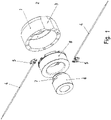
Figur 1 ist eine explodierte Darstellung einer Bremsspule für eine elektromagnetisch betätigbare Bremse gezeigt. - In der
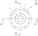
Figur 2 ist eine Vorderansicht der Bremsspule gezeigt. - In der
Figur 3 ist ein zugehöriger Längsschnitt gezeigt. - In der
Figur 4 ist ein zugehöriger Querschnitt gezeigt. - Wie in den Figuren gezeigt, weist ein Magnetkörper einer Bremsspule einer elektromagnetisch betätigbaren Bremse einen ringförmigen Außenpol 1 des Magnetkörpers auf und einen Rücken 2 des Magnetkörpers, wobei Außenpol 1 und Rücken 2 einstückig ausgeführt sind.
- Als Material des Magnetkörpers wird vorzugsweise ein ferromagnetisches Material eingesetzt, insbesondere beispielsweise ein ferromagnetischer Stahl oder ein Stahlguss, insbesondere Sphäroguss.
- Der Rücken 2 weist eine mittig angeordnete, insbesondere kreisförmige, Ausnehmung auf. Somit ist der Rücken 2 lochscheibenartig ausgeführt.
- Der Innenpol 6 ist im Wesentlichen zylindrisch ausgeführt und kraftschlüssig, insbesondere mittels Presspassung, mit dem Magnetkörper verbunden. Bei der Herstellung der Bremse wird der Innenpol 6 in die Ausnehmung im Rücken 2 eingepresst.
- Der Innenpol 6 ist aus einem Material ausgeführt, das eine höhere spezifische magnetische Permeabilität aufweist als der Außenpol 1 mit Rücken 2. Beispielsweise ist als Material des Innenpols 6 Ferrit oder ein anderes hochpermeables Material verwendbar. Auf diese Weise ist eine hohe Feldstärke im Innenpol 6 durchleitbar, ohne dass Sättigung einritt.
- Der Außenpol 1 weist eine axial verlaufende Vertiefung 3 zur Kabelführung, insbesondere zur Führung der Statorleitungen eines mit der Bremse verbundenen Elektromotors, auf. Somit sind die Statorwicklungsleitungen eines Elektromotors, an welchem die Bremse angebaut oder in welchen die Bremse eingebaut ist, platzsparend vorbeiführbar an der Bremse und von dort dann zu einem Anschlusskasten führbar, in welchem Versorgungsleitungen für Versorgung des Motors verbindbar sind. Außerdem sind auch die Versorgungsleitungen der Bremsspule vom Anschlusskasten zur Bremse als Bremsspulenwicklungsanschlussleitungen 4 zuführbar. Hierbei ist beispielsweise Litze als jeweilige Bremsspulenwicklungsanschlussleitung 4 verwendbar. Die Spulenwicklung 30 ist als Ringspulenwicklung ausgeführt und weist eine erste und eine weitere Bremsspulenwicklungsanschlussleitung 4 auf.
- Die Bremsspulenwicklungsanschlussleitungen 4 sind jeweils mit einem Anschlussteil 5 verbunden, insbesondere schweißverbunden. Das jeweilige Anschlussteil 5 ist vorzugsweise als Stanz-Biegeteil ausgeführt, insbesondere aus Kupferblech.
- An das jeweilige Anschlussteil 5 wird auch ein jeweiliges Ende des Wicklungsdrahtes der Bremsspulenwicklung 30 elektrisch verbunden. Die Bremsspulenwicklung 30 ist als Ringwicklung ausgeführt und in einem Spulenträger 8 aufgenommen. Der Spulenträger 8 ist aus Kunststoff ausgeführt, insbesondere als Spritzgussteil.
- Der Spulenträger 8 ist mittels eines Hinterschnitts 33 am Innenpol 6 gehalten, wobei der Innenpol 6 hierzu eine Stufe aufweist, also eine radiale Verdickung, welche axial beabstandet ist vom Verbindungsbereich zwischen Innenpol 6 und Magnetkörper, insbesondere Rücken 2.
- Der Spulenträger 8 weist eine entsprechende radiale Verdickung auf, die somit in den axialen Zwischenbereich zwischen der Verdickung des Innenpols 6 und dem Verbindungsbereich zwischen Innenpol 6 und Magnetkörper, insbesondere Rücken 2. Somit ist eine axiale Fixierung am Hinterschnitt 33 erreicht. In einen Aufnahmebereich 31 des Spulenträgers 8, der als Ausnehmung in der Verdickung des Spulenträgers 8 ausgebildet ist, ist das Anschlussteil 5 aufgenommen. Der Aufnahmebereich 31 ist als taschenförmiger Spulenkörperabschnitt zur Bildung des Aufnahmebereichs für Anschlussteil 5 und/oder Kabelführung ausgeführt. Außerdem ist am Spulenträger 8 eine umlaufende Nut gebildet, die zur Kabelführung dient und in die taschenförmige Spulenkörperabschnitte mündet.
- Mittels der Vertiefung 3 ist eine Kabelführung, insbesondere zur Führung der Statorleitungen, in axialer Richtung über den vom Magnetkörper überdeckten Axialbereich ermöglicht.
- Der Spulenträger 8 ist mittels Vergussmasse 40 vergossen im Aufnahmebereich zwischen Außenpol 1 und Innenpol 6.
- An demjenigen Umfangswinkelbereich, an welchem das Anschlussteil 5 in radialer Richtung nach radial innen am Spulenträger 8 eingeschoben wird, ragt das Anschlussteil 5 radial weiter nach innen als der innere Durchmesser des Spulenträgers 8. Im entsprechenden Umfangswinkelbereich weist der Innenpol 6 eine radiale Vertiefung auf, so dass das Anschlussteil 5 mit seinem radial inneren Endbereich aufliegt auf dem Innenpol 6.
- Der Innenpol 6 ist als Hohlzylindrisches Teil ausgeführt, so dass die Bremsrotorwelle axialdurch den Magnetkörper hindurchragen kann und auf der vom Motor abgewandten Seite der Bremse ein Winkelsensor verbindbar ist.
- Das Anschlussteil 5 ist auch als Kontakthaken bezeichenbar.
- Die Bremsspule wird mit Gleichstrom versorgt. Bei Bestromung wird eine mit dem Magnetkörper drehfest verbundene, axial bewegbar angeordnete, aus Stahl gefertigte Ankerscheibe der Bremse axial zum Magnetkörper hin bewegt entgegen der von am Magnetkörper abgestützten Federelementen erzeugten Federkraft. Bei Nicht-Bestromung wird die Ankerscheibe vom Magnetkörper weggedrückt und dabei gegen einen drehfest mit der Bremsrotorwelle verbundenen,
- Vorteiligerweise ist der Innenpol 6 und der Außenpol 1 aus verschiedenen Werkstoffen herstellbar. Der Innenpol 6 weist höhere Flussdichten auf als der Außenpol 1, wenn das Material des Innenpols 6 eine höhere zulässige Maximalinduktion und/oder steilere Magnetisierungskennlinie aufweist. Somit fallen weniger Eisenverluste und/oder Magnetisierungsverluste an
Vorzugsweise ist der Innenpol 6 aus einem Stangenmaterial auf einem Stangendrehautomaten gefertigt. - Da Außenpol 1 und Rücken 2 des Magnetkörpers eine topfartige Form aufweisen, ist eine einfache Herstellung durch Gießen und/oder Schmieden ermöglicht.
- Mittels des Hinterschnitts 33 ist nicht nur eine Fixierung des Spulenträgers 8 zwischen Innenpol 6 und Rücken 2 erreichbar sondern die Innenpolfläche ist größer dimensionierbar als ohne Ausbildung des Hinterschnitts 33. Somit verläuft die Kennlinie zwischen Magnetkraft und Luftspalt weniger steil, wobei der Luftspalt der axiale Abstand zwischen Ankerscheibe und Magnetkörper ist.
- Durch die Einpresstiefe des Innenpols 6 in den Rücken 2 des Magnetkörpers lässt sich die Einfallzeit der Bremse vorgeben, insbesondere in Abhängigkeit des Bremsmoments und/oder der Federelemente.
-
- 1 Außenpol des Magnetkörpers
- 2 Rücken des Magnetkörpers
- 3 Vertiefung zur Kabelführung, insbesondere zur Führung der Statorleitungen
- 4 Bremsspulenwicklungsanschlussleitung
- 5 Anschlussteil, insbesondere Stanz-Biegeteil
- 6 Innenpol
- 7 Abflachung
- 8 Spulenträger
- 30 Spulenwicklung
- 31 Aufnahmebereich für Anschlussteil 5
- 32 taschenförmiger Spulenkörperabschnitt zur Bildung des Aufnahmebereichs für Anschlussteil 5 und/oder Kabelführung
- 33 Hinterschnitt
- 40 Vergussmasse
Claims (11)
- Elektromagnet, insbesondere Bremsspule, insbesondere für eine elektromagnetisch betätigbare Bremse,wobei der Elektromagnet eine in einem Spulenträger (8) aufgenommene Spulenwicklung (30) aufweist,wobei der Spulenträger (8) in einem Magnetkörper aufgenommen ist,wobei der Magnetkörper zwei- oder mehrteilig aufgebaut ist,dadurch gekennzeichnet, dassein Innenpol (6) des Magnetkörpers aus einem ersten Material gefertigt ist und wobei der Außenpol (1) des Magnetkörpers aus einem zweiten Material gefertigt ist,wobei das erste Material eine höhere spezifische magnetische Permeabilität aufweist als das zweite Material,wobei der Innenpol (6) in ein anderes Teil des Magnetkörpers, insbesondere Rücken (2) des Magnetkörpers, eingepresst ist und/oder kraftschlüssig mit diesem Teil verbunden ist,wobei der Außenpol (1) des Magnetkörpers mit dem Rücken (2) des Magnetkörpers einstückig, also einteilig, ausgeführt ist,wobei der Innenpol (6) im Bereich der Verbindung mit dem anderen Teil des Magnetkörpers verjüngt ausgeführt ist, so dass ein Hinterschnitt (33) gebildet ist, in welchem der Spulenträger (8) mit Spulenwicklung (30) begrenzt ist, insbesondere zwischen Hinterschnitt (33) und Rücken (2) des Magnetkörpers.
- Elektromagnet nach Anspruch 1,
dadurch gekennzeichnet, dass
die Spulenwicklung (30) eine Ringwicklung ist. - Elektromagnet nach mindestens einem der vorangegangenen Ansprüche,
dadurch gekennzeichnet, dassdas erste Material ein Stahl oder ein Ferrit istund/oder dass das zweite Material ein Sphäroguss ist. - Elektromagnet nach mindestens einem der vorangegangenen Ansprüche,
dadurch gekennzeichnet, dass
der Spulenträger (8) samt Spulenwicklung (30) mittels Vergussmasse (40) im Magnetkörper vergossen ist. - Elektromagnet nach mindestens einem der vorangegangenen Ansprüche,
dadurch gekennzeichnet, dassein Anschlussteil (5), an welchem ein jeweiliges Ende des Spulenwicklungsdrahtes elektrisch verbunden ist und eine Versorgungsleitung, insbesondere eine Litzenleitung, in einen am Spulenträger (8) ausgebildeten taschenförmigen Aufnahmebereich (31) eingeschoben ist,insbesondere wobei der Innenpol (6) im vom Anschlussteil (5) überdeckten Umfangswinkelbereich eine Abflachung (7) aufweist. - Elektromagnet nach mindestens einem der vorangegangenen Ansprüche,
dadurch gekennzeichnet, dass
der Innenpol (6) im Wesentlichen zylindrisch ausgeformt ist. - Elektromagnet nach mindestens einem der vorangegangenen Ansprüche,
dadurch gekennzeichnet, dassder Außenpol (1) als Rotationskörper ausgebildet ist,insbesondere wobei eine Vertiefung (3) zur Führung von elektrischen Leitungen am Außenumfang des Außenpols (1) ausgeformt oder eingearbeitet ist und/oder an der einem Motor zugewandten axialen Stirnseite des Außenpols (1) Bohrlöcher, insbesondere in Umfangsrichtung regelmäßig voneinander beabstandete Bohrlöcher, ausgeformt oder eingearbeitet sind, insbesondere zur Aufnahme von Führungselementen zur Führung einer Ankerscheibe einer Bremse und/oder Beabstandungselementen, welche den Außenpol (1) zu dem mit dem Außenpol (1) verbindbaren Elektromotor beabstanden. - Elektromagnet nach mindestens einem der vorangegangenen Ansprüche,
dadurch gekennzeichnet, dass
der Spulenträger (8) ein Spritzgusskunststoffteil ist. - Elektromagnet nach mindestens einem der vorangegangenen Ansprüche,
dadurch gekennzeichnet, dass
am Spulenträger (8) ein in Umfangsrichtung umlaufender Kabelführungskanal ausgebildet ist. - Elektromagnetisch betätigbaren Bremse mit einem Elektromagnet nach mindestens einem der vorangegangenen Ansprüche.
- Bremsmotor
dadurch gekennzeichnet, dass
der Bremsmotor einen Elektromotor mit einer Elektromagnetisch betätigbaren Bremse nach dem vorhergehenden Anspruch umfasst.
Applications Claiming Priority (2)
| Application Number | Priority Date | Filing Date | Title |
|---|---|---|---|
| DE102012013350.2A DE102012013350C5 (de) | 2012-07-06 | 2012-07-06 | Elektromagnet, elektromagnetisch betätigbare Bremse und Bremsmotor |
| PCT/EP2013/001557 WO2014005664A1 (de) | 2012-07-06 | 2013-05-27 | Elektromagnet, elektromagnetisch betätigbaren bremse und bremsmotor |
Publications (3)
| Publication Number | Publication Date |
|---|---|
| EP2870613A1 EP2870613A1 (de) | 2015-05-13 |
| EP2870613B1 EP2870613B1 (de) | 2017-09-20 |
| EP2870613B2 true EP2870613B2 (de) | 2022-09-21 |
Family
ID=48539084
Family Applications (1)
| Application Number | Title | Priority Date | Filing Date |
|---|---|---|---|
| EP13726114.5A Active EP2870613B2 (de) | 2012-07-06 | 2013-05-27 | Elektromagnet, elektromagnetisch betätigbare bremse und bremsmotor |
Country Status (5)
| Country | Link |
|---|---|
| US (1) | US9945433B2 (de) |
| EP (1) | EP2870613B2 (de) |
| CN (1) | CN104428850B (de) |
| DE (1) | DE102012013350C5 (de) |
| WO (1) | WO2014005664A1 (de) |
Families Citing this family (10)
| Publication number | Priority date | Publication date | Assignee | Title |
|---|---|---|---|---|
| DE102012013350C5 (de) | 2012-07-06 | 2024-02-15 | Sew-Eurodrive Gmbh & Co Kg | Elektromagnet, elektromagnetisch betätigbare Bremse und Bremsmotor |
| US11874140B2 (en) * | 2016-02-17 | 2024-01-16 | Infineon Technologies Ag | Tapered magnet |
| CN105605125B (zh) * | 2016-02-25 | 2018-01-23 | 珠海格力节能环保制冷技术研究中心有限公司 | 一种制动器的定子结构、制造工艺及电磁制动器 |
| US10518761B2 (en) | 2016-07-01 | 2019-12-31 | Akebono Brake Industry Co., Ltd | Electric park brake with electromagnetic brake |
| DE102017000846B4 (de) * | 2017-01-31 | 2022-06-02 | Sew-Eurodrive Gmbh & Co Kg | Elektromagnetisch betätigbare Bremsanordnung zum Abbremsen einer drehbar gelagerten Welle |
| WO2019141342A1 (de) * | 2018-01-19 | 2019-07-25 | Sew-Eurodrive Gmbh & Co. Kg Abt. Ecg | Antriebsvorrichtung, aufweisend zumindest eine kupplung und eine welle |
| US11098774B2 (en) * | 2019-05-01 | 2021-08-24 | Ryan Kleefisch ProStar RC Products | System and method for electro-magnetic applied friction braking in a radio controlled model car |
| WO2021078403A1 (de) * | 2019-10-22 | 2021-04-29 | Sew-Eurodrive Gmbh & Co. Kg | Bremsanordnung und elektromotor mit einer bremsanordnung |
| WO2024227586A1 (de) | 2023-05-02 | 2024-11-07 | Sew-Eurodrive Gmbh & Co. Kg | Bremse zum abbremsen einer welle und bremsmotor mit bremse |
| DE102024111216A1 (de) * | 2023-05-11 | 2024-11-14 | Sew-Eurodrive Gmbh & Co. Kg | Drahtführungselement, Bremse zum Abbremsen einer Welle und Bremsmotor mit Bremse |
Citations (4)
| Publication number | Priority date | Publication date | Assignee | Title |
|---|---|---|---|---|
| DE1959460A1 (de) † | 1968-12-11 | 1970-07-09 | Cie Electro Mecanique S A | Hochfrequenzschaltschuetz |
| DE102007038848A1 (de) † | 2007-08-16 | 2009-02-19 | Dorma Gmbh + Co. Kg | Spulenkörper für einen Linearmotor-Stator für eine automatische Tür |
| DE202008008650U1 (de) † | 2008-06-27 | 2009-11-12 | Robert Bosch Gmbh | Magnetkern, Magnetbaugruppe sowie Kraftstoff-Injektor-Magnetventil |
| DE112007002205B4 (de) † | 2006-09-19 | 2014-09-11 | Toyota Jidosha Kabushiki Kaisha | Induktorkern und Induktor |
Family Cites Families (14)
| Publication number | Priority date | Publication date | Assignee | Title |
|---|---|---|---|---|
| US2273073A (en) | 1940-02-28 | 1942-02-17 | Empire Electric Brake Corp | Electromagnet |
| US3759097A (en) * | 1970-09-01 | 1973-09-18 | V Cushing | Electromagnetic water current meter |
| US4982825A (en) * | 1989-05-11 | 1991-01-08 | Sepal | Torque and air gap adjustment mechanism for spring engaged brake or clutch |
| JPH0735829B2 (ja) * | 1989-08-18 | 1995-04-19 | 株式会社日立製作所 | エレベータ |
| DE4424457A1 (de) * | 1994-07-12 | 1996-01-18 | Zahnradfabrik Friedrichshafen | Elektromagnetische Hysteresebremse |
| US5685398A (en) * | 1996-06-28 | 1997-11-11 | Rexnord Corporation | Fast response adjustable brake |
| DE19805171C2 (de) * | 1998-02-10 | 2000-08-03 | Daimler Chrysler Ag | Elektromagnet und Verwendung desselben |
| CN2798268Y (zh) | 2004-12-10 | 2006-07-19 | 北京首冶磁性材料科技有限公司 | 抗直流分量互感器用复合磁芯 |
| DE102006062302A1 (de) | 2006-12-27 | 2008-07-03 | Pintsch Bamag Antriebs- Und Verkehrstechnik Gmbh | Elektromagnetische Bremse, Elektromagnet für eine solche Bremse, Verfahren zur Herstellung des Elektromagneten sowie Spulenträger für einen solchen Elektromagneten und mit einem solchen Elektromagneten ausgerüstete Antriebseinheit und Seilwinde |
| CN201178011Y (zh) | 2008-03-13 | 2009-01-07 | 北京冶科电子器材有限公司 | 抗直流分量互感器用组合磁芯 |
| US20100305402A1 (en) * | 2009-05-29 | 2010-12-02 | Magnetecs,Inc. | Method and apparatus for magnetic waveguide forming a shaped field employing a magnetic aperture for guiding and controlling a medical device |
| CN102074333B (zh) | 2009-11-24 | 2013-06-05 | 台达电子工业股份有限公司 | 混合材料磁芯组、磁性元件及制法 |
| JP2011165977A (ja) | 2010-02-10 | 2011-08-25 | Sumitomo Electric Ind Ltd | リアクトル |
| DE102012013350C5 (de) | 2012-07-06 | 2024-02-15 | Sew-Eurodrive Gmbh & Co Kg | Elektromagnet, elektromagnetisch betätigbare Bremse und Bremsmotor |
-
2012
- 2012-07-06 DE DE102012013350.2A patent/DE102012013350C5/de active Active
-
2013
- 2013-05-27 CN CN201380036069.3A patent/CN104428850B/zh active Active
- 2013-05-27 US US14/411,019 patent/US9945433B2/en active Active
- 2013-05-27 WO PCT/EP2013/001557 patent/WO2014005664A1/de not_active Ceased
- 2013-05-27 EP EP13726114.5A patent/EP2870613B2/de active Active
Patent Citations (4)
| Publication number | Priority date | Publication date | Assignee | Title |
|---|---|---|---|---|
| DE1959460A1 (de) † | 1968-12-11 | 1970-07-09 | Cie Electro Mecanique S A | Hochfrequenzschaltschuetz |
| DE112007002205B4 (de) † | 2006-09-19 | 2014-09-11 | Toyota Jidosha Kabushiki Kaisha | Induktorkern und Induktor |
| DE102007038848A1 (de) † | 2007-08-16 | 2009-02-19 | Dorma Gmbh + Co. Kg | Spulenkörper für einen Linearmotor-Stator für eine automatische Tür |
| DE202008008650U1 (de) † | 2008-06-27 | 2009-11-12 | Robert Bosch Gmbh | Magnetkern, Magnetbaugruppe sowie Kraftstoff-Injektor-Magnetventil |
Also Published As
| Publication number | Publication date |
|---|---|
| US9945433B2 (en) | 2018-04-17 |
| US20150184704A1 (en) | 2015-07-02 |
| EP2870613B1 (de) | 2017-09-20 |
| DE102012013350A1 (de) | 2014-01-09 |
| WO2014005664A1 (de) | 2014-01-09 |
| CN104428850B (zh) | 2017-07-04 |
| DE102012013350B4 (de) | 2015-03-05 |
| DE102012013350C5 (de) | 2024-02-15 |
| EP2870613A1 (de) | 2015-05-13 |
| CN104428850A (zh) | 2015-03-18 |
Similar Documents
| Publication | Publication Date | Title |
|---|---|---|
| EP2870613B2 (de) | Elektromagnet, elektromagnetisch betätigbare bremse und bremsmotor | |
| DE102010064051A1 (de) | Wicklungsträger zur Isolation einer Einzelzahnwicklung bei elektrischen Maschinen | |
| DE102010017044A1 (de) | Elektromotor | |
| DE102015200086A1 (de) | Verschaltungsplatte für einen Stator einer elektrischen Maschine und Verfahren zum Herstellen einer solchen | |
| EP2807721B1 (de) | Elektromaschine | |
| DE10331245B4 (de) | Bürstenmotor für elektrisches Lenkservosystem | |
| EP1922799A1 (de) | Elektrischer antrieb mit topfförmigem anker und aussenliegenden permanentmagnetelementen | |
| DE102015209225A1 (de) | Stator einer elektrischen Maschine mit einer Verschaltungseinrichtung und elektrische Maschine mit einem solchen Stator | |
| DE102018201537B4 (de) | Elektromotor | |
| EP3391509B1 (de) | Elektromotor | |
| DE19709044C2 (de) | Linearmotor | |
| DE102006054979A1 (de) | Radnabendynamo | |
| WO2012022563A2 (de) | Elektrische maschine | |
| WO2015113584A1 (de) | Elektrische maschine | |
| DE102010014860B4 (de) | Spule und Bremse | |
| DE102015222642A1 (de) | Elektromotor | |
| WO2013072373A1 (de) | Induktiver drehübertrager | |
| DE102013000603B4 (de) | Bremsanordnung zum Abbremsen einer Welle | |
| WO2017194264A1 (de) | Stator einer elektrischen maschine mit einer verschaltungseinrichtung für statorspulen und elektrische maschine mit einem derartigen stator | |
| WO2024231088A1 (de) | Drahtführungselement, bremse zum abbremsen einer welle und bremsmotor mit bremse | |
| DE102013208175A1 (de) | Trägerelement für eine Erregerspule, elektrische Maschine sowie Verfahren zum Aufbau einer elektrischen Maschine | |
| DE102022208559A1 (de) | Rotor einer elektrischen Maschine | |
| DE102023212921A1 (de) | Rotor einer elektrischen Maschine | |
| DE102008013035A1 (de) | Verfahren zum Bewickeln eines Stators für eine Innenläufermaschine und Stator für eine Innenläufermaschine | |
| DE102006034049A1 (de) | Spule, Ansteuerung, Kontaktierung und Verfahren |
Legal Events
| Date | Code | Title | Description |
|---|---|---|---|
| PUAI | Public reference made under article 153(3) epc to a published international application that has entered the european phase |
Free format text: ORIGINAL CODE: 0009012 |
|
| 17P | Request for examination filed |
Effective date: 20150206 |
|
| AK | Designated contracting states |
Kind code of ref document: A1 Designated state(s): AL AT BE BG CH CY CZ DE DK EE ES FI FR GB GR HR HU IE IS IT LI LT LU LV MC MK MT NL NO PL PT RO RS SE SI SK SM TR |
|
| AX | Request for extension of the european patent |
Extension state: BA ME |
|
| DAX | Request for extension of the european patent (deleted) | ||
| GRAP | Despatch of communication of intention to grant a patent |
Free format text: ORIGINAL CODE: EPIDOSNIGR1 |
|
| STAA | Information on the status of an ep patent application or granted ep patent |
Free format text: STATUS: GRANT OF PATENT IS INTENDED |
|
| INTG | Intention to grant announced |
Effective date: 20170503 |
|
| GRAS | Grant fee paid |
Free format text: ORIGINAL CODE: EPIDOSNIGR3 |
|
| GRAA | (expected) grant |
Free format text: ORIGINAL CODE: 0009210 |
|
| STAA | Information on the status of an ep patent application or granted ep patent |
Free format text: STATUS: THE PATENT HAS BEEN GRANTED |
|
| AK | Designated contracting states |
Kind code of ref document: B1 Designated state(s): AL AT BE BG CH CY CZ DE DK EE ES FI FR GB GR HR HU IE IS IT LI LT LU LV MC MK MT NL NO PL PT RO RS SE SI SK SM TR |
|
| REG | Reference to a national code |
Ref country code: GB Ref legal event code: FG4D Free format text: NOT ENGLISH |
|
| REG | Reference to a national code |
Ref country code: CH Ref legal event code: EP Ref country code: CH Ref legal event code: NV Representative=s name: HEPP WENGER RYFFEL AG, CH |
|
| REG | Reference to a national code |
Ref country code: AT Ref legal event code: REF Ref document number: 930760 Country of ref document: AT Kind code of ref document: T Effective date: 20171015 |
|
| REG | Reference to a national code |
Ref country code: IE Ref legal event code: FG4D Free format text: LANGUAGE OF EP DOCUMENT: GERMAN |
|
| REG | Reference to a national code |
Ref country code: DE Ref legal event code: R096 Ref document number: 502013008400 Country of ref document: DE |
|
| REG | Reference to a national code |
Ref country code: NL Ref legal event code: MP Effective date: 20170920 |
|
| PG25 | Lapsed in a contracting state [announced via postgrant information from national office to epo] |
Ref country code: NO Free format text: LAPSE BECAUSE OF FAILURE TO SUBMIT A TRANSLATION OF THE DESCRIPTION OR TO PAY THE FEE WITHIN THE PRESCRIBED TIME-LIMIT Effective date: 20171220 Ref country code: SE Free format text: LAPSE BECAUSE OF FAILURE TO SUBMIT A TRANSLATION OF THE DESCRIPTION OR TO PAY THE FEE WITHIN THE PRESCRIBED TIME-LIMIT Effective date: 20170920 Ref country code: FI Free format text: LAPSE BECAUSE OF FAILURE TO SUBMIT A TRANSLATION OF THE DESCRIPTION OR TO PAY THE FEE WITHIN THE PRESCRIBED TIME-LIMIT Effective date: 20170920 Ref country code: HR Free format text: LAPSE BECAUSE OF FAILURE TO SUBMIT A TRANSLATION OF THE DESCRIPTION OR TO PAY THE FEE WITHIN THE PRESCRIBED TIME-LIMIT Effective date: 20170920 Ref country code: LT Free format text: LAPSE BECAUSE OF FAILURE TO SUBMIT A TRANSLATION OF THE DESCRIPTION OR TO PAY THE FEE WITHIN THE PRESCRIBED TIME-LIMIT Effective date: 20170920 |
|
| REG | Reference to a national code |
Ref country code: LT Ref legal event code: MG4D |
|
| PG25 | Lapsed in a contracting state [announced via postgrant information from national office to epo] |
Ref country code: LV Free format text: LAPSE BECAUSE OF FAILURE TO SUBMIT A TRANSLATION OF THE DESCRIPTION OR TO PAY THE FEE WITHIN THE PRESCRIBED TIME-LIMIT Effective date: 20170920 Ref country code: BG Free format text: LAPSE BECAUSE OF FAILURE TO SUBMIT A TRANSLATION OF THE DESCRIPTION OR TO PAY THE FEE WITHIN THE PRESCRIBED TIME-LIMIT Effective date: 20171220 Ref country code: RS Free format text: LAPSE BECAUSE OF FAILURE TO SUBMIT A TRANSLATION OF THE DESCRIPTION OR TO PAY THE FEE WITHIN THE PRESCRIBED TIME-LIMIT Effective date: 20170920 Ref country code: GR Free format text: LAPSE BECAUSE OF FAILURE TO SUBMIT A TRANSLATION OF THE DESCRIPTION OR TO PAY THE FEE WITHIN THE PRESCRIBED TIME-LIMIT Effective date: 20171221 |
|
| PG25 | Lapsed in a contracting state [announced via postgrant information from national office to epo] |
Ref country code: NL Free format text: LAPSE BECAUSE OF FAILURE TO SUBMIT A TRANSLATION OF THE DESCRIPTION OR TO PAY THE FEE WITHIN THE PRESCRIBED TIME-LIMIT Effective date: 20170920 |
|
| REG | Reference to a national code |
Ref country code: FR Ref legal event code: PLFP Year of fee payment: 6 |
|
| PG25 | Lapsed in a contracting state [announced via postgrant information from national office to epo] |
Ref country code: PL Free format text: LAPSE BECAUSE OF FAILURE TO SUBMIT A TRANSLATION OF THE DESCRIPTION OR TO PAY THE FEE WITHIN THE PRESCRIBED TIME-LIMIT Effective date: 20170920 Ref country code: CZ Free format text: LAPSE BECAUSE OF FAILURE TO SUBMIT A TRANSLATION OF THE DESCRIPTION OR TO PAY THE FEE WITHIN THE PRESCRIBED TIME-LIMIT Effective date: 20170920 Ref country code: RO Free format text: LAPSE BECAUSE OF FAILURE TO SUBMIT A TRANSLATION OF THE DESCRIPTION OR TO PAY THE FEE WITHIN THE PRESCRIBED TIME-LIMIT Effective date: 20170920 Ref country code: ES Free format text: LAPSE BECAUSE OF FAILURE TO SUBMIT A TRANSLATION OF THE DESCRIPTION OR TO PAY THE FEE WITHIN THE PRESCRIBED TIME-LIMIT Effective date: 20170920 |
|
| PG25 | Lapsed in a contracting state [announced via postgrant information from national office to epo] |
Ref country code: IT Free format text: LAPSE BECAUSE OF FAILURE TO SUBMIT A TRANSLATION OF THE DESCRIPTION OR TO PAY THE FEE WITHIN THE PRESCRIBED TIME-LIMIT Effective date: 20170920 Ref country code: SM Free format text: LAPSE BECAUSE OF FAILURE TO SUBMIT A TRANSLATION OF THE DESCRIPTION OR TO PAY THE FEE WITHIN THE PRESCRIBED TIME-LIMIT Effective date: 20170920 Ref country code: EE Free format text: LAPSE BECAUSE OF FAILURE TO SUBMIT A TRANSLATION OF THE DESCRIPTION OR TO PAY THE FEE WITHIN THE PRESCRIBED TIME-LIMIT Effective date: 20170920 Ref country code: IS Free format text: LAPSE BECAUSE OF FAILURE TO SUBMIT A TRANSLATION OF THE DESCRIPTION OR TO PAY THE FEE WITHIN THE PRESCRIBED TIME-LIMIT Effective date: 20180120 Ref country code: SK Free format text: LAPSE BECAUSE OF FAILURE TO SUBMIT A TRANSLATION OF THE DESCRIPTION OR TO PAY THE FEE WITHIN THE PRESCRIBED TIME-LIMIT Effective date: 20170920 |
|
| REG | Reference to a national code |
Ref country code: DE Ref legal event code: R026 Ref document number: 502013008400 Country of ref document: DE |
|
| PLBI | Opposition filed |
Free format text: ORIGINAL CODE: 0009260 |
|
| PLAX | Notice of opposition and request to file observation + time limit sent |
Free format text: ORIGINAL CODE: EPIDOSNOBS2 |
|
| 26 | Opposition filed |
Opponent name: INTORQ GMBH & CO. KG Effective date: 20180619 |
|
| PG25 | Lapsed in a contracting state [announced via postgrant information from national office to epo] |
Ref country code: DK Free format text: LAPSE BECAUSE OF FAILURE TO SUBMIT A TRANSLATION OF THE DESCRIPTION OR TO PAY THE FEE WITHIN THE PRESCRIBED TIME-LIMIT Effective date: 20170920 |
|
| PLBB | Reply of patent proprietor to notice(s) of opposition received |
Free format text: ORIGINAL CODE: EPIDOSNOBS3 |
|
| PG25 | Lapsed in a contracting state [announced via postgrant information from national office to epo] |
Ref country code: MT Free format text: LAPSE BECAUSE OF FAILURE TO SUBMIT A TRANSLATION OF THE DESCRIPTION OR TO PAY THE FEE WITHIN THE PRESCRIBED TIME-LIMIT Effective date: 20170920 |
|
| PG25 | Lapsed in a contracting state [announced via postgrant information from national office to epo] |
Ref country code: SI Free format text: LAPSE BECAUSE OF FAILURE TO SUBMIT A TRANSLATION OF THE DESCRIPTION OR TO PAY THE FEE WITHIN THE PRESCRIBED TIME-LIMIT Effective date: 20170920 |
|
| REG | Reference to a national code |
Ref country code: BE Ref legal event code: MM Effective date: 20180531 |
|
| PG25 | Lapsed in a contracting state [announced via postgrant information from national office to epo] |
Ref country code: MC Free format text: LAPSE BECAUSE OF FAILURE TO SUBMIT A TRANSLATION OF THE DESCRIPTION OR TO PAY THE FEE WITHIN THE PRESCRIBED TIME-LIMIT Effective date: 20170920 |
|
| REG | Reference to a national code |
Ref country code: IE Ref legal event code: MM4A |
|
| PG25 | Lapsed in a contracting state [announced via postgrant information from national office to epo] |
Ref country code: LU Free format text: LAPSE BECAUSE OF NON-PAYMENT OF DUE FEES Effective date: 20180527 |
|
| PG25 | Lapsed in a contracting state [announced via postgrant information from national office to epo] |
Ref country code: IE Free format text: LAPSE BECAUSE OF NON-PAYMENT OF DUE FEES Effective date: 20180527 |
|
| PG25 | Lapsed in a contracting state [announced via postgrant information from national office to epo] |
Ref country code: BE Free format text: LAPSE BECAUSE OF NON-PAYMENT OF DUE FEES Effective date: 20180531 |
|
| PG25 | Lapsed in a contracting state [announced via postgrant information from national office to epo] |
Ref country code: TR Free format text: LAPSE BECAUSE OF FAILURE TO SUBMIT A TRANSLATION OF THE DESCRIPTION OR TO PAY THE FEE WITHIN THE PRESCRIBED TIME-LIMIT Effective date: 20170920 |
|
| PG25 | Lapsed in a contracting state [announced via postgrant information from national office to epo] |
Ref country code: PT Free format text: LAPSE BECAUSE OF FAILURE TO SUBMIT A TRANSLATION OF THE DESCRIPTION OR TO PAY THE FEE WITHIN THE PRESCRIBED TIME-LIMIT Effective date: 20170920 |
|
| PG25 | Lapsed in a contracting state [announced via postgrant information from national office to epo] |
Ref country code: MK Free format text: LAPSE BECAUSE OF NON-PAYMENT OF DUE FEES Effective date: 20170920 Ref country code: CY Free format text: LAPSE BECAUSE OF FAILURE TO SUBMIT A TRANSLATION OF THE DESCRIPTION OR TO PAY THE FEE WITHIN THE PRESCRIBED TIME-LIMIT Effective date: 20170920 Ref country code: HU Free format text: LAPSE BECAUSE OF FAILURE TO SUBMIT A TRANSLATION OF THE DESCRIPTION OR TO PAY THE FEE WITHIN THE PRESCRIBED TIME-LIMIT; INVALID AB INITIO Effective date: 20130527 |
|
| PG25 | Lapsed in a contracting state [announced via postgrant information from national office to epo] |
Ref country code: AL Free format text: LAPSE BECAUSE OF FAILURE TO SUBMIT A TRANSLATION OF THE DESCRIPTION OR TO PAY THE FEE WITHIN THE PRESCRIBED TIME-LIMIT Effective date: 20170920 |
|
| PUAH | Patent maintained in amended form |
Free format text: ORIGINAL CODE: 0009272 |
|
| STAA | Information on the status of an ep patent application or granted ep patent |
Free format text: STATUS: PATENT MAINTAINED AS AMENDED |
|
| 27A | Patent maintained in amended form |
Effective date: 20220921 |
|
| AK | Designated contracting states |
Kind code of ref document: B2 Designated state(s): AL AT BE BG CH CY CZ DE DK EE ES FI FR GB GR HR HU IE IS IT LI LT LU LV MC MK MT NL NO PL PT RO RS SE SI SK SM TR |
|
| REG | Reference to a national code |
Ref country code: DE Ref legal event code: R102 Ref document number: 502013008400 Country of ref document: DE |
|
| REG | Reference to a national code |
Ref country code: FR Ref legal event code: PLFP Year of fee payment: 11 |
|
| PGFP | Annual fee paid to national office [announced via postgrant information from national office to epo] |
Ref country code: DE Payment date: 20250531 Year of fee payment: 13 |
|
| PGFP | Annual fee paid to national office [announced via postgrant information from national office to epo] |
Ref country code: GB Payment date: 20250401 Year of fee payment: 13 |
|
| PGFP | Annual fee paid to national office [announced via postgrant information from national office to epo] |
Ref country code: FR Payment date: 20250401 Year of fee payment: 13 |
|
| PGFP | Annual fee paid to national office [announced via postgrant information from national office to epo] |
Ref country code: CH Payment date: 20250601 Year of fee payment: 13 |
|
| PGFP | Annual fee paid to national office [announced via postgrant information from national office to epo] |
Ref country code: AT Payment date: 20250508 Year of fee payment: 13 |