EP2870427B1 - Vorrichtung zum abschiessen von zielen für sportschiessen mit sofortigem abheben des ziels - Google Patents
Vorrichtung zum abschiessen von zielen für sportschiessen mit sofortigem abheben des ziels Download PDFInfo
- Publication number
- EP2870427B1 EP2870427B1 EP13732193.1A EP13732193A EP2870427B1 EP 2870427 B1 EP2870427 B1 EP 2870427B1 EP 13732193 A EP13732193 A EP 13732193A EP 2870427 B1 EP2870427 B1 EP 2870427B1
- Authority
- EP
- European Patent Office
- Prior art keywords
- arm
- launching
- rotation
- stop
- target
- Prior art date
- Legal status (The legal status is an assumption and is not a legal conclusion. Google has not performed a legal analysis and makes no representation as to the accuracy of the status listed.)
- Active
Links
- 230000009471 action Effects 0.000 claims description 7
- 238000000034 method Methods 0.000 description 10
- 230000000903 blocking effect Effects 0.000 description 6
- 208000031968 Cadaver Diseases 0.000 description 3
- 230000001133 acceleration Effects 0.000 description 3
- 230000000295 complement effect Effects 0.000 description 3
- 230000007257 malfunction Effects 0.000 description 3
- 230000008901 benefit Effects 0.000 description 2
- 239000004927 clay Substances 0.000 description 2
- 210000002445 nipple Anatomy 0.000 description 2
- 230000004044 response Effects 0.000 description 2
- 230000001755 vocal effect Effects 0.000 description 2
- 241000272201 Columbiformes Species 0.000 description 1
- 230000005540 biological transmission Effects 0.000 description 1
- 230000003247 decreasing effect Effects 0.000 description 1
- 230000007547 defect Effects 0.000 description 1
- 230000010339 dilation Effects 0.000 description 1
- 238000006073 displacement reaction Methods 0.000 description 1
- 230000000694 effects Effects 0.000 description 1
- 239000006260 foam Substances 0.000 description 1
- 230000000977 initiatory effect Effects 0.000 description 1
- 230000007246 mechanism Effects 0.000 description 1
- 230000004048 modification Effects 0.000 description 1
- 238000012986 modification Methods 0.000 description 1
- 230000009467 reduction Effects 0.000 description 1
- 238000005096 rolling process Methods 0.000 description 1
- 238000004904 shortening Methods 0.000 description 1
Images


Classifications
-
- F—MECHANICAL ENGINEERING; LIGHTING; HEATING; WEAPONS; BLASTING
- F41—WEAPONS
- F41J—TARGETS; TARGET RANGES; BULLET CATCHERS
- F41J9/00—Moving targets, i.e. moving when fired at
- F41J9/16—Clay-pigeon targets; Clay-disc targets
- F41J9/18—Traps or throwing-apparatus therefor
- F41J9/20—Traps or throwing-apparatus therefor with spring-operated throwing arm
- F41J9/24—Traps or throwing-apparatus therefor with spring-operated throwing arm cocked by electromechanical means
Definitions
- the present invention relates to a target launching device for instantaneous shooting of the target, that is with the fastest possible launch of the target once the launch order has been given. .
- Target launching devices for sport shooting are known, these targets being in particular in the form of clay trays.
- One of these devices is disclosed, for example, by the document FR-A-2,787,181 .
- Such devices have given satisfaction in general but are not suitable for certain shooting disciplines when a quasi-instantaneous departure of the target is requested, this departure following for example the vocal order of the shooter.
- a device according to the preamble of independent claim 1 is disclosed in the document FR 2,238,136 .
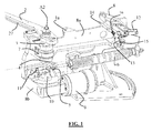
- the figure 1 shows a device for launching the state of the art according to an embodiment allowing an instantaneous departure.
- a target to launch not represented at the figure 1 is propelled by a rotating arm 2 provided with a strip 27 of rubber.
- the target is positioned mid-arm length 2 against the strip 27.
- the arm 2 is articulated about a substantially vertical axis A2 by being fixed to the upper end of a shaft 3 supported by a cross member 8a carried by the upper body 8 of the device 1a, said shaft 3 being free in rotation relative to 8.
- the arm 2 rotates about said axis A2 and undergoes an angular acceleration which plates the target against the strip 27, while rolling it towards its end. The target is then ejected by turning on itself.
- the arm 2 is indirectly secured via the shaft 3 of a rod 4 rotating about the axis A2, one end of the connecting rod 4 being connected to the lower end of the shaft 3.
- the rod 4 comprises at its other opposite end a pin 5 disposed on the side of the connecting rod not facing the arm 2 and projecting downwards.
- This stud 5 of the connecting rod 4 is secured to one end of a tension spring 6, the other end of the tension spring 6 being secured to the upper body 8 of the device 1 a.
- the rod 4 is also mechanically connected to a free wheel 7 mounted on the shaft 3.
- a geared motor 9 is carried by the lower body 8b of the device 1a.
- This geared motor 9 drives in rotation, through said lower body 8b, a crankpin 10 whose axis of rotation is coaxial with the axis of rotation A2 of the rod 4 and the arm 2.
- On the crankpin 10 there is provided a pin 11, protruding above the crank pin 10 and whose trajectory during the rotation of the crank pin 10 meets that of the pin 5 disposed at the end of the rod 4, this end being non-adjacent to the shaft 3.
- the two nipples 11 and 5 interfere with each other, this advantageously over a height of about 3 millimeters.
- a contactor 12 which coincides with the trajectory of a portion of the arm 2 when it has turned around its axis A2, this portion being advantageously the end portion of the arm 2.
- the arm 2 is rotatable about the upper body 8 and lower 8b of the device 1a, the rotation of the arm 2 is advantageously in the trigonometric direction with the freewheel 7 preventing any rotation of the arm 2 contrary.
- a remote triggering means instructs the geared motor 9 to turn.
- the crank pin 10 rotates about the axis coaxial with the axis of rotation A2 of the arm 2 and the stud 11 moves until it comes into contact with the stud 5 carried by the connecting rod 4, advantageously in linear contact.
- the rod 4, the shaft 3 and the arm 2 are then rotated to the stop of the arm 2 against the contactor 12. Ideally, this stop is as close as possible to a position called "zero point".
- the arm undergoes no torque from which obtaining a balance between the arming step and the launching step.
- the geared motor 9 is stopped when the arm 2 is beyond the "zero point" so as to ensure an immediate trigger the launch order. This position is called the launch position.
- the balance of the system is then a forced balance and is obtained by adding a movable obstacle on the trajectory of the arm 2.
- This obstacle consists of a trigger 13 pivoting about an axis 14.
- the trigger 13 is kept in contact with an electromagnet rod 15 by means of a return spring 16.
- a possible consequence is a locking of the trigger 13 in the open position, the arm 2 starting burst. Human intervention is necessary to avoid launching a target unnecessarily.
- Document is also known FR-A-2238136 a target launching device with a mechanical device for holding the launch arm of the targets before the launch order.
- This device employs a stop member carried directly by the drive shaft of the arm.
- the object of the present invention is to design a target launching device which can have a quasi-instantaneous response time to a launch order while improving the security and arming time problems of the devices of the state of the technique.
- the invention proposes a target launch device comprising a launching arm rotatable, launching means and motor means for arming the arm by rotation of said arm to a position called “point zero ", for which the launching means are under tension without exerting torque on the arm, characterized in that it comprises means for blocking in abutment with the displacement of the arm, carried by the drive means and complementary locking means carried by the arm, the abutment locking means and the complementary locking means being configured to lock the arm beyond the "zero point" on a predefined angular sector in the direction of rotation of the arm in a launch position for which the means traction launch exert a torque on the arm and to release the arm beyond the launch position for which the launching means are relaxed in order to rotate arm 2 to launch the target.
- the technical effect is a quasi-instantaneous departure of the target when the motor means substantially exceed the "zero point" and the locking means cease to be operational.
- the solution proposed by the present invention has the advantage of proposing a short arming step with a launch delay of the target in the shortest possible launch order,
- the locking means may be, in their operation and positioning, adjusted so as to avoid being able to play only on a small range of positions relative to means for locking the arm and the stop.
- the use of such a configuration for launch adjustment purposes is particularly advantageous.
- the stopping of the motor means is achieved before the arm is locked in the launch position.
- the method comprises a step of maintaining the position of the arm in its final rotational position after launching, said final position serving as the starting position for the arming step of a new launching cycle.
- the launching of targets can be done substantially in the air with a significant vertical component or substantially flush with a large horizontal component.
- the term "worn" means that the two elements are kinematically connected. All configurations respecting this kinematic simultaneity fall within the object of the invention. Both elements can be directly or indirectly related.
- the device 1 of the invention incorporates certain characteristics of the device of the figure 1 but for this device 1, the nipples 5 and 11 shown in FIG. figure 1 are replaced by a set of gears 17, 18 and a chain 19 or a belt with modification of the positioning of the geared motor 9 accordingly.
- the rod 4 has one end connected to the shaft 3 while its other end has a pivot 5a hinge with one end of the spring 6 traction, the other end of the tension spring 6 being connected to the point 28 of the upper body 8 of the device 1 b.
- the drive assembly specific to this embodiment comprises a geared motor 9 driving a drive pinion 18 itself connected by a transmission of the chain 19 or belt type to a pinion 17 carried by the shaft 3. Freewheeling 7 of the shaft 3 cooperates with the pinion 17.
- the geared motor 9 is arranged so that its output axis A1 is distant and parallel to the axis of rotation A2 of the arm 2. At the output end of the geared motor 9 is it finds the drive pinion 18 of smaller size than the pinion 17 and connected to the latter by means of the chain 19.
- a switch 12 is in the rotating path of the arm 2.
- a remote tripping device orders the gearmotor 9 to turn, the pinion 18 driving the pinion 17 through the chain 19.
- the device 1 comprises a connecting rod 4 connected to the lower end of the shaft 3 of rotation of the arm 2 rotating about an axis A2.
- the connecting rod 4 is articulated at its other end by a pivot 5a with one end of the spring 6 traction.
- the spring 6 of traction serving as launching means and substantially of elongate rectilinear shape, has its other end secured to the lower portion of the upper body 8 of the device 1 referenced 28.
- the axes X1, X2 respectively of the rod 4 and the spring 6 are shown in Figures 8 to 13 .
- the axis X3 illustrates the straight line passing through the center of the connecting rod 4 and the point 28 between the spring 6 and the body 8.
- zero point of the device 1 illustrated in figure 11 , in which the axis X3 and the axis X1 of the rod 4 are in the extension of one another, the axis X1 is superimposed on the axis X2; the rod 4 is above the spring 6 traction.
- No couple is exercised on the arm 2 because of the alignment of the forces and their passage through the axis of rotation of the arm, it is a position of equilibrium.
- This "zero point” position corresponds to the end of arming position, for which the traction spring 6 is likely to relax and the device 1 to then launch a target.
- This position, illustrated in figure 11 is, with reference to the trigonometric sense, just before the position shown figures 4 and 12 .
- the position of the arm 2 has slightly exceeded the "zero point". This position is called launch position.
- the launch position is located at an angular sector of 5 to 10 ° after the zero point in the direction of rotation of the arm.
- the step of arming the arm 2 of the device 1 can start from a starting position shown in FIGS. figures 3 and 9 .
- the inertia of the arm 2 made it exceed the rest position shown in FIG. figures 2 and 8 to complete its rotation in the position shown at figures 3 and 9 , approximately 270 ° from the "zero point".
- the arm 2 is maintained in this starting position which shortens the arming step relative to a starting arming step of the home position. This shortening is due to the action of the free wheel 7 associated with the shaft 3 of rotation of the arm 2 and disposed above the pinion 17 which holds the arm 2 in this position before the arming step.
- the arm 2 performs a rotation driven by the geared motor 9 to the "zero point" in the trigonometric direction. It is of course possible to design a device with a rotating arm in the other direction.
- the geared motor 9 drives via the pinion driving 18 the pinion 17 of the shaft 3 of rotation of the arm 2 and rotates said shaft 3 while the spring 6 of traction, illustrating the launching means of the device 1, tends .
- the launching method provides for a cut-off of the geared motor 9 as soon as the "zero point" has been crossed.
- the cut-off of the geared motor 9 can be made possible by the contactor 12 carried by the upper body 8 of the device 1, this switch 12 can interrupt the supply of the geared motor 9 when contacted by the end of the arm 2.
- the switch 12 is substantially positioned to be in contact with the arm 2 "at the zero point".
- the inertia of the arm 2 drives it beyond the "zero point” at the launch point, alternatively the switch 12 can delay the stop of the geared motor 9 to bring the arm 2 into the launch position.
- the cut can precede or be simultaneous with the locking of the launching means under tension. In this configuration, the device 1 is waiting for a target launch order
- the gearmotor 9 is restarted and the method according to the invention comprises a step of driving the device 1 by the geared motor 9, this step ending with the release of the launching means under tension of their blocking.
- the locking means of the launching means in the form of the traction spring 6 are means operating on the arm 2 and have the following characteristics with reference to the Figures 2 to 7 .
- crankpin 21 On the output shaft of the geared motor 9 rotating about the axis A1, above the drive pinion 18, there is provided a pin 21 with a free wheel 20 in its interior.
- the freewheel 20 allows the rotation of the crankpin 21 in the clockwise direction or if the latter is blocked, the rotation of the gearmotor 9 in the trigonometrical direction.
- the crankpin 21 carries at its periphery an axis 22, the axis 22 being eccentric with respect to the axis A1 of the gearmotor 9.
- a roller 23, free in rotation, is mounted on the axis 22, thus turning around a substantially vertical axis.
- An elastic means in the form of a spring 24, connected at one of its ends to the upper body 8 of the device 1 and the other to the lower part of the axis 22, maintains the lower portion of the shaft 22 against a stop 25.
- the spring 24 can press the edge of the crankpin 21 against the abutment 25.
- a lug 26 Toward the free end of the launch arm 2 and on its lower face, is fixed a lug 26.
- the roller 23 is in the trajectory of the lug 26 during the rotation of the arm 2 about the axis A2.
- the axis A2 of the pinion 17 and rotation of the arm 2, the axis A1 of the driving pinion 18 and the geared motor 9 and the axis 22 are arranged in this order.
- the switch 12 is in the path of the arm 2.
- the arm 2 at the end of the arming phase of the arm 2, the arm 2 reaches the "zero point” position and crosses it.
- the free end of the arm 2 switches the contactor 12 which cuts off the supply of the geared motor 9.
- the "zero point” has been crossed, the traction exerted by the tension spring 6 brings into contact the lug 26 of the arm 2 with the roller 23.
- the gearmotor 9 stopped, the freewheel 20 opposes the movement of the crankpin 21. This is shown in FIGS. figures 4 and 12 .
- the dimensions of the pinions 17 and 18 make it possible to create a reduction which limits the pressure of the pin 26 on the roller 23.
- the launching method according to the invention thus comprises a launching step by ejection of the target of the arm 2, this during the automatic expansion of the launching means formed by the traction spring 6, no blocking means do not hold them anymore then in tension position.
- This launching step by ejection of the target continues consecutively by the positions shown in FIGS. Figures 6 and 7 and 13 likewise only by the rest position shown to figures 2 and 8 .
- This rest position shown to figures 2 and 8 is exceeded, the arm 2 arriving, because of its inertia, in the position shown to figures 3 and 9 .
- This position is maintained to be the starting position of a new target launch by rotation in the trigonometric direction of the launch arm 2.
Landscapes
- Engineering & Computer Science (AREA)
- General Engineering & Computer Science (AREA)
- Portable Nailing Machines And Staplers (AREA)
- Toys (AREA)
- Transmission Devices (AREA)
- Telescopes (AREA)
- Aiming, Guidance, Guns With A Light Source, Armor, Camouflage, And Targets (AREA)
Claims (10)
- Vorrichtung (1) zum Abschießen von Zielen, einen in Drehrichtung beweglichen Abschussarm (2), Abschussmittel (6) und Motormittel (9) umfassend, die zum Spannen des Arms (2) durch Verdrehen des besagten Arms (2) bis in eine "Nullpunkt" genannte Position bestimmt sind, bei der die Abschussmittel (6) unter Zug stehen, ohne ein Moment auf den Arm (2) auszuüben, wobei die Vorrichtung (1) Mittel zum Blockieren (20 bis 23) der Bewegung des Arms (2) auf Anschlag, sowie ergänzende Mittel zum Blockieren (26) umfasst, wobei die Mittel zum Blockieren (20 bis 23) auf Anschlag und die ergänzenden Mittel zum Blockieren (26) konfiguriert sind, um den Arm (2) über den "Nullpunkt" hinaus in einem vordefinierten Winkelabschnitt in einer Drehrichtung des Arms (2) in einer Abschussposition zu blockieren, bei der die unter Zug befindlichen Abschussmittel ein Moment auf den Arm (2) ausüben, und um den Arm (2) über die Abschussposition hinaus freizugeben, bei der sich die Abschussmittel entspannen, um die Rotation des Arms (2) für den Abschuss des Ziels durchzuführen, und wobei der Abschussarm (2) eine Rotationswelle (3) umfasst,
dadurch gekennzeichnet, dass die Mittel zum Blockieren der Bewegung des Arms (2) auf Anschlag von den Motormitteln (9) getragen werden, die ergänzenden Mittel zum Blockieren vom Arm (2) getragen werden, wobei die besagte Welle (3) ein Ritzel (17) trägt, das durch ein zweites Antriebsritzel (18) angetrieben wird, das mit der Ausgangsachse (A1) der Motormittel (9) verbunden ist, die einen Getriebemotor (9) umfassen, und die Mittel zum Blockieren (20 bis 23) auf Anschlag einen Anschlag (23) umfassen, der am Umkreis eines Zapfens (21) getragen wird, der sich um die Ausgangsachse (A1) des Getriebemotors (9) dreht. - Vorrichtung (1) nach dem vorherigen Anspruch, wobei der Zapfen (21) auf einem Freilauf (20) montiert ist, wobei der besagte Freilauf (20) die Drehung des Zapfens (21) in die entgegengesetzte Richtung zur Drehung des Getriebemotors (9) ermöglicht.
- Vorrichtung (1) nach einem der vorherigen Ansprüche, wobei der Anschlag (23) des Zapfens (21) von einer im Verhältnis zur Ausgangsachse (A1) des Getriebemotors (9) außermittigen Achse (22) getragen wird, wobei sich der besagte Anschlag in Form einer Rolle (23) darstellt, die sich am oberen Ende der außermittigen Achse (22) dreht.
- Vorrichtung (1) nach einem der drei vorherigen Ansprüche, wobei sich die vom Arm (2) getragenen ergänzenden Mittel zum Blockieren, in Form eines Nockens (26) darstellen, der in Kontakt mit dem Anschlag (23) tritt, der bei der Drehung des Arms (2) nach dem "Nullpunkt" am Umfang des Zapfens (21) getragen wird.
- Vorrichtung (1) nach einem der vorherigen Ansprüche, wobei der Antrieb zwischen den beiden Ritzeln (17, 18) durch eine Kette (19) oder einen Riemen ausgeführt wird, die sich um die besagten Ritzel (17, 18) drehen.
- Vorrichtung nach einem der vorherigen Ansprüche, wobei in das von der Rotationswelle (3) des Arms (2) getragene Ritzel (17) ein Freilauf (7) eingeführt wird, wobei sich der äußere Käfig des Freilaufs (7) in die Drehrichtung des Arms (2) dreht.
- Vorrichtung (1) nach irgendeinem der vorherigen Ansprüche, einen feststehenden Korpus (8, 8a, 8b) umfassend, einen Anschlag (25), der fest mit dem besagten Korpus (8, 8a, 8b) verbunden ist, da er an der Kante des Zapfens (21) anliegt.
- Vorrichtung (1) nach dem vorherigen Anspruch, wobei der Anschlag (25) unter Einwirkung eines elastischen Mittels (24) an die Kante des Zapfens (21) gedrückt wird.
- Vorrichtung (1) nach irgendeinem der vorherigen Ansprüche, wobei sich die Abschussmittel in Form einer Zugfeder (6) darstellen, die imstande ist, bei der Drehung des Arms (2) gespannt zu werden, wobei die Rückführung in die entspannte Position der Zugfeder (6) die Drehung des Arms (2) zum Abschießen des Ziels durch den Arm (2) durchführt.
- Vorrichtung (1) nach dem vorherigen Anspruch, wobei die Zugfeder (6) an einem ihrer Enden am Korpus (8) der Vorrichtuung (1) befestigt ist, wobei ihr anderes Ende drehend an einem Ende einer Kurbelstange (4) angebracht ist, deren anderes Ende mit der Rotationswelle (3) des Arms (2) verbunden ist.
Applications Claiming Priority (2)
| Application Number | Priority Date | Filing Date | Title |
|---|---|---|---|
| FR1256362A FR2993047B1 (fr) | 2012-07-03 | 2012-07-03 | Dispositif de lancement de cibles pour le tir sportif a depart instantane de la cible |
| PCT/EP2013/063713 WO2014005952A1 (fr) | 2012-07-03 | 2013-06-28 | Dispositif de lancement de cibles pour le tir sportif à départ instantané de la cible |
Publications (2)
| Publication Number | Publication Date |
|---|---|
| EP2870427A1 EP2870427A1 (de) | 2015-05-13 |
| EP2870427B1 true EP2870427B1 (de) | 2016-08-10 |
Family
ID=47294941
Family Applications (1)
| Application Number | Title | Priority Date | Filing Date |
|---|---|---|---|
| EP13732193.1A Active EP2870427B1 (de) | 2012-07-03 | 2013-06-28 | Vorrichtung zum abschiessen von zielen für sportschiessen mit sofortigem abheben des ziels |
Country Status (7)
| Country | Link |
|---|---|
| US (1) | US9605931B2 (de) |
| EP (1) | EP2870427B1 (de) |
| CN (1) | CN104395688B (de) |
| DK (1) | DK2870427T3 (de) |
| ES (1) | ES2602487T3 (de) |
| FR (1) | FR2993047B1 (de) |
| WO (1) | WO2014005952A1 (de) |
Families Citing this family (8)
| Publication number | Priority date | Publication date | Assignee | Title |
|---|---|---|---|---|
| FR3016208B1 (fr) * | 2014-01-08 | 2016-02-05 | Laporte Holding | Dispositif de lancement de cibles pour le tir sportif a depart instantane avec moyens de blocage actifs sur l'arbre de rotation du bras de lancement |
| FR3030714B1 (fr) * | 2014-12-17 | 2017-01-13 | Laporte Holding | Machine pour le lancement de cibles et son procede de reglage |
| DE102015212678A1 (de) * | 2015-07-07 | 2017-01-12 | Okm Gmbh | Verfahren zum Betreiben einer Abwurfanlage für Wurfscheiben |
| FR3048772B1 (fr) | 2016-03-14 | 2018-09-28 | Laporte Holding | Machine de lancement d'au moins une cible |
| US11617934B2 (en) | 2019-08-07 | 2023-04-04 | Robert M. SHIRLEY | Auto feed hockey puck passing mechanism |
| FR3100880B1 (fr) * | 2019-09-13 | 2022-04-15 | Laporte Holding | Machine de lancement de cible pour le ball-trap |
| FR3100879B1 (fr) * | 2019-09-17 | 2022-04-15 | Laporte Holding | Dispositif de lancement de cibles |
| US11441879B1 (en) | 2021-03-11 | 2022-09-13 | Bushnell Inc. | Trap machine with a spring manipulation mechanism |
Family Cites Families (9)
| Publication number | Priority date | Publication date | Assignee | Title |
|---|---|---|---|---|
| US1475713A (en) * | 1922-02-10 | 1923-11-27 | Charles H Napier | Motor-driven target-throwing machine |
| US2245258A (en) * | 1939-01-28 | 1941-06-10 | George H Darrell | Trap |
| US3097635A (en) * | 1961-03-02 | 1963-07-16 | Carl R Freeman | Target throwing apparatus |
| US3470860A (en) * | 1966-06-10 | 1969-10-07 | Remington Arms Co Inc | Target throwing trap |
| FR2093065A5 (de) * | 1970-06-01 | 1972-01-28 | Begeorges Michel | |
| FR2238136B1 (de) * | 1973-07-17 | 1976-06-18 | Laporte Sa | |
| SE9500155L (sv) * | 1995-01-18 | 1996-07-19 | Beomat Ab | Lerduvekastare |
| FR2787181B1 (fr) | 1998-12-15 | 2001-05-25 | Laporte Ball Trap | Appareil pour le lancement de cibles du type plateau d'argile |
| CN2656933Y (zh) * | 2003-09-29 | 2004-11-17 | 吴文龙 | 自动连发靶发射器 |
-
2012
- 2012-07-03 FR FR1256362A patent/FR2993047B1/fr not_active Expired - Fee Related
-
2013
- 2013-06-28 CN CN201380034997.6A patent/CN104395688B/zh not_active Expired - Fee Related
- 2013-06-28 ES ES13732193.1T patent/ES2602487T3/es active Active
- 2013-06-28 EP EP13732193.1A patent/EP2870427B1/de active Active
- 2013-06-28 WO PCT/EP2013/063713 patent/WO2014005952A1/fr active Application Filing
- 2013-06-28 US US14/412,628 patent/US9605931B2/en active Active
- 2013-06-28 DK DK13732193.1T patent/DK2870427T3/en active
Also Published As
| Publication number | Publication date |
|---|---|
| DK2870427T3 (en) | 2016-12-05 |
| FR2993047B1 (fr) | 2015-04-10 |
| FR2993047A1 (fr) | 2014-01-10 |
| CN104395688B (zh) | 2017-04-05 |
| WO2014005952A1 (fr) | 2014-01-09 |
| US9605931B2 (en) | 2017-03-28 |
| CN104395688A (zh) | 2015-03-04 |
| ES2602487T3 (es) | 2017-02-21 |
| EP2870427A1 (de) | 2015-05-13 |
| US20150168108A1 (en) | 2015-06-18 |
Similar Documents
| Publication | Publication Date | Title |
|---|---|---|
| EP2870427B1 (de) | Vorrichtung zum abschiessen von zielen für sportschiessen mit sofortigem abheben des ziels | |
| EP3092457B1 (de) | Zielabschussvorrichtung für zielschiessen mit sofortigem start mit aktiven blockiermitteln am drehschaft des startarms | |
| WO2016096723A1 (fr) | Lanceur manuel à commande déportée | |
| EP2602804B1 (de) | Betätigungsvorrichtung für die Pole in einer elektrischen Mittelspannungsbetätigungseinrichtung | |
| CA2725868C (fr) | Systeme simplifie de commande de calage de pale d'une helice d'un turbomoteur pour aeronef | |
| WO2011138342A1 (fr) | Appareil pour le lancement de cibles | |
| EP2062277B1 (de) | Einrichtung zur steuerung eines elektrischen geräts | |
| EP2605256A1 (de) | Vorrichtung zur Steuerung der Resetvorrichtungs-Motorisierung der Kontaktschließvorrichtung in einem elektrischen Schutzgerät, und eine solche Vorrichtung enthaltendes Gerät | |
| EP3818327A1 (de) | Maschine zum abschuss von zielen mit drehzylinder | |
| CH712012A1 (fr) | Mouvement horloger à mécanisme d'affichage sautant. | |
| FR2728065A1 (fr) | Systeme d'arret de tir et de securite long feu pour une arme a feu automatique multitubes de petit ou moyen calibre | |
| EP3048045B1 (de) | Drehantrieb eines luftfahrzeugrads | |
| EP3657522B1 (de) | Betätigungsmechanismus zum öffnen und schliessen einer stromunterbrechungsvorrichtung für einen elektrichen schalter | |
| EP1067353B1 (de) | Abfeuerungsvorrichtung für Geschütz durch den Schlag eines Zünders | |
| EP2575150A1 (de) | Vorrichtung zur Entkupplung des Motorantriebs von der Federspannvorrichtung des Kontaktantriebs in einem Schutzschalter und Schutzschalter mit einer entsprechenden Vorrichtung | |
| WO2017207917A1 (fr) | Actionneur pour un embrayage, notamment de vehicule automobile | |
| EP3232459B1 (de) | Elektrisches gerät zum leitungsschutz | |
| EP4031477B1 (de) | Korb-, insbesondere luftkorbhubvorrichtung | |
| FR2928723A1 (fr) | Dispositif retardateur a temporisation rapide, equipement additionnel d'augmentation de portee pour bombe guidee incorporant un tel dispositif, et bombe guidee qui en est equipee. | |
| WO2012028499A1 (fr) | Dispositif pour le lancement de cibles pour le tir | |
| FR3037230A1 (fr) | Dispositif de verrouillage deverrouillage d'une prothese de genou | |
| EP1500778A1 (de) | Verschluss- oder Sonnenschutzeinrichtung mit einer Sicherheitsvorrichtung | |
| FR2460034A1 (fr) | Disjoncteur a manoeuvre manuelle et par moteur | |
| FR2574534A1 (fr) | Lanceur de pigeons-cibles | |
| FR3116503A1 (fr) | Détecteur ferroviaire à temporisateur mécanique |
Legal Events
| Date | Code | Title | Description |
|---|---|---|---|
| PUAI | Public reference made under article 153(3) epc to a published international application that has entered the european phase |
Free format text: ORIGINAL CODE: 0009012 |
|
| 17P | Request for examination filed |
Effective date: 20150202 |
|
| AK | Designated contracting states |
Kind code of ref document: A1 Designated state(s): AL AT BE BG CH CY CZ DE DK EE ES FI FR GB GR HR HU IE IS IT LI LT LU LV MC MK MT NL NO PL PT RO RS SE SI SK SM TR |
|
| AX | Request for extension of the european patent |
Extension state: BA ME |
|
| DAX | Request for extension of the european patent (deleted) | ||
| GRAP | Despatch of communication of intention to grant a patent |
Free format text: ORIGINAL CODE: EPIDOSNIGR1 |
|
| INTG | Intention to grant announced |
Effective date: 20160309 |
|
| GRAS | Grant fee paid |
Free format text: ORIGINAL CODE: EPIDOSNIGR3 |
|
| GRAA | (expected) grant |
Free format text: ORIGINAL CODE: 0009210 |
|
| AK | Designated contracting states |
Kind code of ref document: B1 Designated state(s): AL AT BE BG CH CY CZ DE DK EE ES FI FR GB GR HR HU IE IS IT LI LT LU LV MC MK MT NL NO PL PT RO RS SE SI SK SM TR |
|
| REG | Reference to a national code |
Ref country code: GB Ref legal event code: FG4D Free format text: NOT ENGLISH |
|
| REG | Reference to a national code |
Ref country code: CH Ref legal event code: EP Ref country code: AT Ref legal event code: REF Ref document number: 819457 Country of ref document: AT Kind code of ref document: T Effective date: 20160815 |
|
| REG | Reference to a national code |
Ref country code: IE Ref legal event code: FG4D Free format text: LANGUAGE OF EP DOCUMENT: FRENCH |
|
| REG | Reference to a national code |
Ref country code: DE Ref legal event code: R096 Ref document number: 602013010354 Country of ref document: DE |
|
| REG | Reference to a national code |
Ref country code: DK Ref legal event code: T3 Effective date: 20161128 |
|
| REG | Reference to a national code |
Ref country code: LT Ref legal event code: MG4D |
|
| REG | Reference to a national code |
Ref country code: NL Ref legal event code: MP Effective date: 20160810 |
|
| REG | Reference to a national code |
Ref country code: AT Ref legal event code: MK05 Ref document number: 819457 Country of ref document: AT Kind code of ref document: T Effective date: 20160810 |
|
| PG25 | Lapsed in a contracting state [announced via postgrant information from national office to epo] |
Ref country code: NL Free format text: LAPSE BECAUSE OF FAILURE TO SUBMIT A TRANSLATION OF THE DESCRIPTION OR TO PAY THE FEE WITHIN THE PRESCRIBED TIME-LIMIT Effective date: 20160810 Ref country code: NO Free format text: LAPSE BECAUSE OF FAILURE TO SUBMIT A TRANSLATION OF THE DESCRIPTION OR TO PAY THE FEE WITHIN THE PRESCRIBED TIME-LIMIT Effective date: 20161110 Ref country code: HR Free format text: LAPSE BECAUSE OF FAILURE TO SUBMIT A TRANSLATION OF THE DESCRIPTION OR TO PAY THE FEE WITHIN THE PRESCRIBED TIME-LIMIT Effective date: 20160810 Ref country code: RS Free format text: LAPSE BECAUSE OF FAILURE TO SUBMIT A TRANSLATION OF THE DESCRIPTION OR TO PAY THE FEE WITHIN THE PRESCRIBED TIME-LIMIT Effective date: 20160810 Ref country code: LT Free format text: LAPSE BECAUSE OF FAILURE TO SUBMIT A TRANSLATION OF THE DESCRIPTION OR TO PAY THE FEE WITHIN THE PRESCRIBED TIME-LIMIT Effective date: 20160810 Ref country code: IS Free format text: LAPSE BECAUSE OF FAILURE TO SUBMIT A TRANSLATION OF THE DESCRIPTION OR TO PAY THE FEE WITHIN THE PRESCRIBED TIME-LIMIT Effective date: 20161210 |
|
| REG | Reference to a national code |
Ref country code: ES Ref legal event code: FG2A Ref document number: 2602487 Country of ref document: ES Kind code of ref document: T3 Effective date: 20170221 |
|
| PG25 | Lapsed in a contracting state [announced via postgrant information from national office to epo] |
Ref country code: SE Free format text: LAPSE BECAUSE OF FAILURE TO SUBMIT A TRANSLATION OF THE DESCRIPTION OR TO PAY THE FEE WITHIN THE PRESCRIBED TIME-LIMIT Effective date: 20160810 Ref country code: LV Free format text: LAPSE BECAUSE OF FAILURE TO SUBMIT A TRANSLATION OF THE DESCRIPTION OR TO PAY THE FEE WITHIN THE PRESCRIBED TIME-LIMIT Effective date: 20160810 Ref country code: PT Free format text: LAPSE BECAUSE OF FAILURE TO SUBMIT A TRANSLATION OF THE DESCRIPTION OR TO PAY THE FEE WITHIN THE PRESCRIBED TIME-LIMIT Effective date: 20161212 Ref country code: AT Free format text: LAPSE BECAUSE OF FAILURE TO SUBMIT A TRANSLATION OF THE DESCRIPTION OR TO PAY THE FEE WITHIN THE PRESCRIBED TIME-LIMIT Effective date: 20160810 Ref country code: PL Free format text: LAPSE BECAUSE OF FAILURE TO SUBMIT A TRANSLATION OF THE DESCRIPTION OR TO PAY THE FEE WITHIN THE PRESCRIBED TIME-LIMIT Effective date: 20160810 Ref country code: GR Free format text: LAPSE BECAUSE OF FAILURE TO SUBMIT A TRANSLATION OF THE DESCRIPTION OR TO PAY THE FEE WITHIN THE PRESCRIBED TIME-LIMIT Effective date: 20161111 |
|
| PG25 | Lapsed in a contracting state [announced via postgrant information from national office to epo] |
Ref country code: RO Free format text: LAPSE BECAUSE OF FAILURE TO SUBMIT A TRANSLATION OF THE DESCRIPTION OR TO PAY THE FEE WITHIN THE PRESCRIBED TIME-LIMIT Effective date: 20160810 Ref country code: EE Free format text: LAPSE BECAUSE OF FAILURE TO SUBMIT A TRANSLATION OF THE DESCRIPTION OR TO PAY THE FEE WITHIN THE PRESCRIBED TIME-LIMIT Effective date: 20160810 |
|
| REG | Reference to a national code |
Ref country code: DE Ref legal event code: R097 Ref document number: 602013010354 Country of ref document: DE |
|
| PG25 | Lapsed in a contracting state [announced via postgrant information from national office to epo] |
Ref country code: BG Free format text: LAPSE BECAUSE OF FAILURE TO SUBMIT A TRANSLATION OF THE DESCRIPTION OR TO PAY THE FEE WITHIN THE PRESCRIBED TIME-LIMIT Effective date: 20161110 Ref country code: SK Free format text: LAPSE BECAUSE OF FAILURE TO SUBMIT A TRANSLATION OF THE DESCRIPTION OR TO PAY THE FEE WITHIN THE PRESCRIBED TIME-LIMIT Effective date: 20160810 Ref country code: SM Free format text: LAPSE BECAUSE OF FAILURE TO SUBMIT A TRANSLATION OF THE DESCRIPTION OR TO PAY THE FEE WITHIN THE PRESCRIBED TIME-LIMIT Effective date: 20160810 Ref country code: CZ Free format text: LAPSE BECAUSE OF FAILURE TO SUBMIT A TRANSLATION OF THE DESCRIPTION OR TO PAY THE FEE WITHIN THE PRESCRIBED TIME-LIMIT Effective date: 20160810 |
|
| PLBE | No opposition filed within time limit |
Free format text: ORIGINAL CODE: 0009261 |
|
| STAA | Information on the status of an ep patent application or granted ep patent |
Free format text: STATUS: NO OPPOSITION FILED WITHIN TIME LIMIT |
|
| REG | Reference to a national code |
Ref country code: FR Ref legal event code: PLFP Year of fee payment: 5 |
|
| 26N | No opposition filed |
Effective date: 20170511 |
|
| PG25 | Lapsed in a contracting state [announced via postgrant information from national office to epo] |
Ref country code: SI Free format text: LAPSE BECAUSE OF FAILURE TO SUBMIT A TRANSLATION OF THE DESCRIPTION OR TO PAY THE FEE WITHIN THE PRESCRIBED TIME-LIMIT Effective date: 20160810 |
|
| PG25 | Lapsed in a contracting state [announced via postgrant information from national office to epo] |
Ref country code: MC Free format text: LAPSE BECAUSE OF FAILURE TO SUBMIT A TRANSLATION OF THE DESCRIPTION OR TO PAY THE FEE WITHIN THE PRESCRIBED TIME-LIMIT Effective date: 20160810 |
|
| REG | Reference to a national code |
Ref country code: CH Ref legal event code: PL |
|
| REG | Reference to a national code |
Ref country code: IE Ref legal event code: MM4A |
|
| PG25 | Lapsed in a contracting state [announced via postgrant information from national office to epo] |
Ref country code: LU Free format text: LAPSE BECAUSE OF NON-PAYMENT OF DUE FEES Effective date: 20170628 Ref country code: IE Free format text: LAPSE BECAUSE OF NON-PAYMENT OF DUE FEES Effective date: 20170628 Ref country code: CH Free format text: LAPSE BECAUSE OF NON-PAYMENT OF DUE FEES Effective date: 20170630 Ref country code: LI Free format text: LAPSE BECAUSE OF NON-PAYMENT OF DUE FEES Effective date: 20170630 |
|
| REG | Reference to a national code |
Ref country code: BE Ref legal event code: MM Effective date: 20170630 |
|
| REG | Reference to a national code |
Ref country code: FR Ref legal event code: PLFP Year of fee payment: 6 |
|
| PG25 | Lapsed in a contracting state [announced via postgrant information from national office to epo] |
Ref country code: BE Free format text: LAPSE BECAUSE OF NON-PAYMENT OF DUE FEES Effective date: 20170630 |
|
| PG25 | Lapsed in a contracting state [announced via postgrant information from national office to epo] |
Ref country code: MT Free format text: LAPSE BECAUSE OF FAILURE TO SUBMIT A TRANSLATION OF THE DESCRIPTION OR TO PAY THE FEE WITHIN THE PRESCRIBED TIME-LIMIT Effective date: 20160810 |
|
| PG25 | Lapsed in a contracting state [announced via postgrant information from national office to epo] |
Ref country code: AL Free format text: LAPSE BECAUSE OF FAILURE TO SUBMIT A TRANSLATION OF THE DESCRIPTION OR TO PAY THE FEE WITHIN THE PRESCRIBED TIME-LIMIT Effective date: 20160810 |
|
| PG25 | Lapsed in a contracting state [announced via postgrant information from national office to epo] |
Ref country code: HU Free format text: LAPSE BECAUSE OF FAILURE TO SUBMIT A TRANSLATION OF THE DESCRIPTION OR TO PAY THE FEE WITHIN THE PRESCRIBED TIME-LIMIT; INVALID AB INITIO Effective date: 20130628 |
|
| PGFP | Annual fee paid to national office [announced via postgrant information from national office to epo] |
Ref country code: BE Payment date: 20190418 Year of fee payment: 5 Ref country code: FI Payment date: 20190520 Year of fee payment: 7 |
|
| PG25 | Lapsed in a contracting state [announced via postgrant information from national office to epo] |
Ref country code: CY Free format text: LAPSE BECAUSE OF FAILURE TO SUBMIT A TRANSLATION OF THE DESCRIPTION OR TO PAY THE FEE WITHIN THE PRESCRIBED TIME-LIMIT Effective date: 20160810 |
|
| PGFP | Annual fee paid to national office [announced via postgrant information from national office to epo] |
Ref country code: ES Payment date: 20190701 Year of fee payment: 7 |
|
| PG25 | Lapsed in a contracting state [announced via postgrant information from national office to epo] |
Ref country code: MK Free format text: LAPSE BECAUSE OF FAILURE TO SUBMIT A TRANSLATION OF THE DESCRIPTION OR TO PAY THE FEE WITHIN THE PRESCRIBED TIME-LIMIT Effective date: 20160810 |
|
| PG25 | Lapsed in a contracting state [announced via postgrant information from national office to epo] |
Ref country code: TR Free format text: LAPSE BECAUSE OF FAILURE TO SUBMIT A TRANSLATION OF THE DESCRIPTION OR TO PAY THE FEE WITHIN THE PRESCRIBED TIME-LIMIT Effective date: 20160810 |
|
| REG | Reference to a national code |
Ref country code: FI Ref legal event code: MAE |
|
| REG | Reference to a national code |
Ref country code: DK Ref legal event code: EBP Effective date: 20200630 |
|
| PG25 | Lapsed in a contracting state [announced via postgrant information from national office to epo] |
Ref country code: FI Free format text: LAPSE BECAUSE OF NON-PAYMENT OF DUE FEES Effective date: 20200628 |
|
| PGFP | Annual fee paid to national office [announced via postgrant information from national office to epo] |
Ref country code: DE Payment date: 20210616 Year of fee payment: 9 Ref country code: IT Payment date: 20210610 Year of fee payment: 9 |
|
| PG25 | Lapsed in a contracting state [announced via postgrant information from national office to epo] |
Ref country code: DK Free format text: LAPSE BECAUSE OF NON-PAYMENT OF DUE FEES Effective date: 20200630 |
|
| REG | Reference to a national code |
Ref country code: ES Ref legal event code: FD2A Effective date: 20211105 |
|
| PG25 | Lapsed in a contracting state [announced via postgrant information from national office to epo] |
Ref country code: ES Free format text: LAPSE BECAUSE OF NON-PAYMENT OF DUE FEES Effective date: 20200629 |
|
| REG | Reference to a national code |
Ref country code: DE Ref legal event code: R119 Ref document number: 602013010354 Country of ref document: DE |
|
| PG25 | Lapsed in a contracting state [announced via postgrant information from national office to epo] |
Ref country code: DE Free format text: LAPSE BECAUSE OF NON-PAYMENT OF DUE FEES Effective date: 20230103 |
|
| PG25 | Lapsed in a contracting state [announced via postgrant information from national office to epo] |
Ref country code: IT Free format text: LAPSE BECAUSE OF NON-PAYMENT OF DUE FEES Effective date: 20220628 |
|
| PGFP | Annual fee paid to national office [announced via postgrant information from national office to epo] |
Ref country code: FR Payment date: 20230629 Year of fee payment: 11 |
|
| PGFP | Annual fee paid to national office [announced via postgrant information from national office to epo] |
Ref country code: GB Payment date: 20230620 Year of fee payment: 11 |
|
| P01 | Opt-out of the competence of the unified patent court (upc) registered |
Effective date: 20240318 |