EP2870427B1 - Device for launching targets for sport shooting, with instantaneous take-off of the target - Google Patents
Device for launching targets for sport shooting, with instantaneous take-off of the target Download PDFInfo
- Publication number
- EP2870427B1 EP2870427B1 EP13732193.1A EP13732193A EP2870427B1 EP 2870427 B1 EP2870427 B1 EP 2870427B1 EP 13732193 A EP13732193 A EP 13732193A EP 2870427 B1 EP2870427 B1 EP 2870427B1
- Authority
- EP
- European Patent Office
- Prior art keywords
- arm
- launching
- rotation
- stop
- target
- Prior art date
- Legal status (The legal status is an assumption and is not a legal conclusion. Google has not performed a legal analysis and makes no representation as to the accuracy of the status listed.)
- Active
Links
- 230000009471 action Effects 0.000 claims description 7
- 238000000034 method Methods 0.000 description 10
- 230000000903 blocking effect Effects 0.000 description 6
- 208000031968 Cadaver Diseases 0.000 description 3
- 230000001133 acceleration Effects 0.000 description 3
- 230000000295 complement effect Effects 0.000 description 3
- 230000007257 malfunction Effects 0.000 description 3
- 230000008901 benefit Effects 0.000 description 2
- 239000004927 clay Substances 0.000 description 2
- 210000002445 nipple Anatomy 0.000 description 2
- 230000004044 response Effects 0.000 description 2
- 230000001755 vocal effect Effects 0.000 description 2
- 241000272201 Columbiformes Species 0.000 description 1
- 230000005540 biological transmission Effects 0.000 description 1
- 230000003247 decreasing effect Effects 0.000 description 1
- 230000007547 defect Effects 0.000 description 1
- 230000010339 dilation Effects 0.000 description 1
- 238000006073 displacement reaction Methods 0.000 description 1
- 230000000694 effects Effects 0.000 description 1
- 239000006260 foam Substances 0.000 description 1
- 230000000977 initiatory effect Effects 0.000 description 1
- 230000007246 mechanism Effects 0.000 description 1
- 230000004048 modification Effects 0.000 description 1
- 238000012986 modification Methods 0.000 description 1
- 230000009467 reduction Effects 0.000 description 1
- 238000005096 rolling process Methods 0.000 description 1
- 238000004904 shortening Methods 0.000 description 1
Images


Classifications
-
- F—MECHANICAL ENGINEERING; LIGHTING; HEATING; WEAPONS; BLASTING
- F41—WEAPONS
- F41J—TARGETS; TARGET RANGES; BULLET CATCHERS
- F41J9/00—Moving targets, i.e. moving when fired at
- F41J9/16—Clay-pigeon targets; Clay-disc targets
- F41J9/18—Traps or throwing-apparatus therefor
- F41J9/20—Traps or throwing-apparatus therefor with spring-operated throwing arm
- F41J9/24—Traps or throwing-apparatus therefor with spring-operated throwing arm cocked by electromechanical means
Description
La présente invention porte sur un dispositif de lancement de cibles pour le tir sportif à départ instantané de la cible, c'est-à-dire avec un lancement le plus rapide possible de la cible une fois que l'ordre de lancement a été donné.The present invention relates to a target launching device for instantaneous shooting of the target, that is with the fastest possible launch of the target once the launch order has been given. .
Elle trouve son application notamment dans le secteur de l'entraînement pour le tir sportif que ce soit au fusil, au revolver ou à l'arc, notamment avec un lancement du type fosse ou skeet qui s'opère à la voix et qui doit suivre très rapidement l'ordre vocal.It finds its application particularly in the sector of the training for the sports shooting that it is with the rifle, the revolver or the bow, in particular with a launching of the type pit or skeet which takes place with the voice and which must follow very quickly the vocal order.
Il est connu des dispositifs de lancement de cibles pour le tir sportif, ces cibles étant notamment sous la forme de plateaux d'argile. Un de ces dispositifs est divulgué, par exemple, par le document
De tels dispositifs ont donné satisfaction de manière générale mais ne conviennent pas à certaines disciplines de tir quand un départ quasi-instantané de la cible est demandé, ce départ suivant par exemple l'ordre vocal du tireur.Such devices have given satisfaction in general but are not suitable for certain shooting disciplines when a quasi-instantaneous departure of the target is requested, this departure following for example the vocal order of the shooter.
Un dispositif selon le préambule de la revendication indépendante 1 est divulgué dans le document
Le problème mentionnée ci-dessus est résolu par le dispositif selon les revendications annexées.The problem mentioned above is solved by the device according to the appended claims.
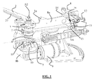
La
Selon le dispositif de lancement 1a montré à la
Le bras 2 est articulé autour d'un axe sensiblement vertical A2 en étant fixé à l'extrémité supérieure d'un arbre 3 supporté par une traverse 8a portée par le corps supérieur 8 du dispositif 1a, ledit arbre 3 étant libre en rotation par rapport à ce corps supérieur 8. Lors du lancer, le bras 2 tourne autour dudit axe A2 et subit une accélération angulaire qui plaque la cible contre la réglette 27, tout en faisant rouler celle-ci vers son extrémité. La cible est ensuite éjectée en tournant sur elle-même.The
Le bras 2 est indirectement solidaire par l'intermédiaire de l'arbre 3 d'une bielle 4 tournante autour de l'axe A2, une extrémité de la bielle 4 étant reliée à l'extrémité inférieure de l'arbre 3. La bielle 4 comprend à son autre extrémité opposée un téton 5 disposé sur la face de la bielle non orientée vers le bras 2 et faisant saillie vers le bas. Ce téton 5 de la bielle 4 est solidarisé à une extrémité d'un ressort de traction 6, l'autre extrémité du ressort de traction 6 étant solidarisée au corps supérieur 8 du dispositif 1 a. La bielle 4 est aussi reliée mécaniquement à une roue libre 7 montée sur l'arbre 3.The
Dans la partie inférieure du dispositif 1 a, un motoréducteur 9 est porté par le corps inférieur 8b du dispositif 1 a. Ce motoréducteur 9 entraîne en rotation, à travers ledit corps inférieur 8b, un maneton 10 dont l'axe de rotation est coaxial avec l'axe de rotation A2 de la bielle 4 et du bras 2. Sur le maneton 10, il est prévu un téton 11, faisant saillie au-dessus du maneton 10 et dont la trajectoire lors de la rotation du maneton 10 rencontre celle du téton 5 disposé à l'extrémité de la bielle 4, cette extrémité étant non adjacente à l'arbre 3. Les deux tétons 11 et 5 interfèrent entre eux, ceci avantageusement sur une hauteur d'environ 3 millimètres.In the lower part of the device 1a, a geared
Situé sensiblement au-dessus de la solidarisation du ressort 6 de traction sur le corps supérieur 8 du dispositif 1 a, il est prévu un contacteur 12 qui coïncide avec la trajectoire d'une portion du bras 2 quand celui-ci a tourné autour de son axe A2, cette portion étant avantageusement la portion d'extrémité du bras 2.Located substantially above the fastening of the
Dans un tel dispositif 1 a, le bras 2 est tournant autour du corps supérieur 8 et inférieur 8b du dispositif 1 a, la rotation du bras 2 s'effectuant avantageusement dans le sens trigonométrique avec la roue libre 7 interdisant toute rotation du bras 2 en sens contraire.In such a device 1a, the
Pour l'initiation du lancement d'une cible, un moyen de déclenchement à distance donne l'ordre au motoréducteur 9 de tourner. Pendant cette étape, dite étape d'armement, le maneton 10 tourne autour de l'axe coaxial avec l'axe de rotation A2 du bras 2 et le téton 11 se déplace jusqu'à venir en contact avec le téton 5 porté par la bielle 4, avantageusement en contact linéaire. La bielle 4, l'arbre 3 et le bras 2 sont alors entraînés en rotation jusqu'à la butée du bras 2 contre le contacteur 12. Idéalement, cet arrêt est le plus proche possible d'une position dite « point zéro ».For initiating the launch of a target, a remote triggering means instructs the geared
Au point zéro, le bras ne subit aucun couple d'où l'obtention d'un équilibre entre l'étape d'armement et l'étape de lancement.At the zero point, the arm undergoes no torque from which obtaining a balance between the arming step and the launching step.
En continuant la rotation du bras 2 dans le sens trigonométrique, le franchissement de ce point zéro génère un couple moteur sur le bras grâce au ressort 6 tendu, si aucun obstacle ne contre ce couple alors le ressort 6 de traction se détend soudainement et la libération du bras 2 entraine le lancement de la cible. Lors de l'étape de lancement par éjection de la cible hors du dispositif 1 a, le bras 2 effectue, sous l'action de détente du ressort 6 de traction, une rotation quasi-instantanée. Le bras 2 passe alors consécutivement par une position dite de repos à 180° du «point zéro » qu'il dépasse du fait de son inertie jusqu'à atteindre une position à 270° du « point zéro ». Cette position reste maintenue grâce à la roue libre 7 qui empêche toute rotation en sens contraire.By continuing the rotation of the
Dans le dispositif de l'art antérieur, le motoréducteur 9 est arrêté lorsque le bras 2 est au-delà du « point zéro » de sorte à s'assurer un déclenchement immédiat à l'ordre de lancement. Cette position est dénommée position de lancement. L'équilibre du système est alors un équilibre forcé et s'obtient en ajoutant un obstacle mobile sur la trajectoire du bras 2. Cet obstacle est constitué d'une gâchette 13 pivotante autour d'un axe 14. La gâchette 13 est maintenue en contact avec une tige d'électro-aimant 15 grâce à un ressort de rappel 16.In the device of the prior art, the geared
Lorsque l'électro-aimant 15 est alimenté, il fait pivoter la gâchette 13 qui libère ainsi le bras 2. Cela aboutit à un temps de réponse extrêmement faible, satisfaisant pour les applications de lancement quasi-instantané.When the
Cependant, cet arrangement présente de nombreux inconvénients. L'utilisation d'un électroaimant 15 augmente le prix du dispositif 1a et peut générer différents dysfonctionnements allant même jusqu'au blocage du dispositif 1 a. Ainsi, la commande électrique qui doit piloter l'électroaimant 15 avant le motoréducteur 9 peut faillir et/ou le noyau de l'électroaimant 15 peut rester coincer, ainsi que la gâchette 13, ce qui pose problème.However, this arrangement has many disadvantages. The use of an
Une conséquence possible est un blocage de la gâchette 13 en position ouverte, le bras 2 partant en rafale. Une intervention humaine est alors nécessaire pour ne pas lancer de cible inutilement.A possible consequence is a locking of the
Une autre conséquence possible est le blocage de la gâchette 13 en position fermée. Dans ce cas, le motoréducteur 9 pousse le bras 2 à écraser cette dernière. Une intervention humaine est nécessaire pour débloquer le mécanisme. Une fois l'obstacle libéré, le bras 2 produit son accélération en opérant une rotation rapide de 270°. Comme un ressort de traction 6 couramment utilisé nécessite entre 100 kg et 200 kg pour être étiré, l'énergie restituée durant sa détente est directement proportionnelle à sa raideur. Le danger pour le réparateur est alors réel et la plus grande prudence est requise lors de son intervention.Another possible consequence is the locking of the
On connaît en outre du document
Le but de la présente invention est de concevoir un dispositif de lancement de cible qui puisse présenter un temps de réponse quasi-instantané à un ordre de lancement tout en améliorant les problèmes de sécurité et de temps d'armement des dispositifs de l'état de la technique.The object of the present invention is to design a target launching device which can have a quasi-instantaneous response time to a launch order while improving the security and arming time problems of the devices of the state of the technique.
A cet effet, l'invention propose un dispositif de lancement de cible comprenant un bras de lancement mobile en rotation, des moyens de lancement et des moyens moteurs destinés à l'armement du bras par rotation dudit bras jusqu'à une position dite « point zéro », pour laquelle les moyens de lancement sont sous traction sans exercer de couple sur le bras caractérisé en ce qu'il comprend des moyens de blocage en butée du déplacement du bras , portés par les moyens moteurs et des moyens de blocage complémentaires portés par le bras, les moyens de blocage en butée et les moyens de blocage complémentaires étant configurés pour bloquer le bras au-delà du « point zéro » sur un secteur angulaire prédéfini suivant le sens de rotation du bras dans une position de lancement pour laquelle les moyens de lancement sous traction exercent un couple sur le bras et pour libérer le bras au- delà de la position de lancement pour laquelle les moyens de lancement se détendent afin d'effectuer la rotation du bras 2 pour le lancement de la cible.For this purpose, the invention proposes a target launch device comprising a launching arm rotatable, launching means and motor means for arming the arm by rotation of said arm to a position called "point zero ", for which the launching means are under tension without exerting torque on the arm, characterized in that it comprises means for blocking in abutment with the displacement of the arm, carried by the drive means and complementary locking means carried by the arm, the abutment locking means and the complementary locking means being configured to lock the arm beyond the "zero point" on a predefined angular sector in the direction of rotation of the arm in a launch position for which the means traction launch exert a torque on the arm and to release the arm beyond the launch position for which the launching means are relaxed in order to rotate
L'effet technique est un départ quasi-instantané de la cible lorsque les moyens moteurs dépassent sensiblement « le point zéro » et que les moyens de blocage cessent d'être opérationnels. La solution proposée par la présente invention présente l'avantage de proposer une étape d'armement courte avec un délai de lancement de la cible suivant l'ordre de lancement le plus court possible,The technical effect is a quasi-instantaneous departure of the target when the motor means substantially exceed the "zero point" and the locking means cease to be operational. The solution proposed by the present invention has the advantage of proposing a short arming step with a launch delay of the target in the shortest possible launch order,
De plus, ceci est obtenu avec des moyens de blocage portés par les moyens moteurs, ces moyens de blocage étant rendus inopérants lorsque les moyens moteurs sont remis en fonctionnement et que le bras avance en s'éloignant du « point zéro », ce qui assure une sécurité de fonctionnement du dispositif beaucoup plus élevée que le système à gâchette et à électro-aimant de l'état de la technique.In addition, this is obtained with locking means carried by the motor means, these locking means being rendered inoperative when the motor means are put back into operation and the arm moves away from the "zero point", which ensures a much higher operating safety of the device than the trigger system and electromagnet of the state of the art.
Dans le mode de réalisation où l'invention comporte un système de pignons, on peut déporter et différencier la rotation de l'axe et du bras de lancement et celle des moyens de blocage, en particulier de la butée. De ce fait, les moyens de blocage peuvent être, dans leur fonctionnement et positionnement, ajustés de sorte à éviter de ne pouvoir jouer que sur une faible gamme de positions relatives à des moyens de blocage du bras et de la butée. L'emploi d'une telle configuration à des fins de réglage du lancement est particulièrement avantageux.In the embodiment where the invention comprises a pinion system, it is possible to deport and differentiate the rotation of the axis and the throwing arm and that of the locking means, in particular the stop. Therefore, the locking means may be, in their operation and positioning, adjusted so as to avoid being able to play only on a small range of positions relative to means for locking the arm and the stop. The use of such a configuration for launch adjustment purposes is particularly advantageous.
De manière facultative, l'invention comprend en outre au moins l'une quelconque des caractéristiques suivantes :
- le bras de lancement comprend un arbre de rotation, ledit arbre portant un pignon entraîné par un second pignon entraînant relié à l'axe de sortie des moyens moteurs comprenant un motoréducteur, les moyens de blocage en butée comportant une butée portée à la périphérie d'un maneton tournant autour de l'axe de sortie du motoréducteur.
- le maneton est monté sur une roue libre, ladite roue libre autorisant la rotation du maneton dans le sens contraire de rotation du motoréducteur.
- la butée du maneton est portée par un axe excentré par rapport à l'axe de sortie du motoréducteur, ladite butée étant sous la forme d'un galet tournant à l'extrémité supérieure de l'axe excentré.
- les moyens de blocage complémentaires portés par le bras sont sous la forme d'un ergot entrant en contact avec la butée portée à la périphérie du maneton lors de la rotation du bras après le « point zéro ».
- l'entraînement entre les deux pignons est réalisé par une chaîne ou une courroie tournant autour desdits pignons.
- dans le pignon porté par l'arbre de rotation du bras est insérée une roue libre, la cage extérieure de la roue libre tournant dans le sens de rotation du bras.
- le dispositif comprend un corps fixe, lors de la rotation du bras, une butée solidarisée avec ledit corps étant en appui contre la tranche du maneton.
- la butée est pressée sous l'action d'un moyen élastique contre la tranche du maneton.
- les moyens de lancement sont sous la forme d'un ressort de traction apte à être tendu lors de la rotation du bras, le rappel en position détendue du ressort de traction effectuant la rotation du bras pour le lancement de la cible par le bras.
- le ressort de traction est fixé à une de ses extrémités au corps du dispositif, son autre extrémité étant articulée à une extrémité d'une bielle dont l'autre extrémité est reliée à l'arbre de rotation du bras.
- the throwing arm comprises a rotation shaft, said shaft carrying a pinion driven by a second driving pinion connected to the output shaft of the motor means comprising a geared motor, the stop blocking means comprising a stop carried on the periphery of a crankpin rotating around the output shaft of the geared motor.
- the crankpin is mounted on a free wheel, said free wheel allowing the rotation of the crankpin in the opposite direction of rotation of the geared motor.
- the stop of the crankpin is carried by an eccentric axis relative to the output shaft of the gearmotor, said stop being in the form of a roller rotating at the upper end of the eccentric axis.
- the complementary locking means carried by the arm are in the form of a lug coming into contact with the stop carried on the periphery of the crankpin during the rotation of the arm after the "zero point".
- the drive between the two gears is made by a chain or a belt rotating around said gears.
- in the pinion carried by the shaft rotation shaft is inserted a freewheel, the outer cage of the freewheel rotating in the direction of rotation of the arm.
- the device comprises a fixed body, during the rotation of the arm, an abutment secured to said body being in abutment against the edge of the crankpin.
- the stop is pressed under the action of an elastic means against the edge of the crankpin.
- the launching means are in the form of a tension spring capable of being tensioned during the rotation of the arm, the return in the relaxed position of the tension spring rotating the arm for launching the target by the arm.
- the tension spring is fixed at one of its ends to the body of the device, its other end being hinged to one end of a connecting rod whose other end is connected to the rotation shaft of the arm.
L'invention concerne aussi un procédé de lancement d'une cible par un dispositif de lancement tel que décrit précédemment, lequel procédé comprend les étapes successives suivantes :
- d'armement des moyens de lancement par rotation du bras entrainé par les moyens moteurs jusqu'au point zéro,
- d'entrainement du bras jusqu'à la position de lancement au-delà du point zéro suivant le sens de rotation du bras
- de blocage du bras dans la position de lancement, en gardant les moyens de lancement sous traction,
- de redémarrage des moyens moteurs, suite à un ordre de lancement de cible pour débloquer le bras, et lancement de la cible du bras par détente des moyens de lancement.
- arming means for launching by rotation of the arm driven by the motor means to the zero point,
- driving the arm to the launching position beyond the zero point in the direction of rotation of the arm
- locking the arm in the launching position, keeping the launching means under traction,
- restarting the motor means, following a target launch order to unlock the arm, and launching the target of the arm by triggering the launching means.
Selon une possibilité, l'arrêt des moyens moteurs est réalisé avant le blocage du bras dans la position de lancement.According to one possibility, the stopping of the motor means is achieved before the arm is locked in the launch position.
Avantageusement, le procédé comprend une étape de maintien en position du bras dans sa position finale de rotation après lancement, ladite position finale servant de position de départ pour l'étape d'armement d'un nouveau cycle de lancement.Advantageously, the method comprises a step of maintaining the position of the arm in its final rotational position after launching, said final position serving as the starting position for the arming step of a new launching cycle.
D'autres caractéristiques, buts et avantages de la présente invention apparaîtront à la lecture de la description détaillée qui va suivre et au regard des dessins annexés donnés à titre d'exemple non limitatif et sur lesquels :
- la
figure 1 est une représentation schématique d'un mode de réalisation connu de l'état de la technique, d'une vue en perspective d'un dispositif de lancement de cibles.
- the
figure 1 is a schematic representation of an embodiment known from the state of the art, a perspective view of a target launch device.
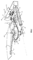
Les
- la
figure 2 est une représentation schématique d'une vue en perspective d'un dispositif de lancement de cibles selon la présente invention, ceci dans la position de repos, - la
figure 3 est une représentation schématique d'une vue en perspective d'un dispositif de lancement de cibles selon la présente invention, ceci dans la position après lancement à 270° du « point zéro », position qui peut aussi être la position de départ dans l'étape d'armement du dispositif, - la
figure 4 est une représentation schématique d'une vue en perspective d'un dispositif de lancement de cibles selon la présente invention, ceci dans une position de lancement ayant dépassé le point zéro et avec des moyens de blocage du bras en action, - la
figure 5 est une représentation schématique d'une vue en perspective d'un dispositif de lancement de cibles selon la présente invention, ceci dans une position de lancement, les moyens de blocage du bras n'étant plus actifs, cette position correspondant à un début de lancement de la cible, - la
figure 6 est une représentation schématique d'une vue en perspective d'un dispositif de lancement de cibles selon la présente invention, ceci dans une position en cours de lancement après celle de lafigure 5 , - la
figure 7 est une représentation schématique d'une vue en perspective d'un dispositif de lancement de cibles selon la présente invention, ceci dans une position de lancement postérieure à celle de lafigure 6 , cette position étant une position intermédiaire atteinte pendant le lancement de la cible.
- the
figure 2 is a schematic representation of a perspective view of a target launching device according to the present invention, this in the rest position, - the
figure 3 is a schematic representation of a perspective view of a target launching device according to the present invention, this in the position after launching at 270 ° of the "zero point", position which can also be the starting position in the step of arming the device, - the
figure 4 is a schematic representation of a perspective view of a target launching device according to the present invention, in a launch position having exceeded the zero point and with means for locking the arm in action, - the
figure 5 is a schematic representation of a perspective view of a target launch device according to the present invention, this in a launch position, the arm locking means no longer active, this position corresponding to a start of launching of the target, - the
figure 6 is a schematic representation of a perspective view of a target launch device according to the present invention, in a position being launched after that of thefigure 5 , - the
figure 7 is a schematic representation of a perspective view of a target launching device according to the present invention, in a launch position subsequent to that of thefigure 6 , this position being an intermediate position reached during the launch of the target.
Les
- la
figure 8 correspond à l'état du dispositif représenté à lafigure 2 : position de repos. - la
figure 9 correspond à l'état du dispositif représenté à lafigure 3 : position après le lancement à 270° du point zéro. - la
figure 10 correspond à un état du dispositif postérieur l'état représenté à lafigure 9 en étape d'armement. - la
figure 11 correspond à un état du dispositif postérieur à celui de lafigure 10 et situé entre celui représenté à lafigure 3 et celui de lafigure 4 : en position au point zéro. - la
figure 12 correspond à l'état du dispositif représenté à lafigure 4 : position de lancement. - la
figure 13 correspond à l'état du dispositif représenté à lafigure 5 : après position de lancement en cours de lancement de la cible.
- the
figure 8 corresponds to the state of the device represented infigure 2 : rest position. - the
figure 9 corresponds to the state of the device represented infigure 3 : position after launch at 270 ° from the zero point. - the
figure 10 corresponds to a state of the posterior device the state represented in thefigure 9 in arming step. - the
figure 11 corresponds to a state of the device posterior to that of thefigure 10 and located between the one shown in thefigure 3 and that of thefigure 4 : in position at the zero point. - the
figure 12 corresponds to the state of the device represented infigure 4 : launch position. - the
figure 13 corresponds to the state of the device represented infigure 5 : After launch position being launched from target.
Dans ce qui va suivre, il va être décrit un dispositif de lancement de cibles servant au tir sportif du type tir aux pigeons donc utilisant fréquemment des cibles en argile. Il convient de souligner que la présente invention n'est pas limitée par une telle utilisation et qu'elle peut concerner le lancement de cibles en mousse, par exemple destinées au tir à l'arc.In what follows, there will be described a device for launching targets for shooting sports like pigeon shooting so frequently using clay targets. It should be emphasized that the present invention is not limited by such use and may relate to the launching of foam targets, for example for archery purposes.
De même, le lancement de cibles peut se faire sensiblement en l'air avec une composante verticale importante ou sensiblement à ras de terre avec une composante horizontale importante.Similarly, the launching of targets can be done substantially in the air with a significant vertical component or substantially flush with a large horizontal component.
On entend par « porté » que les deux éléments sont solidaires cinématiquement. Toutes configurations respectant cette simultanéité cinématique rentrent dans l'objet de l'invention. Les deux éléments peuvent être directement ou indirectement reliés.The term "worn" means that the two elements are kinematically connected. All configurations respecting this kinematic simultaneity fall within the object of the invention. Both elements can be directly or indirectly related.
La
Le dispositif 1 de l'invention reprend certaines caractéristiques du dispositif de la
Les caractéristiques du bras 2 disposé à une extrémité d'un arbre 3 présentant une roue libre 7 tandis qu'à l'autre extrémité est disposée une bielle 4 restent sensiblement inchangées. La bielle 4 présente une extrémité reliée à l'arbre 3 tandis que son autre extrémité présente un pivot 5a d'articulation avec une extrémité du ressort 6 de traction, l'autre extrémité du ressort de traction 6 étant reliée au point 28 du corps supérieur 8 du dispositif 1 b.The characteristics of the
L'ensemble d'entraînement spécifique à ce mode de réalisation comprend un motoréducteur 9 entraînant un pignon d'entraînement 18 lui-même relié par une transmission du type chaîne 19 ou courroie à un pignon 17 porté par l'arbre 3. La roue libre 7 de l'arbre 3 coopère avec le pignon 17. Le motoréducteur 9 est disposé de manière que son axe de sortie A1 soit distant et parallèle à l'axe de rotation A2 du bras 2. A l'extrémité de sortie du motoréducteur 9 se trouve le pignon d'entraînement 18 de taille inférieure au pignon 17 et connecté à ce dernier à l'aide de la chaîne 19.The drive assembly specific to this embodiment comprises a geared
Situé au-dessus de l'extrémité du ressort de traction 6 reliée au corps supérieur 8, un contacteur 12 se trouve sur la trajectoire tournante du bras 2. Un dispositif de déclenchement à distance donne l'ordre au motoréducteur 9 de tourner, le pignon 18 entraînant le pignon 17 par l'intermédiaire de la chaîne 19. La cage extérieure de la roue libre 7 tournant dans le sens trigonométrique, la roue libre 7 devient solidaire de la bielle 4. Le système évolue jusqu'à l'interception du contacteur 12 par le bras 2.Located above the end of the
Lorsque le bras 2 et le pivot 5a passent au-delà du « point zéro », le ressort 6 de traction agit alors sur la bielle 4 dans le sens trigonométrique, ce qui aboutit à une accélération du bras 2. L'arrêt, dû à l'inertie du système, se produit à peu près à 270° du « point zéro ». Le maintien en cette position est possible du fait de la roue libre 7. Le motoréducteur 9 continuant de fonctionner, la roue libre 7 redevient motrice et entraîne de nouveau la bielle 4 pour une nouvelle étape d'armement.When the
Comme il est visible à la
Il est défini une position de repos du dispositif 1, dans laquelle l'axe X3 et l'axe X1 de la bielle 4 sont superposés l'un à l'autre. L'axe X1 est dans le prolongement de l'axe X2 ; la bielle 4 se trouvant dans l'alignement du ressort 6 de traction. Cette position est montrée aux
De même, il est défini une position dite « point zéro » du dispositif 1 illustrée en
Aux
Dans le procédé selon l'invention, l'étape d'armement du bras 2 du dispositif 1 peut commencer à partir d'une position de départ montrée aux
Pendant l'étape d'armement, le bras 2 effectue une rotation entraînée par le motoréducteur 9 jusqu'au « point zéro » dans le sens trigonométrique. Il est bien entendu possible de concevoir un dispositif avec un bras tournant dans l'autre sens. Le motoréducteur 9 entraîne par l'intermédiaire du pignon entraînant 18 le pignon 17 de l'arbre 3 de rotation du bras 2 et fait tourner ledit arbre 3 tandis que le ressort 6 de traction, illustrant les moyens de lancement du dispositif 1, se tend.During the arming step, the
Au « point zéro », la bielle 4 est encore en opposition contre la rétraction du ressort 6 de traction mais cesse de l'être passé ce « point zéro » en position de lancement. Ceci est montré aux
Selon une possibilité de la présente invention, le procédé de lancement prévoit une coupure du motoréducteur 9 dès que le « point zéro » a été franchi. La coupure du motoréducteur 9 peut être rendue possible par le contacteur 12 porté par le corps supérieur 8 du dispositif 1, ce contacteur 12 pouvant interrompre l'alimentation du motoréducteur 9 quand contacté par l'extrémité du bras 2. Le contacteur 12 est sensiblement positionné pour être en contact avec le bras 2 « au point zéro ». L'inertie du bras 2 l'entraîne au-delà du « point zéro » au point de lancement, alternativement le contacteur 12 peut différer l'arrêt du motoréducteur 9 pour amener le bras 2 en position de lancement. La coupure peut précéder ou être simultanée au blocage des moyens de lancement sous traction. Dans cette configuration, le dispositif 1 est en attente d'un ordre de lancement de cibleAccording to a possibility of the present invention, the launching method provides for a cut-off of the geared
Suite à un ordre de lancement de cible, donné par exemple par le tireur, il est effectué un redémarrage du motoréducteur 9 et le procédé selon l'invention comprend une étape d'entraînement du dispositif 1 par le motoréducteur 9, cette étape finissant par la libération des moyens de lancement sous traction de leur blocage.Following a target launch order, given for example by the shooter, the
Avantageusement, les moyens de blocage des moyens de lancement sous la forme du ressort 6 de traction sont des moyens opérant sur le bras 2 et présentent les caractéristiques suivantes en se référant aux
Sur l'arbre de sortie du motoréducteur 9 tournant autour de l'axe A1, au-dessus du pignon d'entraînement 18, il est prévu un maneton 21 avec une roue libre 20 en son intérieur. La roue libre 20 autorise la rotation du maneton 21 dans le sens horaire ou si ce dernier est bloqué, la rotation du motoréducteur 9 dans le sens trigonométrique. Le maneton 21 porte à sa périphérie un axe 22, l'axe 22 étant excentré par rapport à l'axe A1 du motoréducteur 9. Un galet 23, libre en rotation, est monté sur l'axe 22 en tournant donc autour d'un axe sensiblement vertical.On the output shaft of the geared
Un moyen élastique, sous la forme d'un ressort 24, relié à une de ses extrémités au corps supérieur 8 du dispositif 1 et à l'autre à la partie inférieure de l'axe 22, maintient la portion inférieure de l'axe 22 contre une butée 25. Sous une autre forme de réalisation, le ressort 24 peut presser la tranche du maneton 21 contre la butée 25.An elastic means, in the form of a
Vers l'extrémité libre du bras 2 de lancement et sur sa face inférieure, est fixé un ergot 26. Le galet 23 se trouve sur la trajectoire de l'ergot 26 lors de la rotation du 2 bras autour de l'axe A2. L'axe A2 du pignon 17 et de rotation du bras 2, l'axe A1 du pignon entraînant 18 et du motoréducteur 9 ainsi que l'axe 22 sont disposés dans cet ordre. Le contacteur 12 se trouve sur la trajectoire du bras 2.Toward the free end of the
Comme précédemment mentionné, dans le procédé de lancement selon la présente invention, à la fin de la phase d'armement du bras 2, le bras 2 atteint la position « point zéro » et la franchit. L'extrémité libre du bras 2 commute le contacteur 12 qui coupe l'alimentation du motoréducteur 9. Le « point zéro » ayant été franchi, la traction exercée par le ressort 6 de traction amène en contact l'ergot 26 du bras 2 avec le galet 23. Le motoréducteur 9 étant à l'arrêt, la roue libre 20 s'oppose au déplacement du maneton 21. Ceci est montré aux
Lorsque le motoréducteur 9 est de nouveau alimenté, après par exemple un ordre de lancement, il fait tourner la roue libre 20 et par conséquent le galet 23, ce qui libère le bras 2. Ceci est montré aux
Avantageusement, les dimensions des pignons 17 et 18 permettent de créer une réduction qui limite la pression de l'ergot 26 sur le galet 23.Advantageously, the dimensions of the
Le procédé de lancement selon l'invention comprend ainsi une étape de lancement par éjection de la cible du bras 2, ceci lors de la détente automatique des moyens de lancement formés par le ressort 6 de traction, aucun moyen de blocage ne les maintenant plus alors en position sous traction.The launching method according to the invention thus comprises a launching step by ejection of the target of the
Cette étape de lancement par éjection de la cible se poursuit consécutivement par les positions montrées aux
Conformément à l'invention, il n'y a aucun problème de synchronisation car seul le motoréducteur 9 est sollicité, le système de débrayage étant lié mécaniquement à ce dernier. La pression du bras 2 sur le galet 23 est ainsi totalement contrôlée et immuable. La commande électrique s'en trouve simplifiée et les risques de dysfonctionnements diminués. Seul un défaut lié au ressort de traction 6 pourrait aboutir à un départ en rafale du bras 2. La sécurité des personnes à proximité du dispositif 1 s'en trouve donc nettement améliorée, par rapport aux modes de réalisation de l'état de la technique montrés à la
Claims (10)
- Device (1) for launching targets comprising a rotatable launching arm (2), launching means (6) and motor means (9) intended to activate the arm (2) by rotating said arm (2) to a so-called "zero point" position, for which the launching means (6) are under traction without applying torque to the arm (2), the device (1) comprising means for locking (20 to 23) the arm (2) at a movement stop and additional locking means (26), the stop locking means (20-23) and the additional locking means (26) being configured to lock the arm (2) beyond the "zero point" on a predefined angular sector according to the direction of rotation of the arm (2) in a launching position for which the traction launching means apply a torque on the arm (2) and to release the arm (2) beyond the launching position for which the launching means are relaxed in order to perform the rotation of the arm (2) for launching the target, and wherein the launching arm (2) comprises a rotation shaft (3),
characterised in that
the means for locking the arm (2) in a movement stop are borne by the motor means (9), the additional locking means are borne by the arm (2),
said shaft (3) bears a pinion (17) driven by a second driving pinion (18) connected to the output shaft (A1) of the motor means comprising a geared motor (9) and the stop locking means (20 to 23) comprise a stop (23) borne at the periphery of a crank pin (21) rotating about the output shaft (A1) of the geared motor (9). - Device (1) according to the preceding claim, wherein the crank pin (21) is mounted on a free wheel (20), said free wheel (20) allowing the rotation of the crank pin (21) in the opposite direction of rotation of the geared motor (9).
- Device (1) according to any one of the preceding claims, wherein the stop (23) of the crank pin (21) is borne by an offset shaft (22) relative to the output shaft (A1) of the geared motor (9), said stop being in the form of a roller (23) rotating at the upper end of the offset shaft (22).
- Device (1) according to any one of the three preceding claims, wherein the additional locking means borne by the arm (2) are in the form of a tappet (26) coming into contact with the stop (23) borne at the periphery of the crank pin (21) during the rotation of the arm (2) after the "zero point".
- Device (1) according to any one of the preceding claims, wherein the drive between the two pinions (17, 18) is carried out by a chain (19) or a belt rotating around said pinions (17, 18).
- Device according to any one of the preceding claims, for which, in the pinion (17) borne by the rotation shaft (3) of the arm (2), is inserted a free wheel (7), the outer cage of the free wheel (7) rotating in the direction of rotation of the arm (2).
- Device (1) according to any one of the preceding claims, comprising a fixed body (8, 8a, 8b), a stop (25) rigidly connected to said body (8, 8a, 8b) bearing on the edge of the crank pin (21).
- Device (1) according to the preceding claim, for which the stop (25) is pressed under the action of elastic means (24) against the edge of the crank pin (21).
- Device (1) according to any one of the preceding claims, for which the launching means are in the form of a traction spring (6) suitable for being tightened during the rotation of the arm (2), the return to the relaxed position of the traction spring (6) rotating the arm (2) for the launch of the target by the arm (2).
- Device (1) according to the preceding claim, for which the traction spring (6) is secured at one of the ends thereof to the body (8) of the device (1), the other end thereof being hinged at one end with a connecting rod (4), the other end whereof is connected to the rotation shaft (3) of the arm (2).
Applications Claiming Priority (2)
| Application Number | Priority Date | Filing Date | Title |
|---|---|---|---|
| FR1256362A FR2993047B1 (en) | 2012-07-03 | 2012-07-03 | DEVICE FOR LAUNCHING TARGETS FOR INSTANT SPORTING SHOOTING OF THE TARGET |
| PCT/EP2013/063713 WO2014005952A1 (en) | 2012-07-03 | 2013-06-28 | Device for launching targets for sport shooting, with instantaneous take-off of the target |
Publications (2)
| Publication Number | Publication Date |
|---|---|
| EP2870427A1 EP2870427A1 (en) | 2015-05-13 |
| EP2870427B1 true EP2870427B1 (en) | 2016-08-10 |
Family
ID=47294941
Family Applications (1)
| Application Number | Title | Priority Date | Filing Date |
|---|---|---|---|
| EP13732193.1A Active EP2870427B1 (en) | 2012-07-03 | 2013-06-28 | Device for launching targets for sport shooting, with instantaneous take-off of the target |
Country Status (7)
| Country | Link |
|---|---|
| US (1) | US9605931B2 (en) |
| EP (1) | EP2870427B1 (en) |
| CN (1) | CN104395688B (en) |
| DK (1) | DK2870427T3 (en) |
| ES (1) | ES2602487T3 (en) |
| FR (1) | FR2993047B1 (en) |
| WO (1) | WO2014005952A1 (en) |
Families Citing this family (8)
| Publication number | Priority date | Publication date | Assignee | Title |
|---|---|---|---|---|
| FR3016208B1 (en) * | 2014-01-08 | 2016-02-05 | Laporte Holding | DEVICE FOR LAUNCHING TARGETS FOR INSTANT START SPORTS SHOOTING WITH ACTIVE LOCKING ARRANGEMENTS ON THE LAUNCHING ARM ROTATION TREE |
| FR3030714B1 (en) * | 2014-12-17 | 2017-01-13 | Laporte Holding | MACHINE FOR LAUNCHING TARGETS AND METHOD OF SETTING |
| DE102015212678A1 (en) * | 2015-07-07 | 2017-01-12 | Okm Gmbh | Method for operating a discarding system for flying discs |
| FR3048772B1 (en) | 2016-03-14 | 2018-09-28 | Laporte Holding | MACHINE FOR LAUNCHING AT LEAST ONE TARGET |
| US11617934B2 (en) | 2019-08-07 | 2023-04-04 | Robert M. SHIRLEY | Auto feed hockey puck passing mechanism |
| FR3100880B1 (en) * | 2019-09-13 | 2022-04-15 | Laporte Holding | Target throwing machine for clay pigeon shooting |
| FR3100879B1 (en) * | 2019-09-17 | 2022-04-15 | Laporte Holding | Target throwing device |
| US11441879B1 (en) | 2021-03-11 | 2022-09-13 | Bushnell Inc. | Trap machine with a spring manipulation mechanism |
Family Cites Families (9)
| Publication number | Priority date | Publication date | Assignee | Title |
|---|---|---|---|---|
| US1475713A (en) * | 1922-02-10 | 1923-11-27 | Charles H Napier | Motor-driven target-throwing machine |
| US2245258A (en) * | 1939-01-28 | 1941-06-10 | George H Darrell | Trap |
| US3097635A (en) * | 1961-03-02 | 1963-07-16 | Carl R Freeman | Target throwing apparatus |
| US3470860A (en) * | 1966-06-10 | 1969-10-07 | Remington Arms Co Inc | Target throwing trap |
| FR2093065A5 (en) * | 1970-06-01 | 1972-01-28 | Begeorges Michel | |
| FR2238136B1 (en) * | 1973-07-17 | 1976-06-18 | Laporte Sa | |
| SE9500155L (en) * | 1995-01-18 | 1996-07-19 | Beomat Ab | Clay Pigeon Throwers |
| FR2787181B1 (en) | 1998-12-15 | 2001-05-25 | Laporte Ball Trap | APPARATUS FOR LAUNCHING TARGETS OF THE CLAY TRAY TYPE |
| CN2656933Y (en) * | 2003-09-29 | 2004-11-17 | 吴文龙 | Automatic running fire target ejector |
-
2012
- 2012-07-03 FR FR1256362A patent/FR2993047B1/en not_active Expired - Fee Related
-
2013
- 2013-06-28 US US14/412,628 patent/US9605931B2/en active Active
- 2013-06-28 WO PCT/EP2013/063713 patent/WO2014005952A1/en active Application Filing
- 2013-06-28 EP EP13732193.1A patent/EP2870427B1/en active Active
- 2013-06-28 ES ES13732193.1T patent/ES2602487T3/en active Active
- 2013-06-28 CN CN201380034997.6A patent/CN104395688B/en not_active Expired - Fee Related
- 2013-06-28 DK DK13732193.1T patent/DK2870427T3/en active
Also Published As
| Publication number | Publication date |
|---|---|
| EP2870427A1 (en) | 2015-05-13 |
| US20150168108A1 (en) | 2015-06-18 |
| DK2870427T3 (en) | 2016-12-05 |
| US9605931B2 (en) | 2017-03-28 |
| FR2993047B1 (en) | 2015-04-10 |
| CN104395688A (en) | 2015-03-04 |
| WO2014005952A1 (en) | 2014-01-09 |
| FR2993047A1 (en) | 2014-01-10 |
| CN104395688B (en) | 2017-04-05 |
| ES2602487T3 (en) | 2017-02-21 |
Similar Documents
| Publication | Publication Date | Title |
|---|---|---|
| EP2870427B1 (en) | Device for launching targets for sport shooting, with instantaneous take-off of the target | |
| EP3092457B1 (en) | Target launching device for target shooting, with instantaneous take-off, with active blocking means on the rotational shaft of the launch arm | |
| WO2016096723A1 (en) | Manual launcher with remotely situated control | |
| EP2602804B1 (en) | Pole operating device in a medium-voltage electric control apparatus | |
| CA2725868C (en) | Simplified system for controlling propeller blade pitch in an aircraft turboshaft engine | |
| WO2011138342A1 (en) | Target launching device | |
| EP2062277B1 (en) | Device for controlling an electrical appliance | |
| EP2605256A1 (en) | Operating device of the motor-drive of the contact closing device reset device in an electric protection apparatus and apparatus comprising same | |
| EP3818327A1 (en) | Machine for launching targets with rotary barrel | |
| EP0744016B1 (en) | Fire interrupting and hangfire safety system for an automatic small- or medium-calibre multibarrel firearm | |
| EP3657522B1 (en) | Mechanism for controlling the opening and closing of a current interruption device for an electrical switch | |
| EP1067353B1 (en) | Firing device for ordnance by percussion of a fuse | |
| EP2575150A1 (en) | Motorization disengagement device of the reset device of the contact closing device in an electric protection apparatus and apparatus comprising same | |
| WO2017207917A1 (en) | Actuator for a clutch, notably for a motor vehicle | |
| EP3232459B1 (en) | Electric line protection apparatus | |
| EP4031477B1 (en) | Basket, notably aerial basket lifting device | |
| EP3902971B1 (en) | Rotation drive system for a rolling device for a roll-type closure | |
| FR2928723A1 (en) | Retarder device for additional range increasing equipment of air-ground guided bomb in aircraft, has activation unit activating rigid rod activated with preset delay relative to action of initial start during device's activation position | |
| WO2012028499A1 (en) | Device for launching targets to shoot at | |
| FR3037230A1 (en) | LOCKING DEVICE UNLOCKING A KNEE PROSTHESIS | |
| EP1500778A1 (en) | Shutter or sun protection Installation comprising a security device | |
| FR2460034A1 (en) | MANUAL AND MANUAL OPERATION CIRCUIT BREAKER | |
| FR2574534A1 (en) | Clay pigeon launcher | |
| FR3116503A1 (en) | Railway detector with mechanical timer | |
| BE399587A (en) |
Legal Events
| Date | Code | Title | Description |
|---|---|---|---|
| PUAI | Public reference made under article 153(3) epc to a published international application that has entered the european phase |
Free format text: ORIGINAL CODE: 0009012 |
|
| 17P | Request for examination filed |
Effective date: 20150202 |
|
| AK | Designated contracting states |
Kind code of ref document: A1 Designated state(s): AL AT BE BG CH CY CZ DE DK EE ES FI FR GB GR HR HU IE IS IT LI LT LU LV MC MK MT NL NO PL PT RO RS SE SI SK SM TR |
|
| AX | Request for extension of the european patent |
Extension state: BA ME |
|
| DAX | Request for extension of the european patent (deleted) | ||
| GRAP | Despatch of communication of intention to grant a patent |
Free format text: ORIGINAL CODE: EPIDOSNIGR1 |
|
| INTG | Intention to grant announced |
Effective date: 20160309 |
|
| GRAS | Grant fee paid |
Free format text: ORIGINAL CODE: EPIDOSNIGR3 |
|
| GRAA | (expected) grant |
Free format text: ORIGINAL CODE: 0009210 |
|
| AK | Designated contracting states |
Kind code of ref document: B1 Designated state(s): AL AT BE BG CH CY CZ DE DK EE ES FI FR GB GR HR HU IE IS IT LI LT LU LV MC MK MT NL NO PL PT RO RS SE SI SK SM TR |
|
| REG | Reference to a national code |
Ref country code: GB Ref legal event code: FG4D Free format text: NOT ENGLISH |
|
| REG | Reference to a national code |
Ref country code: CH Ref legal event code: EP Ref country code: AT Ref legal event code: REF Ref document number: 819457 Country of ref document: AT Kind code of ref document: T Effective date: 20160815 |
|
| REG | Reference to a national code |
Ref country code: IE Ref legal event code: FG4D Free format text: LANGUAGE OF EP DOCUMENT: FRENCH |
|
| REG | Reference to a national code |
Ref country code: DE Ref legal event code: R096 Ref document number: 602013010354 Country of ref document: DE |
|
| REG | Reference to a national code |
Ref country code: DK Ref legal event code: T3 Effective date: 20161128 |
|
| REG | Reference to a national code |
Ref country code: LT Ref legal event code: MG4D |
|
| REG | Reference to a national code |
Ref country code: NL Ref legal event code: MP Effective date: 20160810 |
|
| REG | Reference to a national code |
Ref country code: AT Ref legal event code: MK05 Ref document number: 819457 Country of ref document: AT Kind code of ref document: T Effective date: 20160810 |
|
| PG25 | Lapsed in a contracting state [announced via postgrant information from national office to epo] |
Ref country code: NL Free format text: LAPSE BECAUSE OF FAILURE TO SUBMIT A TRANSLATION OF THE DESCRIPTION OR TO PAY THE FEE WITHIN THE PRESCRIBED TIME-LIMIT Effective date: 20160810 Ref country code: NO Free format text: LAPSE BECAUSE OF FAILURE TO SUBMIT A TRANSLATION OF THE DESCRIPTION OR TO PAY THE FEE WITHIN THE PRESCRIBED TIME-LIMIT Effective date: 20161110 Ref country code: HR Free format text: LAPSE BECAUSE OF FAILURE TO SUBMIT A TRANSLATION OF THE DESCRIPTION OR TO PAY THE FEE WITHIN THE PRESCRIBED TIME-LIMIT Effective date: 20160810 Ref country code: RS Free format text: LAPSE BECAUSE OF FAILURE TO SUBMIT A TRANSLATION OF THE DESCRIPTION OR TO PAY THE FEE WITHIN THE PRESCRIBED TIME-LIMIT Effective date: 20160810 Ref country code: LT Free format text: LAPSE BECAUSE OF FAILURE TO SUBMIT A TRANSLATION OF THE DESCRIPTION OR TO PAY THE FEE WITHIN THE PRESCRIBED TIME-LIMIT Effective date: 20160810 Ref country code: IS Free format text: LAPSE BECAUSE OF FAILURE TO SUBMIT A TRANSLATION OF THE DESCRIPTION OR TO PAY THE FEE WITHIN THE PRESCRIBED TIME-LIMIT Effective date: 20161210 |
|
| REG | Reference to a national code |
Ref country code: ES Ref legal event code: FG2A Ref document number: 2602487 Country of ref document: ES Kind code of ref document: T3 Effective date: 20170221 |
|
| PG25 | Lapsed in a contracting state [announced via postgrant information from national office to epo] |
Ref country code: SE Free format text: LAPSE BECAUSE OF FAILURE TO SUBMIT A TRANSLATION OF THE DESCRIPTION OR TO PAY THE FEE WITHIN THE PRESCRIBED TIME-LIMIT Effective date: 20160810 Ref country code: LV Free format text: LAPSE BECAUSE OF FAILURE TO SUBMIT A TRANSLATION OF THE DESCRIPTION OR TO PAY THE FEE WITHIN THE PRESCRIBED TIME-LIMIT Effective date: 20160810 Ref country code: PT Free format text: LAPSE BECAUSE OF FAILURE TO SUBMIT A TRANSLATION OF THE DESCRIPTION OR TO PAY THE FEE WITHIN THE PRESCRIBED TIME-LIMIT Effective date: 20161212 Ref country code: AT Free format text: LAPSE BECAUSE OF FAILURE TO SUBMIT A TRANSLATION OF THE DESCRIPTION OR TO PAY THE FEE WITHIN THE PRESCRIBED TIME-LIMIT Effective date: 20160810 Ref country code: PL Free format text: LAPSE BECAUSE OF FAILURE TO SUBMIT A TRANSLATION OF THE DESCRIPTION OR TO PAY THE FEE WITHIN THE PRESCRIBED TIME-LIMIT Effective date: 20160810 Ref country code: GR Free format text: LAPSE BECAUSE OF FAILURE TO SUBMIT A TRANSLATION OF THE DESCRIPTION OR TO PAY THE FEE WITHIN THE PRESCRIBED TIME-LIMIT Effective date: 20161111 |
|
| PG25 | Lapsed in a contracting state [announced via postgrant information from national office to epo] |
Ref country code: RO Free format text: LAPSE BECAUSE OF FAILURE TO SUBMIT A TRANSLATION OF THE DESCRIPTION OR TO PAY THE FEE WITHIN THE PRESCRIBED TIME-LIMIT Effective date: 20160810 Ref country code: EE Free format text: LAPSE BECAUSE OF FAILURE TO SUBMIT A TRANSLATION OF THE DESCRIPTION OR TO PAY THE FEE WITHIN THE PRESCRIBED TIME-LIMIT Effective date: 20160810 |
|
| REG | Reference to a national code |
Ref country code: DE Ref legal event code: R097 Ref document number: 602013010354 Country of ref document: DE |
|
| PG25 | Lapsed in a contracting state [announced via postgrant information from national office to epo] |
Ref country code: BG Free format text: LAPSE BECAUSE OF FAILURE TO SUBMIT A TRANSLATION OF THE DESCRIPTION OR TO PAY THE FEE WITHIN THE PRESCRIBED TIME-LIMIT Effective date: 20161110 Ref country code: SK Free format text: LAPSE BECAUSE OF FAILURE TO SUBMIT A TRANSLATION OF THE DESCRIPTION OR TO PAY THE FEE WITHIN THE PRESCRIBED TIME-LIMIT Effective date: 20160810 Ref country code: SM Free format text: LAPSE BECAUSE OF FAILURE TO SUBMIT A TRANSLATION OF THE DESCRIPTION OR TO PAY THE FEE WITHIN THE PRESCRIBED TIME-LIMIT Effective date: 20160810 Ref country code: CZ Free format text: LAPSE BECAUSE OF FAILURE TO SUBMIT A TRANSLATION OF THE DESCRIPTION OR TO PAY THE FEE WITHIN THE PRESCRIBED TIME-LIMIT Effective date: 20160810 |
|
| PLBE | No opposition filed within time limit |
Free format text: ORIGINAL CODE: 0009261 |
|
| STAA | Information on the status of an ep patent application or granted ep patent |
Free format text: STATUS: NO OPPOSITION FILED WITHIN TIME LIMIT |
|
| REG | Reference to a national code |
Ref country code: FR Ref legal event code: PLFP Year of fee payment: 5 |
|
| 26N | No opposition filed |
Effective date: 20170511 |
|
| PG25 | Lapsed in a contracting state [announced via postgrant information from national office to epo] |
Ref country code: SI Free format text: LAPSE BECAUSE OF FAILURE TO SUBMIT A TRANSLATION OF THE DESCRIPTION OR TO PAY THE FEE WITHIN THE PRESCRIBED TIME-LIMIT Effective date: 20160810 |
|
| PG25 | Lapsed in a contracting state [announced via postgrant information from national office to epo] |
Ref country code: MC Free format text: LAPSE BECAUSE OF FAILURE TO SUBMIT A TRANSLATION OF THE DESCRIPTION OR TO PAY THE FEE WITHIN THE PRESCRIBED TIME-LIMIT Effective date: 20160810 |
|
| REG | Reference to a national code |
Ref country code: CH Ref legal event code: PL |
|
| REG | Reference to a national code |
Ref country code: IE Ref legal event code: MM4A |
|
| PG25 | Lapsed in a contracting state [announced via postgrant information from national office to epo] |
Ref country code: LU Free format text: LAPSE BECAUSE OF NON-PAYMENT OF DUE FEES Effective date: 20170628 Ref country code: IE Free format text: LAPSE BECAUSE OF NON-PAYMENT OF DUE FEES Effective date: 20170628 Ref country code: CH Free format text: LAPSE BECAUSE OF NON-PAYMENT OF DUE FEES Effective date: 20170630 Ref country code: LI Free format text: LAPSE BECAUSE OF NON-PAYMENT OF DUE FEES Effective date: 20170630 |
|
| REG | Reference to a national code |
Ref country code: BE Ref legal event code: MM Effective date: 20170630 |
|
| REG | Reference to a national code |
Ref country code: FR Ref legal event code: PLFP Year of fee payment: 6 |
|
| PG25 | Lapsed in a contracting state [announced via postgrant information from national office to epo] |
Ref country code: BE Free format text: LAPSE BECAUSE OF NON-PAYMENT OF DUE FEES Effective date: 20170630 |
|
| PG25 | Lapsed in a contracting state [announced via postgrant information from national office to epo] |
Ref country code: MT Free format text: LAPSE BECAUSE OF FAILURE TO SUBMIT A TRANSLATION OF THE DESCRIPTION OR TO PAY THE FEE WITHIN THE PRESCRIBED TIME-LIMIT Effective date: 20160810 |
|
| PG25 | Lapsed in a contracting state [announced via postgrant information from national office to epo] |
Ref country code: AL Free format text: LAPSE BECAUSE OF FAILURE TO SUBMIT A TRANSLATION OF THE DESCRIPTION OR TO PAY THE FEE WITHIN THE PRESCRIBED TIME-LIMIT Effective date: 20160810 |
|
| PG25 | Lapsed in a contracting state [announced via postgrant information from national office to epo] |
Ref country code: HU Free format text: LAPSE BECAUSE OF FAILURE TO SUBMIT A TRANSLATION OF THE DESCRIPTION OR TO PAY THE FEE WITHIN THE PRESCRIBED TIME-LIMIT; INVALID AB INITIO Effective date: 20130628 |
|
| PGFP | Annual fee paid to national office [announced via postgrant information from national office to epo] |
Ref country code: BE Payment date: 20190418 Year of fee payment: 5 Ref country code: FI Payment date: 20190520 Year of fee payment: 7 |
|
| PG25 | Lapsed in a contracting state [announced via postgrant information from national office to epo] |
Ref country code: CY Free format text: LAPSE BECAUSE OF FAILURE TO SUBMIT A TRANSLATION OF THE DESCRIPTION OR TO PAY THE FEE WITHIN THE PRESCRIBED TIME-LIMIT Effective date: 20160810 |
|
| PGFP | Annual fee paid to national office [announced via postgrant information from national office to epo] |
Ref country code: ES Payment date: 20190701 Year of fee payment: 7 |
|
| PG25 | Lapsed in a contracting state [announced via postgrant information from national office to epo] |
Ref country code: MK Free format text: LAPSE BECAUSE OF FAILURE TO SUBMIT A TRANSLATION OF THE DESCRIPTION OR TO PAY THE FEE WITHIN THE PRESCRIBED TIME-LIMIT Effective date: 20160810 |
|
| PG25 | Lapsed in a contracting state [announced via postgrant information from national office to epo] |
Ref country code: TR Free format text: LAPSE BECAUSE OF FAILURE TO SUBMIT A TRANSLATION OF THE DESCRIPTION OR TO PAY THE FEE WITHIN THE PRESCRIBED TIME-LIMIT Effective date: 20160810 |
|
| REG | Reference to a national code |
Ref country code: FI Ref legal event code: MAE |
|
| REG | Reference to a national code |
Ref country code: DK Ref legal event code: EBP Effective date: 20200630 |
|
| PG25 | Lapsed in a contracting state [announced via postgrant information from national office to epo] |
Ref country code: FI Free format text: LAPSE BECAUSE OF NON-PAYMENT OF DUE FEES Effective date: 20200628 |
|
| PGFP | Annual fee paid to national office [announced via postgrant information from national office to epo] |
Ref country code: DE Payment date: 20210616 Year of fee payment: 9 Ref country code: IT Payment date: 20210610 Year of fee payment: 9 |
|
| PG25 | Lapsed in a contracting state [announced via postgrant information from national office to epo] |
Ref country code: DK Free format text: LAPSE BECAUSE OF NON-PAYMENT OF DUE FEES Effective date: 20200630 |
|
| REG | Reference to a national code |
Ref country code: ES Ref legal event code: FD2A Effective date: 20211105 |
|
| PG25 | Lapsed in a contracting state [announced via postgrant information from national office to epo] |
Ref country code: ES Free format text: LAPSE BECAUSE OF NON-PAYMENT OF DUE FEES Effective date: 20200629 |
|
| REG | Reference to a national code |
Ref country code: DE Ref legal event code: R119 Ref document number: 602013010354 Country of ref document: DE |
|
| PG25 | Lapsed in a contracting state [announced via postgrant information from national office to epo] |
Ref country code: DE Free format text: LAPSE BECAUSE OF NON-PAYMENT OF DUE FEES Effective date: 20230103 |
|
| PG25 | Lapsed in a contracting state [announced via postgrant information from national office to epo] |
Ref country code: IT Free format text: LAPSE BECAUSE OF NON-PAYMENT OF DUE FEES Effective date: 20220628 |
|
| PGFP | Annual fee paid to national office [announced via postgrant information from national office to epo] |
Ref country code: FR Payment date: 20230629 Year of fee payment: 11 |
|
| PGFP | Annual fee paid to national office [announced via postgrant information from national office to epo] |
Ref country code: GB Payment date: 20230620 Year of fee payment: 11 |
|
| P01 | Opt-out of the competence of the unified patent court (upc) registered |
Effective date: 20240318 |