EP4031477B1 - Basket, notably aerial basket lifting device - Google Patents
Basket, notably aerial basket lifting device Download PDFInfo
- Publication number
- EP4031477B1 EP4031477B1 EP20772365.1A EP20772365A EP4031477B1 EP 4031477 B1 EP4031477 B1 EP 4031477B1 EP 20772365 A EP20772365 A EP 20772365A EP 4031477 B1 EP4031477 B1 EP 4031477B1
- Authority
- EP
- European Patent Office
- Prior art keywords
- link
- rotary
- platform
- basket
- deformation
- Prior art date
- Legal status (The legal status is an assumption and is not a legal conclusion. Google has not performed a legal analysis and makes no representation as to the accuracy of the status listed.)
- Active
Links
- 238000004804 winding Methods 0.000 claims description 95
- 238000001514 detection method Methods 0.000 claims description 21
- 230000000694 effects Effects 0.000 claims description 14
- 238000006073 displacement reaction Methods 0.000 description 17
- 230000002779 inactivation Effects 0.000 description 4
- 230000001965 increasing effect Effects 0.000 description 4
- 238000012423 maintenance Methods 0.000 description 3
- 241000287107 Passer Species 0.000 description 2
- 238000004590 computer program Methods 0.000 description 2
- 230000000007 visual effect Effects 0.000 description 2
- 102100033121 Transcription factor 21 Human genes 0.000 description 1
- 101710119687 Transcription factor 21 Proteins 0.000 description 1
- 208000027418 Wounds and injury Diseases 0.000 description 1
- 230000004913 activation Effects 0.000 description 1
- 238000012550 audit Methods 0.000 description 1
- 239000000470 constituent Substances 0.000 description 1
- 230000006378 damage Effects 0.000 description 1
- 238000013500 data storage Methods 0.000 description 1
- 230000009977 dual effect Effects 0.000 description 1
- 230000003028 elevating effect Effects 0.000 description 1
- 230000001939 inductive effect Effects 0.000 description 1
- 208000014674 injury Diseases 0.000 description 1
- 210000000056 organ Anatomy 0.000 description 1
- 230000035484 reaction time Effects 0.000 description 1
- 230000004043 responsiveness Effects 0.000 description 1
- 230000035945 sensitivity Effects 0.000 description 1
- 230000007704 transition Effects 0.000 description 1
Images


Classifications
-
- B—PERFORMING OPERATIONS; TRANSPORTING
- B66—HOISTING; LIFTING; HAULING
- B66F—HOISTING, LIFTING, HAULING OR PUSHING, NOT OTHERWISE PROVIDED FOR, e.g. DEVICES WHICH APPLY A LIFTING OR PUSHING FORCE DIRECTLY TO THE SURFACE OF A LOAD
- B66F17/00—Safety devices, e.g. for limiting or indicating lifting force
- B66F17/006—Safety devices, e.g. for limiting or indicating lifting force for working platforms
-
- B—PERFORMING OPERATIONS; TRANSPORTING
- B66—HOISTING; LIFTING; HAULING
- B66F—HOISTING, LIFTING, HAULING OR PUSHING, NOT OTHERWISE PROVIDED FOR, e.g. DEVICES WHICH APPLY A LIFTING OR PUSHING FORCE DIRECTLY TO THE SURFACE OF A LOAD
- B66F11/00—Lifting devices specially adapted for particular uses not otherwise provided for
- B66F11/04—Lifting devices specially adapted for particular uses not otherwise provided for for movable platforms or cabins, e.g. on vehicles, permitting workmen to place themselves in any desired position for carrying out required operations
- B66F11/044—Working platforms suspended from booms
Definitions
- the present invention relates to a nacelle, in particular a lifting platform.
- the nacelles in particular elevating ones, are well known to those skilled in this art as illustrated by the patent FR 2,909,084 .
- a nacelle there is a risk of injury to the operator placed on the platform when the latter, while controlling the platform movement drive system, hits the back of the head or the back of the platform. back, an obstacle, such as a beam, which tends to drag the operator towards the control console, the latter then finding himself sandwiched between the obstacle and the control console with a risk of crushing against the console control.
- This problem is perfectly known and solutions using a cable or a bar security have already been imagined to solve this problem as illustrated for example by patents EP 2 794 461 Or EP 2 096 078 which discloses the preamble to claim 1.
- a cable or bar positioned in front of the control console allows, in the state requested by the operator, to control the stopping of the drive in movement of the platform generally by inactivation of the controls of the control system. driving movement of the platform.
- the cable or the bar can be stressed, for example, when the operator positioned standing in front of the control console is forced to lean towards the control console until exerting pressure on the cable.
- such solutions present a risk of getting stuck between the cable or safety bar and the obstacle, once the movement of the platform has stopped.
- An aim of the invention is to propose a nacelle whose design makes it possible to limit the risk of the operator being trapped between the flexible safety link and the obstacle once the movement of the platform has stopped without harming the compactness of the systems. maintaining the link.
- the or at least one of the members for detecting a deformation of the link is a member for detecting the angular position of the rotating member for winding the link of one support systems. It is thus possible to increase the travel of the link without increasing the reaction time of the detection member. It can in fact be allowed for the detection member to pass from the inactive state to the active state from the start of an angular movement of the rotary winding member of the link resulting from a deformation of the link and as a result of stopping any movement of the platform while allowing the rotary winding member of the link to continue its angular displacement stroke in the direction of unwinding of the link of the rotary winding member, including at the active state of the detection organ.
- the platform stop command can for example be carried out at the start or in the middle of the angular displacement range of the rotary winding member of the link resulting from the deformation of the link by pressure exerted on the link without harming the continuation of the angular movement of the rotating member for winding the link in the direction of unwinding of the link.
- the nacelle comprises a control unit with which the device for detecting a deformation of the link is configured to communicate, this control unit being configured to emit a control signal for stopping the operation of the controls of the platform movement drive system based on the data received from the detection device.
- the or at least one of the members for detecting a deformation of the link is a sensor for detecting the angular position of the rotating member for winding the link of one maintenance systems by contact with said rotary member for winding the link or without contact, this sensor being electrically connected to the control unit and being configured to send to the control unit an electrical signal depending at least on the angular position of the rotating member for winding the link of said holding system.
- this design of the member for detecting a deformation of the link makes it possible to act on the movement of the platform as soon as an angular movement of the rotating member for winding the link is detected without harming the continuation of the angular movement of the rotary winding member of the link in the direction of unwinding of the link of said rotary winding member so that the risk of the operator being trapped between the flexible safety link and an obstacle, an once the movement of the platform has stopped, is reduced due to the remaining travel allowing the link to be released.
- the nacelle comprises a system for resetting the operation of the command(s) of the platform movement drive system, in the state prevented from operating the commands, this system comprising a member manually actionable reset button.
- the reset member is configured to, in the actuated state, control the drive system to move the platform in a predefined manner to allow the operator to disengage.
- the rotary member for winding the link of one of the holding systems is a pulley wheel carried by an axle disposed in a stationary manner on the platform, said pulley wheel having a rim configured to receive the link coupled by one of its ends to the wheel and the elastic return member of said rotating winding member is a spring, preferably torsion spring.
- the elastic return member of said rotating winding member is therefore configured to exert on the wheel a driving force in rotation of the wheel in the direction of winding of the link around the wheel. Pulling on the link in the direction of unwinding of the wheel link therefore makes it possible to move the wheel to which the link is coupled against the return action of the spring on the wheel.
- the nacelle comprises a stop for limiting the angular movement of the rotary winding member of the link of one of the holding systems, said stop being configured to limit the angular movement of the rotary member beyond a predetermined displacement stroke on the one hand, in the driven state of the rotating member in the clockwise direction, on the other hand, in the driven state of the rotating member in the anticlockwise.
- the dual function of the angular stop makes it possible to limit the angular displacement of the rotary winding member of the link in all situations of deformation of the link, this deformation possibly resulting from tension of the link for example by pressure exerted on the link by the operator or a loosening of the link for example in the case of a break in the link.
- the nacelle comprising a stop for limiting the angular movement of the rotary winding member of the link of one of the holding systems, said stop being configured to limit the angular movement of the rotary member at least in the direction of unwinding of the link of said rotating member beyond a predetermined angular displacement stroke of said rotating member, the member for detecting a deformation of the link is configured to, under the effect of a deformation of the link, moving from an inactive state to an active state in an angular position of said rotary link winding member other than the or at least one of the angular positions of said rotary link winding member corresponding to an end position of said rotating winding member materialized by said stop.
- each of the holding systems comprising a rotating member for winding the link around which the link partially winds, and an elastic return member formed by a spring equipping said rotating member
- the device for detecting a deformation of the link comprising a member for detecting a deformation of the link formed by a member for detecting the angular position of the rotating member for winding the link of only one of the holding systems said system main holding system
- the stiffness of the spring fitted to this main holding system is less than the stiffness of the spring fitted to the other holding system. This results in increased sensitivity of the holding systems.
- the nacelle is a lifting platform.
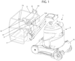
- the subject of the invention is a nacelle 1 which comprises a platform 7 having a location 71 for receiving an operator 30.
- This work platform 7 is here formed of a floor and guardrails surrounding the floor while allowing access to the interior of said platform.
- the operator 30 is generally standing inside the location 71 for receiving the platform 7 and faces a control console 3 carried by the platform 7.
- This control console 3 is generally arranged at a distance from the floor of platform 7 along the guardrail of platform 7 as illustrated in figure 1 .
- This control console 3 is equipped with at least one, preferably several, manually operable controls 4 such as buttons, levers, or others. These commands 4 allow the control of a system 2 for driving the movement of the platform 7.
- This system 2 for driving the movement of the platform 7 can affect a large number of shapes depending on the type of nacelle which can be a suspended nacelle or carried by a mobile chassis as in the example shown in the figure 1 .
- the system 2 for driving the movement of the platform 7 may include a winch on board said nacelle and cables for suspending the nacelle using the winch.
- Platform 7 can still be driven in elevation relative to the carrier chassis 16, as in the example shown in figure 1 , to form a lifting pod 1.
- Chassis 16 is therefore a motorized chassis equipped with wheels or tracks.
- the platform 7 is connected to the chassis 16 by an elevation structure comprising at least one actuator of the elevation structure.
- Actuator and elevation structure form part of the system 2 for driving the movement of the platform 7.
- the elevation structure here comprises at least one arm pivoting around a horizontal axis and the actuator is a cylinder. actuation of said arm extending between the arm and the chassis 16. This arm is preferably a telescopic arm.
- the controls 4 of the control console 3 allow the control of the system 2 for driving movement of the platform 7 by actuation of the motor of the chassis 16 and/or at least one actuator of the elevation structure to allow movement of the platform 7 by movement on the ground of the chassis 16 and/or by movement of the arm.
- This system 2 for driving the movement of the platform 7 will not be described in more detail because it is well known to those skilled in this art.
- the nacelle 1 also includes a flexible safety link 5 which can be made in the form of a cable, a belt, a chain or other.
- the flexible security link 5 is a cable.
- This link 5 has two ends shown at 51 in the figures.
- the nacelle 1 also includes two systems 6 for maintaining the link 5 carried by the platform 7. These systems 6 for maintaining the link are arranged facing each other. These holding systems 6 are here carried by two guardrails each delimiting a vertical side of the floor of the platform 7, said sides being opposite.
- the systems 6 for maintaining the link 5 are arranged, one, at one of the ends, the other, at the other end of the link 5 for maintaining the link 5 in at least one position in which the link 5 extends in the stretched state horizontally or substantially horizontally, that is to say ⁇ 20°.
- the link 5 thus extends substantially parallel to within ⁇ 20° to the support plane of the floor of the platform 7.
- the link 5 extends across the platform 7 by connecting, for example as in the examples shown, two sides opposite verticals of the platform adjoining the floor of the platform.
- this link 5 extends across the platform 7 near the control console 3 on the trajectory that can be followed by a part of the body, in particular the upper part of the body of an operator standing in front of the console 3 of command and leaning towards the control console 3.
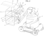
- This link 5 thus forms a demarcation line between part of the location 71 for receiving the operator of the platform 7 and the control console 3 to be able to be requested by the operator as soon as the latter is unbalanced towards the forward, for example under the effect of a push from the back by an obstacle as illustrated in figure 2 .
- link 5 under the effect of pressure exerted by the operator on link 5 causes an increase in the volume of location 71 that can be occupied by the operator on platform 7.
- the link maintenance systems 6 may be identical or different from one maintenance system to another.
- At least one of the holding systems 6 comprises a rotary member 10 for winding the link 5 around which the link 5 coupled to said rotary member 10 partially winds.
- Said rotary member 10 is equipped with at least one elastic return member 11 of said rotary member 10 configured to exert on said rotary member 10 a driving force in angular displacement of the rotary member 10 in the direction of winding of the link 5 around said rotary member 10.
- each holding system 6 comprises a rotating member 10 for winding the link and a member 11 for elastic return of the rotating member 10 for winding the link, these elements each being housed in a fixed housing to the platform.
- the rotating member 10 for winding the link is, preferably, as in the examples shown, a pulley wheel 101 carried by an axis 102 disposed in a stationary manner on the platform.
- the pulley wheel 101 and its axis 102 are housed at least partially inside the housing carried by the platform 7 when the latter is present.
- the wheel 101 rotates around the axis 102.
- This wheel 101 has a rim 103 providing, for example, a groove to receive the part of the link 5 winding around the wheel 101.
- the end 51 of the link is coupled to wheel 101.
- the end 51 of link 5 can be equipped with a cable stop fitting into a housing of wheel 101.
- the elastic return member 11 of the rotary winding member 10 is, for its part, an elastically deformable member which can assume a large number of shapes.
- This return member 11 is produced here in the form of a torsion spring which winds at least partially around the stationary axis 102 of rotation of the wheel 101.
- This spring is a hairpin spring with two branches connected by a spiral winding wrapping around the axis. One of the branches of the spring rests on a fixed stop external to the wheel 101 while the other branch of the spring is coupled to the pulley wheel 101.
- the branches are elastically returned to a spaced position from one another.
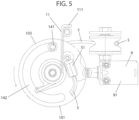
- the nacelle 1 comprises a stop 14 for limiting the angular movement of the rotary winding member 10 of the link 5.
- This stop 14 here affects the shape of a stud 141 circulating in a circular guide path 142 provided on the rotary winding member 10 of the link 5 and with a center radius passing through the axis of rotation of the rotary winding member 10 of the link 5
- This guide path 142 has, in the examples shown, the shape of an elongated curved groove closed at each of its ends and inside which the stud 141 is arranged in the unstressed state of the link 5. extending in the stretched state between the holding systems 6.
- the stud 141 extends in the guide path 142 between the ends of the guide path 142.
- an angular movement of the wheel 101 relative to the stud 141 up to a position in which the stud 141 bears against one end of the guide path 142 provided on the wheel 101 can take place in both directions of movement. driving movement of the wheel 101.
- the stop 14 is therefore configured to limit the angular displacement of the rotary member 10 beyond a predetermined displacement stroke, on the one hand, in the driven state of the rotary member 10 in the clockwise direction, on the other hand, to the driven state of the member 10 rotating in the counterclockwise direction.
- the stop 14 acts as an end stop during deformation of the link by pressure exerted on the link 5 or by release of the link 5 when, for example, the link 5 is broken.
- figures 4 And 5 there Figure 3 illustrating the position of the stud 141 forming the stop 14 in the unloaded state of the link 5.
- the nacelle 1 also comprises a device 8 for detecting a deformation of the link 5.
- This detection device 8 comprises at least one member 9 for detecting a deformation of the link 5.
- This detection member 9 is configured to, under the effect of a deformation of the link 5, to move from a so-called inactive state in which the operation of the command(s) 4 of the system 2 for driving the movement of the platform 7 is not prevented, that is to say -say the manual actuation by the operator of the command(s) 4, allows control of the system 2 for driving movement of the platform to a so-called active state in which the operation of the command(s) 4 is prevented, c that is to say, the manual actuation of the command(s) 4 by the operator has no effect on the control of the system 2 for driving the movement of the platform 7 so that the platform 7 is stopped.
- connection between the detection member 9 and the controls 4 to allow inactivation of the controls 4 in the active state of the detection member 9 can affect a large number of shapes.
- the nacelle includes an emergency stop button 15 fitted to the control console.
- This emergency stop button 15 in the state activated by the operator prevents any power supply in particular to the controls 4 of the control console so that their actuation by the operator has no effect on the movement drive system of platform 7.
- the member 9 for detecting a deformation of the link 5 can behave like an emergency stop button and invalidate the command(s) 4 in a manner similar to what can be provided in terms of inactivation of the command(s) in the case of actuation of the emergency stop button 15.
- the nacelle 1 comprises an electrical circuit for supplying the controls 4 of the control console and the member 9 for detecting a deformation of the link 5 is configured to open/close said electrical circuit as a function of the angular position of the rotating member 10 for winding the link, said controls 4 being inactive in the open state of the circuit.
- the member 9 for detecting a deformation of the link is configured to pass from the inactive state in which it closes the circuit to the active state in which it opens the circuit under the effect of a deformation of the link 5.
- the nacelle 1 comprises a control unit 12 with which the device 8 for detecting a deformation of the link 5 is configured to communicate.
- This control unit 12 is configured to emit a control signal to stop the operation of the controls 4 of the system 2 for driving the movement of the platform 7 as a function of the data received from the detection device 8.
- the nacelle 1 can include a sound and/or light warning device and the control unit 12 can also be configured to emit a warning signal, that is to say a warning signal. visual and/or audible alert depending on the data received from the device 8 for detecting a deformation of the link 5 in a manner known in itself.
- the control unit 12 is an electrical and/or computer system. Said control unit comprises, for example, a processor or controller, or dedicated electronic components or FPGA type components or ASIC. It is also possible to combine computer parts and electronic parts.
- the control unit 12 can be at least partially common with a nacelle computer associated with the control console.
- control unit 12 can be implemented in the form of a computer program or via hardware components (for example programmable gate networks) implemented in, and/or forming part of said unit 12 control.
- Computer programs or computer instructions may be contained in program storage devices, for example computer-readable digital data storage media or executable programs. Programs or instructions can also be executed from program storage devices.
- the member 9 for detecting a deformation of the link 5 is a member for detecting the angular position of the rotating member 10 for winding the link 5 of one of the holding systems 6.
- This member 9 for detecting the angular position of the rotating member 10 for winding the link 5 can affect a large number of shapes.
- This member 9 for detecting the angular position of the rotary member 10 for winding the link 5 can be a sensor 91 for detecting the angular position of the member 10 for winding the link 5 by contact with said rotary member 10 winding of the link 5 as in the example shown where the sensor is of the push-button type with a movable part.
- the mobile part of this sensor is, in the inactive state of the sensor positioned in a notch provided on the external circumference of the wheel 101 of the rotary member 10 for winding the link.
- the angular movement of the wheel 101 causes, by support contact of the edge of the wheel 101 with the movable part formed by the pusher of the sensor and a movement of said movable part of the sensor and the passage of said sensor from an inactive state to a active state in which it can either open the electrical circuit, as described above, or send a signal to the control unit depending on its design.
- the sensor 91 for detecting the angular position of the rotary member 10 for winding the link can be a contactless detection sensor with the rotary winding member 10 of the link 5.
- This sensor can, in this case, be a distance or proximity sensor such as an infrared sensor, an inductive sensor, a capacitive or photo-corrective sensor or other.
- the transition from the inactive state to the active state of said sensor can make it possible to open the electrical circuit as mentioned above or generate the addressing of a signal to the control unit 12.
- this sensor 91 for detecting the angular position of the rotary winding member 10 of the link 5 is electrically connected to the control unit 12 and is configured to send a signal to the control unit 12 electrical as a function at least of the angular position of the rotary member 10 for winding the link 5 around said holding system 6.
- the member 9 for detecting a deformation of the link 5 is configured to, under the effect of a deformation of the link, move from an inactive state to an active state in a position angular position of said rotary winding member 10 of the link other than the or at least one of the angular positions of said rotary winding member 10 of the link 5 corresponding to an end position of said rotary winding member 10 materialized by the stop 14.
- the member 9 for detecting a deformation of the link 5 detects an angular movement of the rotary member 10 and passes from the inactive state to the active state before the member 10 rotating winding of the link can no longer move angularly under the action of the stop 14.
- the scenarios can be numerous.
- an audible or visual alarm can precede the stopping of the movement of the platform 7 by inactivation of the commands 4 or not.
- the alarm can be omitted.
- the detection of an angular displacement of the rotary member 10 for winding the link by the member 9 for detecting a deformation of the link can take place from the start of the angular displacement stroke of the member 10 rotary winding of the link or, for example, in the middle of this angular displacement stroke depending on the desired responsiveness.
- each of the holding systems 6 comprises a rotary member 10 for winding the link around which the link partially winds up, and an elastic return member 11 formed by a spring 111 equipping said rotary member 10.
- the device 8 for detecting a deformation of the link 5 comprising a member 9 for detecting a deformation of the link 5 formed by a member 9 for detecting the angular position of the rotating member 10 for winding the link 5 equips a only one of the holding systems 6 called the main holding system 61.
- the stiffness of the spring 111 fitted to this main holding system 61 is less than the stiffness of the spring 111 fitted to the other holding system 6.
- the nacelle 1 also comprises a system 13 for resetting the operation of the command(s) 4 of the platform movement drive system 2 in the prevented state of the commands 4 from operating, this system 13 comprising a manually operable reset member 131 .
- a nacelle 1 as described above is carried out as follows: the holding systems 6 are fixed to the platform 7 in a position in which the link 5 is in the taut state between the holding systems 6 and forms a substantially horizontal line separating the space placed above the control console 3 and the location 71 for receiving an operator 30 as illustrated in figure 1 . In this position, the link 5 is held taut under the action of the elastic return members 11.
- the stop 14 is, in particular the stud 141 constituting said stop, is arranged between the ends of the guide path 142 provided on the rotary winding member 10 of the link 5 so that the rotating winding member 10 can be moved angularly clockwise or counterclockwise.
- the member 9 for detecting a deformation of the link 5 by detecting the angular position of the rotating member 10 for winding the link is in the inactive state.
- the movable part of the push-button is housed in the notch provided on the periphery of the wheel 101 constituting the rotating winding member 10 of link 5 as described above.
- the link 5 Under the effect of pressure applied to the link 5 and resulting from a movement of the operator towards the control console 3, the link 5 is generally deformed in the direction of an increase in the volume of the location 71 for receiving the operator 30. This deformation of the link by pressure on the link 5 causes an angular displacement of the rotary winding members 10 of the link 5 against the action of the elastic return members 11 in the direction of an unwinding of the link 5 of said rotary winding members 10 of the link 5.
- the periphery of the rotary member 10 for winding the link in contact with the movable part of the member 9 for detecting a deformation of the link is no longer formed by the hollow of the notch but by the edges of the notch.
- the movement of this mobile part of the detection member 9 corresponds to the passage of said member 9 for detecting a deformation of the link from an inactive state to an active state.
- This activation is detected by the control unit 12 which emits a control signal to stop the operation of the controls 4 of the system 2 for driving the movement of the platform 7 and therefore a stop in movement of the platform 7.
- a warning device when present, may be activated and an alarm may be issued.
- the movement of the platform 7 is stopped before the rotating member 10 for winding the link 5 is in the end position relative to the stop 14. It is then possible for the operator to exercise additional pressure on the link 5 to generate an additional angular displacement of the rotary winding members 10 of the link and to clear a space between, for example, an obstacle 31 which would push it in the back and the link 5. The operator can then activate the reset member 131 and order movement of the platform again. This command allows the operator to release itself from the link. Once link 5 is released from all pressure the operator, this link 5 returns to its initial position and normal operation of the nacelle can resume.
Description
La présente invention concerne une nacelle, notamment une nacelle élévatrice.The present invention relates to a nacelle, in particular a lifting platform.
Elle concerne en particulier une nacelle comprenant :
- une plateforme présentant un emplacement de réception d'un opérateur,
- un système d'entraînement en déplacement de la plateforme,
- un pupitre de commande porté par la plateforme et équipé d'au moins une commande du système d'entraînement en déplacement de la plateform,e actionnable manuellement,
- un lien de sécurité flexible ,
- deux systèmes de maintien du lien disposés l'un, à l'une des extrémités du lien, l'autre, à l'autre des extrémités du lien, pour un maintien du lien dans au moins une position dans laquelle le lien s'étend à travers la plateforme, à proximité du pupitre de commande, et forme une ligne de démarcation entre une partie de l'emplacement de réception d'un opérateur de la plateforme et le pupitre de commande,
- un dispositif de détection de la déformation du lien comprenant au moins un organe de détection de la déformation du lien, ledit organe de détection étant configuré pour, sous l'effet d'une déformation du lien, passer d'un état dit inactif dans lequel le fonctionnement de la ou des commandes du système d'entraînement en déplacement de la plateforme n'est pas empêché à un état dit actif dans lequel le fonctionnement de la ou des commandes est empêché.
- a platform presenting a reception location for an operator,
- a platform movement drive system,
- a control console carried by the platform and equipped with at least one control of the platform movement drive system, manually operable,
- a flexible security link,
- two link maintaining systems arranged one at one end of the link, the other at the other end of the link, for maintaining the link in at least one position in which the link extends across the platform, near the control console, and forms a demarcation line between part of the reception location of an operator of the platform and the control console,
- a device for detecting the deformation of the link comprising at least one member for detecting the deformation of the link, said detection member being configured to, under the effect of a deformation of the link, pass from a so-called inactive state in which the operation of the command(s) of the platform movement drive system is not prevented in a so-called active state in which the operation of the command(s) is prevented.
Les nacelles, en particulier élévatrices, sont bien connues à ceux versés dans cet art comme l'illustre le brevet
Un but de l'invention est de proposer une nacelle dont la conception permet de limiter un risque de coincement de l'opérateur entre le lien flexible de sécurité et l'obstacle une fois le déplacement de la plateforme stoppé sans nuire à la compacité des systèmes de maintien du lien.An aim of the invention is to propose a nacelle whose design makes it possible to limit the risk of the operator being trapped between the flexible safety link and the obstacle once the movement of the platform has stopped without harming the compactness of the systems. maintaining the link.
A cet effet, l'invention a pour objet une nacelle comprenant :
- une plateforme présentant un emplacement de réception d'un opérateur,
- un système d'entraînement en déplacement de la plateforme,
- un pupitre de commande porté par la plateforme et équipé d'au moins une commande du système d'entraînement en déplacement de la plateforme, actionnable manuellement,
- un lien de sécurité flexible ,
- deux systèmes de maintien du lien disposés l'un, à l'une des extrémités du lien, l'autre, à l'autre des extrémités du lien, pour un maintien du lien dans au moins une position dans laquelle le lien s'étend à travers la plateforme et forme une ligne de démarcation entre une partie de l'emplacement de réception d'un opérateur de la plateforme et le pupitre de commande,
- un dispositif de détection d'une déformation du lien comprenant au moins un organe de détection d'une déformation du lien, ledit organe de détection étant configuré pour, sous l'effet d'une déformation du lien, passer d'un état dit inactif dans lequel le fonctionnement de la ou des commandes du système d'entraînement en déplacement de la plateforme n'est pas empêché à un état dit actif dans lequel le fonctionnement de la ou des commandes est empêché, caractérisée en ce qu'au moins l'un, de préférence chacun, des systèmes de maintien comprend un organe rotatif d'enroulement du lien autour duquel le lien couplé audit organe rotatif s'enroule partiellement, ledit organe rotatif étant équipé d'au moins un organe de rappel élastique dudit organe rotatif configuré pour exercer sur ledit organe rotatif un effort d'entraînement en déplacement angulaire de l'organe rotatif dans le sens d'un enroulement du lien autour dudit organe rotatif. Cet organe rotatif d'enroulement du lien équipé d'un organe de rappel élastique, tel qu'un ressort, est donc déplaçable angulairement à l'encontre de l'action de l'organe de rappel élastique dans le sens d'un déroulement du lien dudit organe rotatif sous l'action d'une pression exercée sur la partie dite active du câble s'étendant entre les deux systèmes de maintien. Grâce à sa conception sous forme d'un organe rotatif chargé par un organe de rappel élastique, la course du lien peut être accrue sans augmenter en proportion l'encombrement du système de maintien.
- a platform presenting a reception location for an operator,
- a platform movement drive system,
- a control console carried by the platform and equipped with at least one control of the platform movement drive system, manually operable,
- a flexible security link,
- two link maintaining systems arranged one at one end of the link, the other at the other end of the link, for maintaining the link in at least one position in which the link extends across the platform and forms a demarcation line between part of the receiving location of an operator of the platform and the control console,
- a device for detecting a deformation of the link comprising at least one member for detecting a deformation of the link, said detection member being configured to, under the effect of a deformation of the link, go from a so-called inactive state in which the operation of the command(s) of the platform movement drive system is not prevented in a so-called active state in which the operation of the command(s) is prevented, characterized in that at least the one, preferably each, of the holding systems comprises a rotating member for winding the link around which the link coupled to said rotating member partially winds, said rotating member being equipped with at least one elastic return member of said configured rotating member to exert on said rotating member a driving force in angular displacement of the rotating member in the direction of winding of the link around said rotating member. This rotary member for winding the link equipped with an elastic return member, such as a spring, is therefore movable angularly against the action of the elastic return member in the direction of unwinding of the link of said rotating member under the action of pressure exerted on the so-called active part of the cable extending between the two holding systems. Thanks to its design in the form of a rotating member loaded by an elastic return member, the stroke of the link can be increased without proportionally increasing the bulk of the holding system.
Selon un mode de réalisation de l'invention, le ou au moins l'un des organes de détection d'une déformation du lien est un organe de détection de la position angulaire de l'organe rotatif d'enroulement du lien de l'un des systèmes de maintien. Il est ainsi possible d'augmenter la course du lien sans augmenter le temps de réaction de l'organe de détection. Il peut en effet être permis à l'organe de détection de passer de l'état inactif à l'état actif dès le début d'un déplacement angulaire de l'organe rotatif d'enroulement du lien résultant d'une déformation du lien et par suite de stopper tout déplacement de la plateforme tout en permettant à l'organe rotatif d'enroulement du lien de poursuivre sa course de déplacement angulaire dans le sens d'un déroulement du lien de l'organe rotatif d'enroulement, y compris à l'état actif de l'organe de détection. Cette conception offre donc une grande souplesse en termes de commande d'arrêt du déplacement de la plateforme. La commande d'arrêt de la plateforme peut par exemple s'opérer au début ou au milieu de la plage de déplacement angulaire de l'organe rotatif d'enroulement du lien résultant de la déformation du lien par pression exercée sur le lien sans nuire à la poursuite du déplacement angulaire de l'organe rotatif d'enroulement du lien dans le sens d'un déroulement du lien.According to one embodiment of the invention, the or at least one of the members for detecting a deformation of the link is a member for detecting the angular position of the rotating member for winding the link of one support systems. It is thus possible to increase the travel of the link without increasing the reaction time of the detection member. It can in fact be allowed for the detection member to pass from the inactive state to the active state from the start of an angular movement of the rotary winding member of the link resulting from a deformation of the link and as a result of stopping any movement of the platform while allowing the rotary winding member of the link to continue its angular displacement stroke in the direction of unwinding of the link of the rotary winding member, including at the active state of the detection organ. This design therefore offers great flexibility in terms of controlling the movement of the platform. The platform stop command can for example be carried out at the start or in the middle of the angular displacement range of the rotary winding member of the link resulting from the deformation of the link by pressure exerted on the link without harming the continuation of the angular movement of the rotating member for winding the link in the direction of unwinding of the link.
Selon un mode de réalisation de l'invention, la nacelle comprend une unité de commande avec laquelle le dispositif de détection d'une déformation du lien est configuré pour communiquer, cette unité de commande étant configurée pour émettre un signal de commande d'arrêt du fonctionnement des commandes du système d'entraînement en déplacement de la plateforme en fonction des données reçues du dispositif de détection.According to one embodiment of the invention, the nacelle comprises a control unit with which the device for detecting a deformation of the link is configured to communicate, this control unit being configured to emit a control signal for stopping the operation of the controls of the platform movement drive system based on the data received from the detection device.
Selon un mode de réalisation de l'invention, le ou au moins l'un des organes de détection d'une déformation du lien est un capteur de détection de la position angulaire de l'organe rotatif d'enroulement du lien de l'un des systèmes de maintien par contact avec ledit organe rotatif d'enroulement du lien ou sans contact, ce capteur étant relié électriquement à l'unité de commande et étant configuré pour adresser à l'unité de commande un signal électrique en fonction au moins de la position angulaire de l'organe rotatif d'enroulement du lien dudit système de maintien. A nouveau, cette conception de l'organe de détection d'une déformation du lien permet d'agir sur le déplacement de la plateforme dès la détection d'un déplacement angulaire de l'organe rotatif d'enroulement du lien sans nuire à la poursuite du déplacement angulaire de l'organe rotatif d'enroulement du lien dans le sens d'un déroulement du lien dudit organe rotatif d'enroulement de sorte que le risque de coincement de l'opérateur entre le lien flexible de sécurité et un obstacle, une fois le déplacement de la plateforme stoppé, est réduit du fait de la course restante permettant un dégagement du lien.According to one embodiment of the invention, the or at least one of the members for detecting a deformation of the link is a sensor for detecting the angular position of the rotating member for winding the link of one maintenance systems by contact with said rotary member for winding the link or without contact, this sensor being electrically connected to the control unit and being configured to send to the control unit an electrical signal depending at least on the angular position of the rotating member for winding the link of said holding system. Again, this design of the member for detecting a deformation of the link makes it possible to act on the movement of the platform as soon as an angular movement of the rotating member for winding the link is detected without harming the continuation of the angular movement of the rotary winding member of the link in the direction of unwinding of the link of said rotary winding member so that the risk of the operator being trapped between the flexible safety link and an obstacle, an once the movement of the platform has stopped, is reduced due to the remaining travel allowing the link to be released.
Selon un mode de réalisation de l'invention, la nacelle comprend un système de réinitialisation du fonctionnement de la ou des commandes du système d'entraînement en déplacement de la plateforme, à l'état empêché des commandes de fonctionner, ce système comprenant un organe de réinitialisation actionnable manuellement. L'organe de réinitialisation est configuré pour, à l'état actionné, commander le système d'entraînement en déplacement de la plateforme de manière prédéfinie en vue de permettre à l'opérateur de se dégager.According to one embodiment of the invention, the nacelle comprises a system for resetting the operation of the command(s) of the platform movement drive system, in the state prevented from operating the commands, this system comprising a member manually actionable reset button. The reset member is configured to, in the actuated state, control the drive system to move the platform in a predefined manner to allow the operator to disengage.
Selon un mode de réalisation de l'invention, l'organe rotatif d'enroulement du lien de l'un des systèmes de maintien est une roue de poulie portée par un axe disposé de manière stationnaire sur la plateforme, ladite roue de poulie présentant une jante configurée pour recevoir le lien couplé par l'une de ses extrémités à la roue et l'organe de rappel élastique dudit organe rotatif d'enroulement est un ressort, de préférence de torsion. L'organe de rappel élastique dudit organe rotatif d'enroulement est donc configuré pour exercer sur la roue un effort d'entraînement en rotation de la roue dans le sens d'un enroulement du lien autour de la roue. Une traction sur le lien dans le sens d'un déroulement du lien de la roue permet donc d'entrainer en déplacement la roue auquel le lien est couplé à l'encontre de l'action de rappel du ressort sur la roue.According to one embodiment of the invention, the rotary member for winding the link of one of the holding systems is a pulley wheel carried by an axle disposed in a stationary manner on the platform, said pulley wheel having a rim configured to receive the link coupled by one of its ends to the wheel and the elastic return member of said rotating winding member is a spring, preferably torsion spring. The elastic return member of said rotating winding member is therefore configured to exert on the wheel a driving force in rotation of the wheel in the direction of winding of the link around the wheel. Pulling on the link in the direction of unwinding of the wheel link therefore makes it possible to move the wheel to which the link is coupled against the return action of the spring on the wheel.
Selon un mode de réalisation de l'invention, la nacelle comprend une butée de limitation en déplacement angulaire de l'organe rotatif d'enroulement du lien de l'un des systèmes de maintien, ladite butée étant configurée pour limiter le déplacement angulaire de l'organe rotatif au-delà d'une course de déplacement prédéterminée d'une part, à l'état entraîné de l'organe rotatif dans le sens horaire, d'autre part, à l'état entraîné de l'organe rotatif dans le sens anti-horaire. La double fonction de la butée angulaire permet de limiter le déplacement angulaire de l'organe rotatif d'enroulement du lien dans toutes les situations de déformation du lien, cette déformation pouvant résulter d'une tension du lien par exemple par une pression exercée sur le lien par l'opérateur ou d'un relâchement du lien par exemple dans le cas d'une rupture du lien.According to one embodiment of the invention, the nacelle comprises a stop for limiting the angular movement of the rotary winding member of the link of one of the holding systems, said stop being configured to limit the angular movement of the rotary member beyond a predetermined displacement stroke on the one hand, in the driven state of the rotating member in the clockwise direction, on the other hand, in the driven state of the rotating member in the anticlockwise. The dual function of the angular stop makes it possible to limit the angular displacement of the rotary winding member of the link in all situations of deformation of the link, this deformation possibly resulting from tension of the link for example by pressure exerted on the link by the operator or a loosening of the link for example in the case of a break in the link.
Selon un mode de réalisation de l'invention, la nacelle comprenant une butée de limitation en déplacement angulaire de l'organe rotatif d'enroulement du lien de l'un des systèmes de maintien, ladite butée étant configurée pour limiter le déplacement angulaire de l'organe rotatif au moins dans le sens d'un déroulement du lien dudit organe rotatif au-delà d'une course de déplacement angulaire prédéterminée dudit organe rotatif, l'organe de détection d'une déformation du lien est configuré pour, sous l'effet d'une déformation du lien, passer d'un état inactif à un état actif dans une position angulaire dudit organe rotatif d'enroulement du lien autre que la ou au moins l'une des positions angulaires dudit organe rotatif d'enroulement du lien correspondant à une position de fin de course dudit organe rotatif d'enroulement matérialisée par ladite butée. Ainsi, en fonction de la position relative de la position de fin de course de l'organe rotatif d'enroulement du lien et de l'organe de détection, il est possible de faire varier le moment de déclenchement de l'arrêt du déplacement de la plateforme pour faire varier la course de déplacement angulaire de l'organe rotatif d'enroulement restant après l'arrêt de la plateforme et par suite la course de lien restant.According to one embodiment of the invention, the nacelle comprising a stop for limiting the angular movement of the rotary winding member of the link of one of the holding systems, said stop being configured to limit the angular movement of the rotary member at least in the direction of unwinding of the link of said rotating member beyond a predetermined angular displacement stroke of said rotating member, the member for detecting a deformation of the link is configured to, under the effect of a deformation of the link, moving from an inactive state to an active state in an angular position of said rotary link winding member other than the or at least one of the angular positions of said rotary link winding member corresponding to an end position of said rotating winding member materialized by said stop. Thus, depending on the relative position of the end position of the rotary winding member of the link and the detection member, it is possible to vary the triggering moment for stopping the movement of the link. the platform to vary the angular displacement stroke of the rotating winding member remaining after stopping the platform and consequently the remaining link stroke.
Selon un mode de réalisation de l'invention, chacun des systèmes de maintien comprenant un organe rotatif d'enroulement du lien autour duquel le lien s'enroule partiellement, et un organe de rappel élastique formé par un ressort équipant ledit organe rotatif, et le dispositif de détection d'une déformation du lien comprenant un organe de détection d'une déformation du lien formé par un organe de détection de la position angulaire de l'organe rotatif d'enroulement du lien d'un seul des systèmes de maintien dit système de maintien principal, la raideur du ressort équipant ce système de maintien principal est inférieure à la raideur du ressort équipant l'autre système de maintien. Il en résulte une sensibilité accrue des systèmes de maintien.According to one embodiment of the invention, each of the holding systems comprising a rotating member for winding the link around which the link partially winds, and an elastic return member formed by a spring equipping said rotating member, and the device for detecting a deformation of the link comprising a member for detecting a deformation of the link formed by a member for detecting the angular position of the rotating member for winding the link of only one of the holding systems said system main holding system, the stiffness of the spring fitted to this main holding system is less than the stiffness of the spring fitted to the other holding system. This results in increased sensitivity of the holding systems.
Selon un mode de réalisation de l'invention, la nacelle est une nacelle élévatrice.According to one embodiment of the invention, the nacelle is a lifting platform.
L'invention sera bien comprise à la lecture de la description suivante d'exemples de réalisation, en référence aux dessins annexés dans lesquels :
- [
Fig. 1 ] représente une vue en perspective d'une nacelle conforme à l'invention à l'état non sollicité du lien, - [
Fig. 2 ] représente une vue en perspective d'une nacelle conforme à l'invention à l'état sollicité du lien par l'opérateur poussé dans le dos par un obstacle, - [
Fig. 3 ] représente une vue schématique partielle d'un organe rotatif d'enroulement d'un lien associé à un organe de détection de la déformation du lien, à l'état inactif dudit organe de détection correspondant à l'état non sollicité c'est-à-dire non déformé du lien, - [
Fig. 4 ] représente une vue schématique partielle d'un organe rotatif d'enroulement d'un lien associé à un organe de détection de la déformation du lien, à l'état actif dudit organe de détection après déformation du lien dans le sens d'un déroulement du lien dudit organe rotatif d'enroulement du lien, cette déformation pouvant résulter d'une pression exercée par l'opérateur sur le lien par exemple dans le cas d'une situation conforme à lafigure 2 , - [
Fig. 5 ] représente une vue schématique partielle d'un organe rotatif d'enroulement d'un lien associé à un organe de détection de la déformation du lien, à l'état actif dudit organe de détection après déformation du lien résultant d'une rupture du lien, - [
Fig. 6 ] représente sous forme de blocs une partie des éléments constitutifs de la nacelle.
- [
Fig. 1 ] represents a perspective view of a nacelle conforming to the invention in the unrequested state of the link, - [
Fig. 2 ] represents a perspective view of a nacelle according to the invention in the stressed state of the link by the operator pushed in the back by an obstacle, - [
Fig. 3 ] represents a partial schematic view of a rotary member for winding a link associated with a member for detecting the deformation of the link, in the inactive state of said detection member corresponding to the unsolicited state, that is to say, i.e. not distorted from the link, - [
Fig. 4 ] represents a partial schematic view of a rotating member for winding a link associated with a member for detecting the deformation of the link, in the active state of said detection member after deformation of the link in the direction of unwinding of the link of said rotating member for winding the link, this deformation possibly resulting from pressure exerted by the operator on the link for example in the case of a situation conforming to thefigure 2 , - [
Fig. 5 ] represents a partial schematic view of a rotating member for winding a link associated with a member for detecting the deformation of the link, in the active state of said detection member after deformation of the link resulting from a breakage of the link , - [
Fig. 6 ] represents in the form of blocks part of the constituent elements of the nacelle.
Comme mentionné ci-dessus, l'invention a pour objet une nacelle 1 qui comprend une plateforme 7 présentant un emplacement 71 de réception d'un opérateur 30. Cette plateforme 7 de travail est ici formée d'un plancher et de garde-corps entourant le plancher tout en autorisant l'accès à l'intérieur de ladite plateforme. L'opérateur 30 est généralement debout à l'intérieur de l'emplacement 71 de réception de la plateforme 7 et fait face à un pupitre 3 de commande porté par la plateforme 7. Ce pupitre 3 de commande est généralement disposé à écartement du plancher de la plateforme 7 le long du garde-corps de la plateforme 7 comme illustré à la
Ce système 2 d'entraînement en déplacement de la plateforme 7 peut affecter un grand nombre de formes en fonction du type de nacelle qui peut être une nacelle suspendue ou portée par un châssis mobile comme dans l'exemple représenté à la
Le châssis 16 est donc un châssis motorisé équipé de roues ou de chenilles. La plateforme 7 est reliée au châssis 16 par une structure d'élévation comprenant au moins un actionneur de la structure d'élévation. Actionneur et structure d'élévation forment une partie du système 2 d'entraînement en déplacement de la plateforme 7. La structure d'élévation comprend ici, au moins un bras pivotant autour d'un axe horizontal et l'actionneur est un vérin d'actionnement dudit bras s'étendant entre le bras et le châssis 16. Ce bras est de préférence un bras télescopique.
Les commandes 4 du pupitre 3 de commande permettent la commande du système 2 d'entraînement en déplacement de la plateforme 7 par actionnement du moteur du châssis 16 et/ou au moins un actionneur de la structure d'élévation pour permettre un déplacement de la plateforme 7 par déplacement sur le sol du châssis 16 et/ou par déplacement du bras. Ce système 2 d'entraînement en déplacement de la plateforme 7 ne sera pas décrit plus en détail car il est bien connu à ceux versés dans cet art.The
La nacelle 1 comprend encore un lien 5 de sécurité flexible qui peut être réalisé sous forme d'un câble, d'une courroie, d'une chaîne ou autre. Dans l'exemple représenté, le lien 5 de sécurité flexible est un câble. Ce lien 5 présente deux extrémités représentées en 51 aux figures. La nacelle 1 comprend encore deux systèmes 6 de maintien du lien 5 portés par la plateforme 7. Ces systèmes 6 de maintien du lien sont disposés en regard l'un de l'autre. Ces systèmes 6 de maintien sont ici portés par deux garde-corps délimitant chacun un côté vertical du plancher de la plateforme 7, lesdits côtés étant opposés.The
Les systèmes 6 de maintien du lien 5 sont disposés, l'un, à l'une des extrémités, l'autre, à l'autre des extrémités du lien 5 pour un maintien du lien 5 dans au moins une position dans laquelle le lien 5 s'étend à l'état tendu à l'horizontale ou sensiblement à l'horizontale, c'est-à-dire ± 20° près. A l'état tendu, le lien 5 s'étend ainsi sensiblement parallèlement à ± 20° près au plan support du plancher de la plateforme 7. Le lien 5 s'étend à travers la plateforme 7 en reliant, par exemple comme dans les exemples représentés, deux côtés verticaux opposés de la plateforme jouxtant le plancher de la plateforme. En pratique, ce lien 5 s'étend à travers la plateforme 7 à proximité du pupitre 3 de commande sur la trajectoire pouvant être suivie par une partie du corps, en particulier la partie supérieure du corps d'un opérateur debout devant le pupitre 3 de commande et se penchant en direction du pupitre 3 de commande. Ce lien 5 forme ainsi une ligne de démarcation entre une partie de l'emplacement 71 de réception de l'opérateur de la plateforme 7 et le pupitre 3 de commande pour pouvoir être sollicité par l'opérateur dès que ce dernier est déséquilibré vers l'avant, par exemple sous l'effet d'une poussée dans le dos par un obstacle comme illustré à la
La déformation du lien 5 sous l'effet d'une pression exercée par l'opérateur sur le lien 5 entraîne une augmentation du volume de l'emplacement 71 pouvant être occupé par l'opérateur sur la plateforme 7.The deformation of
Les systèmes 6 de maintien du lien peuvent être identiques ou différents d'un système de maintien à un autre. Au moins l'un des systèmes 6 de maintien comprend un organe 10 rotatif d'enroulement du lien 5 autour duquel le lien 5 couplé audit organe 10 rotatif s'enroule partiellement. Ledit organe 10 rotatif est équipé d'au moins un organe 11 de rappel élastique dudit organe 10 rotatif configuré pour exercer sur ledit organe 10 rotatif un effort d'entraînement en déplacement angulaire de l'organe 10 rotatif dans le sens d'un enroulement du lien 5 autour dudit organe 10 rotatif.The
Dans les exemples représentés, chaque système 6 de maintien comprend un organe 10 rotatif d'enroulement du lien et un organe 11 de rappel élastique de l'organe 10 rotatif d'enroulement du lien, ces éléments étant à chaque fois logés dans un boîtier fixé à la plateforme.In the examples shown, each holding
L'organe 10 rotatif d'enroulement du lien est, de préférence, comme dans les exemples représentés, une roue 101 de poulie portée par un axe 102 disposé de manière stationnaire sur la plateforme. La roue 101 de poulie et son axe 102 sont logés au moins partiellement à l'intérieur du boîtier porté par la plateforme 7 lorsque ce dernier est présent. La roue 101 tourne autour de l'axe 102. Cette roue 101 présente une jante 103 ménageant, par exemple, une rainure pour recevoir la partie du lien 5 s'enroulant autour de la roue 101. L'extrémité 51 du lien est couplée à la roue 101. A cet effet, l'extrémité 51 du lien 5 peut être équipée d'une butée de câble s'emboîtant dans un logement de la roue 101.The rotating
L'organe 11 de rappel élastique de l'organe 10 rotatif d'enroulement est, quant à lui, un organe élastiquement déformable qui peut affecter un grand nombre de formes. Cet organe 11 de rappel est réalisé ici sous forme d'un ressort de torsion qui s'enroule au moins partiellement autour de l'axe 102 stationnaire de rotation de la roue 101. Ce ressort est un ressort en épingle avec deux branches reliées par un enroulement spiralé s'enroulant autour de l'axe. L'une des branches du ressort prend appui sur une butée fixe extérieure à la roue 101 tandis que l'autre branche du ressort est couplée à la roue 101 de poulie. Les branches sont rappelées élastiquement en position écartée l'une de l'autre. Ainsi à l'état tendu du lien 5 entre les deux systèmes 6 de maintien, une pression exercée sur le lien 5 entraîne en déplacement angulaire de l'organe 10 rotatif d'enroulement du lien 5, c'est-à-dire de la roue 101 dans le sens d'un déroulement du lien de la roue 101 à l'encontre de l'action de l'organe 11 de rappel élastique qui tend, au contraire, à entraîner en déplacement angulaire l'organe 10 rotatif d'enroulement du lien 5 dans le sens d'un enroulement du lien 5 autour dudit organe 10 rotatif.The
Pour maîtriser le déplacement angulaire de l'organe 10 rotatif d'enroulement du lien 5, la nacelle 1 comprend une butée 14 de limitation en déplacement angulaire de l'organe 10 rotatif d'enroulement du lien 5. Cette butée 14 affecte ici la forme d'un plot 141 circulant dans un chemin 142 de guidage circulaire ménagé sur l'organe 10 rotatif d'enroulement du lien 5 et de rayon de centre passant par l'axe de rotation de l'organe 10 rotatif d'enroulement du lien 5. Ce chemin 142 de guidage affecte, dans les exemples représentés, la forme d'une rainure allongée courbe fermée à chacune de ses extrémités et à l'intérieur de laquelle le plot 141 est disposé à l'état non sollicité du lien 5 s'étendant à l'état tendu entre les systèmes 6 de maintien. Dans l'exemple représenté à la
Ainsi, un déplacement angulaire de la roue 101 par rapport au plot 141 jusqu'à une position dans laquelle le plot 141 est en appui contre une extrémité du chemin 142 de guidage ménagée sur la roue 101 peut s'opérer dans les deux sens d'entraînement en déplacement de la roue 101. La butée 14 est donc configurée pour limiter le déplacement angulaire de l'organe 10 rotatif au-delà d'une course de déplacement prédéterminée, d'une part, à l'état entraîné de l'organe 10 rotatif dans le sens horaire, d'autre part, à l'état entraîné de l'organe 10 rotatif dans le sens anti-horaire.Thus, an angular movement of the
Ainsi, la butée 14 fait office de butée de fin de course lors d'une déformation du lien par pression exercée sur le lien 5 ou par relâchement du lien 5 lorsque, par exemple, le lien 5 est rompu. Ces deux cas sont illustrés aux
Ainsi, lorsque le lien 5 est soumis à une pression, comme dans l'exemple représenté à la
La nacelle 1 comprend encore un dispositif 8 de détection d'une déformation du lien 5. Ce dispositif 8 de détection comprend au moins un organe 9 de détection d'une déformation du lien 5. Cet organe 9 de détection est configuré pour, sous l'effet d'une déformation du lien 5, passer d'un état dit inactif dans lequel le fonctionnement de la ou des commandes 4 du système 2 d'entraînement en déplacement de la plateforme 7 n'est pas empêché, c'est-à-dire l'actionnement manuel par l'opérateur de la ou des commandes 4, permet une commande du système 2 d'entraînement en déplacement de la plateforme à un état dit actif dans lequel le fonctionnement de la ou des commandes 4 est empêché, c'est-à-dire l'actionnement manuel de la ou des commandes 4 par l'opérateur est sans effet sur la commande du système 2 d'entraînement en déplacement de la plateforme 7 de sorte que la plateforme 7 est à l'arrêt.The
La liaison entre l'organe 9 de détection et les commandes 4 pour permettre une inactivation des commandes 4 à l'état actif de l'organe 9 de détection peut affecter un grand nombre de formes.The connection between the
Dans les exemples représentés, la nacelle comprend un bouton 15 d'arrêt d'urgence équipant le pupitre de commande. Ce bouton 15 d'arrêt d'urgence à l'état actionné par l'opérateur empêche toute alimentation électrique notamment des commandes 4 du pupitre de commande de sorte que leur actionnement par l'opérateur est sans effet sur le système d'entraînement du déplacement de la plateforme 7.In the examples shown, the nacelle includes an
L'organe 9 de détection d'une déformation du lien 5 peut se comporter à la manière d'un bouton d'arrêt d'urgence et invalider la ou les commandes 4 de manière similaire à ce qui peut être prévu en termes d'inactivation de la ou des commandes dans le cas d'un actionnement du bouton 15 d'arrêt d'urgence. Dans ce cas, la nacelle 1 comprend un circuit électrique d'alimentation des commandes 4 du pupitre de commande et l'organe 9 de détection d'une déformation du lien 5 est configuré pour ouvrir/fermer ledit circuit électrique en fonction de la position angulaire de l'organe 10 rotatif d'enroulement du lien, lesdites commandes 4 étant inactives à l'état ouvert du circuit. L'organe 9 de détection d'une déformation du lien est configuré pour passer de l'état inactif dans lequel il ferme le circuit à l'état actif dans lequel il ouvre le circuit sous l'effet d'une déformation du lien 5.The
Dans les exemples représentés, la nacelle 1 comprend une unité 12 de commande avec laquelle le dispositif 8 de détection d'une déformation du lien 5 est configuré pour communiquer. Cette unité 12 de commande est configurée pour émettre un signal de commande d'arrêt du fonctionnement des commandes 4 du système 2 d'entraînement en déplacement de la plateforme 7 en fonction des données reçues du dispositif 8 de détection.In the examples shown, the
Il doit être noté que la nacelle 1 peut comprend un dispositif d'avertissement sonore et/ou lumineux et l'unité 12 de commande peut également être configurée pour émettre un signal d'avertissement, c'est-à-dire un signal d'alerte visuelle et/ou sonore en fonction des données reçues du dispositif 8 de détection d'une déformation du lien 5 de manière en soi connue.It should be noted that the
L'unité 12 de commande est un système électrique et/ou informatique. Ladite unité de commande comprend, par exemple, un processeur ou contrôleur, ou des composants électroniques dédiés ou des composants de type FPGA ou ASIC. Il est aussi possible de combiner des parties informatiques et des parties électroniques. L'unité 12 de commande peut être au moins partiellement commune avec un calculateur de la nacelle associé au pupitre de commande.The
Les fonctions, moyens et étapes décrits pour l'unité 12 de commande peuvent être mis en oeuvre sous forme de programme informatique ou via des composants matériels (par exemple des réseaux de portes programmables) implémentés dans, et/ou formant partie de ladite unité 12 de commande. Les programmes d'ordinateur ou instructions informatiques peuvent être contenus dans des dispositifs de stockage de programme, par exemple des supports de stockage de données numériques lisibles par un ordinateur ou des programmes exécutables. Les programmes ou instructions peuvent aussi être exécutés à partir de périphériques de stockage de programme.The functions, means and steps described for the
Dans les exemples représentés, l'organe 9 de détection d'une déformation du lien 5 est un organe de détection de la position angulaire de l'organe 10 rotatif d'enroulement du lien 5 de l'un des systèmes 6 de maintien. Cet organe 9 de détection de la position angulaire de l'organe 10 rotatif d'enroulement du lien 5 peut affecter un grand nombre de formes. Cet organe 9 de détection de la position angulaire de l'organe 10 rotatif d'enroulement du lien 5 peut être un capteur 91 de détection de la position angulaire de l'organe 10 d'enroulement du lien 5 par contact avec ledit organe 10 rotatif d'enroulement du lien 5 comme dans l'exemple représenté où le capteur est de type bouton-poussoir avec une partie mobile. La partie mobile de ce capteur est, à l'état inactif du capteur positionné dans une encoche ménagée sur la circonférence externe de la roue 101 de l'organe 10 rotatif d'enroulement du lien.In the examples shown, the
Le déplacement angulaire de la roue 101 entraîne par contact d'appui du bord de la roue 101 avec la partie mobile formée par le poussoir du capteur et un déplacement de ladite partie mobile du capteur et le passage dudit capteur d'un état inactif à un état actif dans lequel il peut ou ouvrir le circuit électrique, tel que décrit ci-dessus, ou adresser un signal à l'unité de commande selon sa conception.The angular movement of the
En variante, le capteur 91 de détection de la position angulaire de l'organe 10 rotatif d'enroulement du lien peut être un capteur de détection sans contact avec l'organe 10 rotatif d'enroulement du lien 5. Ce capteur peut, dans ce cas, être un capteur de distance ou de proximité tel qu'un capteur à infrarouge, un capteur inductif, un capteur capacitif ou photo-correcteur ou autre.Alternatively, the
A nouveau, le passage de l'état inactif à l'état actif dudit capteur peut permettre d'ouvrir le circuit électrique tel que mentionné ci-dessus ou générer l'adressage d'un signal à l'unité 12 de commande.Again, the transition from the inactive state to the active state of said sensor can make it possible to open the electrical circuit as mentioned above or generate the addressing of a signal to the
Indépendamment de sa conception, ce capteur 91 de détection de la position angulaire de l'organe 10 rotatif d'enroulement du lien 5 est relié électriquement à l'unité 12 de commande et est configuré pour adresser à l'unité 12 de commande un signal électrique en fonction au moins de la position angulaire de l'organe 10 rotatif d'enroulement du lien 5 autour dudit système 6 de maintien.Independently of its design, this
On note que, dans les exemples représentés, l'organe 9 de détection d'une déformation du lien 5 est configuré pour, sous l'effet d'une déformation du lien, passer d'un état inactif à un état actif dans une position angulaire dudit organe 10 rotatif d'enroulement du lien autre que la ou au moins l'une des positions angulaires dudit organe 10 rotatif d'enroulement du lien 5 correspondant à une position de fin de course dudit organe 10 rotatif d'enroulement matérialisée par la butée 14. En d'autres termes, l'organe 9 de détection d'une déformation du lien 5 détecte un déplacement angulaire de l'organe 10 rotatif et passe de l'état inactif à l'état actif avant que l'organe 10 rotatif d'enroulement du lien ne puisse plus se déplacer angulairement sous l'action de la butée 14.Note that, in the examples shown, the
Bien évidemment, au cours de ce déplacement angulaire de l'organe 10 rotatif d'enroulement du lien, les scénarios peuvent être nombreux. Ainsi, une alarme sonore ou visuelle peut précéder l'arrêt du déplacement de la plateforme 7 par inactivation des commandes 4 ou non. De même, l'alarme peut être omise. Enfin, la détection d'un déplacement angulaire de l'organe 10 rotatif d'enroulement du lien par l'organe 9 de détection d'une déformation du lien peut s'opérer dès le début de la course de déplacement angulaire de l'organe 10 rotatif d'enroulement du lien ou, par exemple, au milieu de cette course de déplacement angulaire selon la réactivité souhaitée.Obviously, during this angular movement of the
Dans les exemples représentés, chacun des systèmes 6 de maintien comprend un organe 10 rotatif d'enroulement du lien autour duquel le lien s'enroule partiellement, et un organe 11 de rappel élastique formé par un ressort 111 équipant ledit organe 10 rotatif. Le dispositif 8 de détection d'une déformation du lien 5 comprenant un organe 9 de détection d'une déformation du lien 5 formé par un organe 9 de détection de la position angulaire de l'organe 10 rotatif d'enroulement du lien 5 équipe un seul des systèmes 6 de maintien dit système 61 de maintien principal. La raideur du ressort 111 équipant ce système 61 de maintien principal est inférieure à la raideur du ressort 111 équipant l'autre système 6 de maintien.In the examples shown, each of the holding
La nacelle 1 comprend encore un système 13 de réinitialisation du fonctionnement de la ou des commandes 4 du système2 d'entraînement en déplacement de la plateforme à l'état empêché des commandes 4 de fonctionner, ce système 13 comprenant un organe 131 de réinitialisation actionnable manuellement.The
Le fonctionnement d'une nacelle 1 telle que décrite ci-dessus s'opère comme suit : les systèmes 6 de maintien sont fixés à la plateforme 7 dans une position dans laquelle le lien 5 est à l'état tendu entre les systèmes 6 de maintien et forme une ligne sensiblement horizontale séparant l'espace disposé au-dessus du pupitre 3 de commande et l'emplacement 71 de réception d'un opérateur 30 comme illustré à la
Au niveau de chaque système 6 de maintien, la butée 14 est, en particulier le plot 141 constitutif de ladite butée, est disposée entre les extrémités du chemin 142 de guidage ménagées sur l'organe 10 rotatif d'enroulement du lien 5 de sorte que l'organe 10 rotatif d'enroulement peut être déplacé angulairement dans le sens horaire ou anti-horaire.At the level of each holding
L'organe 9 de détection d'une déformation du lien 5 par détection de la position angulaire de l'organe 10 rotatif d'enroulement du lien est à l'état inactif. Dans le cas d'un organe 9 de détection de type bouton-poussoir tel que représenté, la partie mobile du bouton-poussoir est logée dans l'encoche ménagée sur le pourtour de la roue 101 constitutive de l'organe 10 rotatif d'enroulement du lien 5 comme décrit ci-dessus.The
Sous l'effet d'une pression appliquée sur le lien 5 et résultant d'un mouvement de l'opérateur en direction du pupitre 3 de commande, le lien 5 est déformé généralement dans le sens d'une augmentation du volume de l'emplacement 71 de réception de l'opérateur 30. Cette déformation du lien par pression sur le lien 5 entraîne un déplacement angulaire des organes 10 rotatifs d'enroulement du lien 5 à l'encontre de l'action des organes 11 de rappel élastique dans le sens d'un déroulement du lien 5 desdits organes 10 rotatifs d'enroulement du lien 5.Under the effect of pressure applied to the
En effet, à chacune de ses extrémités le lien 5 tire, sous l'effet de la pression à laquelle il est soumis, sur l'organe 10 rotatif d'enroulement du lien auquel il est couplé par son extrémité 51. Ce déplacement angulaire de l'organe 10 rotatif d'enroulement du lien est détecté par l'organe 9 de détection d'une déformation du lien dont la partie mobile est déplacée par contact d'appui avec le pourtour de l'organe 10 rotatif d'enroulement du lien.Indeed, at each of its ends the
En effet, le pourtour de l'organe 10 rotatif d'enroulement du lien en contact avec la partie mobile de l'organe 9 de détection d'une déformation du lien n'est plus formé par le creux de l'encoche mais par les bords de l'encoche. Le déplacement de cette partie mobile de l'organe 9 de détection correspond au passage dudit organe 9 de détection d'une déformation du lien d'un état inactif à un état actif. Cette activation est détectée par l'unité 12 de commande qui émet un signal de commande d'arrêt du fonctionnement des commandes 4 du système 2 d'entraînement en déplacement de la plateforme 7 et donc un arrêt en déplacement de la plateforme 7. En parallèle, un dispositif d'avertissement, lorsqu'il est présent, peut être activé et une alarme peut être émise.Indeed, the periphery of the
L'arrêt en déplacement de la plateforme 7 s'opère avant que l'organe 10 rotatif d'enroulement du lien 5 soit en position de fin de course par rapport à la butée 14. Il est alors possible à l'opérateur d'exercer une pression supplémentaire sur le lien 5 pour générer un déplacement angulaire supplémentaire des organes 10 rotatifs d'enroulement du lien et se dégager un espace entre, par exemple, un obstacle 31 qui le pousserait dans le dos et le lien 5. L'opérateur peut alors actionner l'organe 131 de réinitialisation et commander à nouveau un déplacement de la plateforme. Cette commande permet à l'opérateur de se dégager du lien. Une fois le lien 5 libéré de toute pression de l'opérateur, ce lien 5 revient dans sa position initiale et le fonctionnement normal de la nacelle peut reprendre.The movement of the
Claims (10)
- A basket (1) comprising:- a platform (7) having a position (71) for receiving an operator (30),- a system (2) driving movement of the platform (7),- a control console (3) borne by the platform (7) and equipped with at least one control (4) of the system (2) driving movement of the platform (7), able to be manually actuated,- a flexible safety link (5),- two systems (6) for retaining the link (5), one arranged at one of the ends (51) of the link (5), the other arranged at the other of the ends (51) of the link (5), for keeping the link (5) in at least one position in which the link (5) extends across the platform and forms a demarcation line between a part of the position (71) for receiving an operator of the platform (7) and the control console (3),- a device (8) for detecting a deformation of the link (5) comprising at least one member (9) for detecting a deformation of the link (5), said detection member (9) being configured so that, under the effect of a deformation of the link (5), it switches from a so-called inactive state in which the operation of the control(s) (4) of the system (2) driving movement of the platform (7) is not prevented to a so-called active state in which the operation of the control(s) (4) is prevented, characterized in that at least one, preferably each, of the retaining systems (6) comprises a rotary member (10) for winding the link (5) around which the link (5) coupled to said rotary member (10) is partially wound, said rotary member (10) being equipped with at least one elastic return member (11) of said rotary member (10) configured to exert, on said rotary member (10), a force driving angular movement of the rotary member (10) in the direction of winding of the link (5) around said rotary member (10).
- The basket (1) according to claim 1, characterized in that the or at least one of the members (9) for detecting a deformation of the link (5) is a member for detecting the angular position of the rotary winding member (10) of the link (5) of one of the retaining systems (6).
- The basket (1) according to one of claims 1 or 2, characterized in that the basket (1) comprises a control unit (12) with which the device (8) for detecting a deformation of the link (5) is configured to communicate, this control unit (12) being configured to transmit a command signal stopping the operation of the controls (4) of the system (2) driving movement of the platform (7) as a function of the data received from the detection device (8).
- The basket (1) according to claim 3, characterized in that the or at least one of the members (9) for detecting a deformation of the link (5) is a sensor (91) for detecting the angular position of the rotary winding member (10) of the link (5) of one of the retaining systems (6) by contact with said rotary winding member (10) of the link (5) or without contact, this sensor (91) being linked electrically to the control unit (12) and being configured to send to the control unit (12) an electrical signal as a function at least of the angular position of the rotary winding member (10) of the link (5) of said retaining system (6).
- The basket (1) according to one of claims 1 to 4, characterized in that the basket (1) comprises a system (13) for resetting the operation of the control(s) of the system driving movement of the platform, to the state in which the controls (4) are prevented from operating, this system (13) comprising a reset member (131) that can be manually actuated.
- The basket (1) according to one of claims 1 to 5, characterized in that the rotary winding member (10) of the link (5) of one of the retaining systems (6) is a pulley wheel (101) borne by a shaft (102) arranged fixed on the platform (7), said pulley wheel (101) having a rim (103) configured to receive the link (5) coupled by one of its ends (51) to the wheel (101) and in that the elastic return member (11) of said rotary winding member (10) is a spring, preferably a torsion spring.
- The basket (1) according to one of claims 1 to 6, characterized in that the basket (1) comprises a stop (14) for limiting angular movement of the rotary winding member (10) of the link (5) of one of the retaining systems (6), said stop (14) being configured to limit the angular movement of the rotary member (10) beyond a predetermined movement travel, on the one hand in the state in which the rotary member (10) is driven in the clockwise direction, and on the other hand in the state in which the rotary member (10) is driven in the counterclockwise direction.
- The basket (1) according to one of claims 1 to 7, characterized in that, the basket (1) comprising a stop (14) for limiting angular movement of the rotary winding member (10) of the link (5) of one of the retaining systems (6), said stop (14) being configured to limit the angular movement of the rotary member (10), at least in the link unwinding direction of said rotary member (10), beyond a predetermined angular movement travel of said rotary member (10), the member (9) for detecting a deformation of the link (5) is configured so that, under the effect of a deformation of the link (5), it switches from an inactive state to an active state in an angular position of said rotary winding member (10) of the link (5) other than the or at least one of the angular positions of said rotary winding member (10) of the link corresponding to an end-of-travel position of said rotary winding member (10) embodied by said stop (14).
- The basket (1) according to one of claims 1 to 8, characterized in that, each of the retaining systems (6) comprising a rotary winding member (10) of the link (5) around which the link is partially wound, and an elastic return member (11) formed by a spring (111) with which said rotary member (10) is equipped, and the device (8) for detecting a deformation of the link (5) comprising a member (9) for detecting a deformation of the link (5) formed by a member for detecting the angular position of the rotary winding member (10) of the link (5) of just one of the retaining systems (6), called main retaining system (61), the stiffness of the spring (111) with which this main retaining system (61) is equipped is less than the stiffness of the spring (111) with which the other retaining system (6) is equipped.
- The basket (1) according to one of claims 1 to 9, characterized in that the basket (1) is an aerial basket.
Applications Claiming Priority (2)
| Application Number | Priority Date | Filing Date | Title |
|---|---|---|---|
| FR1910232A FR3100805B1 (en) | 2019-09-17 | 2019-09-17 | Platform, in particular lifting platform |
| PCT/FR2020/051472 WO2021053280A1 (en) | 2019-09-17 | 2020-08-17 | Basket, notably aerial basket lifting device |
Publications (2)
| Publication Number | Publication Date |
|---|---|
| EP4031477A1 EP4031477A1 (en) | 2022-07-27 |
| EP4031477B1 true EP4031477B1 (en) | 2023-10-04 |
Family
ID=68733382
Family Applications (1)
| Application Number | Title | Priority Date | Filing Date |
|---|---|---|---|
| EP20772365.1A Active EP4031477B1 (en) | 2019-09-17 | 2020-08-17 | Basket, notably aerial basket lifting device |
Country Status (8)
| Country | Link |
|---|---|
| US (1) | US20220371870A1 (en) |
| EP (1) | EP4031477B1 (en) |
| CN (1) | CN114401919B (en) |
| AU (1) | AU2020349066A1 (en) |
| CA (1) | CA3149948A1 (en) |
| FR (1) | FR3100805B1 (en) |
| PL (1) | PL4031477T3 (en) |
| WO (1) | WO2021053280A1 (en) |
Family Cites Families (6)
| Publication number | Priority date | Publication date | Assignee | Title |
|---|---|---|---|---|
| JPH0465299U (en) * | 1990-10-18 | 1992-06-05 | ||
| FR2909084B1 (en) | 2006-11-29 | 2009-02-13 | Haulotte Group Sa | LIFT BOOM, CONTROL METHOD, AND RECORDING MEDIUM FOR SAID BOOM. |
| GB2457908A (en) | 2008-02-28 | 2009-09-02 | Blue Sky Access Ltd | A safety device for an aerial lift |
| GB2497803B (en) * | 2011-12-21 | 2014-12-03 | Bluesky Solutions Ltd | Aerial lift with safety device and alarm |
| US10549975B2 (en) * | 2016-11-14 | 2020-02-04 | Terex South Dakota, Inc. | Safety device for mobile work platforms |
| CN108751070A (en) * | 2018-06-28 | 2018-11-06 | 艾陌极智能装备(深圳)有限公司 | Intelligent high-lift operation hanging cradle pair rope detector |
-
2019
- 2019-09-17 FR FR1910232A patent/FR3100805B1/en active Active
-
2020
- 2020-08-17 CN CN202080064912.9A patent/CN114401919B/en active Active
- 2020-08-17 CA CA3149948A patent/CA3149948A1/en active Pending
- 2020-08-17 WO PCT/FR2020/051472 patent/WO2021053280A1/en unknown
- 2020-08-17 US US17/761,168 patent/US20220371870A1/en active Pending
- 2020-08-17 EP EP20772365.1A patent/EP4031477B1/en active Active
- 2020-08-17 AU AU2020349066A patent/AU2020349066A1/en active Pending
- 2020-08-17 PL PL20772365.1T patent/PL4031477T3/en unknown
Also Published As
| Publication number | Publication date |
|---|---|
| EP4031477A1 (en) | 2022-07-27 |
| FR3100805B1 (en) | 2021-08-13 |
| CN114401919B (en) | 2023-09-08 |
| US20220371870A1 (en) | 2022-11-24 |
| CA3149948A1 (en) | 2021-03-25 |
| CN114401919A (en) | 2022-04-26 |
| AU2020349066A1 (en) | 2022-03-24 |
| PL4031477T3 (en) | 2024-03-11 |
| WO2021053280A1 (en) | 2021-03-25 |
| FR3100805A1 (en) | 2021-03-19 |
Similar Documents
| Publication | Publication Date | Title |
|---|---|---|
| EP2616616B1 (en) | Vehicle door handle comprising an inertial mass and a fuse | |
| EP3299248B1 (en) | An obstacle detection device, for a railway vehicle | |
| EP3658728B1 (en) | Device for commanding the opening of a motor vehicle from the outside, which is functionalized for the event of the handle being jammed | |
| WO2020221887A1 (en) | Device for blocking a vehicle in front of a loading dock | |
| EP0046427A1 (en) | Round-bale twine wrapping mechanism | |
| EP2556768A2 (en) | Suitcase with brake | |
| EP2829470A1 (en) | Device for rotating an aircraft wheel | |
| EP4031477B1 (en) | Basket, notably aerial basket lifting device | |
| CA3106845A1 (en) | Emergency opening device for an aircraft door, comprising a retaining member with a hook | |
| LU92819B1 (en) | Self-locking safety device for climbing rope | |
| FR2885158A1 (en) | VEHICLE WITH A TAILGATE | |
| FR2947254A1 (en) | Locking and unlocking device control system for hoistway landing door of lift, has activating units activating finger from inactive position to active position, and vice-versa, and control units controlling selection units between positions | |
| EP0819204B1 (en) | Utility door with a safety system | |
| EP1790211B1 (en) | Pre-pruner including means for getting around stakes and similar elements | |
| FR2813847A1 (en) | Installation system for tractor steered wheel mudguard comprises stop device which causes pivoting of mudguard to stop beyond principal travel whilst wheel continues over additional travel | |
| FR2886247A1 (en) | Pedestrian protecting device for motor vehicle, has displacement unit, locking and unlocking unit for axles in rotation in respective hood`s closed and raised positions, and compression spring exerting push on intermediate movable hinge | |
| FR2810026A1 (en) | Interface device between rotatable actuator and lift cabin for braking cabin in case of over-speed, transfers force of rotation of over speed detection unit from driven wheel on guide rail of the lift system, to the braking system | |
| EP2990574B1 (en) | Rear assembly of a vehicle for opening and closing a hatchback | |
| EP0057122B1 (en) | Binding device for rotobalers | |
| EP0573681B1 (en) | Plant detecting device with feeler delivering electrical signal | |
| FR2888554A1 (en) | Motor vehicle`s front door maintaining device, has pin automatically projected outside transversal housing for engaging in receptacle through inertia effect during frontal impact on motor vehicle | |
| EP4134295A1 (en) | Self-balancing vehicle with non-tilt device | |
| WO2023031562A1 (en) | Aerial lift for working at height, control method and assembly comprising such an aerial lift | |
| EP1338484B1 (en) | Protection device for pedestrians in case of impact with a vehicle and a vehicle equipped with such a device | |
| EP1992320B1 (en) | Mobile furniture unit with drive and steering wheels |
Legal Events
| Date | Code | Title | Description |
|---|---|---|---|
| STAA | Information on the status of an ep patent application or granted ep patent |
Free format text: STATUS: UNKNOWN |
|
| STAA | Information on the status of an ep patent application or granted ep patent |
Free format text: STATUS: THE INTERNATIONAL PUBLICATION HAS BEEN MADE |
|
| PUAI | Public reference made under article 153(3) epc to a published international application that has entered the european phase |
Free format text: ORIGINAL CODE: 0009012 |
|
| STAA | Information on the status of an ep patent application or granted ep patent |
Free format text: STATUS: REQUEST FOR EXAMINATION WAS MADE |
|
| 17P | Request for examination filed |
Effective date: 20220322 |
|
| AK | Designated contracting states |
Kind code of ref document: A1 Designated state(s): AL AT BE BG CH CY CZ DE DK EE ES FI FR GB GR HR HU IE IS IT LI LT LU LV MC MK MT NL NO PL PT RO RS SE SI SK SM TR |
|
| DAV | Request for validation of the european patent (deleted) | ||
| DAX | Request for extension of the european patent (deleted) | ||
| GRAP | Despatch of communication of intention to grant a patent |
Free format text: ORIGINAL CODE: EPIDOSNIGR1 |
|
| STAA | Information on the status of an ep patent application or granted ep patent |
Free format text: STATUS: GRANT OF PATENT IS INTENDED |
|
| INTG | Intention to grant announced |
Effective date: 20230503 |
|
| GRAS | Grant fee paid |
Free format text: ORIGINAL CODE: EPIDOSNIGR3 |
|
| P01 | Opt-out of the competence of the unified patent court (upc) registered |
Effective date: 20230621 |
|
| GRAA | (expected) grant |
Free format text: ORIGINAL CODE: 0009210 |
|
| STAA | Information on the status of an ep patent application or granted ep patent |
Free format text: STATUS: THE PATENT HAS BEEN GRANTED |
|
| AK | Designated contracting states |
Kind code of ref document: B1 Designated state(s): AL AT BE BG CH CY CZ DE DK EE ES FI FR GB GR HR HU IE IS IT LI LT LU LV MC MK MT NL NO PL PT RO RS SE SI SK SM TR |
|
| REG | Reference to a national code |
Ref country code: GB Ref legal event code: FG4D Free format text: NOT ENGLISH |
|
| REG | Reference to a national code |
Ref country code: CH Ref legal event code: EP |
|
| REG | Reference to a national code |
Ref country code: IE Ref legal event code: FG4D Free format text: LANGUAGE OF EP DOCUMENT: FRENCH |
|
| REG | Reference to a national code |
Ref country code: DE Ref legal event code: R096 Ref document number: 602020018730 Country of ref document: DE |
|
| REG | Reference to a national code |
Ref country code: NL Ref legal event code: FP |
|
| REG | Reference to a national code |
Ref country code: LT Ref legal event code: MG9D |
|
| REG | Reference to a national code |
Ref country code: AT Ref legal event code: MK05 Ref document number: 1617608 Country of ref document: AT Kind code of ref document: T Effective date: 20231004 |
|
| PG25 | Lapsed in a contracting state [announced via postgrant information from national office to epo] |
Ref country code: GR Free format text: LAPSE BECAUSE OF FAILURE TO SUBMIT A TRANSLATION OF THE DESCRIPTION OR TO PAY THE FEE WITHIN THE PRESCRIBED TIME-LIMIT Effective date: 20240105 |
|
| PG25 | Lapsed in a contracting state [announced via postgrant information from national office to epo] |
Ref country code: IS Free format text: LAPSE BECAUSE OF FAILURE TO SUBMIT A TRANSLATION OF THE DESCRIPTION OR TO PAY THE FEE WITHIN THE PRESCRIBED TIME-LIMIT Effective date: 20240204 |
|
| PG25 | Lapsed in a contracting state [announced via postgrant information from national office to epo] |
Ref country code: LT Free format text: LAPSE BECAUSE OF FAILURE TO SUBMIT A TRANSLATION OF THE DESCRIPTION OR TO PAY THE FEE WITHIN THE PRESCRIBED TIME-LIMIT Effective date: 20231004 |