EP2870313B1 - Entretoise destinée à des vitrages isolants - Google Patents
Entretoise destinée à des vitrages isolants Download PDFInfo
- Publication number
- EP2870313B1 EP2870313B1 EP13732187.3A EP13732187A EP2870313B1 EP 2870313 B1 EP2870313 B1 EP 2870313B1 EP 13732187 A EP13732187 A EP 13732187A EP 2870313 B1 EP2870313 B1 EP 2870313B1
- Authority
- EP
- European Patent Office
- Prior art keywords
- wall
- spacer
- reinforcing elements
- approximately
- accordance
- Prior art date
- Legal status (The legal status is an assumption and is not a legal conclusion. Google has not performed a legal analysis and makes no representation as to the accuracy of the status listed.)
- Active
Links
Images


Classifications
-
- E—FIXED CONSTRUCTIONS
- E06—DOORS, WINDOWS, SHUTTERS, OR ROLLER BLINDS IN GENERAL; LADDERS
- E06B—FIXED OR MOVABLE CLOSURES FOR OPENINGS IN BUILDINGS, VEHICLES, FENCES OR LIKE ENCLOSURES IN GENERAL, e.g. DOORS, WINDOWS, BLINDS, GATES
- E06B3/00—Window sashes, door leaves, or like elements for closing wall or like openings; Layout of fixed or moving closures, e.g. windows in wall or like openings; Features of rigidly-mounted outer frames relating to the mounting of wing frames
- E06B3/66—Units comprising two or more parallel glass or like panes permanently secured together
- E06B3/663—Elements for spacing panes
- E06B3/66309—Section members positioned at the edges of the glazing unit
- E06B3/66328—Section members positioned at the edges of the glazing unit of rubber, plastics or similar materials
-
- E—FIXED CONSTRUCTIONS
- E06—DOORS, WINDOWS, SHUTTERS, OR ROLLER BLINDS IN GENERAL; LADDERS
- E06B—FIXED OR MOVABLE CLOSURES FOR OPENINGS IN BUILDINGS, VEHICLES, FENCES OR LIKE ENCLOSURES IN GENERAL, e.g. DOORS, WINDOWS, BLINDS, GATES
- E06B3/00—Window sashes, door leaves, or like elements for closing wall or like openings; Layout of fixed or moving closures, e.g. windows in wall or like openings; Features of rigidly-mounted outer frames relating to the mounting of wing frames
- E06B3/66—Units comprising two or more parallel glass or like panes permanently secured together
- E06B3/663—Elements for spacing panes
- E06B3/66309—Section members positioned at the edges of the glazing unit
- E06B3/66314—Section members positioned at the edges of the glazing unit of tubular shape
- E06B3/66319—Section members positioned at the edges of the glazing unit of tubular shape of rubber, plastics or similar materials
-
- E—FIXED CONSTRUCTIONS
- E06—DOORS, WINDOWS, SHUTTERS, OR ROLLER BLINDS IN GENERAL; LADDERS
- E06B—FIXED OR MOVABLE CLOSURES FOR OPENINGS IN BUILDINGS, VEHICLES, FENCES OR LIKE ENCLOSURES IN GENERAL, e.g. DOORS, WINDOWS, BLINDS, GATES
- E06B3/00—Window sashes, door leaves, or like elements for closing wall or like openings; Layout of fixed or moving closures, e.g. windows in wall or like openings; Features of rigidly-mounted outer frames relating to the mounting of wing frames
- E06B3/66—Units comprising two or more parallel glass or like panes permanently secured together
- E06B3/663—Elements for spacing panes
- E06B3/66309—Section members positioned at the edges of the glazing unit
- E06B3/66333—Section members positioned at the edges of the glazing unit of unusual substances, e.g. wood or other fibrous materials, glass or other transparent materials
-
- E—FIXED CONSTRUCTIONS
- E06—DOORS, WINDOWS, SHUTTERS, OR ROLLER BLINDS IN GENERAL; LADDERS
- E06B—FIXED OR MOVABLE CLOSURES FOR OPENINGS IN BUILDINGS, VEHICLES, FENCES OR LIKE ENCLOSURES IN GENERAL, e.g. DOORS, WINDOWS, BLINDS, GATES
- E06B3/00—Window sashes, door leaves, or like elements for closing wall or like openings; Layout of fixed or moving closures, e.g. windows in wall or like openings; Features of rigidly-mounted outer frames relating to the mounting of wing frames
- E06B3/66—Units comprising two or more parallel glass or like panes permanently secured together
- E06B3/663—Elements for spacing panes
- E06B3/66309—Section members positioned at the edges of the glazing unit
- E06B2003/6638—Section members positioned at the edges of the glazing unit with coatings
-
- E—FIXED CONSTRUCTIONS
- E06—DOORS, WINDOWS, SHUTTERS, OR ROLLER BLINDS IN GENERAL; LADDERS
- E06B—FIXED OR MOVABLE CLOSURES FOR OPENINGS IN BUILDINGS, VEHICLES, FENCES OR LIKE ENCLOSURES IN GENERAL, e.g. DOORS, WINDOWS, BLINDS, GATES
- E06B3/00—Window sashes, door leaves, or like elements for closing wall or like openings; Layout of fixed or moving closures, e.g. windows in wall or like openings; Features of rigidly-mounted outer frames relating to the mounting of wing frames
- E06B3/66—Units comprising two or more parallel glass or like panes permanently secured together
- E06B3/663—Elements for spacing panes
- E06B3/66309—Section members positioned at the edges of the glazing unit
- E06B2003/66385—Section members positioned at the edges of the glazing unit with special shapes
Definitions
- the invention relates to a spacer for insulating glass panes, comprising a profile body made of a plastic material, which has a substantially rectangular cross-section with first and second side walls arranged parallel to each other and an inner wall extending between the first and the second side wall, and between the first and second the second side wall, substantially parallel to the inner wall, extending outer wall, which forms a closed hollow profile with the profile body.
- spacers are widely known in the art and are used in the context of improving the insulation of insulating glass panes of windows and doors, facade elements and the like. Instead of the previously common metal spacers to keep two glass sheets at a distance from each other. For this purpose, endless or rod material is bent to a size of the window, the door, etc. corresponding frame, usually by cold deformation.
- the spacers with their hollow profile have the task of absorbing desiccant, so that the space between the panes formed in the insulating glass pane remains substantially free of water vapor and thus condensation effects can be avoided with large differences in the indoor and outdoor temperature.
- plastic spacers for insulating glass panes are known, in which metallic reinforcing elements are embedded in the plastic material, metal foils being embedded in the side walls and the outer wall and metal foils and / or wire-shaped reinforcing elements being embedded in the inner wall.
- wire-shaped reinforcement elements are wire or tube-shaped reinforcing elements to understand, which may in particular also be in the form of a rope formed from strands or a spiral wire, for example made of steel or aluminum.
- the dimensioning of the reinforcing elements, which are arranged in the inner wall, is such that this wall is stabilized and strengthened, so that they should not deform due to thermal expansion or solar radiation.
- a spacer for insulating glass panes in which in particular in the side walls and corner regions of the substantially rectangular profile reinforcing elements, be it in the form of wires or flat or angle profiles, are arranged, with which a deformability of the spacer profile is sought, similar to that of the metallic spacers forth is known, so that the conventional bending equipment for cold bending of the plastic spacer profiles can be used.
- Plastic spacers are proposed for insulating glass, which are processed on conventional bending equipment. It is proposed that a hollow plastic profile is provided at aSEAwinkelnden area with a stiffening element in the form of a metal part and then the plastic profile is bent together with the metal part or alternatively, that a plastic hollow profile is bent in a provided for bending area and then provided with a stiffening element ,
- Object of the present invention is to propose a spacer which can be deformed on the one hand in the cold bending process with conventional systems, but which at the same time offers the greatest possible thermal resistance.
- the primary reinforcing elements in the form of first and second wire-shaped reinforcing elements are arranged in first and second sections of the cross-section of the profile body in which the inner wall adjoins the respective side wall, the first and second primary reinforcing elements their cross-sectional area are arranged at most about 50% in the first and in the second side wall.
- the distance of the centers of gravity of the cross-sectional areas of the reinforcing elements is 40% of the distance between the side walls or more, but at least about 4 mm.
- the invention is based in contrast to the teaching of EP 0 601 488 A2 on the deformability of the plastic profile, which is provided with the reinforcing elements, so that corner regions can be formed with the conventional bending devices in a cold bending process. Due to the special selection and arrangement of the primary reinforcing elements, the inner wall is stabilized in its geometry at the same time and nevertheless allows the formation of corner areas in a bending process.
- the outer wall is preferably also made of plastic material, wherein the plastic material of the outer wall is preferably compatible or identical to the plastic material of the profile body and further preferably, the outer wall is formed integrally with the profile body, in particular extruded.
- the distance of the centroids of the cross-sectional areas of the primary reinforcing elements is about 50% of the distance between the side walls or more, but at least about 5 mm.
- the first and second primary reinforcing elements are arranged exclusively in the region of the inner wall and, with their outer contours, maintain a predetermined distance to the side walls.
- the wire-shaped primary reinforcing elements used according to the invention can be made of wire, as a hollow body (tube) or also in the form of a rope formed from strands, wherein the cross section can be polygonal, eg rectangular, in particular square, round or oval.
- the surface of the primary reinforcing elements has a structure which in particular is knurled, corrugated or an external thread structure.
- the surface of the primary reinforcing elements may be equipped with a primer layer.
- At least the outer wall is provided with a diffusion barrier against water vapor, wherein the diffusion barrier is preferably selected from water vapor impermeable metal or plastic films , a metal layer applied to the hollow profile or one on the hollow profile applied or one optionally coextruded with the hollow profile plastic layer.
- the outer wall may itself constitute the diffusion barrier and consist for example of a metal foil. It then typically also acts as a further reinforcing element at the same time.
- the diffusion barrier which was deliberately used in the prior art as a reinforcing element, can be designed independently of the aspect of the reinforcement of the spacer.
- the diffusion barrier can thus also be made very thin-walled, so that, especially when using metallic diffusion barriers, their contribution to the heat conduction can be significantly reduced.
- the diffusion barrier does not necessarily have to assume the function of a reinforcing element.
- metal layers with layer thicknesses well below 0.1 mm (for example, about 0.01 to about 0.03 mm) and also those applied by vapor deposition or non-metallic layers having diffusion barrier properties are also suitable.
- metal diffusion barriers typically in the form of metal foils which act as reinforcing elements at the same time, they may be designed with less overlap of the sidewalls, in part than suggested in the prior art.
- the longitudinal edges of the metal foils then maintain a greater distance from the surface of the inner wall, with the result that smaller surface portions of the metal foil are arranged in a region of the side walls which are subject to compression during bending of the spacer to form a corner.
- Metal foils which act as a diffusion barrier and as reinforcing elements are preferably made of steel or stainless steel.
- Metal foils in particular made of steel or stainless steel, which act as diffusion barrier and as reinforcing elements, preferably have a high elongation at break of about 40% or more and are in particular annealed or solution-annealed.
- metal foils with a high elongation at break on the one hand and plastic materials without a glass fiber fraction on the other hand reduce the compressed zone when the spacer profile is deformed when forming a corner. A wrinkling of the metal foil in the area of the corners obtained by bending is thus minimized, as well as a color change of the plastic material, which is occasionally observed in a compression.
- polypropylene polypropylene
- PC polycarbonate
- PVC polyvinyl chloride
- SAN polyamide
- PA polyamide
- PET PET
- ABS acrylonitrile-butadiene-styrene
- the weight ratio of the weight of the primary reinforcing elements to the weight of the plastics material is preferably in the range of about 1: 2 to about 2: 1.
- the or the plastic materials of the profile body / hollow profiles of the spacer according to the invention contain reinforcing fibers embedded, in particular glass fibers, carbon fibers and aramid fibers, the proportion, however, preferably to about 20 wt .-% or less, in particular 10 wt .-% or less limited , Most preferred are spacers in which the plastic material is substantially free of reinforcing fiber.
- the low content of reinforcing fibers, in particular glass fibers, or the substantially complete avoidance of the use of reinforcing fibers has its meaning in that an improvement in the thermal resistance is obtained, which is typically reduced by the arrangement of reinforcing fibers in the plastic material.
- Reinforcing fibers, in particular glass fibers typically have a significantly higher thermal conductivity than the surrounding plastic material.
- the reinforcing fibers can be partially embedded in the longitudinal direction embedded in the plastic material, but it can be a diverging arrangement with a component transverse to Longitudinal direction of the spacer and thus in heat transfer direction unavoidable, which is why the presence of reinforcing fibers typically results in a reduction of the heat transfer resistance.
- the spacers according to the invention comprise in their plastics material typical additives, in particular selected from fillers, pigments, light stabilizers, impact modifiers, antistatic agents and / or flame retardants.
- the inner wall has a thickness which ranges from about 1 to about 2.5 times, in particular 1.5 times to Approximately 2.5 times, the extension of the cross section of the primary reinforcing elements in the direction of the thickness of the inner wall is.
- the reinforcing elements are only partially embedded in the inner wall and are on the side of the cavity of the hollow profile on the inner wall, for example, to a third of its extension in the direction of the thickness of interior wall.
- the inner wall has a thickness of about 1.5 times the dimension of the cross section or more, it is possible to completely embed the primary reinforcing elements in the inner wall.
- the thickness of the inner wall is reduced directly adjacent to the side walls opposite in the direction of the profile center adjoining areas.
- the primary first and second reinforcing elements are arranged with their cross section completely in the region of the inner wall and further preferably with their outer contours of the side walls a distance of about 0.5 mm or more, in particular 0.7 mm or more, a.
- This allows a simpler deformation of the profile in the formation of corners of a spacer frame, since the areas of reduced thickness form a kind of hinge point, so that the deformation of the profile in the region of the inner wall defines defined.
- This measure is particular then important if the inner wall to fully embedding the first and second primary reinforcing elements is dimensioned thicker than in the central region of the profile cross-section.
- the side walls of the profile remain unchanged in the formation of the corner areas essentially in their geometry.
- the reduction of the thickness of the inner wall can be realized from the side of the hollow chamber and / or on the side of the outer surface of the inner wall, which faces in the insulating glass pane to the interior thereof.
- the inner wall can be provided in its adjoining the side walls with regularly spaced in the longitudinal direction of the spacer through holes, on the one hand facilitate the deformation of the inner wall relative to the side wall in a defined manner and on the other hand, the gas exchange facilitate between the interior of the insulating glass pane and the hollow chamber of the spacer.
- Typical diameters of primary reinforcing elements with round cross section are about 0.5 mm to about 2 mm, in particular about 0.7 to about 1.1 mm.
- the reinforcing elements are not completely absorbed by the inner wall, it is advisable to provide the outer surface of the primary reinforcing elements with a primer layer, so that the connection between the plastic material of the profile body on the one hand and the reinforcing elements on the other hand is sufficiently large , and the adhesion to the profile body is substantially maintained even when deformed in a corner region.
- the thickness of the inner wall of the profile body of the spacers according to the invention may be in a region between the primary reinforcing elements be less than in the areas in which the primary reinforcing elements are arranged.
- the spacers according to the invention can be provided in addition to the primary reinforcing elements with other, in particular also wire-shaped reinforcing elements.
- film materials are also suitable, the latter preferably being arranged limited to the outer wall and / or parts of the side walls.
- the further reinforcing elements can be arranged in particular on and / or in the outer wall.
- the outer wall as a whole can be designed as a further reinforcing element.
- the ratio of the summed-up cross-sectional areas of all reinforcing elements in the inner wall to the summed cross-sectional areas of the reinforcing elements in the outer wall will preferably be approximately 2: 1 to approximately 1: 2.
- the selection and arrangement of the reinforcing elements is made as a whole so that the hollow profile at a bend to form a corner region has a neutral axis, which corresponds to about 40% to about 60% of the total height in a region of the cross section of the hollow profile , is arranged.
- the neutral axis is perpendicular to the longitudinal direction of the spacer and parallel to the inner wall.
- spacers according to the invention in which due to the material selection, a so-called overbending angle for the production of a 90 ° bent portion is given, which is about 20 ° or less.
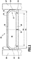
- FIG. 1 shows a spacer 10 according to the invention with a profile body made of plastic, which integrally with an outer wall forms a closed hollow profile 12, which has a substantially rectangular cross-section.
- the hollow profile 12 is typically produced by extrusion.
- the hollow profile 12 comprises two parallel side walls 14, 16 and an inner wall 18 extending between the side walls 14, 16 and an outer wall 20 adjoining the side walls 14, 16 and oriented essentially parallel to the inner wall 18.
- the outer wall 20 ends with two cranked ends Areas 21, 22 on the side walls 14 and 16 at.
- a first and a second primary reinforcement element 24, 26 are embedded in the form of a wire with a circular cross-section.
- the inner wall 18 has in the areas in which the reinforcing elements 24, 26 are embedded, a greater thickness than in the intermediate region.
- a circumferential diffusion barrier layer 26 is provided, which is substantially impermeable to water vapor and, for example, made of metal, in particular stainless steel.
- the diffusion barrier layer 26 may also be formed by a plastic film with corresponding properties or a coating, in particular a metallized coating, a coated plastic layer or an extruded plastic layer.
- the hollow profile 12 encloses a cavity 30, which communicates via passage openings 32 in the inner wall 18 with the volume enclosed in the insulating glass pane.
- the passage openings are regularly distributed in the longitudinal direction of the spacer 10.
- the hollow chamber 30 takes in the installed state of the spacer in an insulating glass on a desiccant, which serves to absorb moisture from the interior of the insulating glass pane.
- the spacer 10 of FIG. 1 has a relatively large width compared to its height, which can be for example 24 mm in reality, the height of the spacer is typically about 6 mm to about 7.5 mm.
- the distance A2 of the centroids of the cross-sectional areas of the primary reinforcing elements 24 and 26 is approximately 90% of the distance A1 between the side walls 14 and 16.
- the plastic material from which the hollow section 12 is made in the present case polypropylene (PP) and is free of reinforcing fibers.
- PP polypropylene
- the strength of the profile is determined essentially by the primary reinforcing elements 24, 26 and optionally by the diffusion barrier layer 26, if it consists of a metal layer in the form of a film, such as a steel foil.
- the thickness of the metal layer may be small and, for example, about 0.1 mm or less, for example about 0.05 to about 0.08 mm.
- the spacer 10 can be deformed by cold forming to corner areas, which are needed to form a rectangular frame, for example, which is inserted and glued between the two glass sheets 27, 28.
- FIGS. 2A to 2C three variants of a spacer 40 according to the invention are shown, which are used to distinguish in the FIGS. 2B and 2C as 40 'and 40 ", respectively.
- Like reference numerals are used for like profile features.
- the spacer 40 in FIG. 2A comprises a closed plastic hollow profile 42 with side walls 44, 46, which are arranged parallel to each other and between which an inner wall 48 and an outer wall 50, again here with bent portions 51, 52 extends. Again, the profile body of the side walls 44, 46 and the inner wall 48 is integrally extruded with the outer wall 50 and the cranked portions 51, 52.
- primary reinforcing elements 54, 56 are received on the inner wall 48 side, and the inner wall 48 is made in the region of the reinforcing elements 54, 56 with a greater thickness than in the area between them.
- the hollow profile 42 encloses a cavity 58, which can communicate via continuous perforation openings 60 with the outside of the inner wall 48.
- a metal foil 62 made of stainless steel is applied, in particular adhesively bonded, which acts as a diffusion barrier layer.
- the distance between the centers of gravity of the cross-sectional areas of the primary reinforcing elements 24, 26 and 54, 56 is at least 40% of the distance between the side walls or more, but at least 4 mm.
- the full cross-sectional area of the reinforcing elements 24, 26 is located in the inner wall 18.
- the diameter of the primary reinforcing elements 24, 26 and 54, 56 is about 0.8 mm, the thickness of the walls 14, 16 and 44, 46 about 0.9 mm. In the area where the primary reinforcing elements 24, 26 and 54, 56 are received, the thickness of the inner wall 18 and 48, respectively, is about 1.8 mm, i. about 2.2 times the diameter of the reinforcing elements.
- a non-inventive spacer 40 ' is shown having a hollow profile 42' extending from the hollow profile 42 of FIG. 2A only differs in that reinforcing elements 54 ', 56' in the cross section of the hollow profile 42 'are accommodated in a different position, so that its cross-sectional area approximately 50% in the first and second side wall 44' and 46 'is arranged.
- a spacer 40 "of the present invention in turn, the basic structure of the spacer of the FIG. 2A however, the primary reinforcing elements 54 "and 56" are closer in their center of gravity cross-sectional areas, but still maintain a distance of 40% of the distance between the side walls 44 "and 46" and at least 4 mm.
- the inner wall 48 is designed here over the entire width with a uniform thickness of 1.8 mm.
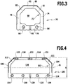
- FIG. 3 shows a spacer 70 according to the invention, which is built relatively narrow with a width of about 8 mm and with a height of about 7 mm has a nearly square cross-section.
- the spacer 70 comprises a closed hollow profile 72 with parallel side walls 74, 76 and between the side walls 74, 76 extending inner and outer walls 78, 80.
- the hollow profile of a profile body (side walls 74, 76 and inner wall 78) and the outer wall 80 is extruded as a one-piece body.
- the outer wall 80 is again connected via bent regions 81, 82 to the side walls 74 and 76, respectively.
- two primary reinforcing elements 84, 86 are arranged in the form of a wire with a circular cross-section, wherein the minimum distance of 4 mm of the centers of gravity of the cross-sectional areas of the reinforcing elements is maintained. Furthermore, the distance is approximately 65% of the distance between the side walls 74, 76.
- the hollow profile 72 includes a hollow volume 88, which is the filling with desiccants available.
- the desiccant in the hollow volume 88 communicates with the outer surface of the inner wall 78 via perforation through holes 90.
- a barrier layer 92 is arranged from a stainless steel foil.
- FIG. 4 shows a further embodiment of the present invention based on a variation of the geometry as in Figure 2C shown.
- the spacer 100 has a closed hollow profile 102 made of plastic material, in which side walls 104, 106 are arranged parallel to one another and wherein an inner wall 108 extends between these side walls 104, 106.
- the outer wall 110 connects via bent portions 111, 112 to the side walls 104 and 106, respectively.
- two further reinforcing elements 118, 120 are arranged, which are all made of a wire with a circular cross-section.
- reinforcing elements 121, 122, 123 are arranged in the outer wall 110, which are also wire-shaped but have an oval cross-section.
- the ratio of the cross-sectional areas of the reinforcing elements 114, 116, 118, 120 of the inner wall to the cross-sectional areas of the reinforcing elements 121, 122, 123 is about 1.2. Due to the further slight reinforcing effect of the barrier layer 124, the neutral axis N lies at approximately half the height H (50%) of the total cross section of the hollow profile 102.
- the solid profile 102 encloses a hollow volume 126 which can receive a desiccant.
- the hollow volume 126 is accessible via perforation through holes 128.
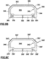
- FIG. 5A shows a spacer 140, which in its geometry from the spacer 40 of FIG. 2A derives and includes a closed Plastic hollow section 142 with side walls 144, 146 which are arranged parallel to each other and between which an inner wall 148 and an outer wall 150, again here with cranked areas 151, 152, extends.
- primary reinforcing elements 154, 156 are received on the side of the inner wall 148, and the inner wall 148 is made in the area of the reinforcing elements 154, 156 with a greater thickness than in the area between them.
- the hollow profile 140 encloses a cavity 158, which can communicate via through openings 160 with the outside of the inner wall 148.
- a metal foil 162 made of stainless steel is applied, in particular adhesively bonded, which acts as a diffusion barrier layer.
- the diameter of the primary reinforcing elements 154, 156 is about 0.8 mm, the thickness of the walls 144, 146 about 0.9 mm.
- the thickness of the inner wall 148 is about 1.8 mm, i. approximately 2.2 times the diameter of the reinforcing elements 154, 156.
- the spacer 140 has two further reinforcing elements 164, 166, which are formed as sheet metal strips.
- the reinforcing elements 164, 166 Due to the cross-section of the reinforcing elements 164, 166, they can be completely received in the wall of the side walls 144, 146, whose thickness can remain at the original dimension of about 0.9 mm.
- the neutral axis N is about 50% of the total height H of the hollow section 142, due to a suitable choice of the material of the barrier layer 162 and the layer thickness.
- FIG. 5B goes to the embodiment of FIG. 4 back, here a closed hollow profile 182 with side walls 184, 186, an inner wall 188 and an outer wall 190 with bent portions 191, 192, with which the outer wall 190 adjoins the side walls 184, 186, is formed.
- the side walls 184, 186 comprise reinforcing elements 204, 206, which are formed as sheet metal strips, so that they simply fit into the predetermined cross section of the side walls 184, 186.
- Oval formed reinforcing elements are received in the outer wall 190 and designated by the reference numerals 214, 216, 218.
- the hollow profile 182 encloses a hollow volume 210, which is accessible via passage openings 212 in the inner wall 188.
- a vapor barrier layer 202 is arranged on the outer wall 190.
- the reinforcing elements 204, 206 arranged in the side walls 184, 186 lie approximately in the region of the neutral axis of the spacer 180.
- the hollow profiles of the spacers 140 and 180 of the FIGS. 5A and 5B are each extruded in one piece.
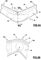
- FIGS. 6A to 6C show a bent to a corner portion 65 portion of the spacer 40 from FIG. 2A ,
- FIGS. 6A and 6B show the corner region 65 in a perspective view from the side of the outer wall 50 and the diffusion barrier 62 glued there or from the side of the inner wall 48.
- a bending punch (not shown), the width of which may be smaller than the extent of Inner wall 48 between the side walls 44, 46, pressed against the inner wall 48 and the spacer then bent to the punch by slightly more than 90 °, so that the corner portion 65 is obtained with extending at an angle of 90 ° legs 65a, 65b.
- FIG. 6C shows the corner region 65 in a sectional view along line VIa-VIa, partially supplemented around the outer contour of the spacer 40 before the cold deformation.
- the inner surfaces of the outer wall 50 and the inner wall 48 approach, depending on the geometry of the plastic hollow profile until it abuts each other.
- the originally present uniform cavity 58 is reduced and there remain two subspaces 58a, 58b.
- the deformation can be carried out without causing undesirable deformation of the side walls 44, 46 and without the primary reinforcing elements 54, 56, the cold deformation hinder.
- FIG. 3 shows a spacer 220 with a profile body 222, which is formed from a plastic material with side walls 224, 226 and an inner wall 228.
- the side walls 224, 226 carry at their free, the inner wall 228 facing away from the bent end wall portions 230, 232nd
- a metallic foil 236, which forms the outer wall of the hollow profile 234 together with the bent wall portions 230, 232.
- the metallic foil 236 serves as a diffusion barrier. It therefore also extends beyond the bent wall portions 230, 232 and covers large portions of the side walls 224, 226.
- first and second primary wire-shaped reinforcing members 238, 240 are embedded.
- the metallic foil 236 also acts as a further reinforcing element in this embodiment.
- the hollow volume 242 surrounded by the hollow profile 234 communicates via through openings 244 of the inner wall 228 with the intermediate disk space of an insulating glass unit formed using the spacer 220.
- Figure 8A shows a spacer 250 with a hollow profile body 252, which is formed of a plastic material with side walls 254, 256, an inner wall 258 and an outer wall 260.
- primary first and second reinforcement members 262, 264 are fully embedded.
- the portions of the inner wall that receive the primary reinforcement members 262, 264 have a greater thickness than the portion therebetween to completely embed the reinforcement members 262, 264 in the plastic material.
- the inner wall 258 has a reduced thickness in the areas 266, 268 directly adjacent to the side walls 254, 256, so that the inner wall 258 adjoins the side walls 254, 256 via a type of hinge. This ensures that the geometry of the side walls in a formation of corners as in the FIGS. 6A to 6C is substantially preserved, so that the system of the glass panes of the insulating glass pane is also optimized in the corner area.
- the outer contours of the primary first and second reinforcing elements keep a distance from the side walls which corresponds approximately to the diameter of the reinforcing elements, in the present case about 0.8 mm.
- the spacers of Figures 8B and 8C also have a closed hollow profile 342, 342 'with side walls 344, 346 which are arranged parallel to each other and between which an inner wall 348 and an outer wall 350 extends.
- the outer wall 350 is again connected via bent regions 351, 352 to the side walls 344 and 346, respectively.
- the profile body of the plastic hollow profile 342 is extruded in one piece as a whole.
- primary reinforcing elements 354, 356 are received on the side of the inner wall 348, and the inner wall 348 is made in the region of the reinforcing elements 354, 356 with a greater thickness than in the intermediate region of the profile center.
- the hollow profile 342 encloses a cavity 358, which can communicate via continuous perforation 360 with the outside of the inner wall 348, which is followed in the assembled state of an insulating glass pane of the insulating glass pane interior.
- a metal foil 362 preferably made of precious steel, applied, in particular glued, which acts as a diffusion barrier layer.
- FIGS FIG. 2A in the spacer 340 on the side of the inner wall 348 at regular intervals along the length of the spacer profile 340 through holes 364, 366 arranged on the one hand in addition to the perforation 360 a gas exchange between the hollow chamber 358 and the outside of the inner wall 348 and the interior of the later allow produced insulating glass pane.
- the spacer 340 has the FIG. 8C but no additional through holes 364, 366, but groove-like recesses 368 ', 370', which extend on the outside of the inner wall 348 'in the longitudinal direction of the spacer 340'.
Landscapes
- Engineering & Computer Science (AREA)
- Civil Engineering (AREA)
- Structural Engineering (AREA)
- Joining Of Glass To Other Materials (AREA)
- Securing Of Glass Panes Or The Like (AREA)
- Building Environments (AREA)
- Floor Finish (AREA)
Claims (16)
- Espaceur (10) pour des vitrages isolants, comportant un corps profilé en matière plastique, lequel présente une section transversale sensiblement rectangulaire pourvue de première et deuxième parois latérales (14, 16) agencées parallèlement l'une à l'autre et d'une paroi latérale (18) s'étendant entre la première et la deuxième paroi latérale, ainsi qu'une paroi extérieure (20) s'étendant entre la première et la deuxième paroi latérale (14, 16) sensiblement parallèlement à la paroi intérieure, laquelle paroi extérieure forme avec le corps profilé un profilé creux (12) fermé, dans lequel un premier et un deuxième élément de renforcement primaire (24, 26) en forme de fil sont agencés parallèlement à la direction axiale du profilé d'espaceur (10) dans la paroi intérieure (18), caractérisé en ce que les premier et deuxième éléments de renforcement primaires (24, 26) sont agencés exclusivement dans la zone de la paroi intérieure (18) et maintiennent avec leurs contours extérieurs un écart prédéfini par rapport aux parois latérales, en ce que l'écart entre les centres de gravité des surfaces de section des premier et deuxième éléments de renforcement primaires (24, 26) atteint 40 % ou plus de l'écart entre les parois latérales (14, 16), mais au moins environ 4 mm,
et en ce que les premier et deuxième éléments de renforcement primaires (24, 26) sont agencés respectivement au voisinage d'une partie du volume creux du profilé creux (12), dans lequel, une fois le profilé creux (12) fléchi de 90° autour d'un axe de fléchissement s'étendant perpendiculairement à la direction longitudinale et parallèlement à la paroi intérieure (18), la paroi intérieure (18) et la paroi extérieure (20) sont écartées l'une de l'autre. - Espaceur selon la revendication 1, caractérisé en ce que la paroi extérieure (20) est fabriquée en matière plastique, dans lequel la matière plastique de la paroi extérieure (20) est de préférence compatible avec la matière plastique du profilé creux ou identique à celle-ci et dans lequel, plus préférentiellement, la paroi extérieure (20) est réalisée d'une seule pièce avec le profilé creux, en particulier extrudée.
- Espaceur selon la revendication 1 ou 2, caractérisé en ce que l'écart entre les centres de gravité des surfaces de section des éléments de renforcement primaires (24, 26) atteint environ 50 % ou plus de l'écart entre les parois latérales (14, 16), mais au moins environ 5 mm.
- Espaceur selon l'une quelconque des revendications 1 à 3, caractérisé en ce que la section transversale des éléments de renforcement primaires (24, 26) en forme de fil est polygonale, ronde ou ovale, dans lequel de préférence la surface des éléments de renforcement primaires est structurée, en particulier moletée, cannelée ou pourvue d'une structure filetée extérieure, et/ou équipée d'une couche d'agent de couplage.
- Espaceur selon l'une quelconque des revendications 1 à 4, caractérisé en ce qu'au moins la paroi extérieure (20) est pourvue d'une barrière de diffusion ou forme celle-ci, dans lequel la barrière de diffusion est sélectionnée en particulier parmi une feuille de métal ou de matière plastique imperméable à la vapeur d'eau, une couche de métal appliquée sur le profilé creux (12) ou une couche de matière plastique appliquée sur le profilé creux (12) ou le cas échéant co-extrudée avec celui-ci.
- Espaceur selon l'une quelconque des revendications 1 à 5, caractérisé en ce que la matière plastique du profilé creux (12) est à base de PP, de PC, de PVC, de SAN, de polyester, de PA et/ou d'ABS.
- Espaceur selon l'une quelconque des revendications 1 à 6, caractérisé en ce que le rapport pondéral du poids des éléments de renforcement primaires (24, 26) sur le poids de la matière plastique atteint environ 1:6 à environ 2:1.
- Espaceur selon l'une quelconque des revendications 1 à 7, caractérisé en ce que la matière plastique présente une teneur en fibres de renforcement qui atteint environ 20 % en poids ou moins, en particulier environ 10 % en poids ou moins, dans lequel la matière plastique est le cas échéant sensiblement exempte de fibres de renforcement.
- Espaceur selon l'une quelconque des revendications 1 à 8, caractérisé en ce que la matière plastique comporte des additifs, en particulier sélectionnés parmi des charges, des pigments, des stabilisants lumière, des modifiants choc, des antistatiques et/ou des retardateurs de flamme.
- Espaceur selon l'une quelconque des revendications 1 à 9, caractérisé en ce que la paroi intérieure (18) présente, au moins dans ses zones dans lesquelles les premier et deuxième éléments de renforcement primaires (24, 26) sont agencés, une épaisseur qui atteint environ 1 à environ 2,5 fois, en particulier environ 1,5 à environ 2,5 fois l'étendue de la section transversale des éléments de renforcement primaires (24, 26) dans cette direction.
- Espaceur selon l'une quelconque des revendications 1 à 10, caractérisé en ce que l'épaisseur de la paroi intérieure (18) dans une zone centrale située entre les éléments de renforcement primaires (24, 26) est plus petite que dans les zones dans lesquelles les éléments de renforcement primaires (24, 26) sont agencés.
- Espaceur selon l'une quelconque des revendications 1 à 11, caractérisé en ce que l'épaisseur de la paroi intérieure (258) directement au voisinage des parois latérales (254, 256) est réduite par rapport à la zone de la paroi intérieure (258) située dans le prolongement de celle-ci en direction du centre du profilé, dans lequel de préférence les premier et deuxième éléments de renforcement primaires (262, 264) sont agencés entièrement dans la zone de la paroi intérieure (258) avec leur section transversale.
- Espaceur selon l'une quelconque des revendications 1 à 12, caractérisé en ce que d'autres éléments de renforcement primaires (214, 216, 218) en particulier également en forme de fil, sont agencés dans le profilé creux en plus des premier et deuxième éléments de renforcement primaires (198, 200),
dans lequel éventuellement au moins l'un des autres éléments de renforcement est agencé sur et/ou dans la paroi extérieure (190),
dans lequel de préférence le rapport des surfaces de section additionnées de tous les éléments de renforcement de la paroi intérieure sur la surface de section additionnée des éléments de renforcement de la paroi extérieure atteint environ 2:1 à environ 1:2, et
dans lequel éventuellement l'élément ou les éléments de renforcement (214, 216, 218), qui sont agencés dans la zone de la paroi extérieure, présentent un allongement à la rupture plus grand que celui des éléments de renforcement (198, 200) agencés dans la zone de la paroi intérieure. - Espaceur selon l'une quelconque des revendications 1 à 13, caractérisé en ce que le profilé creux présente lors d'un fléchissement un axe neutre perpendiculaire à la direction longitudinale et parallèle à la paroi intérieure, lequel se situe dans la plage d'environ 40 % à environ 60 % de la hauteur totale du profilé creux.
- Espaceur selon l'une quelconque des revendications 1 à 14, caractérisé en ce que le profilé présente un angle de sur-fléchissement, pour l'obtention d'une partie fléchie de 90°, qui atteint environ 20° ou moins.
- Espaceur selon la revendication 1, caractérisé en ce que la paroi extérieure (236) même est réalisée sous la forme d'un élément de renforcement (236) et le cas échéant sous la forme d'une barrière de diffusion, dans lequel la paroi extérieure est formée de préférence d'une feuille métallique (236) .
Priority Applications (1)
| Application Number | Priority Date | Filing Date | Title |
|---|---|---|---|
| PL13732187T PL2870313T3 (pl) | 2012-07-04 | 2013-06-28 | Element dystansowy dla szyb zespolonych |
Applications Claiming Priority (3)
| Application Number | Priority Date | Filing Date | Title |
|---|---|---|---|
| DE201210105960 DE102012105960A1 (de) | 2012-07-04 | 2012-07-04 | Abstandhalter fuer Isolierglasscheiben |
| DE201220104026 DE202012104026U1 (de) | 2012-07-04 | 2012-10-19 | Abstandhalter für Isolierglasscheiben |
| PCT/EP2013/063691 WO2014005950A1 (fr) | 2012-07-04 | 2013-06-28 | Entretoise destinée à des vitrages isolants |
Publications (2)
| Publication Number | Publication Date |
|---|---|
| EP2870313A1 EP2870313A1 (fr) | 2015-05-13 |
| EP2870313B1 true EP2870313B1 (fr) | 2018-10-10 |
Family
ID=49547274
Family Applications (1)
| Application Number | Title | Priority Date | Filing Date |
|---|---|---|---|
| EP13732187.3A Active EP2870313B1 (fr) | 2012-07-04 | 2013-06-28 | Entretoise destinée à des vitrages isolants |
Country Status (7)
| Country | Link |
|---|---|
| US (1) | US9683404B2 (fr) |
| EP (1) | EP2870313B1 (fr) |
| CN (1) | CN104428479B (fr) |
| DE (2) | DE102012105960A1 (fr) |
| DK (1) | DK2870313T3 (fr) |
| PL (1) | PL2870313T3 (fr) |
| WO (1) | WO2014005950A1 (fr) |
Families Citing this family (24)
| Publication number | Priority date | Publication date | Assignee | Title |
|---|---|---|---|---|
| CN105579653A (zh) | 2013-09-30 | 2016-05-11 | 法国圣戈班玻璃厂 | 用于隔热玻璃的间隔件 |
| CN105793511A (zh) * | 2013-12-12 | 2016-07-20 | 法国圣戈班玻璃厂 | 具有经挤出的密封型材的用于绝缘窗玻璃的距离保持件 |
| US10190359B2 (en) | 2013-12-12 | 2019-01-29 | Saint-Gobain Glass France | Double glazing having improved sealing |
| TR201815606T4 (tr) | 2014-06-27 | 2018-11-21 | Saint Gobain | Mesafe parçasına sahip yalıtım cam kaplaması ve bunun imal edilmesi için yöntem ve ayrıca bunun bina cam kaplaması olarak kullanımı. |
| US10301868B2 (en) | 2014-06-27 | 2019-05-28 | Saint-Gobain Glass France | Insulated glazing comprising a spacer, and production method |
| BR112017003684B1 (pt) | 2014-09-25 | 2022-04-05 | Saint-Gobain Glass France | Espaçador para unidades de envidraçamento isolantes |
| US10508486B2 (en) | 2015-03-02 | 2019-12-17 | Saint Gobain Glass France | Glass-fiber-reinforced spacer for insulating glazing unit |
| WO2016150705A1 (fr) * | 2015-03-20 | 2016-09-29 | Saint-Gobain Glass France | Intercalaire pour vitrage isolant à étanchéité accrue |
| CN104912448A (zh) * | 2015-06-18 | 2015-09-16 | 无锡市新颖密封材料厂 | 一种玻璃防撞密封条 |
| CH711479B1 (de) * | 2015-08-31 | 2018-08-15 | Marco Semadeni Dr | Bauelement mit Hohlglasbausteinen. |
| CN105113939B (zh) * | 2015-09-08 | 2017-06-16 | 双城市森鹰窗业有限公司 | 一种多层中空玻璃 |
| DE102015122714A1 (de) | 2015-12-23 | 2017-07-27 | Ensinger Gmbh | Abstandhalter für Isolierglasscheiben |
| DE202015010024U1 (de) | 2015-12-23 | 2023-08-16 | Alu Pro S.R.L. | Abstandhalter für Isolierglasscheiben |
| DE102016115023A1 (de) * | 2015-12-23 | 2017-06-29 | Ensinger Gmbh | Abstandhalter für Isolierglasscheiben |
| CN105672832B (zh) * | 2016-03-17 | 2018-03-02 | 大连华工创新科技股份有限公司 | 中空玻璃隔热条及中空玻璃 |
| CN105672833B (zh) * | 2016-03-17 | 2018-03-27 | 大连华工创新科技股份有限公司 | 中空玻璃隔热条及制造设备 |
| CN105696917B (zh) * | 2016-03-17 | 2018-07-31 | 大连华工创新科技股份有限公司 | 一种中空玻璃隔热条及中空玻璃 |
| FR3048860B1 (fr) * | 2016-03-18 | 2018-07-27 | Saint-Gobain Glass France | Vitrage isolant notamment pour enceinte climatique |
| FR3048862B1 (fr) * | 2016-03-18 | 2018-04-06 | Saint- Gobain Glass France | Vitrage isolant notamment pour enceinte climatique |
| PL3440299T3 (pl) * | 2016-04-05 | 2021-09-27 | Saint-Gobain Glass France | Szyba zespolona do mebla chłodniczego |
| CN106121460A (zh) * | 2016-08-11 | 2016-11-16 | 江苏扬子净化工程有限公司 | 一种节能隔音双层玻璃洁净窗 |
| DK179586B1 (en) * | 2016-10-13 | 2019-02-20 | Vkr Holding A/S | A frame member, a method for making a frame member, a frame structure and use of a frame member |
| CN106593220A (zh) * | 2016-12-09 | 2017-04-26 | 盘锦中屏科技有限公司 | 一种既有玻璃窗改造而成的节能降噪玻璃窗及其改造方法 |
| CO2017007432A1 (es) * | 2017-03-27 | 2017-11-10 | Agp America Sa | Cristal automotriz laminado resistente a la intrusión |
Citations (2)
| Publication number | Priority date | Publication date | Assignee | Title |
|---|---|---|---|---|
| DE19961902A1 (de) * | 1999-12-20 | 2001-07-05 | Wilfried Ensinger | Kunststoff-Abstandshalterrahmen und Verfahren zu ihrer Herstellung |
| DE10226269A1 (de) * | 2002-03-06 | 2003-10-02 | Ensinger Kunststofftechnologie | Abstandhalter |
Family Cites Families (22)
| Publication number | Priority date | Publication date | Assignee | Title |
|---|---|---|---|---|
| AT380527B (de) * | 1982-01-21 | 1986-06-10 | Peter Lisec | Verfahren zur herstellung von abstandhalterrahmen fuer isolierglas |
| GB2162228B (en) | 1984-07-25 | 1987-07-15 | Sanden Corp | Double-glazed window for a refrigerator |
| DK77688D0 (da) * | 1988-02-15 | 1988-02-15 | Claus Roulund | Fremgangsmaade til bukning af afstandsprofiler til termoruder, eller lignende hulprofiler med i det vaesentlige firkantet tvaersnit, apparat til udoevelse af fremgangsmaaden samt produkt fremstillet ved fremgangsmaaden |
| US5106663A (en) * | 1989-03-07 | 1992-04-21 | Tremco Incorporated | Double-paned window system having controlled sealant thickness |
| GB9218150D0 (en) * | 1992-08-26 | 1992-10-14 | Pilkington Glass Ltd | Insulating units |
| DE9214799U1 (fr) | 1992-10-31 | 1992-12-24 | Kaufmann Gmbh & Co. Kg, 7963 Altshausen, De | |
| DE9303795U1 (de) | 1993-03-16 | 1994-07-14 | Roller Ulrike | Abstandshalter |
| EP0601488B1 (fr) | 1992-12-10 | 1997-05-02 | Thermix GmbH Isolationssysteme für Verglasungen | Elément d'espacement |
| US5514432A (en) * | 1993-07-14 | 1996-05-07 | Lisec; Peter | Hollow profile for spacer frames for insulating glass panes |
| IT1273918B (it) * | 1994-10-31 | 1997-07-11 | For El Base Di Vianello Fortun | Procedimento e dispositivo automatici per la calandratura di profili in alluminio per la formazione di telai distanziatori per pannelli di vetro isolante |
| US5640828A (en) * | 1995-02-15 | 1997-06-24 | Weather Shield Mfg., Inc. | Spacer for an insulated window panel assembly |
| DE29723777U1 (de) * | 1996-07-11 | 1999-04-01 | Woschko Manfred | Rahmenlose Tür- oder Fensterflügelanordnung mit Isolierverglasung |
| DE19807545A1 (de) | 1996-10-23 | 1999-08-26 | Mauer Gmbh | Elektrisch gesteuertes Wertfachschloß |
| DE19805348A1 (de) | 1998-02-11 | 1999-08-12 | Caprano & Brunnhofer | Abstandhalterprofil für Isolierscheibeneinheit |
| CA2269110A1 (fr) * | 1998-04-27 | 1999-10-27 | Flachglas Aktiengesellschaft | Profil d'espacement d'une unite a double vitrage |
| AU2003206770A1 (en) | 2002-03-06 | 2003-09-16 | Ensinger Kunststofftechnologie Gbr | Spacers |
| DE202006000835U1 (de) * | 2006-01-19 | 2006-04-06 | Seele Gmbh & Co. Kg | Isolierscheibe mit verstärktem Randverbund |
| DE602006010199D1 (de) * | 2006-08-11 | 2009-12-17 | Rolltech As | Abstandhalter für Glasscheiben und ein Verfahren zur Herstellung eines solchen Abstandhalters |
| DE102008033249A1 (de) * | 2008-07-15 | 2010-01-21 | Gssg Holding Gmbh & Co. Kg | Isolierglasscheibe |
| CN101550795A (zh) * | 2009-05-06 | 2009-10-07 | 沈阳化工学院 | 可保暖、增强的中空玻璃间隔条 |
| DE102010006127A1 (de) | 2010-01-29 | 2011-08-04 | Technoform Glass Insulation Holding GmbH, 34277 | Abstandshalterprofil mit Verstärkungsschicht |
| DE102010049806A1 (de) * | 2010-10-27 | 2012-05-03 | Technoform Glass Insulation Holding Gmbh | Abstandshalterprofil und Isolierscheibeneinheit mit einem solchen Abstandshalterprofil |
-
2012
- 2012-07-04 DE DE201210105960 patent/DE102012105960A1/de active Pending
- 2012-10-19 DE DE201220104026 patent/DE202012104026U1/de not_active Expired - Lifetime
-
2013
- 2013-06-28 EP EP13732187.3A patent/EP2870313B1/fr active Active
- 2013-06-28 WO PCT/EP2013/063691 patent/WO2014005950A1/fr active Application Filing
- 2013-06-28 DK DK13732187.3T patent/DK2870313T3/en active
- 2013-06-28 PL PL13732187T patent/PL2870313T3/pl unknown
- 2013-06-28 CN CN201380035322.3A patent/CN104428479B/zh active Active
-
2014
- 2014-12-22 US US14/579,520 patent/US9683404B2/en active Active
Patent Citations (2)
| Publication number | Priority date | Publication date | Assignee | Title |
|---|---|---|---|---|
| DE19961902A1 (de) * | 1999-12-20 | 2001-07-05 | Wilfried Ensinger | Kunststoff-Abstandshalterrahmen und Verfahren zu ihrer Herstellung |
| DE10226269A1 (de) * | 2002-03-06 | 2003-10-02 | Ensinger Kunststofftechnologie | Abstandhalter |
Also Published As
| Publication number | Publication date |
|---|---|
| DK2870313T3 (en) | 2019-02-04 |
| WO2014005950A1 (fr) | 2014-01-09 |
| CN104428479B (zh) | 2017-07-18 |
| PL2870313T3 (pl) | 2019-04-30 |
| US9683404B2 (en) | 2017-06-20 |
| EP2870313A1 (fr) | 2015-05-13 |
| US20150107167A1 (en) | 2015-04-23 |
| DE202012104026U1 (de) | 2013-10-07 |
| CN104428479A (zh) | 2015-03-18 |
| DE102012105960A1 (de) | 2014-01-09 |
Similar Documents
| Publication | Publication Date | Title |
|---|---|---|
| EP2870313B1 (fr) | Entretoise destinée à des vitrages isolants | |
| EP3162999B1 (fr) | Profilé d'écartement et ensemble vitrage isolant avec un tel profilé d'écartement | |
| EP2408990B9 (fr) | Profilé écarteur à couche de renforcement | |
| EP1529920B1 (fr) | Profilé espaceur pour vitrage isolant | |
| EP2079895B1 (fr) | Profilé extrudé à cavité pour porte ou fenêtre | |
| DE102011009359A1 (de) | Abstandshalterprofil und Isolierscheibeneinheit mit einem solchen Abstandshalterprofil | |
| EP3394378B1 (fr) | Élément intercalaire pour vitrages isolants | |
| EP1017923A1 (fr) | Profile d'ecartement pour ensemble vitrage isolant | |
| DE102006017821A1 (de) | Eckverbinder für Glasscheiben-Abstandhalter | |
| EP2406454A1 (fr) | Ecarteur pour vitrages isolants | |
| WO2017108241A9 (fr) | Élément intercalaire pour vitrages isolants | |
| EP2490576B1 (fr) | Dispositif de thermorégulation comportant ce cadre | |
| EP0989277A2 (fr) | Porte, notamment une porte coupe-feu | |
| EP2630321B1 (fr) | Procédé pour introduire un matériau isolant dans des profilés à chambre creuse et profilé à chambre creuse correspondant | |
| EP4325018A1 (fr) | Profilé métallique isolé thermiquement avec nervures isolantes pour relier deux éléments profilés et traverses de pont pour relier deux barrettes isolantes | |
| DE202022002741U1 (de) | Kaltbiegbarer Abstandhalter mit verbesserter Steifigkeit | |
| WO2023198709A1 (fr) | Entretoise à rigidité mécanique améliorée | |
| DE202015010024U1 (de) | Abstandhalter für Isolierglasscheiben | |
| WO2012079722A1 (fr) | Procédé d'introduction d'un matériau isolant dans des profilés creux et profilé creux | |
| EP2453096A2 (fr) | Dispositif de cadre coulissant |
Legal Events
| Date | Code | Title | Description |
|---|---|---|---|
| PUAI | Public reference made under article 153(3) epc to a published international application that has entered the european phase |
Free format text: ORIGINAL CODE: 0009012 |
|
| 17P | Request for examination filed |
Effective date: 20141215 |
|
| AK | Designated contracting states |
Kind code of ref document: A1 Designated state(s): AL AT BE BG CH CY CZ DE DK EE ES FI FR GB GR HR HU IE IS IT LI LT LU LV MC MK MT NL NO PL PT RO RS SE SI SK SM TR |
|
| AX | Request for extension of the european patent |
Extension state: BA ME |
|
| DAX | Request for extension of the european patent (deleted) | ||
| STAA | Information on the status of an ep patent application or granted ep patent |
Free format text: STATUS: EXAMINATION IS IN PROGRESS |
|
| 17Q | First examination report despatched |
Effective date: 20170111 |
|
| GRAP | Despatch of communication of intention to grant a patent |
Free format text: ORIGINAL CODE: EPIDOSNIGR1 |
|
| STAA | Information on the status of an ep patent application or granted ep patent |
Free format text: STATUS: GRANT OF PATENT IS INTENDED |
|
| INTG | Intention to grant announced |
Effective date: 20180412 |
|
| GRAS | Grant fee paid |
Free format text: ORIGINAL CODE: EPIDOSNIGR3 |
|
| GRAJ | Information related to disapproval of communication of intention to grant by the applicant or resumption of examination proceedings by the epo deleted |
Free format text: ORIGINAL CODE: EPIDOSDIGR1 |
|
| GRAL | Information related to payment of fee for publishing/printing deleted |
Free format text: ORIGINAL CODE: EPIDOSDIGR3 |
|
| STAA | Information on the status of an ep patent application or granted ep patent |
Free format text: STATUS: EXAMINATION IS IN PROGRESS |
|
| GRAR | Information related to intention to grant a patent recorded |
Free format text: ORIGINAL CODE: EPIDOSNIGR71 |
|
| INTC | Intention to grant announced (deleted) | ||
| STAA | Information on the status of an ep patent application or granted ep patent |
Free format text: STATUS: GRANT OF PATENT IS INTENDED |
|
| GRAA | (expected) grant |
Free format text: ORIGINAL CODE: 0009210 |
|
| STAA | Information on the status of an ep patent application or granted ep patent |
Free format text: STATUS: THE PATENT HAS BEEN GRANTED |
|
| AK | Designated contracting states |
Kind code of ref document: B1 Designated state(s): AL AT BE BG CH CY CZ DE DK EE ES FI FR GB GR HR HU IE IS IT LI LT LU LV MC MK MT NL NO PL PT RO RS SE SI SK SM TR |
|
| INTG | Intention to grant announced |
Effective date: 20180905 |
|
| REG | Reference to a national code |
Ref country code: GB Ref legal event code: FG4D Free format text: NOT ENGLISH |
|
| REG | Reference to a national code |
Ref country code: CH Ref legal event code: EP Ref country code: AT Ref legal event code: REF Ref document number: 1051455 Country of ref document: AT Kind code of ref document: T Effective date: 20181015 |
|
| REG | Reference to a national code |
Ref country code: IE Ref legal event code: FG4D Free format text: LANGUAGE OF EP DOCUMENT: GERMAN |
|
| REG | Reference to a national code |
Ref country code: DE Ref legal event code: R096 Ref document number: 502013011295 Country of ref document: DE |
|
| REG | Reference to a national code |
Ref country code: CH Ref legal event code: NV Representative=s name: ISLER AND PEDRAZZINI AG, CH |
|
| REG | Reference to a national code |
Ref country code: RO Ref legal event code: EPE |
|
| REG | Reference to a national code |
Ref country code: NL Ref legal event code: FP |
|
| REG | Reference to a national code |
Ref country code: DK Ref legal event code: T3 Effective date: 20190128 |
|
| REG | Reference to a national code |
Ref country code: LT Ref legal event code: MG4D |
|
| PG25 | Lapsed in a contracting state [announced via postgrant information from national office to epo] |
Ref country code: IS Free format text: LAPSE BECAUSE OF FAILURE TO SUBMIT A TRANSLATION OF THE DESCRIPTION OR TO PAY THE FEE WITHIN THE PRESCRIBED TIME-LIMIT Effective date: 20190210 Ref country code: ES Free format text: LAPSE BECAUSE OF FAILURE TO SUBMIT A TRANSLATION OF THE DESCRIPTION OR TO PAY THE FEE WITHIN THE PRESCRIBED TIME-LIMIT Effective date: 20181010 Ref country code: LT Free format text: LAPSE BECAUSE OF FAILURE TO SUBMIT A TRANSLATION OF THE DESCRIPTION OR TO PAY THE FEE WITHIN THE PRESCRIBED TIME-LIMIT Effective date: 20181010 Ref country code: HR Free format text: LAPSE BECAUSE OF FAILURE TO SUBMIT A TRANSLATION OF THE DESCRIPTION OR TO PAY THE FEE WITHIN THE PRESCRIBED TIME-LIMIT Effective date: 20181010 Ref country code: NO Free format text: LAPSE BECAUSE OF FAILURE TO SUBMIT A TRANSLATION OF THE DESCRIPTION OR TO PAY THE FEE WITHIN THE PRESCRIBED TIME-LIMIT Effective date: 20190110 Ref country code: BG Free format text: LAPSE BECAUSE OF FAILURE TO SUBMIT A TRANSLATION OF THE DESCRIPTION OR TO PAY THE FEE WITHIN THE PRESCRIBED TIME-LIMIT Effective date: 20190110 Ref country code: LV Free format text: LAPSE BECAUSE OF FAILURE TO SUBMIT A TRANSLATION OF THE DESCRIPTION OR TO PAY THE FEE WITHIN THE PRESCRIBED TIME-LIMIT Effective date: 20181010 Ref country code: FI Free format text: LAPSE BECAUSE OF FAILURE TO SUBMIT A TRANSLATION OF THE DESCRIPTION OR TO PAY THE FEE WITHIN THE PRESCRIBED TIME-LIMIT Effective date: 20181010 |
|
| PG25 | Lapsed in a contracting state [announced via postgrant information from national office to epo] |
Ref country code: SE Free format text: LAPSE BECAUSE OF FAILURE TO SUBMIT A TRANSLATION OF THE DESCRIPTION OR TO PAY THE FEE WITHIN THE PRESCRIBED TIME-LIMIT Effective date: 20181010 Ref country code: RS Free format text: LAPSE BECAUSE OF FAILURE TO SUBMIT A TRANSLATION OF THE DESCRIPTION OR TO PAY THE FEE WITHIN THE PRESCRIBED TIME-LIMIT Effective date: 20181010 Ref country code: AL Free format text: LAPSE BECAUSE OF FAILURE TO SUBMIT A TRANSLATION OF THE DESCRIPTION OR TO PAY THE FEE WITHIN THE PRESCRIBED TIME-LIMIT Effective date: 20181010 Ref country code: GR Free format text: LAPSE BECAUSE OF FAILURE TO SUBMIT A TRANSLATION OF THE DESCRIPTION OR TO PAY THE FEE WITHIN THE PRESCRIBED TIME-LIMIT Effective date: 20190111 Ref country code: PT Free format text: LAPSE BECAUSE OF FAILURE TO SUBMIT A TRANSLATION OF THE DESCRIPTION OR TO PAY THE FEE WITHIN THE PRESCRIBED TIME-LIMIT Effective date: 20190210 |
|
| REG | Reference to a national code |
Ref country code: DE Ref legal event code: R097 Ref document number: 502013011295 Country of ref document: DE |
|
| PG25 | Lapsed in a contracting state [announced via postgrant information from national office to epo] |
Ref country code: CZ Free format text: LAPSE BECAUSE OF FAILURE TO SUBMIT A TRANSLATION OF THE DESCRIPTION OR TO PAY THE FEE WITHIN THE PRESCRIBED TIME-LIMIT Effective date: 20181010 |
|
| PLBE | No opposition filed within time limit |
Free format text: ORIGINAL CODE: 0009261 |
|
| STAA | Information on the status of an ep patent application or granted ep patent |
Free format text: STATUS: NO OPPOSITION FILED WITHIN TIME LIMIT |
|
| PG25 | Lapsed in a contracting state [announced via postgrant information from national office to epo] |
Ref country code: SM Free format text: LAPSE BECAUSE OF FAILURE TO SUBMIT A TRANSLATION OF THE DESCRIPTION OR TO PAY THE FEE WITHIN THE PRESCRIBED TIME-LIMIT Effective date: 20181010 Ref country code: EE Free format text: LAPSE BECAUSE OF FAILURE TO SUBMIT A TRANSLATION OF THE DESCRIPTION OR TO PAY THE FEE WITHIN THE PRESCRIBED TIME-LIMIT Effective date: 20181010 Ref country code: SK Free format text: LAPSE BECAUSE OF FAILURE TO SUBMIT A TRANSLATION OF THE DESCRIPTION OR TO PAY THE FEE WITHIN THE PRESCRIBED TIME-LIMIT Effective date: 20181010 |
|
| 26N | No opposition filed |
Effective date: 20190711 |
|
| PG25 | Lapsed in a contracting state [announced via postgrant information from national office to epo] |
Ref country code: SI Free format text: LAPSE BECAUSE OF FAILURE TO SUBMIT A TRANSLATION OF THE DESCRIPTION OR TO PAY THE FEE WITHIN THE PRESCRIBED TIME-LIMIT Effective date: 20181010 |
|
| PG25 | Lapsed in a contracting state [announced via postgrant information from national office to epo] |
Ref country code: MC Free format text: LAPSE BECAUSE OF FAILURE TO SUBMIT A TRANSLATION OF THE DESCRIPTION OR TO PAY THE FEE WITHIN THE PRESCRIBED TIME-LIMIT Effective date: 20181010 |
|
| PGFP | Annual fee paid to national office [announced via postgrant information from national office to epo] |
Ref country code: DK Payment date: 20191230 Year of fee payment: 7 |
|
| REG | Reference to a national code |
Ref country code: BE Ref legal event code: MM Effective date: 20190630 |
|
| REG | Reference to a national code |
Ref country code: DE Ref legal event code: R082 Ref document number: 502013011295 Country of ref document: DE Representative=s name: HOEGER, STELLRECHT & PARTNER PATENTANWAELTE MB, DE Ref country code: DE Ref legal event code: R081 Ref document number: 502013011295 Country of ref document: DE Owner name: ALU PRO S.R.L., IT Free format text: FORMER OWNER: ENSINGER GMBH, 71154 NUFRINGEN, DE |
|
| PG25 | Lapsed in a contracting state [announced via postgrant information from national office to epo] |
Ref country code: IE Free format text: LAPSE BECAUSE OF NON-PAYMENT OF DUE FEES Effective date: 20190628 |
|
| REG | Reference to a national code |
Ref country code: CH Ref legal event code: PUE Owner name: ALU PRO S.R.L., IT Free format text: FORMER OWNER: ENSINGER GMBH, DE |
|
| PG25 | Lapsed in a contracting state [announced via postgrant information from national office to epo] |
Ref country code: LU Free format text: LAPSE BECAUSE OF NON-PAYMENT OF DUE FEES Effective date: 20190628 Ref country code: BE Free format text: LAPSE BECAUSE OF NON-PAYMENT OF DUE FEES Effective date: 20190630 |
|
| REG | Reference to a national code |
Ref country code: GB Ref legal event code: 732E Free format text: REGISTERED BETWEEN 20200507 AND 20200513 |
|
| REG | Reference to a national code |
Ref country code: NL Ref legal event code: PD Owner name: ALU PRO S.R.L.; IT Free format text: DETAILS ASSIGNMENT: CHANGE OF OWNER(S), ASSIGNMENT; FORMER OWNER NAME: ENSINGER GMBH Effective date: 20200507 |
|
| REG | Reference to a national code |
Ref country code: AT Ref legal event code: PC Ref document number: 1051455 Country of ref document: AT Kind code of ref document: T Owner name: ALU PRO S.R.L., IT Effective date: 20200626 |
|
| REG | Reference to a national code |
Ref country code: DK Ref legal event code: EBP Effective date: 20200630 |
|
| PG25 | Lapsed in a contracting state [announced via postgrant information from national office to epo] |
Ref country code: CY Free format text: LAPSE BECAUSE OF FAILURE TO SUBMIT A TRANSLATION OF THE DESCRIPTION OR TO PAY THE FEE WITHIN THE PRESCRIBED TIME-LIMIT Effective date: 20181010 |
|
| PG25 | Lapsed in a contracting state [announced via postgrant information from national office to epo] |
Ref country code: HU Free format text: LAPSE BECAUSE OF FAILURE TO SUBMIT A TRANSLATION OF THE DESCRIPTION OR TO PAY THE FEE WITHIN THE PRESCRIBED TIME-LIMIT; INVALID AB INITIO Effective date: 20130628 Ref country code: MT Free format text: LAPSE BECAUSE OF FAILURE TO SUBMIT A TRANSLATION OF THE DESCRIPTION OR TO PAY THE FEE WITHIN THE PRESCRIBED TIME-LIMIT Effective date: 20181010 |
|
| PG25 | Lapsed in a contracting state [announced via postgrant information from national office to epo] |
Ref country code: DK Free format text: LAPSE BECAUSE OF NON-PAYMENT OF DUE FEES Effective date: 20200630 |
|
| PG25 | Lapsed in a contracting state [announced via postgrant information from national office to epo] |
Ref country code: MK Free format text: LAPSE BECAUSE OF FAILURE TO SUBMIT A TRANSLATION OF THE DESCRIPTION OR TO PAY THE FEE WITHIN THE PRESCRIBED TIME-LIMIT Effective date: 20181010 |
|
| P01 | Opt-out of the competence of the unified patent court (upc) registered |
Effective date: 20230601 |
|
| PGFP | Annual fee paid to national office [announced via postgrant information from national office to epo] |
Ref country code: RO Payment date: 20230607 Year of fee payment: 11 Ref country code: NL Payment date: 20230612 Year of fee payment: 11 Ref country code: FR Payment date: 20230620 Year of fee payment: 11 Ref country code: DE Payment date: 20230607 Year of fee payment: 11 |
|
| PGFP | Annual fee paid to national office [announced via postgrant information from national office to epo] |
Ref country code: TR Payment date: 20230612 Year of fee payment: 11 Ref country code: PL Payment date: 20230627 Year of fee payment: 11 |
|
| PGFP | Annual fee paid to national office [announced via postgrant information from national office to epo] |
Ref country code: IT Payment date: 20230612 Year of fee payment: 11 Ref country code: GB Payment date: 20230606 Year of fee payment: 11 Ref country code: CH Payment date: 20230702 Year of fee payment: 11 Ref country code: AT Payment date: 20230721 Year of fee payment: 11 |