EP2869950B1 - Gebogene feder mit hoher ermüdungsbeständigkeit - Google Patents
Gebogene feder mit hoher ermüdungsbeständigkeit Download PDFInfo
- Publication number
- EP2869950B1 EP2869950B1 EP13813068.7A EP13813068A EP2869950B1 EP 2869950 B1 EP2869950 B1 EP 2869950B1 EP 13813068 A EP13813068 A EP 13813068A EP 2869950 B1 EP2869950 B1 EP 2869950B1
- Authority
- EP
- European Patent Office
- Prior art keywords
- spring
- nose
- arcuate
- shape
- base portion
- Prior art date
- Legal status (The legal status is an assumption and is not a legal conclusion. Google has not performed a legal analysis and makes no representation as to the accuracy of the status listed.)
- Active
Links
- 238000010438 heat treatment Methods 0.000 claims description 42
- 238000000034 method Methods 0.000 claims description 40
- 230000006698 induction Effects 0.000 claims description 29
- 238000010791 quenching Methods 0.000 claims description 20
- 230000000171 quenching effect Effects 0.000 claims description 13
- 238000005452 bending Methods 0.000 claims description 12
- 230000007704 transition Effects 0.000 claims description 3
- 230000008569 process Effects 0.000 description 21
- 239000000463 material Substances 0.000 description 12
- 239000012530 fluid Substances 0.000 description 6
- 238000004519 manufacturing process Methods 0.000 description 6
- 238000001816 cooling Methods 0.000 description 5
- 239000007788 liquid Substances 0.000 description 5
- XLYOFNOQVPJJNP-UHFFFAOYSA-N water Substances O XLYOFNOQVPJJNP-UHFFFAOYSA-N 0.000 description 5
- 238000005480 shot peening Methods 0.000 description 4
- 229910000831 Steel Inorganic materials 0.000 description 3
- 230000000712 assembly Effects 0.000 description 3
- 238000000429 assembly Methods 0.000 description 3
- 239000003921 oil Substances 0.000 description 3
- 239000010959 steel Substances 0.000 description 3
- 230000004075 alteration Effects 0.000 description 2
- 239000007789 gas Substances 0.000 description 2
- 230000004048 modification Effects 0.000 description 2
- 238000012986 modification Methods 0.000 description 2
- 229910000760 Hardened steel Inorganic materials 0.000 description 1
- PWKWDCOTNGQLID-UHFFFAOYSA-N [N].[Ar] Chemical compound [N].[Ar] PWKWDCOTNGQLID-UHFFFAOYSA-N 0.000 description 1
- 239000003570 air Substances 0.000 description 1
- 230000015572 biosynthetic process Effects 0.000 description 1
- 229910010293 ceramic material Inorganic materials 0.000 description 1
- 230000006835 compression Effects 0.000 description 1
- 238000007906 compression Methods 0.000 description 1
- 238000010276 construction Methods 0.000 description 1
- 238000013016 damping Methods 0.000 description 1
- 230000006872 improvement Effects 0.000 description 1
- 230000002401 inhibitory effect Effects 0.000 description 1
- 238000009434 installation Methods 0.000 description 1
- 239000002184 metal Substances 0.000 description 1
- 239000007769 metal material Substances 0.000 description 1
- 239000000203 mixture Substances 0.000 description 1
- 239000002861 polymer material Substances 0.000 description 1
- 230000002028 premature Effects 0.000 description 1
- 230000009467 reduction Effects 0.000 description 1
- 239000007787 solid Substances 0.000 description 1
Images


Classifications
-
- F—MECHANICAL ENGINEERING; LIGHTING; HEATING; WEAPONS; BLASTING
- F16—ENGINEERING ELEMENTS AND UNITS; GENERAL MEASURES FOR PRODUCING AND MAINTAINING EFFECTIVE FUNCTIONING OF MACHINES OR INSTALLATIONS; THERMAL INSULATION IN GENERAL
- F16F—SPRINGS; SHOCK-ABSORBERS; MEANS FOR DAMPING VIBRATION
- F16F1/00—Springs
- F16F1/02—Springs made of steel or other material having low internal friction; Wound, torsion, leaf, cup, ring or the like springs, the material of the spring not being relevant
- F16F1/04—Wound springs
-
- C—CHEMISTRY; METALLURGY
- C21—METALLURGY OF IRON
- C21D—MODIFYING THE PHYSICAL STRUCTURE OF FERROUS METALS; GENERAL DEVICES FOR HEAT TREATMENT OF FERROUS OR NON-FERROUS METALS OR ALLOYS; MAKING METAL MALLEABLE, e.g. BY DECARBURISATION OR TEMPERING
- C21D9/00—Heat treatment, e.g. annealing, hardening, quenching or tempering, adapted for particular articles; Furnaces therefor
- C21D9/02—Heat treatment, e.g. annealing, hardening, quenching or tempering, adapted for particular articles; Furnaces therefor for springs
-
- F—MECHANICAL ENGINEERING; LIGHTING; HEATING; WEAPONS; BLASTING
- F16—ENGINEERING ELEMENTS AND UNITS; GENERAL MEASURES FOR PRODUCING AND MAINTAINING EFFECTIVE FUNCTIONING OF MACHINES OR INSTALLATIONS; THERMAL INSULATION IN GENERAL
- F16F—SPRINGS; SHOCK-ABSORBERS; MEANS FOR DAMPING VIBRATION
- F16F1/00—Springs
- F16F1/02—Springs made of steel or other material having low internal friction; Wound, torsion, leaf, cup, ring or the like springs, the material of the spring not being relevant
- F16F1/04—Wound springs
- F16F1/12—Attachments or mountings
- F16F1/125—Attachments or mountings where the end coils of the spring engage an axial insert
-
- F—MECHANICAL ENGINEERING; LIGHTING; HEATING; WEAPONS; BLASTING
- F16—ENGINEERING ELEMENTS AND UNITS; GENERAL MEASURES FOR PRODUCING AND MAINTAINING EFFECTIVE FUNCTIONING OF MACHINES OR INSTALLATIONS; THERMAL INSULATION IN GENERAL
- F16F—SPRINGS; SHOCK-ABSORBERS; MEANS FOR DAMPING VIBRATION
- F16F15/00—Suppression of vibrations in systems; Means or arrangements for avoiding or reducing out-of-balance forces, e.g. due to motion
- F16F15/10—Suppression of vibrations in rotating systems by making use of members moving with the system
- F16F15/12—Suppression of vibrations in rotating systems by making use of members moving with the system using elastic members or friction-damping members, e.g. between a rotating shaft and a gyratory mass mounted thereon
- F16F15/121—Suppression of vibrations in rotating systems by making use of members moving with the system using elastic members or friction-damping members, e.g. between a rotating shaft and a gyratory mass mounted thereon using springs as elastic members, e.g. metallic springs
- F16F15/123—Wound springs
- F16F15/1232—Wound springs characterised by the spring mounting
- F16F15/12326—End-caps for springs
-
- B—PERFORMING OPERATIONS; TRANSPORTING
- B21—MECHANICAL METAL-WORKING WITHOUT ESSENTIALLY REMOVING MATERIAL; PUNCHING METAL
- B21D—WORKING OR PROCESSING OF SHEET METAL OR METAL TUBES, RODS OR PROFILES WITHOUT ESSENTIALLY REMOVING MATERIAL; PUNCHING METAL
- B21D11/00—Bending not restricted to forms of material mentioned in only one of groups B21D5/00, B21D7/00, B21D9/00; Bending not provided for in groups B21D5/00 - B21D9/00; Twisting
- B21D11/10—Bending specially adapted to produce specific articles, e.g. leaf springs
-
- B—PERFORMING OPERATIONS; TRANSPORTING
- B21—MECHANICAL METAL-WORKING WITHOUT ESSENTIALLY REMOVING MATERIAL; PUNCHING METAL
- B21F—WORKING OR PROCESSING OF METAL WIRE
- B21F35/00—Making springs from wire
-
- C—CHEMISTRY; METALLURGY
- C21—METALLURGY OF IRON
- C21D—MODIFYING THE PHYSICAL STRUCTURE OF FERROUS METALS; GENERAL DEVICES FOR HEAT TREATMENT OF FERROUS OR NON-FERROUS METALS OR ALLOYS; MAKING METAL MALLEABLE, e.g. BY DECARBURISATION OR TEMPERING
- C21D1/00—General methods or devices for heat treatment, e.g. annealing, hardening, quenching or tempering
- C21D1/26—Methods of annealing
- C21D1/30—Stress-relieving
-
- C—CHEMISTRY; METALLURGY
- C21—METALLURGY OF IRON
- C21D—MODIFYING THE PHYSICAL STRUCTURE OF FERROUS METALS; GENERAL DEVICES FOR HEAT TREATMENT OF FERROUS OR NON-FERROUS METALS OR ALLOYS; MAKING METAL MALLEABLE, e.g. BY DECARBURISATION OR TEMPERING
- C21D7/00—Modifying the physical properties of iron or steel by deformation
- C21D7/02—Modifying the physical properties of iron or steel by deformation by cold working
- C21D7/04—Modifying the physical properties of iron or steel by deformation by cold working of the surface
- C21D7/06—Modifying the physical properties of iron or steel by deformation by cold working of the surface by shot-peening or the like
-
- F—MECHANICAL ENGINEERING; LIGHTING; HEATING; WEAPONS; BLASTING
- F16—ENGINEERING ELEMENTS AND UNITS; GENERAL MEASURES FOR PRODUCING AND MAINTAINING EFFECTIVE FUNCTIONING OF MACHINES OR INSTALLATIONS; THERMAL INSULATION IN GENERAL
- F16F—SPRINGS; SHOCK-ABSORBERS; MEANS FOR DAMPING VIBRATION
- F16F15/00—Suppression of vibrations in systems; Means or arrangements for avoiding or reducing out-of-balance forces, e.g. due to motion
- F16F15/10—Suppression of vibrations in rotating systems by making use of members moving with the system
- F16F15/12—Suppression of vibrations in rotating systems by making use of members moving with the system using elastic members or friction-damping members, e.g. between a rotating shaft and a gyratory mass mounted thereon
- F16F15/121—Suppression of vibrations in rotating systems by making use of members moving with the system using elastic members or friction-damping members, e.g. between a rotating shaft and a gyratory mass mounted thereon using springs as elastic members, e.g. metallic springs
- F16F15/123—Wound springs
- F16F15/1232—Wound springs characterised by the spring mounting
- F16F15/12326—End-caps for springs
- F16F15/12333—End-caps for springs having internal abutment means
-
- F—MECHANICAL ENGINEERING; LIGHTING; HEATING; WEAPONS; BLASTING
- F16—ENGINEERING ELEMENTS AND UNITS; GENERAL MEASURES FOR PRODUCING AND MAINTAINING EFFECTIVE FUNCTIONING OF MACHINES OR INSTALLATIONS; THERMAL INSULATION IN GENERAL
- F16F—SPRINGS; SHOCK-ABSORBERS; MEANS FOR DAMPING VIBRATION
- F16F2226/00—Manufacturing; Treatments
- F16F2226/04—Assembly or fixing methods; methods to form or fashion parts
-
- Y—GENERAL TAGGING OF NEW TECHNOLOGICAL DEVELOPMENTS; GENERAL TAGGING OF CROSS-SECTIONAL TECHNOLOGIES SPANNING OVER SEVERAL SECTIONS OF THE IPC; TECHNICAL SUBJECTS COVERED BY FORMER USPC CROSS-REFERENCE ART COLLECTIONS [XRACs] AND DIGESTS
- Y10—TECHNICAL SUBJECTS COVERED BY FORMER USPC
- Y10T—TECHNICAL SUBJECTS COVERED BY FORMER US CLASSIFICATION
- Y10T29/00—Metal working
- Y10T29/49—Method of mechanical manufacture
- Y10T29/49609—Spring making
Definitions
- the present invention is directed to an improved arcuate spring and a method for forming the arcuate spring according to the preamble of claim 1 and 4, respectively.
- Vibration in a vehicle drive train has been a long-standing problem, and a torsional vibration damper assembly is desirable to neutralize any torsional vibrations emanating from the vehicle engine which could result in undesirable impact loads, vibration, noise, etc.
- Torsional vibration damper assemblies have usually comprised straight resilient means, such as coil springs, which were forcibly bowed through the use of clips, wedges, spring separators or dividers, or the like to obtain the desired arcuate shape.
- straight resilient means such as coil springs
- a plurality of shorter straight springs were sometimes substituted for the longer bowed springs along the path that would have been occupied by the longer bowed springs.
- Such configurations were complicated, requiring a plurality of precise parts to complete the assembly. Thus, such assemblies were difficult to manufacture, maintain and operate, which translates into a higher product cost.
- the present invention is directed to an arcuate spring and to a method of forming the arcuate spring according to claim 1 and 4, respectively, said arcuate spring addressing the current needs as set forth above.
- An improved manufacturing process is suitable for forming a spring wherein all or a portion of the spring has an arcuate shape (e.g., arc shaped, S-shaped, U-shaped, C-shaped, etc.).
- arcuate springs e.g., arc shaped, S-shaped, U-shaped, C-shaped, etc.
- the improved process eliminates the arc opening process and instead uses an induction hardening process to form the arc in the spring.
- the arcuate spring of the present invention is generally a helically-shaped spring formed of a plurality of coils which are configured and dimensioned to provide an arcuate shape to the spring in its free or natural state.
- the spring can have a shape other than a helical shape.
- the coils of the arcuate spring are generally free of internal stresses which would tend to urge the coils into linear alignment.
- the arcuate spring is generally designed to have a strength that is sufficient to resiliently absorb and/or release forces in either arcuate direction along an arcuate path.
- the arcuate spring is made of a hardenable or hardened steel.
- the arcuate spring can be formed of other materials.
- the material used to form the arcuate portion of the spring is a material that can be inductively heated.
- the arcuate spring is generally designed to be capable of achieving a Rockwell C hardness of at least about 20 and up to about 80, and typically between about 40 and 60; however, this is not required.
- the arcuate spring generally has a tensile strength of at least 90,000 psi (6200 bar), typically at least about 100,000 psi (6900 bar), and more typically at least about 190,000 psi (13100 bar); however, this is not required.
- the size, shape and length of the arcuate spring are non-limiting.
- the cross-section shape and size of the coils of the spring are non-limiting.
- the arc radius of the spring is non-limiting.
- a suitable method for making an arcuate spring is by initially forming a straight spring; prestressing the spring to an arcuate shape; heat treating the spring by induction heating at elevated temperatures for a sufficient time to relieve stresses in the spring and to form an arcuate spring; and then cooling the arcuate spring to lower (e.g., ambient) temperatures.
- the spring is generally prestressed by use of a fixture.
- the type of fixture is non-limiting.
- the spring can be heat treated subsequent to being prestressed by the fixture and/or heated prior to being prestressed by the fixture. Generally, the spring is heated subsequent to being prestressed by the fixture.
- the heat treating step generally includes heating one or more portions of the spring by an induction heating process.
- the heat treating step includes a step of cooling the spring.
- the cooling step includes quenching the spring into a fluid (e.g., air, gas, liquid, etc.).
- the quench fluid is a liquid (e.g., water, oil, water and oil mixture, etc.).
- the quench fluid is a gas (e.g., nitrogen argon, air, etc.).
- the spring during the cooling process is generally rapidly cooled (e.g., cooled within 0.01-5 minutes, etc.) by the quench fluid to a temperature that is generally from +150F to -50F (65°C to -45°C) of the ambient temperature (e.g., 60-90°F (15°C-30°C)).
- the spring during the cooling process is rapidly cooled (e.g., cooled within 0.01-2 minutes) by the quench fluid to a temperature that is generally about ⁇ 30F (21°C) of the ambient temperature (e.g., 60-90F (15°C-30°C)).
- the spring is released from the fixture after and/or during the quenching step.
- the present invention is an improvement over prior art.
- the forming process is fundamentally different from prior arcuate spring forming processes in that the spring is first heated by induction heating prior to the spring being placed in a fixture.
- the spring could be placed in a fixture prior to and during heating.
- the spring is generally heated while the spring is a straight spring.
- the induction heating of the spring generally takes less than about 5 minutes, typically less than about 2 minutes, more typically less than about 1 minute, and yet more typically less than about 30 seconds; however, other time periods can be used.
- the heating time using an induction heating process is significantly less than convention heating time period that occurred in an oven, which prior heating times were in excess of 10 minutes, and typically at least 20 minutes.
- the heated straight spring is generally formed in the fixture into an arcuate shape in less than about 5 minutes after being inductively heated, typically less than about 2 minutes after being inductively heated, more typically less than about 1 minute after being inductively heated, and yet more typically less than about 30 seconds after being inductively heated; however, other time periods can be used.
- the spring that was heated and hardened by the process in accordance with the present invention exhibited improved residual stress rates as compared to springs that were heated in a traditional heating oven.
- One or more additional process steps can be used for form the arcuate spring of the present invention. Such optional additional steps include:
- a non-limiting object of the present invention is to provide an arcuate spring having a plurality of coils which are configured and dimensioned to provide an arcuate shape to the spring and being substantially free of internal stresses which would tend to urge the coils into linear alignment.
- Another and/or alternative non-limiting object of the present invention is to provide an arcuate spring having a plurality of coils which are configured and dimensioned to provide an arcuate shape to the spring and having an end cap connected to one or more ends of the spring with or without the grinding of the ends of the spring.
- Still another and/or alternative non-limiting object of the present invention is to provide an arcuate spring that may or may be formed by the use of induction heat treatment.
- Yet another and/or alternative non-limiting object of the present invention is to provide an arcuate spring having increased fatigue life and better material properties due to induction heat treatment.
- FIGS. 1-15 which illustrate non-limiting embodiments of the present invention, there is provided an arcuate spring and method for manufacturing the arcuate spring.
- the arcuate spring can be used in a variety of different application.
- One non-limiting application is the use of the arcuate spring in a torsional vibration damper assembly as illustrated in US 5,052,664 .
- the operation of the torsional vibration damper assembly with the arcuate helical spring will be smoother than the operation of a torsional vibration damper assembly which utilizes forcibly bowed straight springs.
- a forcibly bowed straight spring is constantly experiencing internal stresses which tend to straighten the spring.
- the forcibly bowed straight spring rubs against and interferes with the sides of torsional vibration damper assembly, thus inhibiting smooth operation.
- the arcuate spring when used on a torsional vibration damper assembly will also provide improved attenuation or damping of spring vibrations than the conventional vibration damper which utilizes straight springs for the same reasons as specified above.
- the compression of the arcuate spring to a "solid" configuration i.e., where each coil contacts each adjacent coil, operates as a stop in the system independently of the use of other means.
- the arcuate spring 10 of the present invention can be made by various processes.
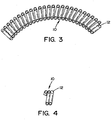
- Figs. 1-4 and 15 illustrate an arc shaped spring and Figs. 8-14 illustrate types of S-shaped springs ( Figs. 8-9 & 14 ), a C-shaped spring ( Figs. 10 & 13 ) a U-shaped spring ( Fig. 11 ) and a wave-shaped spring ( Fig. 12 ).
- the solid lines through the springs illustrated in Figs. 8-11 are merely is a line along the central axis of the spring to illustrate the shape of the spring and does not represent any type of structure of the spring.
- the spring in accordance with the present invention can have other shapes that include an arcuate shape.
- a conventionally coiled straight spring is formed by traditional helical spring manufacturing techniques. Such techniques include beginning with annealed or pre-hardened and tempered material of any required cross section. Current materials that can be used include, but are not limited to, 1070, 6150, modified 6150, and 9254 steels, as processed into suitable quality spring wire. Generally, round cross-section, pre-hardened and tempered (Rc 45-55) 6150 steel can be used. As can be appreciated, other materials can be used. As can also be appreciated, the material need not be annealed, pre-hardened and/or tempered. As can further be appreciated, the material can have different Rc values.
- the spring is then heat treated by an induction heating process.
- an induction heating process For example, in the case of pre-hardened and tempered 6150 steel, the heat treatment by induction heating would be less than about 1 minute and the metal would be heated to at least about 700F (370°C). Any standard induction heating process can be used.
- the fixture arrangement 20 includes a clamping arrangement having two arcuate profile surfaces 30, 40 that are positioned on opposite sides of the spring 10. As such, when the two arcuate profile surfaces of the clamping arrangement are drawn together while the straight spring is positioned between the two arcuate profile surfaces, the two arcuate profile surfaces upon contact with the sides of the spring will cause the spring to bend into the desired arcuate shape.
- the materials used to the form the two arcuate profile surfaces is non-limiting.
- the two arcuate profile surfaces can have an S-shape profile.
- the two arcuate profile surfaces can also have shapes for forming C-shaped spring (See Figs. 10 & 13 ), U-shaped springs (See Fig. 11 ), wave-shaped springs ( Fig. 12 ), etc.
- the radius of curvature of arcuate profile surface 40 that contacts a first side of the spring is greater than the radius of curvature of the arcuate profile surface 30 that contacts the opposite side of the spring.
- Arcuate profile surface 30 is illustrated as being mounted in a fixed position by mounts 32, 34; however, this is not required.
- Arcuate profile surface 40 is illustrated as being moveable by arms 42, 44 between a clamped and unclamped position; however, this is not required. As can be appreciated, either or both arcuate profile surfaces can be designed to be movable.
- the fixture can have other forms.
- the fixture can include the use of a close-fitting curved rod or pin of a different free angle and arc radius than the desired free angle and arc radius of the finished arcuate spring. This close-fitting curved rod or pin is inserted into the spring.
- other fixtures can be used to cause the spring to be bent into a desired arc prior to the heating process (e.g., bowed or curved tube, die, drum or mandrel about which the spring, etc.).
- the heated spring is quenched (e.g., air and/or liquid quench) to a temperature of about ⁇ 150°F (83°C) of ambient temperature, and typically about ⁇ 30°F (17°C) of ambient temperature in less than about 3 minutes, typically less than about 2 minutes, and more typically less than about 1 minute; however, other quench times can be used.
- the quench fluid is a liquid
- the liquid can be water at about ambient temperature; however, other water temperatures can be used.
- the quenching process generally occurs within about 120 seconds (e.g., ⁇ 60 seconds; ⁇ 30 seconds, etc.) after the spring is formed in the fixture and/or after induction heating process has been completed.
- the water when used, can include a soluble oil and/or other type of polymer material; however, this is not required.
- the spring is removed from the fixture (e.g., the two arcuate profile surfaces are again separated from one another, rod removed, etc.), at which time the spring retains an arcuate configuration, free or substantially of any internal stresses which would tend to straighten the spring.
- the step of induction heating is less than about 5 minutes (e.g., 0.1-3 minutes, 0.1-2 minutes, 0.1-1 minute, etc.)
- the step of bending the heated spring in the fixture is completed in less than about 5 minutes (e.g., 0.01-2 minutes, 0.01-1 minutes, 0.01-0.5 minute, etc.) after the step of induction heating
- the step of quenching the heated spring is completed in less than about 5 minutes (e.g., 0.1-3 minutes, 0.1-2 minutes, 0.1-1 minute, etc.) after the bending said heated spring in said fixture.
- the end cap includes a base portion 70 and a nose 60.
- the nose is designed to be at least partially inserted into the interior of the spring coils.
- the base portion has a generally circular cross-sectional shape; however, the base portion can have other shapes.
- the cross-section size and shape of the base portion is generally selected such that the base portion cannot be fully inserted into the interior of the spring coils; however, this is not required.
- the thickness of the base portion is non-limiting.
- the nose portion 60 is illustrated as having a non-uniform cross-sectional size; however, this is not required.
- the nose portion is illustrated has having a generally circular cross-sectional shape; however, the nose portion can have other shapes.
- the nose portion has an upper nose portion 62 and a lower nose portion 64; however, this is not required.
- the top section of the upper nose portion can optionally include a taper 61.
- the upper nose portion 62 is illustrated as having a smaller cross-sectional size than lower nose portion 64.
- Generally lower nose portion 64 has a cross-section size and shape such that the lower nose portion 64 engages the inner surfaces of the interior of the spring coils so as to facilitate in secure the end cap to the spring; however, this is not required.
- a transition 65 can optionally be formed between the upper nose portion 62 and a lower nose portion 64.
- the transition when used, can optionally have a tapered or sloped form.
- the upper surface of the base portion optionally includes a threading lip 72 and/or a stop 68.
- the threading lip when used, can have a narrow front portion as illustrated in FIG. 7 which is designed to engage the inner surfaces of the interior of the spring coils so that the end cap can be threaded into the spring; however, this is not required.
- the stop when used, is designed to limit the further threading of the end cap onto the spring. As the end cap is threaded onto the spring, the end 12 of the spring will engage the stop and thereby prevent further threading of the end cap into the spring.
- the threading lip is illustrated as increasing in thickness from the narrow front portion to the stop 68 as illustrated in FIG. 6 .
- the end cap can be formed of any type of material. The end cap, when used, can be used to extend the life of the spring by protecting the ends of the spring. When the ends of the spring are not properly ground, undesired stresses can be applied to the spring ends during use of the spring, thereby cause premature failure of the spring. The use of the end caps on the spring can reduce or eliminate such undesired stresses on the ends of the spring and therefore extend the usable life of the spring.
- One or more additional process steps can be used for form the arcuate spring of the present invention. Such optional additional steps include:
Landscapes
- Engineering & Computer Science (AREA)
- Chemical & Material Sciences (AREA)
- Mechanical Engineering (AREA)
- General Engineering & Computer Science (AREA)
- Physics & Mathematics (AREA)
- Organic Chemistry (AREA)
- Materials Engineering (AREA)
- Metallurgy (AREA)
- Crystallography & Structural Chemistry (AREA)
- Thermal Sciences (AREA)
- Acoustics & Sound (AREA)
- Aviation & Aerospace Engineering (AREA)
- Health & Medical Sciences (AREA)
- Child & Adolescent Psychology (AREA)
- Springs (AREA)
- Heat Treatment Of Articles (AREA)
- General Induction Heating (AREA)
Claims (13)
- Bogenförmige Feder (10), die eine Länge in einer Längsrichtung, mehrere Federwindungen und eine Mittelachse, die durch die mehreren Federwindungen hindurch verläuft, enthält, wobei die Feder so konfiguriert und bemessen ist, dass sie eine Bogenform bildet, wobei mindestens ein Abschnitt der Feder eine Bogenform, eine S-Form, eine C-Form, eine Wellenform oder eine U-Form enthält, wobei die Mittelachse entlang der Länge in Längsrichtung der Feder eine nicht-gerade Achse ist, während sich die Feder in ihrem freien Zustand befindet und im Wesentlichen frei von inneren Spannungen ist, wobei die Feder ein erstes und ein zweites Ende enthält, wobei das erste Ende eine Endkappe (50) enthält, die mit dem ersten Ende verbunden ist, wobei das zweite Ende eine Endkappe (50) enthält, die mit dem zweiten Ende verbunden ist, wobei jede der Endkappen (50) einen Basisabschnitt (70) und eine Nase (60) enthält, wobei die Nase (60) so konfiguriert ist, dass sie mindestens teilweise in ein Inneres der Federwindungen eingeführt werden kann, wobei der Basisabschnitt (70) eine solche Querschnittsgröße und Form aufweist, dass der Basisabschnitt (70) nicht vollständig in das Innere der Federwindungen (10) eingeführt werden kann, wobei die Nase (60) und der Basisabschnitt (70) der Endkappe (50) eine allgemein kreisförmige Querschnittsform aufweisen,
dadurch gekennzeichnet, dass die Nase (60) eine ungleichmäßige Querschnittsgröße entlang einer Länge in Längsrichtung der Nase (60) hat, wobei die Nase (60) einen oberen Nasenabschnitt (62) hat, der eine kleinere Querschnittsgröße hat als ein unterer Nasenabschnitt (64), wobei der untere Nasenabschnitt (64) näher an dem Basisabschnitt (70) positioniert ist als der obere Nasenabschnitt (62), wobei der untere Nasenabschnitt (64) mit dem oberen Nasenabschnitt (62) verbunden ist, wobei der obere Nasenabschnitt (62) eine kleinere Querschnittsfläche hat als eine Querschnittsfläche des unteren Nasenabschnitts (64), wobei die Oberseite des Basisabschnitts (70) eine Gewindelippe (72) und einen Endanschlag (68) enthält, wobei die Gewindelippe (72) so konfiguriert ist, dass sie die Innenfläche der Federwindungen in Eingriff nimmt, so dass die Endkappe (50) in die Feder (10) geschraubt werden kann, wobei der Endanschlag (68) so konfiguriert ist, dass er ein weiteres Aufschrauben der Endkappe (50) auf die Feder (10) begrenzt, wobei die Dicke der Gewindelippe (72) von dem schmalen vorderen Abschnitt bis zu dem Endanschlag (68) zunimmt. - Bogenförmige Feder nach Anspruch 1, wobei eine obere Region des oberen Nasenabschnitts (62) eine Verjüngung (61) enthält.
- Bogenförmige Feder nach Anspruch 1 oder 2, wobei ein schräger Übergang zwischen dem oberen Nasenabschnitt (62) und dem unteren Nasenabschnitt (64) vorhanden ist.
- Verfahren zum Bilden einer bogenförmigen Feder (10), die eine Länge in einer Längsrichtung, mehrere Federwindungen und eine Mittelachse, die durch die mehreren Federwindungen hindurch verläuft, aufweist, und das folgende Schritte umfasst:a. Wickeln eines Drahtes, um eine nicht-bogenförmige Feder zu bilden;b. Erwärmen der nicht-bogenförmigen Feder durch Induktionserwärmung vor dem Biegen der nicht-bogenförmigen Feder in einer Aufspannvorrichtung;c. Biegen der erwärmten Feder in der Aufspannvorrichtung; undd. Abschrecken der erwärmten Feder;
wobei die Feder so konfiguriert und bemessen ist, dass sie eine Bogenform bildet, wobei mindestens ein Abschnitt der Feder eine Bogenform, eine S-Form, eine C-Form, eine Wellenform oder eine U-Form enthält, wobei die Mittelachse entlang der Länge in Längsrichtung der Feder eine nicht-gerade Achse ist,
während sich die Feder in ihrem freien Zustand befindet und im Wesentlichen frei von inneren Spannungen ist, wobei die Feder ein erstes und ein zweites Ende enthält, wobei das erste Ende eine Endkappe (50) enthält, die mit dem ersten Ende verbunden ist, wobei das zweite Ende eine Endkappe (50) enthält, die mit dem zweiten Ende verbunden ist, wobei jede der Endkappen (50) einen Basisabschnitt (70) und eine Nase (60) enthält, wobei die Nase (60) so konfiguriert ist, dass sie mindestens teilweise in ein Inneres der Federwindungen eingeführt werden kann,
wobei der Basisabschnitt (70) eine solche Querschnittsgröße und Form aufweist, dass der Basisabschnitt (70) nicht vollständig in das Innere der Federwindungen (10) eingeführt werden kann, wobei die Nase (60) und der Basisabschnitt (70) der Endkappe (50) eine allgemein kreisförmige Querschnittsform aufweisen,
dadurch gekennzeichnet, dass die Nase (60) eine ungleichmäßige Querschnittsgröße entlang einer Länge in Längsrichtung der Nase (60) hat, wobei die Nase (60) einen oberen Nasenabschnitt (62) hat, der eine kleinere Querschnittsgröße hat als ein unterer Nasenabschnitt (64), wobei der untere Nasenabschnitt (64) näher an dem Basisabschnitt (70) positioniert ist als der obere Nasenabschnitt (62), wobei der untere Nasenabschnitt (64) mit dem oberen Nasenabschnitt (62) verbunden ist, wobei der obere Nasenabschnitt (62) eine kleinere Querschnittsfläche hat als eine Querschnittsfläche des unteren Nasenabschnitts (64), wobei die Oberseite des Basisabschnitts (70) eine Gewindelippe (72) und einen Endanschlag (68) enthält, wobei die Gewindelippe (72) so konfiguriert ist, dass sie die Innenfläche der Federwindungen in Eingriff nimmt, so dass die Endkappe (50) in die Feder (10) geschraubt werden kann, wobei der Endanschlag (68) so konfiguriert ist, dass er ein weiteres Aufschrauben der Endkappe (50) auf die Feder (10) begrenzt, wobei die Dicke der Gewindelippe (72) von dem schmalen vorderen Abschnitt bis zu dem Endanschlag (68) zunimmt. - Verfahren nach Anspruch 4, das den Schritt des Entfernens der abgeschreckten Feder aus der Aufspannvorrichtung nach dem Abschreckungsschritt enthält.
- Verfahren nach Anspruch 4, wobei der Schritt der Induktionserwärmung weniger als etwa 5 Minuten dauert, der Schritt des Biegens der erwärmten Feder in der Aufspannvorrichtung in weniger als etwa 5 Minuten nach dem Schritt der Induktionserwärmung abgeschlossen ist, und der Schritt des Abschreckens der erwärmten Feder in weniger als etwa 5 Minuten nach dem Biegen der erwärmten Feder in der Aufspannvorrichtung abgeschlossen ist.
- Verfahren nach Anspruch 5, wobei der Schritt der Induktionserwärmung weniger als etwa 5 Minuten dauert, der Schritt des Biegens der erwärmten Feder in der Aufspannvorrichtung in weniger als etwa 5 Minuten nach dem Schritt der Induktionserwärmung abgeschlossen ist, und der Schritt des Abschreckens der erwärmten Feder in weniger als etwa 5 Minuten nach dem Biegen der erwärmten Feder in der Aufspannvorrichtung abgeschlossen ist.
- Verfahren nach Anspruch 4, wobei die Aufspannvorrichtung eine Klemmanordnung enthält, die zwei bogenförmige Profilflächen aufweist, wobei mindestens eine der bogenförmigen Profilflächen so gestaltet ist, dass sie zwischen einer festgeklemmten und einer ungedämpften Position beweglich ist.
- Verfahren nach einem der Ansprüche 5-7, wobei die Aufspannvorrichtung eine Klemmanordnung enthält, die zwei bogenförmige Profilflächen aufweist, wobei mindestens eine der bogenförmigen Profilflächen so gestaltet ist, dass sie zwischen einer festgeklemmten und einer ungedämpften Position beweglich ist.
- Verfahren nach Anspruch 4, das den Schritt des Anbringens einer Endkappe an mindestens einem Ende der Feder nach dem Schritt des Abschreckens enthält, wobei die Endkappe einen Basisabschnitt und eine Nase enthält, wobei die Nase so gestaltet ist, dass sie mindestens teilweise in ein Inneres der Windungen der Federwindungen eingeführt werden kann, wobei Querschnittsgröße und Form des Basisabschnitts so gewählt sind, dass der Basisabschnitt nicht vollständig in das Innere der Federwindungen eingeführt werden kann.
- Verfahren nach einem der Ansprüche 5-9, das den Schritt des Anbringens einer Endkappe an mindestens einem Ende der Feder nach dem Schritt des Abschreckens enthält, wobei die Endkappe einen Basisabschnitt und eine Nase enthält, wobei die Nase so gestaltet ist, dass sie mindestens teilweise in ein Inneres der Windungen der Federwindungen eingeführt werden kann, wobei Querschnittsgröße und Form des Basisabschnitts so gewählt sind, dass der Basisabschnitt nicht vollständig in das Innere der Federwindungen eingeführt werden kann.
- Verfahren nach Anspruch 10, wobei die Oberseite des Basisabschnitts eine Gewindelippe und einen Endanschlag enthält, wobei die Gewindelippe so gestaltet ist, dass sie die Innenfläche der Federwindungen in Eingriff nimmt, so dass die Endkappe in die Feder eingeschraubt werden kann, wobei der Endanschlag so gestaltet ist, dass er ein weiteres Aufschrauben der Endkappe auf die Feder begrenzt.
- Verfahren nach Anspruch 11, wobei die Oberseite des Basisabschnitts eine Gewindelippe und einen Endanschlag enthält, wobei die Gewindelippe so gestaltet ist, dass sie die Innenfläche der Federwindungen in Eingriff nimmt, so dass die Endkappe in die Feder eingeschraubt werden kann, wobei der Endanschlag so gestaltet ist, dass er ein weiteres Aufschrauben der Endkappe auf die Feder begrenzt.
Priority Applications (2)
| Application Number | Priority Date | Filing Date | Title |
|---|---|---|---|
| PL13813068T PL2869950T3 (pl) | 2012-07-06 | 2013-07-05 | Sprężyna łukowa o wysokiej wytrzymałości zmęczeniowej |
| EP20151796.8A EP3680039A1 (de) | 2012-07-06 | 2013-07-05 | Gebogene feder mit hoher ermüdungsbeständigkeit |
Applications Claiming Priority (2)
| Application Number | Priority Date | Filing Date | Title |
|---|---|---|---|
| US201261668658P | 2012-07-06 | 2012-07-06 | |
| PCT/US2013/049439 WO2014008466A2 (en) | 2012-07-06 | 2013-07-05 | High fatigue arcuate spring |
Related Child Applications (2)
| Application Number | Title | Priority Date | Filing Date |
|---|---|---|---|
| EP20151796.8A Division EP3680039A1 (de) | 2012-07-06 | 2013-07-05 | Gebogene feder mit hoher ermüdungsbeständigkeit |
| EP20151796.8A Division-Into EP3680039A1 (de) | 2012-07-06 | 2013-07-05 | Gebogene feder mit hoher ermüdungsbeständigkeit |
Publications (3)
| Publication Number | Publication Date |
|---|---|
| EP2869950A2 EP2869950A2 (de) | 2015-05-13 |
| EP2869950A4 EP2869950A4 (de) | 2016-09-07 |
| EP2869950B1 true EP2869950B1 (de) | 2020-06-17 |
Family
ID=49882626
Family Applications (2)
| Application Number | Title | Priority Date | Filing Date |
|---|---|---|---|
| EP13813068.7A Active EP2869950B1 (de) | 2012-07-06 | 2013-07-05 | Gebogene feder mit hoher ermüdungsbeständigkeit |
| EP20151796.8A Withdrawn EP3680039A1 (de) | 2012-07-06 | 2013-07-05 | Gebogene feder mit hoher ermüdungsbeständigkeit |
Family Applications After (1)
| Application Number | Title | Priority Date | Filing Date |
|---|---|---|---|
| EP20151796.8A Withdrawn EP3680039A1 (de) | 2012-07-06 | 2013-07-05 | Gebogene feder mit hoher ermüdungsbeständigkeit |
Country Status (9)
| Country | Link |
|---|---|
| US (1) | US10508700B2 (de) |
| EP (2) | EP2869950B1 (de) |
| JP (1) | JP6469005B2 (de) |
| KR (1) | KR102011176B1 (de) |
| CN (1) | CN104704257B (de) |
| BR (1) | BR112015000087B1 (de) |
| MX (2) | MX372897B (de) |
| PL (1) | PL2869950T3 (de) |
| WO (1) | WO2014008466A2 (de) |
Families Citing this family (9)
| Publication number | Priority date | Publication date | Assignee | Title |
|---|---|---|---|---|
| CN104190829B (zh) * | 2014-08-13 | 2016-06-08 | 曲阜天博汽车电器有限公司 | 弧形弹簧的制作工艺 |
| US9379104B1 (en) * | 2015-03-05 | 2016-06-28 | Globalfoundries Inc. | Method to make gate-to-body contact to release plasma induced charging |
| WO2019036801A1 (en) | 2017-08-24 | 2019-02-28 | Ressorts Liberte Inc. | HELICAL SPRING AND METHOD FOR MANUFACTURING THE SAME |
| CN109909406B (zh) * | 2019-04-19 | 2024-05-03 | 无锡威孚精密机械制造有限责任公司 | 一种弧形弹簧热定型机 |
| DE102019210161A1 (de) * | 2019-07-10 | 2021-01-14 | Zf Friedrichshafen Ag | Torsionsschwingungsdämpfer mit Federteller und Federteller für einen Torsionsschwingungsdämpfer |
| CN112024790B (zh) * | 2019-11-26 | 2022-05-10 | 苏州市新艺弹簧厂 | 一种弯管弹簧的弯曲装置 |
| CN111014524B (zh) * | 2019-12-18 | 2022-04-26 | 安庆谢德尔汽车零部件有限公司 | 一种高应力弹簧制造工艺 |
| CN115315323B (zh) * | 2020-03-25 | 2023-09-19 | 日本发条株式会社 | 弧形弹簧的制造方法及装置 |
| CN116921590B (zh) * | 2023-09-18 | 2023-12-01 | 毕克礼斯精密部件(太仓)有限公司 | 一种弧形弹簧穿套式夹具 |
Family Cites Families (25)
| Publication number | Priority date | Publication date | Assignee | Title |
|---|---|---|---|---|
| US2466094A (en) * | 1946-03-23 | 1949-04-05 | Frost Railway Supply Co | Railway car spring |
| US4193824A (en) * | 1976-08-18 | 1980-03-18 | Egorov Viktor P | Method for manufacturing steel spring leaves |
| NO145110C (no) * | 1979-02-16 | 1982-01-20 | Kongsberg Vapenfab As | Stoetdemper til opplagring av oemfintlig utstyr. |
| DE3529816A1 (de) * | 1984-08-21 | 1986-03-06 | Aisin Seiki K.K., Kariya, Aichi | Vorrichtung zur absorption einer drehmomentaenderung |
| JP2718413B2 (ja) | 1986-07-05 | 1998-02-25 | ルーク・ラメレン・ウント・クツプルングスバウ・ゲゼルシヤフト・ミツト・ベシユレンクテル・ハフツング | 振動緩衝装置 |
| US4891033A (en) * | 1988-04-20 | 1990-01-02 | Automatic Spring Coiling Co. | Device for coupling coil springs compressed in series in a clutch damper |
| FR2641048B1 (de) * | 1988-12-28 | 1991-03-08 | Valeo | |
| FR2652399B1 (fr) * | 1989-09-26 | 1994-06-24 | Valeo | Dispositif amortisseur de torsion a patins de frottement, notamment pour vehicule automobile. |
| US5052664A (en) * | 1989-11-01 | 1991-10-01 | Barnes Group Inc. | Arcuate spring |
| CN2091991U (zh) * | 1990-12-15 | 1992-01-01 | 陆锺 | 端圈动态不并圈的螺旋压缩弹簧 |
| DE4224951C1 (de) * | 1992-07-29 | 1993-11-04 | Krupp Ag Hoesch Krupp | Verfahren und vorrichtung zum herstellen von gekruemmten schraubenfedern |
| JPH1182582A (ja) * | 1997-09-08 | 1999-03-26 | Exedy Corp | ロックアップダンパー用コイルスプリング組立体 |
| BR9904885A (pt) * | 1998-03-25 | 2000-12-19 | Luk Lamellen & Kupplungsbau | Amortecedor de vibrações de torção |
| JP2000129359A (ja) * | 1998-10-19 | 2000-05-09 | Suncall Corp | クラッチディスク用アーク状スプリング製造方法 |
| JP3848508B2 (ja) * | 1999-07-19 | 2006-11-22 | 株式会社エクセディ | ダンパー機構 |
| DE19943629B4 (de) * | 1999-09-11 | 2015-04-09 | Andreas Stihl Ag & Co. | Handgeführtes Arbeitsgerät |
| DE10105826B4 (de) * | 2001-02-07 | 2012-05-31 | Andreas Stihl Ag & Co | Schwingungsdämpfer zwischen zwei Bauteilen |
| JP3904849B2 (ja) * | 2001-06-13 | 2007-04-11 | 株式会社エクセディ | ダンパー機構 |
| DE10334906B4 (de) * | 2002-07-30 | 2018-11-15 | Andreas Stihl Ag & Co. Kg | Antivibrationselement |
| WO2006129710A1 (ja) * | 2005-05-31 | 2006-12-07 | Nhk Spring Co., Ltd. | コイルばね |
| JP5014660B2 (ja) * | 2006-03-31 | 2012-08-29 | 村田発條株式会社 | アーク状コイルスプリングの製造方法 |
| DE102009022440B4 (de) | 2009-05-23 | 2019-09-12 | Borgwarner Inc. | Drehschwingungsdämpfer mit mindestens einer Federeinrichtung aus zwei Schraubenfedern |
| JP5393280B2 (ja) * | 2009-06-17 | 2014-01-22 | 日本発條株式会社 | 車両懸架用コイルばねと、その製造方法 |
| JP5865246B2 (ja) * | 2010-07-26 | 2016-02-17 | 中央発條株式会社 | ばねの製造方法及び通電加熱装置 |
| CN102424908A (zh) * | 2011-11-24 | 2012-04-25 | 上海力睿精密金属有限公司 | 弹簧线生产方法 |
-
2013
- 2013-07-05 EP EP13813068.7A patent/EP2869950B1/de active Active
- 2013-07-05 PL PL13813068T patent/PL2869950T3/pl unknown
- 2013-07-05 EP EP20151796.8A patent/EP3680039A1/de not_active Withdrawn
- 2013-07-05 MX MX2015000172A patent/MX372897B/es active IP Right Grant
- 2013-07-05 JP JP2015520706A patent/JP6469005B2/ja active Active
- 2013-07-05 KR KR1020157003264A patent/KR102011176B1/ko not_active Expired - Fee Related
- 2013-07-05 US US13/935,795 patent/US10508700B2/en active Active
- 2013-07-05 MX MX2020001444A patent/MX385225B/es unknown
- 2013-07-05 BR BR112015000087-8A patent/BR112015000087B1/pt not_active IP Right Cessation
- 2013-07-05 CN CN201380036173.2A patent/CN104704257B/zh not_active Expired - Fee Related
- 2013-07-05 WO PCT/US2013/049439 patent/WO2014008466A2/en not_active Ceased
Non-Patent Citations (1)
| Title |
|---|
| None * |
Also Published As
| Publication number | Publication date |
|---|---|
| CN104704257A (zh) | 2015-06-10 |
| MX2015000172A (es) | 2015-08-12 |
| MX372897B (es) | 2020-04-27 |
| US20140015179A1 (en) | 2014-01-16 |
| EP2869950A4 (de) | 2016-09-07 |
| BR112015000087A2 (pt) | 2019-10-01 |
| PL2869950T3 (pl) | 2020-11-30 |
| MX385225B (es) | 2025-03-14 |
| EP3680039A1 (de) | 2020-07-15 |
| MX2020001444A (es) | 2021-06-29 |
| KR102011176B1 (ko) | 2019-08-14 |
| US10508700B2 (en) | 2019-12-17 |
| KR20150029018A (ko) | 2015-03-17 |
| WO2014008466A2 (en) | 2014-01-09 |
| WO2014008466A3 (en) | 2014-02-27 |
| CN104704257B (zh) | 2017-04-19 |
| JP2015523515A (ja) | 2015-08-13 |
| EP2869950A2 (de) | 2015-05-13 |
| BR112015000087B1 (pt) | 2022-01-25 |
| JP6469005B2 (ja) | 2019-02-13 |
Similar Documents
| Publication | Publication Date | Title |
|---|---|---|
| EP2869950B1 (de) | Gebogene feder mit hoher ermüdungsbeständigkeit | |
| US6544360B1 (en) | Highly strengthened spring and process for producing the same | |
| US5052664A (en) | Arcuate spring | |
| US9752636B2 (en) | Helical compression spring and method for manufacturing same | |
| EP2743366B1 (de) | Kompressionsspulenfeder und herstellungsverfahren dafür | |
| RU2462519C1 (ru) | Способ упрочнения цилиндрических винтовых пружин | |
| CA2981220C (en) | Coil spring | |
| DE102014214592B4 (de) | Schraubenfeder aus Federstahl und Verfahren zur Herstellung einer Schraubenfeder | |
| EP3438495B1 (de) | Hohles federelement | |
| JP2019124363A (ja) | コイルスプリングの製造方法 | |
| US6811149B1 (en) | Fatigue and damage tolerant coil spring | |
| KR102494200B1 (ko) | 코일스프링 성형용 조립식 아버 | |
| RU2478016C1 (ru) | Способ изготовления цилиндрических винтовых пружин | |
| Scuracchio et al. | Residual stresses induced by shot peening and fatigue durability of leaf springs | |
| Mahajan et al. | Failure analysis of tension spring | |
| Bock et al. | Lightweight leaf springs | |
| KR101467041B1 (ko) | 크랭크 샤프트 제조방법 |
Legal Events
| Date | Code | Title | Description |
|---|---|---|---|
| PUAI | Public reference made under article 153(3) epc to a published international application that has entered the european phase |
Free format text: ORIGINAL CODE: 0009012 |
|
| 17P | Request for examination filed |
Effective date: 20150206 |
|
| AK | Designated contracting states |
Kind code of ref document: A2 Designated state(s): AL AT BE BG CH CY CZ DE DK EE ES FI FR GB GR HR HU IE IS IT LI LT LU LV MC MK MT NL NO PL PT RO RS SE SI SK SM TR |
|
| AX | Request for extension of the european patent |
Extension state: BA ME |
|
| DAX | Request for extension of the european patent (deleted) | ||
| RIC1 | Information provided on ipc code assigned before grant |
Ipc: F16F 15/123 20060101ALI20160520BHEP Ipc: F16F 1/12 20060101ALI20160520BHEP Ipc: B21F 35/00 20060101AFI20160520BHEP |
|
| A4 | Supplementary search report drawn up and despatched |
Effective date: 20160805 |
|
| RIC1 | Information provided on ipc code assigned before grant |
Ipc: F16F 1/12 20060101ALI20160801BHEP Ipc: F16F 15/123 20060101ALI20160801BHEP Ipc: B21F 35/00 20060101AFI20160801BHEP |
|
| STAA | Information on the status of an ep patent application or granted ep patent |
Free format text: STATUS: EXAMINATION IS IN PROGRESS |
|
| 17Q | First examination report despatched |
Effective date: 20180313 |
|
| GRAP | Despatch of communication of intention to grant a patent |
Free format text: ORIGINAL CODE: EPIDOSNIGR1 |
|
| STAA | Information on the status of an ep patent application or granted ep patent |
Free format text: STATUS: GRANT OF PATENT IS INTENDED |
|
| INTG | Intention to grant announced |
Effective date: 20200103 |
|
| GRAS | Grant fee paid |
Free format text: ORIGINAL CODE: EPIDOSNIGR3 |
|
| GRAA | (expected) grant |
Free format text: ORIGINAL CODE: 0009210 |
|
| STAA | Information on the status of an ep patent application or granted ep patent |
Free format text: STATUS: THE PATENT HAS BEEN GRANTED |
|
| AK | Designated contracting states |
Kind code of ref document: B1 Designated state(s): AL AT BE BG CH CY CZ DE DK EE ES FI FR GB GR HR HU IE IS IT LI LT LU LV MC MK MT NL NO PL PT RO RS SE SI SK SM TR |
|
| REG | Reference to a national code |
Ref country code: GB Ref legal event code: FG4D |
|
| REG | Reference to a national code |
Ref country code: CH Ref legal event code: EP |
|
| REG | Reference to a national code |
Ref country code: IE Ref legal event code: FG4D |
|
| REG | Reference to a national code |
Ref country code: DE Ref legal event code: R096 Ref document number: 602013069984 Country of ref document: DE |
|
| REG | Reference to a national code |
Ref country code: AT Ref legal event code: REF Ref document number: 1280694 Country of ref document: AT Kind code of ref document: T Effective date: 20200715 |
|
| PG25 | Lapsed in a contracting state [announced via postgrant information from national office to epo] |
Ref country code: NO Free format text: LAPSE BECAUSE OF FAILURE TO SUBMIT A TRANSLATION OF THE DESCRIPTION OR TO PAY THE FEE WITHIN THE PRESCRIBED TIME-LIMIT Effective date: 20200917 Ref country code: GR Free format text: LAPSE BECAUSE OF FAILURE TO SUBMIT A TRANSLATION OF THE DESCRIPTION OR TO PAY THE FEE WITHIN THE PRESCRIBED TIME-LIMIT Effective date: 20200918 Ref country code: SE Free format text: LAPSE BECAUSE OF FAILURE TO SUBMIT A TRANSLATION OF THE DESCRIPTION OR TO PAY THE FEE WITHIN THE PRESCRIBED TIME-LIMIT Effective date: 20200617 Ref country code: FI Free format text: LAPSE BECAUSE OF FAILURE TO SUBMIT A TRANSLATION OF THE DESCRIPTION OR TO PAY THE FEE WITHIN THE PRESCRIBED TIME-LIMIT Effective date: 20200617 Ref country code: LT Free format text: LAPSE BECAUSE OF FAILURE TO SUBMIT A TRANSLATION OF THE DESCRIPTION OR TO PAY THE FEE WITHIN THE PRESCRIBED TIME-LIMIT Effective date: 20200617 |
|
| REG | Reference to a national code |
Ref country code: LT Ref legal event code: MG4D |
|
| REG | Reference to a national code |
Ref country code: NL Ref legal event code: MP Effective date: 20200617 |
|
| PG25 | Lapsed in a contracting state [announced via postgrant information from national office to epo] |
Ref country code: HR Free format text: LAPSE BECAUSE OF FAILURE TO SUBMIT A TRANSLATION OF THE DESCRIPTION OR TO PAY THE FEE WITHIN THE PRESCRIBED TIME-LIMIT Effective date: 20200617 Ref country code: BG Free format text: LAPSE BECAUSE OF FAILURE TO SUBMIT A TRANSLATION OF THE DESCRIPTION OR TO PAY THE FEE WITHIN THE PRESCRIBED TIME-LIMIT Effective date: 20200917 Ref country code: LV Free format text: LAPSE BECAUSE OF FAILURE TO SUBMIT A TRANSLATION OF THE DESCRIPTION OR TO PAY THE FEE WITHIN THE PRESCRIBED TIME-LIMIT Effective date: 20200617 Ref country code: RS Free format text: LAPSE BECAUSE OF FAILURE TO SUBMIT A TRANSLATION OF THE DESCRIPTION OR TO PAY THE FEE WITHIN THE PRESCRIBED TIME-LIMIT Effective date: 20200617 |
|
| REG | Reference to a national code |
Ref country code: AT Ref legal event code: MK05 Ref document number: 1280694 Country of ref document: AT Kind code of ref document: T Effective date: 20200617 |
|
| PG25 | Lapsed in a contracting state [announced via postgrant information from national office to epo] |
Ref country code: NL Free format text: LAPSE BECAUSE OF FAILURE TO SUBMIT A TRANSLATION OF THE DESCRIPTION OR TO PAY THE FEE WITHIN THE PRESCRIBED TIME-LIMIT Effective date: 20200617 Ref country code: AL Free format text: LAPSE BECAUSE OF FAILURE TO SUBMIT A TRANSLATION OF THE DESCRIPTION OR TO PAY THE FEE WITHIN THE PRESCRIBED TIME-LIMIT Effective date: 20200617 |
|
| PG25 | Lapsed in a contracting state [announced via postgrant information from national office to epo] |
Ref country code: ES Free format text: LAPSE BECAUSE OF FAILURE TO SUBMIT A TRANSLATION OF THE DESCRIPTION OR TO PAY THE FEE WITHIN THE PRESCRIBED TIME-LIMIT Effective date: 20200617 Ref country code: PT Free format text: LAPSE BECAUSE OF FAILURE TO SUBMIT A TRANSLATION OF THE DESCRIPTION OR TO PAY THE FEE WITHIN THE PRESCRIBED TIME-LIMIT Effective date: 20201019 Ref country code: AT Free format text: LAPSE BECAUSE OF FAILURE TO SUBMIT A TRANSLATION OF THE DESCRIPTION OR TO PAY THE FEE WITHIN THE PRESCRIBED TIME-LIMIT Effective date: 20200617 Ref country code: SM Free format text: LAPSE BECAUSE OF FAILURE TO SUBMIT A TRANSLATION OF THE DESCRIPTION OR TO PAY THE FEE WITHIN THE PRESCRIBED TIME-LIMIT Effective date: 20200617 Ref country code: RO Free format text: LAPSE BECAUSE OF FAILURE TO SUBMIT A TRANSLATION OF THE DESCRIPTION OR TO PAY THE FEE WITHIN THE PRESCRIBED TIME-LIMIT Effective date: 20200617 Ref country code: EE Free format text: LAPSE BECAUSE OF FAILURE TO SUBMIT A TRANSLATION OF THE DESCRIPTION OR TO PAY THE FEE WITHIN THE PRESCRIBED TIME-LIMIT Effective date: 20200617 Ref country code: CZ Free format text: LAPSE BECAUSE OF FAILURE TO SUBMIT A TRANSLATION OF THE DESCRIPTION OR TO PAY THE FEE WITHIN THE PRESCRIBED TIME-LIMIT Effective date: 20200617 |
|
| PG25 | Lapsed in a contracting state [announced via postgrant information from national office to epo] |
Ref country code: SK Free format text: LAPSE BECAUSE OF FAILURE TO SUBMIT A TRANSLATION OF THE DESCRIPTION OR TO PAY THE FEE WITHIN THE PRESCRIBED TIME-LIMIT Effective date: 20200617 Ref country code: IS Free format text: LAPSE BECAUSE OF FAILURE TO SUBMIT A TRANSLATION OF THE DESCRIPTION OR TO PAY THE FEE WITHIN THE PRESCRIBED TIME-LIMIT Effective date: 20201017 |
|
| REG | Reference to a national code |
Ref country code: CH Ref legal event code: PL |
|
| REG | Reference to a national code |
Ref country code: DE Ref legal event code: R097 Ref document number: 602013069984 Country of ref document: DE |
|
| PG25 | Lapsed in a contracting state [announced via postgrant information from national office to epo] |
Ref country code: MC Free format text: LAPSE BECAUSE OF FAILURE TO SUBMIT A TRANSLATION OF THE DESCRIPTION OR TO PAY THE FEE WITHIN THE PRESCRIBED TIME-LIMIT Effective date: 20200617 |
|
| PLBE | No opposition filed within time limit |
Free format text: ORIGINAL CODE: 0009261 |
|
| STAA | Information on the status of an ep patent application or granted ep patent |
Free format text: STATUS: NO OPPOSITION FILED WITHIN TIME LIMIT |
|
| PG25 | Lapsed in a contracting state [announced via postgrant information from national office to epo] |
Ref country code: DK Free format text: LAPSE BECAUSE OF FAILURE TO SUBMIT A TRANSLATION OF THE DESCRIPTION OR TO PAY THE FEE WITHIN THE PRESCRIBED TIME-LIMIT Effective date: 20200617 Ref country code: CH Free format text: LAPSE BECAUSE OF NON-PAYMENT OF DUE FEES Effective date: 20200731 Ref country code: LI Free format text: LAPSE BECAUSE OF NON-PAYMENT OF DUE FEES Effective date: 20200731 Ref country code: IE Free format text: LAPSE BECAUSE OF NON-PAYMENT OF DUE FEES Effective date: 20200705 Ref country code: LU Free format text: LAPSE BECAUSE OF NON-PAYMENT OF DUE FEES Effective date: 20200705 |
|
| 26N | No opposition filed |
Effective date: 20210318 |
|
| GBPC | Gb: european patent ceased through non-payment of renewal fee |
Effective date: 20200917 |
|
| PG25 | Lapsed in a contracting state [announced via postgrant information from national office to epo] |
Ref country code: SI Free format text: LAPSE BECAUSE OF FAILURE TO SUBMIT A TRANSLATION OF THE DESCRIPTION OR TO PAY THE FEE WITHIN THE PRESCRIBED TIME-LIMIT Effective date: 20200617 |
|
| PG25 | Lapsed in a contracting state [announced via postgrant information from national office to epo] |
Ref country code: GB Free format text: LAPSE BECAUSE OF NON-PAYMENT OF DUE FEES Effective date: 20200917 |
|
| PGFP | Annual fee paid to national office [announced via postgrant information from national office to epo] |
Ref country code: IT Payment date: 20210709 Year of fee payment: 9 Ref country code: FR Payment date: 20210708 Year of fee payment: 9 |
|
| PGFP | Annual fee paid to national office [announced via postgrant information from national office to epo] |
Ref country code: BE Payment date: 20210706 Year of fee payment: 9 Ref country code: PL Payment date: 20210705 Year of fee payment: 9 Ref country code: DE Payment date: 20210709 Year of fee payment: 9 |
|
| PG25 | Lapsed in a contracting state [announced via postgrant information from national office to epo] |
Ref country code: TR Free format text: LAPSE BECAUSE OF FAILURE TO SUBMIT A TRANSLATION OF THE DESCRIPTION OR TO PAY THE FEE WITHIN THE PRESCRIBED TIME-LIMIT Effective date: 20200617 Ref country code: MT Free format text: LAPSE BECAUSE OF FAILURE TO SUBMIT A TRANSLATION OF THE DESCRIPTION OR TO PAY THE FEE WITHIN THE PRESCRIBED TIME-LIMIT Effective date: 20200617 Ref country code: CY Free format text: LAPSE BECAUSE OF FAILURE TO SUBMIT A TRANSLATION OF THE DESCRIPTION OR TO PAY THE FEE WITHIN THE PRESCRIBED TIME-LIMIT Effective date: 20200617 |
|
| PG25 | Lapsed in a contracting state [announced via postgrant information from national office to epo] |
Ref country code: MK Free format text: LAPSE BECAUSE OF FAILURE TO SUBMIT A TRANSLATION OF THE DESCRIPTION OR TO PAY THE FEE WITHIN THE PRESCRIBED TIME-LIMIT Effective date: 20200617 |
|
| REG | Reference to a national code |
Ref country code: DE Ref legal event code: R119 Ref document number: 602013069984 Country of ref document: DE |
|
| REG | Reference to a national code |
Ref country code: BE Ref legal event code: MM Effective date: 20220731 |
|
| PG25 | Lapsed in a contracting state [announced via postgrant information from national office to epo] |
Ref country code: FR Free format text: LAPSE BECAUSE OF NON-PAYMENT OF DUE FEES Effective date: 20220731 |
|
| PG25 | Lapsed in a contracting state [announced via postgrant information from national office to epo] |
Ref country code: DE Free format text: LAPSE BECAUSE OF NON-PAYMENT OF DUE FEES Effective date: 20230201 Ref country code: BE Free format text: LAPSE BECAUSE OF NON-PAYMENT OF DUE FEES Effective date: 20220731 |
|
| PG25 | Lapsed in a contracting state [announced via postgrant information from national office to epo] |
Ref country code: IT Free format text: LAPSE BECAUSE OF NON-PAYMENT OF DUE FEES Effective date: 20220705 |
|
| PG25 | Lapsed in a contracting state [announced via postgrant information from national office to epo] |
Ref country code: PL Free format text: LAPSE BECAUSE OF NON-PAYMENT OF DUE FEES Effective date: 20220705 |