EP2869686B1 - Niedrigprofil-saatgutspender mit dosierungsfunktionalität - Google Patents
Niedrigprofil-saatgutspender mit dosierungsfunktionalität Download PDFInfo
- Publication number
- EP2869686B1 EP2869686B1 EP12880924.1A EP12880924A EP2869686B1 EP 2869686 B1 EP2869686 B1 EP 2869686B1 EP 12880924 A EP12880924 A EP 12880924A EP 2869686 B1 EP2869686 B1 EP 2869686B1
- Authority
- EP
- European Patent Office
- Prior art keywords
- seed
- conveyor
- housing
- cleats
- treatment
- Prior art date
- Legal status (The legal status is an assumption and is not a legal conclusion. Google has not performed a legal analysis and makes no representation as to the accuracy of the status listed.)
- Active
Links
Images


Classifications
-
- A—HUMAN NECESSITIES
- A01—AGRICULTURE; FORESTRY; ANIMAL HUSBANDRY; HUNTING; TRAPPING; FISHING
- A01C—PLANTING; SOWING; FERTILISING
- A01C1/00—Apparatus, or methods of use thereof, for testing or treating seed, roots, or the like, prior to sowing or planting
- A01C1/06—Coating or dressing seed
-
- A—HUMAN NECESSITIES
- A01—AGRICULTURE; FORESTRY; ANIMAL HUSBANDRY; HUNTING; TRAPPING; FISHING
- A01C—PLANTING; SOWING; FERTILISING
- A01C1/00—Apparatus, or methods of use thereof, for testing or treating seed, roots, or the like, prior to sowing or planting
-
- B—PERFORMING OPERATIONS; TRANSPORTING
- B65—CONVEYING; PACKING; STORING; HANDLING THIN OR FILAMENTARY MATERIAL
- B65G—TRANSPORT OR STORAGE DEVICES, e.g. CONVEYORS FOR LOADING OR TIPPING, SHOP CONVEYOR SYSTEMS OR PNEUMATIC TUBE CONVEYORS
- B65G15/00—Conveyors having endless load-conveying surfaces, i.e. belts and like continuous members, to which tractive effort is transmitted by means other than endless driving elements of similar configuration
- B65G15/30—Belts or like endless load-carriers
- B65G15/32—Belts or like endless load-carriers made of rubber or plastics
- B65G15/42—Belts or like endless load-carriers made of rubber or plastics having ribs, ridges, or other surface projections
- B65G15/44—Belts or like endless load-carriers made of rubber or plastics having ribs, ridges, or other surface projections for impelling the loads
-
- A—HUMAN NECESSITIES
- A01—AGRICULTURE; FORESTRY; ANIMAL HUSBANDRY; HUNTING; TRAPPING; FISHING
- A01C—PLANTING; SOWING; FERTILISING
- A01C15/00—Fertiliser distributors
- A01C15/003—Bulk fertiliser or grain handling in the field or on the farm
-
- B—PERFORMING OPERATIONS; TRANSPORTING
- B65—CONVEYING; PACKING; STORING; HANDLING THIN OR FILAMENTARY MATERIAL
- B65G—TRANSPORT OR STORAGE DEVICES, e.g. CONVEYORS FOR LOADING OR TIPPING, SHOP CONVEYOR SYSTEMS OR PNEUMATIC TUBE CONVEYORS
- B65G15/00—Conveyors having endless load-conveying surfaces, i.e. belts and like continuous members, to which tractive effort is transmitted by means other than endless driving elements of similar configuration
- B65G15/30—Belts or like endless load-carriers
- B65G15/32—Belts or like endless load-carriers made of rubber or plastics
- B65G15/42—Belts or like endless load-carriers made of rubber or plastics having ribs, ridges, or other surface projections
Definitions
- the present invention relates to a seed treatment apparatus, and more particularly to a seed treatment apparatus incorporating seed metering.
- treatments may include the application of fertilizers, insecticides, pesticides and fungicides, and normally take the form of liquid chemical that is sprayed onto the seed.
- seed treatment apparatuses are commercially available, it is more common to see a farmer spray treatment directly onto seed just before it is drawn up an auger, the auger being employed to mix the treated seed in an effort to spread the treatment coating over as much seed surface as possible before planting.
- the Graham apparatus or "G3" is used with two augers, where one auger transports seed upwardly (from an auger hopper positioned under a hopper-bottom bin or similar) toward the upper intake of the seed treater, and the seed is then sprayed with treatment as it falls downwardly through the seed treater, with the second auger serving to mix the treated seed and transport it upwardly to a truck or storage unit.
- the seed falls in an annular pattern adjacent the inner surface of the treater, and a centrally-disposed nozzle sprays treatment in a conical spray pattern in an effort to contact as much seed as possible.
- the present invention accordingly seeks to provide a seed treatment apparatus that meters seed based on volume and uses mass flow based on seed density to calculate optimal treatment application rate for a given seed type, in an apparatus configuration capable of use with on-farm storage units.
- the conveyor may be a continuous belt conveyor or a circular conveyor
- the seed treatment applicator may comprise a peristaltic pump and spray nozzles.
- the apparatus may further comprise a controller for controlling the conveyor drive mechanism and the seed treatment applicator, and the controller comprises a programmable logic controller, a data storage, a user interface, and a display (the user interface and the display may collectively be a touchscreen monitor).
- Certain embodiments may further comprise a channeling collar mounted on the conveyor intake for directing the seed toward the conveyor intake, and the channeling collar may also be upwardly biased so as to sealingly engage with a source of the seed.
- the housing may also be provided with an extensible support for selectively elevating the second end of the conveyor, thereby providing an enhanced area for treatment application, and further comprising at least one ground-engaging wheel to enable relocation of the apparatus.
- the apparatus may also comprises a programmable logic controller that is programmed to convert the seed volume flow to the seed mass flow using the determined seed density value. and the programmable logic controller is programmed to calculate the optimal seed treatment application rate based on the seed mass flow.
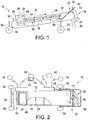
- the apparatus 10 comprises a conveyor 16 within a housing 12, the conveyor 16 positioned generally horizontally to provide a low profile to enable positioning of the apparatus 10 underneath a hopper-bottom bin or similar seed storage unit, the conveyor configured to move seed 36 on the top of the conveyor 16 in the direction of the arrow in Figure 1 .
- the housing 12 comprises a seed intake 24 at a first end 18 of the conveyor 16 and a seed outlet 26 at a second end 20 of the conveyor 16.
- a conventional motor 22 is shown in the illustrated embodiment as being mounted on a side of the housing 12 for providing power to the conveyor 16, the motor being connected to a power source 74 and a controller 50 in a manner determinable by those skilled in the art.
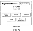
- the conveyor 16 which is a continuous belt in the embodiment shown in Figures 1 through 5 , is provided with a series of spaced apart cleats 28, the cleats mounted on the conveyor 16 at a first edge 30, the second edge 32 of each cleat 28 directed toward an inner surface 14 of the housing 12.
- the cleats 28 are equally spaced along the conveyor 16 and rigidly mounted perpendicular to the conveyor surface to avoid forward or rearward bending when retaining and transporting seed 36; it will be obvious to those skilled in the art, however, that the cleats 28 could be mounted in such a way that they are disposed off of the vertical and still achieve the desired functionality.
- the conveyor 16 two adjacent cleats 28 and surrounding housing 12 walls define a generally cuboid receiving void for receipt and transport of seed 36 to be treated, and the series of equally spaced cleats 28 therefore provide a continuous series of such voids of equal volume.
- the consistency of volumes in series allows calculation of an appropriate amount of treatment 38 application.
- the cleats 28 are also preferably composed of a flexible material to avoid crushing of seed 36 that might get caught against the housing 12 inner walls during movement of the conveyor 16.
- Figures 12a and 12b illustrate an alternative conveyor 16a, which is in the form of a horizontally disposed wheel that rotates about a vertical axis.
- this alternative embodiment illustrates a further configuration that embodies the present invention where the voids are generally triangular.
- the conveyor 16a is housed within a circular housing 12a and rotates about its vertical axis in the direction shown by the arrow in Figure 12b , the voids defined in part by cleats 28a.
- the intake 24a is located at a first end 18a of the conveyor 16a and comprises an aperture in the upper surface of the housing 12a, which aperture opens into a triangular void.
- Seed can be deposited into the triangular void through the intake 24a.
- the intake 24a may be larger than the width of an individual void, which has been found to be helpful in ensuring a complete filling of the void at certain higher operating speeds.
- a drive mechanism which could for example be situated beside or under the housing 12a
- the outlet 26a which comprises an aperture located at a second end 20a of the conveyor 16a in the lower surface of the housing 12a; once the void is positioned over the outlet 26a the seed is allowed to fall downwardly out of the void through the outlet 26a.
- the alternative conveyor 16a functions in a similar manner to the conveyor 16 of Figures 1 through 5 , although empty voids return to the intake 24a on the same horizontal plane as the filled voids rather than passing rearwardly on the underside of the belt-like conveyor 16.
- the conveyor 16a and housing 12a could also be provided with a channeling collar as is illustrated in Figure 1 , to channel seed toward the intake 24a, or the housing 12a could be raised into position against a bin outlet by means known in the art.
- Other alternative conveyor configurations will be obvious to one skilled in the art.
- the housing 12 comprises a channeling collar 54 mounted on the intake 24.
- the collar 54 is composed of a flexible material that folds in an accordion-like fashion.
- the collar 54 may be positionable in any degree of upward extension, or it may be biased upwardly into an extended position by means known to those skilled in the art such as external or internally integrated springs.
- the purpose of the collar 54 is to channel seed 36 from an overlying storage unit toward the intake 24, which collar 54 may be spaced from the storage unit outlet or sealingly engaged with it. This feature allows the user to avoid seed loss due to misalignment of the storage unit outlet and the intake 24 and also due to wind.
- the collar 54 also functions to allow flooding of the conveyor 16 with seed 36 to ensure accuracy of volume flow determination.
- the apparatus 10 is also provided with a handle 68 and wheels 58 to enable a user to move the apparatus 10 into position beneath a seed storage unit.
- the wheels 58 can be caster wheels, and they are mounted on extensible legs 56 in the illustrated embodiment, as can best be seen in Figures 1 , 3 and 4 .
- the extensible legs 56 allow the user to vertically adjust the rear of the apparatus 10 to better position the intake 24 for receipt of seed 36, but also to raise the front of the apparatus 10 slightly to enhance the area for spraying treatment 38 on the metered seed 36.
- Figures 1 and 2 show the position of a scraper or brush 44 which is mounted on the inner surface 14 of the housing 12 adjacent the intake 24.
- the brush 44 is an elongate member that extends across the width of the housing 12 and is generally equivalent in length to a cleat 28.
- the brush 44 functions to help level off the seed 36 that has been received in each cuboid void, helping to ensure consistent seed 36 volumes in each void.
- Figure 5 provides a detailed illustration of the interface between the brush 44 and a cleat 28. While the void could be initially filled above the second edge 32 of the cleat 28, the conveyor 16 moves the cleats 28 and received seed 36 past the brush 44, thereby scraping off the excess seed 36 such that it remains in the intake 24 area.
- the above description is addressed to the metering functionality of the apparatus 10, whereby determinable volumes of seed 36 in each cuboid void result in a determinable volume flow through the apparatus 10.
- the apparatus 10 is also provided with seed treating functionality, where the metered seed 36 is provided with treatment 38.
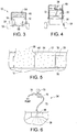
- the seed treatment applicator 34 is positioned at the front end of the apparatus 10 over the conveyor outlet 26 and comprises a housing for directing metered seed 36 downwardly past a spray nozzle 48.
- a pump 46 (such as a peristaltic pump) is mounted on a side of the housing 12 for drawing treatment 38 from a treatment source 40 such as a barrel, and the pump is connected to both a power source 74 and the controller 50.
- the pump 46 is configured to draw treatment 38 from the treatment source 40 and direct the treatment 38 through treatment lines 72 toward the nozzle 48.
- the treatment line 72 can be connected to valves 76 and a pressure gauge 70 in a conventional manner to control and monitor the passage of treatment 38.
- the treatment 38 is sprayed rearwardly within the seed treatment applicator 34 housing, as the seed 36 passes downwardly from the conveyor outlet 26 and past the nozzle 48 to the treated seed outlet 42.
- a second nozzle on a rearward side of the seed treatment applicator 34 housing opposite to the nozzle 48, with spray toward the front of the apparatus 10, such that seed 36 is sprayed from front and back as it falls toward the treated seed outlet 42.
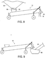
- Figures 8 and 9 illustrate the interface of the apparatus 10 with adjacent equipment.
- Figure 8 illustrates the apparatus 10 receiving seed 36 from a bopper-bottom bin 64, where the collar 54 is upwardly extended to sealingly engage the bin outlet 66.
- this form of engagement has the advantage of keeping the intake 24 consistently full during operation of the apparatus 10 while reducing the chance of spillage or wind loss.
- Figure 9 illustrates the positioning of an auger hopper 60 and mixing auger 62 at the discharge end of the apparatus 10. After the seed 36 has been sprayed with treatment 38, it falls through the treated seed outlet 42 into the hopper 60, where the seed 36 is then drawn up into the auger for mixing and more uniform coating of the seed 36 before being ultimately discharged into a truck or another storage unit.
- the auger hopper 60 could also be integrated with the front end of the apparatus 10 rather than be a separate piece of equipment, thereby further reducing exposure points.
- the controller 50 is connected to both the conveyor motor 22 and the pump 46, and is used to control both the speed of the conveyor 16 and the rate of treatment 38 application, as will be discussed below.
- the controller 50 comprises a programmable logic controller, a data storage, a user interface and a display.
- the user interface and display are collectively a touchscreen 52, as seen in Figure 2 .
- Standard application rates are normally provided in mL/100kg, or volume/mass.
- Density is mass per unit volume, so if one knows the density for a particular seed to be treated, the mass can be determined based on that density and a measured seed volume, allowing the user to calculate an optimal application rate.
- the following two examples are illustrative of a method according to the present invention.
- test apparatus had a single-revolution volume of 1.44 bushels, which figure was programmed into the controller to enable motor speed calculations.
- the actual density of the seed was measured, rather than use a standard density which can be inaccurate.
- the actual measured seed density was 67.8 lbs/bushel rather than the standard of 60 lbs/bushel.
- the application rate of Raxil MD is 300 mL/100kg of seed.
- a second test run was conducted using an apparatus in accordance with the present invention. Using a scale and a half-litre cup, the actual density of the seed was measured, rather than use a standard density which can be inaccurate. For example, in the instant example, the actual measured seed density was 55.4 lbs/bushel rather than the standard of 48 lbs/bushel.
- the application rate of Raxil WW is 363 mL/100kg of seed.
- seed is provided at step 82, followed by a determination of seed density at step 84.
- the seed is then metered at step 86 to determine the seed volume, and the seed density is used at step 88 to convert that seed volume value to a seed mass value.
- the seed mass value is then used at step 90 to calculate an optimal seed treatment application rate, followed by actual application of treatment at step 92.
- seed is provided at step 102 and a metering apparatus such as apparatus 10 described above is provided at step 104.
- the seed density is determined at step 106.
- seed density can be determined using a simple scale-and-cup method; alternatively, where a conveyor-based metering apparatus is employed as in the present invention, the conveyor itself could be provided with a weighing mechanism such as a load cell to weigh the loaded conveyor and thereby determine seed density without recourse to a separate measurement step using a scale and cup.
- the seed is metered using the apparatus at step 108 (either concurrently with or subsequent to step 106) to determine a seed volume flow through the apparatus.
- This seed volume flow through the apparatus is then converted at step 110 to a seed mass flow through the apparatus using the seed density that was determined at step 106.
- the optimal seed treatment application rate is then calculated at step 112 based on the seed mass flow through the apparatus, followed by actual application of treatment at step 114.
- the apparatus 10 is provided with a controller 50 to enable operation of the apparatus 10 and implementation of the methods according to the present invention.
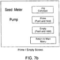
- Figures 7a to 7g screen shots are provided which illustrate the use of the controller 50 with touchscreen 52.
- Figure 7a is the first screen that is presented to the user. This main screen is facilitates operation of the controller 50.
- the Prime/Empty Screen is presented to the user, as shown in Figure 7b .
- This screen is used to prepare the apparatus 10 for operation.
- the "Jog Conveyor” button is used once the bin seed supply has been initiated and the intake 24 has been flooded with seed 36; by pressing the button, the conveyor motor 22 is powered up so as to advance the conveyor 16 one cleat 28 at a time.
- the "Prime” button is used to pump treatment 38 from the treatment source 40 to the pump 46 and into the nozzle 48.
- the “Empty” button runs the pump 46 in reverse to return unused treatment 38 to the treatment source 40 at the completion of treatment.
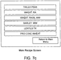
- the main screen presents the user with a list of pre-programmed "recipes" or settings that are required for treatment application for different seed types. Preprogramming such settings allows the user to quickly return to needed settings.
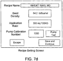
- This Recipe Setting Screen contains the information necessary for the proper control of the conveyor motor 22 and pump 46.
- the user can enter a recipe name (a keypad pops up upon selecting this item) and must enter a seed density, which seed density can be determined using a half-litre cup and scale as indicated above. As stated above, this seed density is used by the controller to convert the volume flow of the conveyor 16 to a mass flow.
- the application rate must also be entered by the user and is normally found on the treatment product label, expressed in mL/100kg.
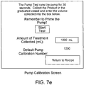
- the pump calibration number defaults to 1000 which is 100%, but this can be changed manually or through a pump test.
- the controller calculates how fast to turn the conveyor 16 based on the bushels required per minute, and uses the seed density to convert this volume to a mass flow through the apparatus 10.
- the mass flow is required as the application rate of treatment entered in the recipe is based on mL/100kg. From this information, the controller then calculates how fast to turn the pump 46 to get the calculated optimal application rate of treatment.
- the controller uses proportional control to operate the pump 46 at the correct speed relative to the conveyor 16 speed; in this way the application rate is as desired regardless of the seed flow selected, and this control reduces the amount of calibration necessary when changing products and flow rates.
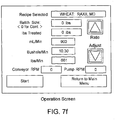
- the controller allows the user to select a certain batch size of seed 36 to be treated.
- a further screen appears allowing the user to enter a seed amount in lbs. If a batch amount is entered, then the "lbs Treated” line is activated and tracks the amount of seed left to be treated in the batch. In this batch mode of operation, the unit will run until the set-point is reached and then the pump 46 and conveyor 16 will be shut off. If “0" is chosen as the batch size, the unit will run continuously until the "Stop” button is pressed on the touchscreen 52, and the "lbs Treated” line will display the seed that has been treated as the unit is running. The conveyor rpm and pump rpm are also displayed, and will display "0" until the unit is running.
- the user can also select the "Totals” button, which will display a Totals Screen as shown in Figure 7g .
- This screen tracks the treatment in progress, with options to track and save data for two batches and the treatment used. The screen also displays the lifetime treatment total of seed for the unit.
- the "Setup/Maintenance” button can display a screen (not shown) for changing units from Imperial to Metric or any number of other settings.
- the apparatus of the present invention present significant advantages over the prior art.
- the apparatus provides for metering based on positive displacement instead of an inaccurate screw-type auger, with a low profile due to a horizontally disposed conveyor (both the belt-type conveyor and circular conveyor) so it can fit under common hopper-bottom bins.
- the apparatus and methods according to the present invention incorporate a seed density determination to provide more accurate treatment application.
Landscapes
- Life Sciences & Earth Sciences (AREA)
- Soil Sciences (AREA)
- Environmental Sciences (AREA)
- Engineering & Computer Science (AREA)
- Mechanical Engineering (AREA)
- Pretreatment Of Seeds And Plants (AREA)
- Apparatuses For Bulk Treatment Of Fruits And Vegetables And Apparatuses For Preparing Feeds (AREA)
- Sowing (AREA)
Claims (14)
- Saatgutbehandlungsvorrichtung (10) umfassend: ein Gehäuse (12, 12a) mit einer Innenfläche (14); einen Förderer (16, 16a), der im Allgemeinen horizontal innerhalb des Gehäuses (12, 12a) angeordnet ist, wobei der Förderer (16, 16a) ein erstes (18, 18a) und ein zweites (20, 20a) Ende, die voneinander beabstandet sind, sowie einen Fördererantriebsmechanismus (22) aufweist; einen an das erste Ende (18, 18a) angrenzenden Förderereinlass (24, 24a) zum Aufnehmen von Saatgut (36); einen an das zweite Ende (20) angrenzenden Fördererauslass (26, 26a) zum Ausstoßen des Saatguts (36); einen an den Fördererauslass (26, 26a) angrenzenden Saatgutbehandlungsapplikator (34) zum Aufnehmen des ausgestoßenen Saatguts (36) und Anwenden einer Saatgutbehandlung (38) auf das Saatgut (36); und eine mit dem Saatgutbehandlungsapplikator (34) in Fluidverbindung stehende Saatgutbehandlungsquelle (40) zum Bereitstellen der Saatgutbehandlung (38); dadurch gekennzeichnet, dass die Vorrichtung (10) ferner mehrere Leisten (28, 28a) umfasst, die jede eine erste und eine zweite Kante (30 und 32) aufweisen, die einander gegenüberliegen, wobei die Leisten (28, 28a) an ihrer ersten Kante (30) an einer Außenfläche des Förderers (16, 16a) in gleichmäßig beabstandeten Intervallen montiert sind, wobei sich die zweiten Kanten (32) der Leisten (28, 28a) zur Innenfläche (14) des Gehäuses (12, 12a) erstrecken, und dass die Vorrichtung (10) ferner einen Abstreifer (44) umfasst, der sich von der Innenfläche (14) des Gehäuses (12, 12a) an den Einlass (24) angrenzend abwärts erstreckt, wobei der Abstreifer (44) eine Länge, die im Wesentlichen gleich einem Abstand zwischen der Innenfläche (14) des Gehäuses (12, 12a) und den zweiten Kanten (32) der Leisten (28, 28a) ist, und eine Breite, die im Wesentlichen gleich den Leisten (28, 28a) ist, aufweist, sodass die Außenfläche und der Abstreifer (44) und die Leisten (28, 28a) gemeinsam eine Reihe quaderförmiger Hohlräume zum Aufnehmen und Transportieren bestimmbarer Mengen des Saatguts (36) definieren, sodass, wenn der Leisten (28, 28a) den Abstreifer (44) passiert, der Abstreifer (44) das empfangene Saatgut (36) abzieht, sodass das empfangene Saatgut (36) im Allgemeinen bündig mit den zweiten Kanten (32) der Leisten (28, 28a) abschließt, wodurch einheitliche Saatgutmengen in jedem quaderförmigen Hohlraum gewährleistet werden.
- Vorrichtung (10) nach Anspruch 1, wobei das Gehäuse (12, 12a) den Förderereinlass (24, 24a) und den Fördererauslass (26, 26a) umfasst.
- Vorrichtung (10) nach Anspruch 1, wobei das Gehäuse (12, 12a) den Saatgutbehandlungsapplikator (34) enthält und einen Samenbehandlungsauslass (42) umfasst.
- Vorrichtung (10) nach Anspruch 1, wobei der Abstreifer (44) eine Bürste ist.
- Vorrichtung (10) nach Anspruch 1 wobei der Förderer (16, 16a) ein Endlosbandförderer (16) ist.
- Vorrichtung (10) nach Anspruch 1, wobei der Förderer (16, 16a) ein Kreisförderer (16a) ist.
- Vorrichtung (10) nach Anspruch 1, wobei der Samenbehandlungsapplikator (34) eine peristaltische Pumpe (46) und Sprühdüsen (48) umfasst.
- Vorrichtung (10) nach Anspruch 1, ferner umfassend eine Steuerung (50) zum Steuern des Fördererantriebsmechanismus (22) und des Samenbehandlungsapplikators (34).
- Vorrichtung (10) nach Anspruch 8, wobei die Steuerung (50) eine speicherprogrammierbare Steuerung, einen Datenspeicher, eine Benutzerschnittstelle und eine Anzeige umfasst.
- Vorrichtung (10) nach Anspruch 9, wobei die Benutzerschnittstelle und die Anzeige gemeinsam ein berührungssensitiver Bildschirm (52) sind.
- Vorrichtung (10) nach Anspruch 1, ferner umfassend einen am Förderereinlass (24, 24a) montierten Kanalisierungsansatz (54) zum Lenken des Saatguts (36) zum Förderereinlass (24, 24a).
- Vorrichtung (10) nach Anspruch 11, wobei der Kanalisierungsansatz (54) nach oben vorgespannt ist, um abdichtend mit einer Quelle des Saatguts (36) in Eingriff zu stehen.
- Vorrichtung (10) nach Anspruch 1, ferner umfassend ein ausziehbarer Träger (56) am Gehäuse (12, 12a) zum selektiven Anheben des zweiten Endes (20, 20a) des Förderers (16, 16a).
- Vorrichtung (10) nach Anspruch 1, ferner umfassend zumindest ein bodenberührendes Rad (58), um die Verlagerung der Vorrichtung (10) zu ermöglichen.
Priority Applications (1)
| Application Number | Priority Date | Filing Date | Title |
|---|---|---|---|
| PL12880924T PL2869686T3 (pl) | 2012-07-09 | 2012-07-09 | Niskoprofilowe urządzenie do zaprawiania nasion z funkcją dozowania |
Applications Claiming Priority (1)
| Application Number | Priority Date | Filing Date | Title |
|---|---|---|---|
| PCT/CA2012/000641 WO2014008571A1 (en) | 2012-07-09 | 2012-07-09 | Low profile seed treater with metering functionality |
Publications (3)
| Publication Number | Publication Date |
|---|---|
| EP2869686A1 EP2869686A1 (de) | 2015-05-13 |
| EP2869686A4 EP2869686A4 (de) | 2016-03-02 |
| EP2869686B1 true EP2869686B1 (de) | 2019-05-22 |
Family
ID=49915275
Family Applications (1)
| Application Number | Title | Priority Date | Filing Date |
|---|---|---|---|
| EP12880924.1A Active EP2869686B1 (de) | 2012-07-09 | 2012-07-09 | Niedrigprofil-saatgutspender mit dosierungsfunktionalität |
Country Status (12)
| Country | Link |
|---|---|
| US (1) | US10631453B2 (de) |
| EP (1) | EP2869686B1 (de) |
| AP (1) | AP2014008167A0 (de) |
| AU (2) | AU2012385439B2 (de) |
| BR (1) | BR112015000343B1 (de) |
| CA (1) | CA2877860C (de) |
| EA (1) | EA030350B8 (de) |
| MX (1) | MX365400B (de) |
| PL (1) | PL2869686T3 (de) |
| UA (1) | UA116353C2 (de) |
| WO (1) | WO2014008571A1 (de) |
| ZA (1) | ZA201409326B (de) |
Cited By (1)
| Publication number | Priority date | Publication date | Assignee | Title |
|---|---|---|---|---|
| CN111003415A (zh) * | 2019-11-22 | 2020-04-14 | 丁洁纯 | 一种狭窄环境下适用的蛇形输送机 |
Families Citing this family (14)
| Publication number | Priority date | Publication date | Assignee | Title |
|---|---|---|---|---|
| AP2015008655A0 (en) | 2013-02-15 | 2015-08-31 | Growth Internat Ag | Rotatable apparatus for metering and treating agriculture granules |
| WO2015115640A1 (ja) * | 2014-02-03 | 2015-08-06 | 宇部興産株式会社 | 酸窒化物蛍光体粉末およびその製造方法 |
| US9730377B2 (en) * | 2015-06-26 | 2017-08-15 | Cnh Industrial Canada, Ltd. | Planter with on-board seed treatment |
| CN105083934A (zh) * | 2015-07-03 | 2015-11-25 | 广东工业大学 | 钱币进料装置 |
| DE102016214553A1 (de) | 2016-08-05 | 2018-02-08 | Deere & Company | Anordnung zur Erfassung der Menge an Material in einem Vorratsbehälter einer Maschine zum Ausbringen von Material auf ein Feld |
| WO2018213700A1 (en) * | 2017-05-19 | 2018-11-22 | Monsanto Technology Llc | Device, system, and method for treating seeds |
| US10582655B2 (en) | 2017-08-23 | 2020-03-10 | Cnh Industrial Canada, Ltd. | System and method for spraying fluid onto seeds dispensed from a planter |
| CA3025414C (en) * | 2017-11-27 | 2021-01-05 | Ag Growth International Inc. | Automatic calibration of seed treater metering system |
| WO2019152704A1 (en) * | 2018-02-05 | 2019-08-08 | Forsyth Daniel L | Coating flowable contact-tolerant granules, including seeds |
| RU191544U1 (ru) * | 2019-04-24 | 2019-08-12 | Федеральное государственное бюджетное образовательное учреждение высшего образования "Ульяновский государственный аграрный университет имени П.А. Столыпина" | Устройство для протравливания и погрузки зерна |
| RU193591U1 (ru) * | 2019-04-24 | 2019-11-06 | Федеральное государственное бюджетное образовательное учреждение высшего образования "Ульяновский государственный аграрный университет имени П.А. Столыпина" | Устройство для протравливания и погрузки зерна |
| US11758834B2 (en) | 2019-07-29 | 2023-09-19 | KSi Conveyor, Inc. | Method for mixing a stream of particulate material by inducing backflow within an inclined belt conveyor |
| US11994423B2 (en) | 2020-08-28 | 2024-05-28 | Renovators, Llc | Weigh belt assembly with a weigh axis that intersects a rotational axis of an idler roller |
| CN112428473A (zh) * | 2020-11-24 | 2021-03-02 | 颍上县龙裕扬工贸有限公司 | 一种自动分批次进出料的塑料制品加工用原料烘干装置 |
Family Cites Families (14)
| Publication number | Priority date | Publication date | Assignee | Title |
|---|---|---|---|---|
| GB649436A (en) * | 1947-11-24 | 1951-01-24 | Johannes Jacobus De Villiers S | Improvements in or relating to seed planting implements |
| US3765125A (en) * | 1972-07-03 | 1973-10-16 | R Amburn | Apparatus for treating seeds |
| US4023525A (en) * | 1976-08-04 | 1977-05-17 | Gustafson, Inc. | Seed treater |
| GB1568514A (en) * | 1976-10-19 | 1980-05-29 | Debreceni Mezogazasagi Gepgyar | Process and an apparatus for the dressing and/or chemical treatment of tuberous seed crops particularly seedpotatoes |
| US4208135A (en) * | 1978-11-01 | 1980-06-17 | Bastiao Manuel J | Mixing device |
| FR2593663B1 (fr) * | 1986-01-31 | 1989-04-14 | Sip Condi Film Sa | Procede de regulation de traitement de graines et de produits similaires, moyens pour la mise en oeuvre de ce procede et installations de traitement pourvues de ces moyens |
| US4993316A (en) * | 1988-05-09 | 1991-02-19 | Agrichem, Inc. | Seed grain conditioning apparatus |
| CA2196001C (en) | 1997-01-27 | 2002-12-17 | Robert J. Graham | G3 seed treater |
| GB9914795D0 (en) * | 1999-06-25 | 1999-08-25 | Perry Of Oakley Limited | Application systems |
| CA2333834A1 (en) | 2001-02-05 | 2002-08-05 | Blaine Muhr | Seed inoculation system |
| EP1285562A1 (de) * | 2001-08-21 | 2003-02-26 | Ion Beam Applications S.A. | Verfahren und Vorrichtung zum Bestrahlen von Schüttgütern |
| US7869902B2 (en) * | 2007-11-13 | 2011-01-11 | Pioneer Hi-Bred International, Inc. | Intelligent seed treatment system and method |
| US8258951B2 (en) * | 2008-03-14 | 2012-09-04 | The Invention Science Fund I, Llc | Method and system for correlating external data to a plant with an electronic tag |
| WO2011017252A1 (en) * | 2009-08-03 | 2011-02-10 | Bayer Cropscience Lp | Seed treatment apparatus |
-
2012
- 2012-07-09 WO PCT/CA2012/000641 patent/WO2014008571A1/en not_active Ceased
- 2012-07-09 EP EP12880924.1A patent/EP2869686B1/de active Active
- 2012-07-09 PL PL12880924T patent/PL2869686T3/pl unknown
- 2012-07-09 AP AP2014008167A patent/AP2014008167A0/xx unknown
- 2012-07-09 US US14/413,331 patent/US10631453B2/en active Active
- 2012-07-09 CA CA2877860A patent/CA2877860C/en active Active
- 2012-07-09 UA UAA201500956A patent/UA116353C2/uk unknown
- 2012-07-09 EA EA201590104A patent/EA030350B8/ru not_active IP Right Cessation
- 2012-07-09 AU AU2012385439A patent/AU2012385439B2/en not_active Ceased
- 2012-07-09 BR BR112015000343-5A patent/BR112015000343B1/pt not_active IP Right Cessation
- 2012-07-09 MX MX2015000299A patent/MX365400B/es active IP Right Grant
-
2014
- 2014-12-18 ZA ZA2014/09326A patent/ZA201409326B/en unknown
-
2018
- 2018-06-22 AU AU2018204535A patent/AU2018204535A1/en not_active Abandoned
Non-Patent Citations (1)
| Title |
|---|
| None * |
Cited By (2)
| Publication number | Priority date | Publication date | Assignee | Title |
|---|---|---|---|---|
| CN111003415A (zh) * | 2019-11-22 | 2020-04-14 | 丁洁纯 | 一种狭窄环境下适用的蛇形输送机 |
| CN111003415B (zh) * | 2019-11-22 | 2021-04-27 | 双鸭山市金诺恒业机械制造有限公司 | 一种狭窄环境下适用的蛇形输送机 |
Also Published As
| Publication number | Publication date |
|---|---|
| AU2018204535A1 (en) | 2018-07-12 |
| BR112015000343A2 (pt) | 2017-06-27 |
| US20150359164A1 (en) | 2015-12-17 |
| CA2877860C (en) | 2018-05-01 |
| BR112015000343B1 (pt) | 2019-10-29 |
| AU2012385439B2 (en) | 2018-04-05 |
| MX2015000299A (es) | 2015-07-23 |
| UA116353C2 (uk) | 2018-03-12 |
| PL2869686T3 (pl) | 2019-11-29 |
| EP2869686A1 (de) | 2015-05-13 |
| WO2014008571A1 (en) | 2014-01-16 |
| EP2869686A4 (de) | 2016-03-02 |
| US10631453B2 (en) | 2020-04-28 |
| EA030350B1 (ru) | 2018-07-31 |
| EA030350B8 (ru) | 2018-10-31 |
| CA2877860A1 (en) | 2014-01-16 |
| ZA201409326B (en) | 2016-09-28 |
| AU2012385439A1 (en) | 2015-01-29 |
| AP2014008167A0 (en) | 2014-12-31 |
| MX365400B (es) | 2019-05-31 |
| EA201590104A1 (ru) | 2015-10-30 |
Similar Documents
| Publication | Publication Date | Title |
|---|---|---|
| EP2869686B1 (de) | Niedrigprofil-saatgutspender mit dosierungsfunktionalität | |
| US11291154B2 (en) | Seed treatment apparatus | |
| US10813275B2 (en) | System and method for independent calibration of meter rollers | |
| US8408478B2 (en) | Product distribution apparatus with system and method of automatic meter calibration | |
| US8683930B2 (en) | Side mounted air seeder product container | |
| US20160302352A1 (en) | High redundancy seed coating apparatus and method | |
| EP2698064B1 (de) | Vorrichtung zur Bereitstellung eines Teigprodukts mit Garnierungsmaterial | |
| EP1625787B1 (de) | Anlage zum Trennen und Mischen von Viehfutter | |
| KR20210050815A (ko) | 분말 농약 정량 투입기 | |
| KR20190075781A (ko) | 포장 작업기 | |
| WO2014124518A1 (en) | Rotatable apparatus for metering and treating agricultural granules | |
| US20050283273A1 (en) | Apparatus and method for substantially continuous delivery of a substantially constant weight of material per unit of time from a bulk storage location and for weighing, blending, and mixing conveyable materials | |
| US20250127074A1 (en) | Portable Seed Treatment System mounted with a Calibration Hopper and Inline Conveyors | |
| US20260020518A1 (en) | Seed conveyor | |
| WO2019088823A1 (en) | A dispensing apparatus | |
| US20250120332A1 (en) | Automated Systems And Methods For Treating Seeds | |
| JPS6245488B2 (de) | ||
| CN108077976A (zh) | 一种千分级后喷涂系统 | |
| PL219468B1 (pl) | Sposób i urządzenie do dozowania nasion i zaprawy, zwłaszcza w zaprawiarkach do nasion | |
| TWM552742U (zh) | 食品材料定量供給裝置 | |
| PL202853B1 (pl) | Sposób i urządzenie do dozowania cieczy i nasion, zwłaszcza w zaprawiarkach do nasion |
Legal Events
| Date | Code | Title | Description |
|---|---|---|---|
| PUAI | Public reference made under article 153(3) epc to a published international application that has entered the european phase |
Free format text: ORIGINAL CODE: 0009012 |
|
| 17P | Request for examination filed |
Effective date: 20150209 |
|
| AK | Designated contracting states |
Kind code of ref document: A1 Designated state(s): AL AT BE BG CH CY CZ DE DK EE ES FI FR GB GR HR HU IE IS IT LI LT LU LV MC MK MT NL NO PL PT RO RS SE SI SK SM TR |
|
| AX | Request for extension of the european patent |
Extension state: BA ME |
|
| DAX | Request for extension of the european patent (deleted) | ||
| RA4 | Supplementary search report drawn up and despatched (corrected) |
Effective date: 20160203 |
|
| RIC1 | Information provided on ipc code assigned before grant |
Ipc: A01C 1/06 20060101AFI20160128BHEP Ipc: B65G 15/00 20060101ALI20160128BHEP Ipc: B65G 15/44 20060101ALI20160128BHEP Ipc: A01C 1/00 20060101ALI20160128BHEP Ipc: B65G 15/42 20060101ALI20160128BHEP |
|
| STAA | Information on the status of an ep patent application or granted ep patent |
Free format text: STATUS: EXAMINATION IS IN PROGRESS |
|
| 17Q | First examination report despatched |
Effective date: 20180117 |
|
| GRAP | Despatch of communication of intention to grant a patent |
Free format text: ORIGINAL CODE: EPIDOSNIGR1 |
|
| STAA | Information on the status of an ep patent application or granted ep patent |
Free format text: STATUS: GRANT OF PATENT IS INTENDED |
|
| INTG | Intention to grant announced |
Effective date: 20180822 |
|
| GRAS | Grant fee paid |
Free format text: ORIGINAL CODE: EPIDOSNIGR3 |
|
| GRAA | (expected) grant |
Free format text: ORIGINAL CODE: 0009210 |
|
| STAA | Information on the status of an ep patent application or granted ep patent |
Free format text: STATUS: THE PATENT HAS BEEN GRANTED |
|
| AK | Designated contracting states |
Kind code of ref document: B1 Designated state(s): AL AT BE BG CH CY CZ DE DK EE ES FI FR GB GR HR HU IE IS IT LI LT LU LV MC MK MT NL NO PL PT RO RS SE SI SK SM TR |
|
| REG | Reference to a national code |
Ref country code: GB Ref legal event code: FG4D |
|
| REG | Reference to a national code |
Ref country code: CH Ref legal event code: EP |
|
| REG | Reference to a national code |
Ref country code: IE Ref legal event code: FG4D |
|
| REG | Reference to a national code |
Ref country code: DE Ref legal event code: R096 Ref document number: 602012060503 Country of ref document: DE |
|
| REG | Reference to a national code |
Ref country code: AT Ref legal event code: REF Ref document number: 1134933 Country of ref document: AT Kind code of ref document: T Effective date: 20190615 |
|
| REG | Reference to a national code |
Ref country code: NL Ref legal event code: MP Effective date: 20190522 |
|
| REG | Reference to a national code |
Ref country code: LT Ref legal event code: MG4D |
|
| PG25 | Lapsed in a contracting state [announced via postgrant information from national office to epo] |
Ref country code: ES Free format text: LAPSE BECAUSE OF FAILURE TO SUBMIT A TRANSLATION OF THE DESCRIPTION OR TO PAY THE FEE WITHIN THE PRESCRIBED TIME-LIMIT Effective date: 20190522 Ref country code: NL Free format text: LAPSE BECAUSE OF FAILURE TO SUBMIT A TRANSLATION OF THE DESCRIPTION OR TO PAY THE FEE WITHIN THE PRESCRIBED TIME-LIMIT Effective date: 20190522 Ref country code: LT Free format text: LAPSE BECAUSE OF FAILURE TO SUBMIT A TRANSLATION OF THE DESCRIPTION OR TO PAY THE FEE WITHIN THE PRESCRIBED TIME-LIMIT Effective date: 20190522 Ref country code: HR Free format text: LAPSE BECAUSE OF FAILURE TO SUBMIT A TRANSLATION OF THE DESCRIPTION OR TO PAY THE FEE WITHIN THE PRESCRIBED TIME-LIMIT Effective date: 20190522 Ref country code: NO Free format text: LAPSE BECAUSE OF FAILURE TO SUBMIT A TRANSLATION OF THE DESCRIPTION OR TO PAY THE FEE WITHIN THE PRESCRIBED TIME-LIMIT Effective date: 20190822 Ref country code: FI Free format text: LAPSE BECAUSE OF FAILURE TO SUBMIT A TRANSLATION OF THE DESCRIPTION OR TO PAY THE FEE WITHIN THE PRESCRIBED TIME-LIMIT Effective date: 20190522 Ref country code: PT Free format text: LAPSE BECAUSE OF FAILURE TO SUBMIT A TRANSLATION OF THE DESCRIPTION OR TO PAY THE FEE WITHIN THE PRESCRIBED TIME-LIMIT Effective date: 20190922 Ref country code: SE Free format text: LAPSE BECAUSE OF FAILURE TO SUBMIT A TRANSLATION OF THE DESCRIPTION OR TO PAY THE FEE WITHIN THE PRESCRIBED TIME-LIMIT Effective date: 20190522 Ref country code: AL Free format text: LAPSE BECAUSE OF FAILURE TO SUBMIT A TRANSLATION OF THE DESCRIPTION OR TO PAY THE FEE WITHIN THE PRESCRIBED TIME-LIMIT Effective date: 20190522 |
|
| PG25 | Lapsed in a contracting state [announced via postgrant information from national office to epo] |
Ref country code: LV Free format text: LAPSE BECAUSE OF FAILURE TO SUBMIT A TRANSLATION OF THE DESCRIPTION OR TO PAY THE FEE WITHIN THE PRESCRIBED TIME-LIMIT Effective date: 20190522 Ref country code: GR Free format text: LAPSE BECAUSE OF FAILURE TO SUBMIT A TRANSLATION OF THE DESCRIPTION OR TO PAY THE FEE WITHIN THE PRESCRIBED TIME-LIMIT Effective date: 20190823 Ref country code: BG Free format text: LAPSE BECAUSE OF FAILURE TO SUBMIT A TRANSLATION OF THE DESCRIPTION OR TO PAY THE FEE WITHIN THE PRESCRIBED TIME-LIMIT Effective date: 20190822 Ref country code: RS Free format text: LAPSE BECAUSE OF FAILURE TO SUBMIT A TRANSLATION OF THE DESCRIPTION OR TO PAY THE FEE WITHIN THE PRESCRIBED TIME-LIMIT Effective date: 20190522 |
|
| PG25 | Lapsed in a contracting state [announced via postgrant information from national office to epo] |
Ref country code: CZ Free format text: LAPSE BECAUSE OF FAILURE TO SUBMIT A TRANSLATION OF THE DESCRIPTION OR TO PAY THE FEE WITHIN THE PRESCRIBED TIME-LIMIT Effective date: 20190522 Ref country code: RO Free format text: LAPSE BECAUSE OF FAILURE TO SUBMIT A TRANSLATION OF THE DESCRIPTION OR TO PAY THE FEE WITHIN THE PRESCRIBED TIME-LIMIT Effective date: 20190522 Ref country code: SK Free format text: LAPSE BECAUSE OF FAILURE TO SUBMIT A TRANSLATION OF THE DESCRIPTION OR TO PAY THE FEE WITHIN THE PRESCRIBED TIME-LIMIT Effective date: 20190522 Ref country code: EE Free format text: LAPSE BECAUSE OF FAILURE TO SUBMIT A TRANSLATION OF THE DESCRIPTION OR TO PAY THE FEE WITHIN THE PRESCRIBED TIME-LIMIT Effective date: 20190522 Ref country code: DK Free format text: LAPSE BECAUSE OF FAILURE TO SUBMIT A TRANSLATION OF THE DESCRIPTION OR TO PAY THE FEE WITHIN THE PRESCRIBED TIME-LIMIT Effective date: 20190522 |
|
| REG | Reference to a national code |
Ref country code: DE Ref legal event code: R097 Ref document number: 602012060503 Country of ref document: DE |
|
| PG25 | Lapsed in a contracting state [announced via postgrant information from national office to epo] |
Ref country code: SM Free format text: LAPSE BECAUSE OF FAILURE TO SUBMIT A TRANSLATION OF THE DESCRIPTION OR TO PAY THE FEE WITHIN THE PRESCRIBED TIME-LIMIT Effective date: 20190522 Ref country code: MC Free format text: LAPSE BECAUSE OF FAILURE TO SUBMIT A TRANSLATION OF THE DESCRIPTION OR TO PAY THE FEE WITHIN THE PRESCRIBED TIME-LIMIT Effective date: 20190522 |
|
| REG | Reference to a national code |
Ref country code: CH Ref legal event code: PL |
|
| PLBE | No opposition filed within time limit |
Free format text: ORIGINAL CODE: 0009261 |
|
| STAA | Information on the status of an ep patent application or granted ep patent |
Free format text: STATUS: NO OPPOSITION FILED WITHIN TIME LIMIT |
|
| PG25 | Lapsed in a contracting state [announced via postgrant information from national office to epo] |
Ref country code: TR Free format text: LAPSE BECAUSE OF FAILURE TO SUBMIT A TRANSLATION OF THE DESCRIPTION OR TO PAY THE FEE WITHIN THE PRESCRIBED TIME-LIMIT Effective date: 20190522 |
|
| REG | Reference to a national code |
Ref country code: BE Ref legal event code: MM Effective date: 20190731 |
|
| 26N | No opposition filed |
Effective date: 20200225 |
|
| PG25 | Lapsed in a contracting state [announced via postgrant information from national office to epo] |
Ref country code: LU Free format text: LAPSE BECAUSE OF NON-PAYMENT OF DUE FEES Effective date: 20190709 Ref country code: SI Free format text: LAPSE BECAUSE OF FAILURE TO SUBMIT A TRANSLATION OF THE DESCRIPTION OR TO PAY THE FEE WITHIN THE PRESCRIBED TIME-LIMIT Effective date: 20190522 Ref country code: LI Free format text: LAPSE BECAUSE OF NON-PAYMENT OF DUE FEES Effective date: 20190731 Ref country code: CH Free format text: LAPSE BECAUSE OF NON-PAYMENT OF DUE FEES Effective date: 20190731 Ref country code: BE Free format text: LAPSE BECAUSE OF NON-PAYMENT OF DUE FEES Effective date: 20190731 |
|
| REG | Reference to a national code |
Ref country code: AT Ref legal event code: UEP Ref document number: 1134933 Country of ref document: AT Kind code of ref document: T Effective date: 20190522 |
|
| PG25 | Lapsed in a contracting state [announced via postgrant information from national office to epo] |
Ref country code: IE Free format text: LAPSE BECAUSE OF NON-PAYMENT OF DUE FEES Effective date: 20190709 |
|
| PG25 | Lapsed in a contracting state [announced via postgrant information from national office to epo] |
Ref country code: CY Free format text: LAPSE BECAUSE OF FAILURE TO SUBMIT A TRANSLATION OF THE DESCRIPTION OR TO PAY THE FEE WITHIN THE PRESCRIBED TIME-LIMIT Effective date: 20190522 |
|
| PG25 | Lapsed in a contracting state [announced via postgrant information from national office to epo] |
Ref country code: IS Free format text: LAPSE BECAUSE OF FAILURE TO SUBMIT A TRANSLATION OF THE DESCRIPTION OR TO PAY THE FEE WITHIN THE PRESCRIBED TIME-LIMIT Effective date: 20190922 |
|
| PG25 | Lapsed in a contracting state [announced via postgrant information from national office to epo] |
Ref country code: MT Free format text: LAPSE BECAUSE OF FAILURE TO SUBMIT A TRANSLATION OF THE DESCRIPTION OR TO PAY THE FEE WITHIN THE PRESCRIBED TIME-LIMIT Effective date: 20190522 Ref country code: HU Free format text: LAPSE BECAUSE OF FAILURE TO SUBMIT A TRANSLATION OF THE DESCRIPTION OR TO PAY THE FEE WITHIN THE PRESCRIBED TIME-LIMIT; INVALID AB INITIO Effective date: 20120709 |
|
| PG25 | Lapsed in a contracting state [announced via postgrant information from national office to epo] |
Ref country code: MK Free format text: LAPSE BECAUSE OF FAILURE TO SUBMIT A TRANSLATION OF THE DESCRIPTION OR TO PAY THE FEE WITHIN THE PRESCRIBED TIME-LIMIT Effective date: 20190522 |
|
| PGFP | Annual fee paid to national office [announced via postgrant information from national office to epo] |
Ref country code: FR Payment date: 20230622 Year of fee payment: 12 |
|
| PGFP | Annual fee paid to national office [announced via postgrant information from national office to epo] |
Ref country code: PL Payment date: 20230627 Year of fee payment: 12 |
|
| PGFP | Annual fee paid to national office [announced via postgrant information from national office to epo] |
Ref country code: IT Payment date: 20230627 Year of fee payment: 12 Ref country code: GB Payment date: 20230622 Year of fee payment: 12 Ref country code: AT Payment date: 20230626 Year of fee payment: 12 |
|
| PGFP | Annual fee paid to national office [announced via postgrant information from national office to epo] |
Ref country code: DE Payment date: 20230620 Year of fee payment: 12 |
|
| REG | Reference to a national code |
Ref country code: DE Ref legal event code: R119 Ref document number: 602012060503 Country of ref document: DE |
|
| REG | Reference to a national code |
Ref country code: AT Ref legal event code: MM01 Ref document number: 1134933 Country of ref document: AT Kind code of ref document: T Effective date: 20240709 |
|
| GBPC | Gb: european patent ceased through non-payment of renewal fee |
Effective date: 20240709 |
|
| PG25 | Lapsed in a contracting state [announced via postgrant information from national office to epo] |
Ref country code: DE Free format text: LAPSE BECAUSE OF NON-PAYMENT OF DUE FEES Effective date: 20250201 |
|
| PG25 | Lapsed in a contracting state [announced via postgrant information from national office to epo] |
Ref country code: AT Free format text: LAPSE BECAUSE OF NON-PAYMENT OF DUE FEES Effective date: 20240709 |
|
| PG25 | Lapsed in a contracting state [announced via postgrant information from national office to epo] |
Ref country code: FR Free format text: LAPSE BECAUSE OF NON-PAYMENT OF DUE FEES Effective date: 20240731 |
|
| PG25 | Lapsed in a contracting state [announced via postgrant information from national office to epo] |
Ref country code: GB Free format text: LAPSE BECAUSE OF NON-PAYMENT OF DUE FEES Effective date: 20240709 |
|
| PG25 | Lapsed in a contracting state [announced via postgrant information from national office to epo] |
Ref country code: IT Free format text: LAPSE BECAUSE OF NON-PAYMENT OF DUE FEES Effective date: 20240709 |