EP2869686B1 - Low profile seed treater with metering functionality - Google Patents
Low profile seed treater with metering functionality Download PDFInfo
- Publication number
- EP2869686B1 EP2869686B1 EP12880924.1A EP12880924A EP2869686B1 EP 2869686 B1 EP2869686 B1 EP 2869686B1 EP 12880924 A EP12880924 A EP 12880924A EP 2869686 B1 EP2869686 B1 EP 2869686B1
- Authority
- EP
- European Patent Office
- Prior art keywords
- seed
- conveyor
- housing
- cleats
- treatment
- Prior art date
- Legal status (The legal status is an assumption and is not a legal conclusion. Google has not performed a legal analysis and makes no representation as to the accuracy of the status listed.)
- Active
Links
- 238000011282 treatment Methods 0.000 claims description 80
- 239000011800 void material Substances 0.000 claims description 13
- 230000007246 mechanism Effects 0.000 claims description 7
- 239000007921 spray Substances 0.000 claims description 7
- 230000005465 channeling Effects 0.000 claims description 6
- 238000013500 data storage Methods 0.000 claims description 3
- 239000012530 fluid Substances 0.000 claims description 3
- 230000002572 peristaltic effect Effects 0.000 claims description 3
- 230000003028 elevating effect Effects 0.000 claims description 2
- 238000007599 discharging Methods 0.000 claims 1
- 238000000034 method Methods 0.000 description 12
- PXMNMQRDXWABCY-UHFFFAOYSA-N 1-(4-chlorophenyl)-4,4-dimethyl-3-(1H-1,2,4-triazol-1-ylmethyl)pentan-3-ol Chemical compound C1=NC=NN1CC(O)(C(C)(C)C)CCC1=CC=C(Cl)C=C1 PXMNMQRDXWABCY-UHFFFAOYSA-N 0.000 description 8
- 238000003860 storage Methods 0.000 description 6
- 238000012360 testing method Methods 0.000 description 6
- 238000011369 optimal treatment Methods 0.000 description 5
- 230000008901 benefit Effects 0.000 description 4
- 239000007788 liquid Substances 0.000 description 4
- 238000009306 commercial farming Methods 0.000 description 3
- 238000002156 mixing Methods 0.000 description 3
- 230000032258 transport Effects 0.000 description 3
- 239000002699 waste material Substances 0.000 description 3
- 108010016634 Seed Storage Proteins Proteins 0.000 description 2
- 238000004364 calculation method Methods 0.000 description 2
- 239000011248 coating agent Substances 0.000 description 2
- 238000000576 coating method Methods 0.000 description 2
- 239000000463 material Substances 0.000 description 2
- 238000003825 pressing Methods 0.000 description 2
- 240000005979 Hordeum vulgare Species 0.000 description 1
- 235000007340 Hordeum vulgare Nutrition 0.000 description 1
- 241000209140 Triticum Species 0.000 description 1
- 235000021307 Triticum Nutrition 0.000 description 1
- 230000009471 action Effects 0.000 description 1
- 238000013019 agitation Methods 0.000 description 1
- 238000013459 approach Methods 0.000 description 1
- 238000005452 bending Methods 0.000 description 1
- 238000010227 cup method (microbiological evaluation) Methods 0.000 description 1
- 238000006073 displacement reaction Methods 0.000 description 1
- 230000000694 effects Effects 0.000 description 1
- 239000003337 fertilizer Substances 0.000 description 1
- 239000000417 fungicide Substances 0.000 description 1
- 230000036541 health Effects 0.000 description 1
- 230000006872 improvement Effects 0.000 description 1
- 239000002917 insecticide Substances 0.000 description 1
- 238000012423 maintenance Methods 0.000 description 1
- 238000005259 measurement Methods 0.000 description 1
- 239000000575 pesticide Substances 0.000 description 1
- 238000012545 processing Methods 0.000 description 1
- 230000009467 reduction Effects 0.000 description 1
- 238000011160 research Methods 0.000 description 1
- 238000007790 scraping Methods 0.000 description 1
- 239000002002 slurry Substances 0.000 description 1
- 238000005507 spraying Methods 0.000 description 1
- 239000000126 substance Substances 0.000 description 1
- 230000001988 toxicity Effects 0.000 description 1
- 231100000419 toxicity Toxicity 0.000 description 1
- 230000007723 transport mechanism Effects 0.000 description 1
- 238000005303 weighing Methods 0.000 description 1
Images


Classifications
-
- A—HUMAN NECESSITIES
- A01—AGRICULTURE; FORESTRY; ANIMAL HUSBANDRY; HUNTING; TRAPPING; FISHING
- A01C—PLANTING; SOWING; FERTILISING
- A01C1/00—Apparatus, or methods of use thereof, for testing or treating seed, roots, or the like, prior to sowing or planting
- A01C1/06—Coating or dressing seed
-
- A—HUMAN NECESSITIES
- A01—AGRICULTURE; FORESTRY; ANIMAL HUSBANDRY; HUNTING; TRAPPING; FISHING
- A01C—PLANTING; SOWING; FERTILISING
- A01C1/00—Apparatus, or methods of use thereof, for testing or treating seed, roots, or the like, prior to sowing or planting
-
- B—PERFORMING OPERATIONS; TRANSPORTING
- B65—CONVEYING; PACKING; STORING; HANDLING THIN OR FILAMENTARY MATERIAL
- B65G—TRANSPORT OR STORAGE DEVICES, e.g. CONVEYORS FOR LOADING OR TIPPING, SHOP CONVEYOR SYSTEMS OR PNEUMATIC TUBE CONVEYORS
- B65G15/00—Conveyors having endless load-conveying surfaces, i.e. belts and like continuous members, to which tractive effort is transmitted by means other than endless driving elements of similar configuration
- B65G15/30—Belts or like endless load-carriers
- B65G15/32—Belts or like endless load-carriers made of rubber or plastics
- B65G15/42—Belts or like endless load-carriers made of rubber or plastics having ribs, ridges, or other surface projections
- B65G15/44—Belts or like endless load-carriers made of rubber or plastics having ribs, ridges, or other surface projections for impelling the loads
-
- A—HUMAN NECESSITIES
- A01—AGRICULTURE; FORESTRY; ANIMAL HUSBANDRY; HUNTING; TRAPPING; FISHING
- A01C—PLANTING; SOWING; FERTILISING
- A01C15/00—Fertiliser distributors
- A01C15/003—Bulk fertiliser or grain handling in the field or on the farm
-
- B—PERFORMING OPERATIONS; TRANSPORTING
- B65—CONVEYING; PACKING; STORING; HANDLING THIN OR FILAMENTARY MATERIAL
- B65G—TRANSPORT OR STORAGE DEVICES, e.g. CONVEYORS FOR LOADING OR TIPPING, SHOP CONVEYOR SYSTEMS OR PNEUMATIC TUBE CONVEYORS
- B65G15/00—Conveyors having endless load-conveying surfaces, i.e. belts and like continuous members, to which tractive effort is transmitted by means other than endless driving elements of similar configuration
- B65G15/30—Belts or like endless load-carriers
- B65G15/32—Belts or like endless load-carriers made of rubber or plastics
- B65G15/42—Belts or like endless load-carriers made of rubber or plastics having ribs, ridges, or other surface projections
Definitions
- the present invention relates to a seed treatment apparatus, and more particularly to a seed treatment apparatus incorporating seed metering.
- treatments may include the application of fertilizers, insecticides, pesticides and fungicides, and normally take the form of liquid chemical that is sprayed onto the seed.
- seed treatment apparatuses are commercially available, it is more common to see a farmer spray treatment directly onto seed just before it is drawn up an auger, the auger being employed to mix the treated seed in an effort to spread the treatment coating over as much seed surface as possible before planting.
- the Graham apparatus or "G3" is used with two augers, where one auger transports seed upwardly (from an auger hopper positioned under a hopper-bottom bin or similar) toward the upper intake of the seed treater, and the seed is then sprayed with treatment as it falls downwardly through the seed treater, with the second auger serving to mix the treated seed and transport it upwardly to a truck or storage unit.
- the seed falls in an annular pattern adjacent the inner surface of the treater, and a centrally-disposed nozzle sprays treatment in a conical spray pattern in an effort to contact as much seed as possible.
- the present invention accordingly seeks to provide a seed treatment apparatus that meters seed based on volume and uses mass flow based on seed density to calculate optimal treatment application rate for a given seed type, in an apparatus configuration capable of use with on-farm storage units.
- the conveyor may be a continuous belt conveyor or a circular conveyor
- the seed treatment applicator may comprise a peristaltic pump and spray nozzles.
- the apparatus may further comprise a controller for controlling the conveyor drive mechanism and the seed treatment applicator, and the controller comprises a programmable logic controller, a data storage, a user interface, and a display (the user interface and the display may collectively be a touchscreen monitor).
- Certain embodiments may further comprise a channeling collar mounted on the conveyor intake for directing the seed toward the conveyor intake, and the channeling collar may also be upwardly biased so as to sealingly engage with a source of the seed.
- the housing may also be provided with an extensible support for selectively elevating the second end of the conveyor, thereby providing an enhanced area for treatment application, and further comprising at least one ground-engaging wheel to enable relocation of the apparatus.
- the apparatus may also comprises a programmable logic controller that is programmed to convert the seed volume flow to the seed mass flow using the determined seed density value. and the programmable logic controller is programmed to calculate the optimal seed treatment application rate based on the seed mass flow.
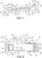
- the apparatus 10 comprises a conveyor 16 within a housing 12, the conveyor 16 positioned generally horizontally to provide a low profile to enable positioning of the apparatus 10 underneath a hopper-bottom bin or similar seed storage unit, the conveyor configured to move seed 36 on the top of the conveyor 16 in the direction of the arrow in Figure 1 .
- the housing 12 comprises a seed intake 24 at a first end 18 of the conveyor 16 and a seed outlet 26 at a second end 20 of the conveyor 16.
- a conventional motor 22 is shown in the illustrated embodiment as being mounted on a side of the housing 12 for providing power to the conveyor 16, the motor being connected to a power source 74 and a controller 50 in a manner determinable by those skilled in the art.
- the conveyor 16 which is a continuous belt in the embodiment shown in Figures 1 through 5 , is provided with a series of spaced apart cleats 28, the cleats mounted on the conveyor 16 at a first edge 30, the second edge 32 of each cleat 28 directed toward an inner surface 14 of the housing 12.
- the cleats 28 are equally spaced along the conveyor 16 and rigidly mounted perpendicular to the conveyor surface to avoid forward or rearward bending when retaining and transporting seed 36; it will be obvious to those skilled in the art, however, that the cleats 28 could be mounted in such a way that they are disposed off of the vertical and still achieve the desired functionality.
- the conveyor 16 two adjacent cleats 28 and surrounding housing 12 walls define a generally cuboid receiving void for receipt and transport of seed 36 to be treated, and the series of equally spaced cleats 28 therefore provide a continuous series of such voids of equal volume.
- the consistency of volumes in series allows calculation of an appropriate amount of treatment 38 application.
- the cleats 28 are also preferably composed of a flexible material to avoid crushing of seed 36 that might get caught against the housing 12 inner walls during movement of the conveyor 16.
- Figures 12a and 12b illustrate an alternative conveyor 16a, which is in the form of a horizontally disposed wheel that rotates about a vertical axis.
- this alternative embodiment illustrates a further configuration that embodies the present invention where the voids are generally triangular.
- the conveyor 16a is housed within a circular housing 12a and rotates about its vertical axis in the direction shown by the arrow in Figure 12b , the voids defined in part by cleats 28a.
- the intake 24a is located at a first end 18a of the conveyor 16a and comprises an aperture in the upper surface of the housing 12a, which aperture opens into a triangular void.
- Seed can be deposited into the triangular void through the intake 24a.
- the intake 24a may be larger than the width of an individual void, which has been found to be helpful in ensuring a complete filling of the void at certain higher operating speeds.
- a drive mechanism which could for example be situated beside or under the housing 12a
- the outlet 26a which comprises an aperture located at a second end 20a of the conveyor 16a in the lower surface of the housing 12a; once the void is positioned over the outlet 26a the seed is allowed to fall downwardly out of the void through the outlet 26a.
- the alternative conveyor 16a functions in a similar manner to the conveyor 16 of Figures 1 through 5 , although empty voids return to the intake 24a on the same horizontal plane as the filled voids rather than passing rearwardly on the underside of the belt-like conveyor 16.
- the conveyor 16a and housing 12a could also be provided with a channeling collar as is illustrated in Figure 1 , to channel seed toward the intake 24a, or the housing 12a could be raised into position against a bin outlet by means known in the art.
- Other alternative conveyor configurations will be obvious to one skilled in the art.
- the housing 12 comprises a channeling collar 54 mounted on the intake 24.
- the collar 54 is composed of a flexible material that folds in an accordion-like fashion.
- the collar 54 may be positionable in any degree of upward extension, or it may be biased upwardly into an extended position by means known to those skilled in the art such as external or internally integrated springs.
- the purpose of the collar 54 is to channel seed 36 from an overlying storage unit toward the intake 24, which collar 54 may be spaced from the storage unit outlet or sealingly engaged with it. This feature allows the user to avoid seed loss due to misalignment of the storage unit outlet and the intake 24 and also due to wind.
- the collar 54 also functions to allow flooding of the conveyor 16 with seed 36 to ensure accuracy of volume flow determination.
- the apparatus 10 is also provided with a handle 68 and wheels 58 to enable a user to move the apparatus 10 into position beneath a seed storage unit.
- the wheels 58 can be caster wheels, and they are mounted on extensible legs 56 in the illustrated embodiment, as can best be seen in Figures 1 , 3 and 4 .
- the extensible legs 56 allow the user to vertically adjust the rear of the apparatus 10 to better position the intake 24 for receipt of seed 36, but also to raise the front of the apparatus 10 slightly to enhance the area for spraying treatment 38 on the metered seed 36.
- Figures 1 and 2 show the position of a scraper or brush 44 which is mounted on the inner surface 14 of the housing 12 adjacent the intake 24.
- the brush 44 is an elongate member that extends across the width of the housing 12 and is generally equivalent in length to a cleat 28.
- the brush 44 functions to help level off the seed 36 that has been received in each cuboid void, helping to ensure consistent seed 36 volumes in each void.
- Figure 5 provides a detailed illustration of the interface between the brush 44 and a cleat 28. While the void could be initially filled above the second edge 32 of the cleat 28, the conveyor 16 moves the cleats 28 and received seed 36 past the brush 44, thereby scraping off the excess seed 36 such that it remains in the intake 24 area.
- the above description is addressed to the metering functionality of the apparatus 10, whereby determinable volumes of seed 36 in each cuboid void result in a determinable volume flow through the apparatus 10.
- the apparatus 10 is also provided with seed treating functionality, where the metered seed 36 is provided with treatment 38.
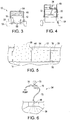
- the seed treatment applicator 34 is positioned at the front end of the apparatus 10 over the conveyor outlet 26 and comprises a housing for directing metered seed 36 downwardly past a spray nozzle 48.
- a pump 46 (such as a peristaltic pump) is mounted on a side of the housing 12 for drawing treatment 38 from a treatment source 40 such as a barrel, and the pump is connected to both a power source 74 and the controller 50.
- the pump 46 is configured to draw treatment 38 from the treatment source 40 and direct the treatment 38 through treatment lines 72 toward the nozzle 48.
- the treatment line 72 can be connected to valves 76 and a pressure gauge 70 in a conventional manner to control and monitor the passage of treatment 38.
- the treatment 38 is sprayed rearwardly within the seed treatment applicator 34 housing, as the seed 36 passes downwardly from the conveyor outlet 26 and past the nozzle 48 to the treated seed outlet 42.
- a second nozzle on a rearward side of the seed treatment applicator 34 housing opposite to the nozzle 48, with spray toward the front of the apparatus 10, such that seed 36 is sprayed from front and back as it falls toward the treated seed outlet 42.
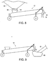
- Figures 8 and 9 illustrate the interface of the apparatus 10 with adjacent equipment.
- Figure 8 illustrates the apparatus 10 receiving seed 36 from a bopper-bottom bin 64, where the collar 54 is upwardly extended to sealingly engage the bin outlet 66.
- this form of engagement has the advantage of keeping the intake 24 consistently full during operation of the apparatus 10 while reducing the chance of spillage or wind loss.
- Figure 9 illustrates the positioning of an auger hopper 60 and mixing auger 62 at the discharge end of the apparatus 10. After the seed 36 has been sprayed with treatment 38, it falls through the treated seed outlet 42 into the hopper 60, where the seed 36 is then drawn up into the auger for mixing and more uniform coating of the seed 36 before being ultimately discharged into a truck or another storage unit.
- the auger hopper 60 could also be integrated with the front end of the apparatus 10 rather than be a separate piece of equipment, thereby further reducing exposure points.
- the controller 50 is connected to both the conveyor motor 22 and the pump 46, and is used to control both the speed of the conveyor 16 and the rate of treatment 38 application, as will be discussed below.
- the controller 50 comprises a programmable logic controller, a data storage, a user interface and a display.
- the user interface and display are collectively a touchscreen 52, as seen in Figure 2 .
- Standard application rates are normally provided in mL/100kg, or volume/mass.
- Density is mass per unit volume, so if one knows the density for a particular seed to be treated, the mass can be determined based on that density and a measured seed volume, allowing the user to calculate an optimal application rate.
- the following two examples are illustrative of a method according to the present invention.
- test apparatus had a single-revolution volume of 1.44 bushels, which figure was programmed into the controller to enable motor speed calculations.
- the actual density of the seed was measured, rather than use a standard density which can be inaccurate.
- the actual measured seed density was 67.8 lbs/bushel rather than the standard of 60 lbs/bushel.
- the application rate of Raxil MD is 300 mL/100kg of seed.
- a second test run was conducted using an apparatus in accordance with the present invention. Using a scale and a half-litre cup, the actual density of the seed was measured, rather than use a standard density which can be inaccurate. For example, in the instant example, the actual measured seed density was 55.4 lbs/bushel rather than the standard of 48 lbs/bushel.
- the application rate of Raxil WW is 363 mL/100kg of seed.
- seed is provided at step 82, followed by a determination of seed density at step 84.
- the seed is then metered at step 86 to determine the seed volume, and the seed density is used at step 88 to convert that seed volume value to a seed mass value.
- the seed mass value is then used at step 90 to calculate an optimal seed treatment application rate, followed by actual application of treatment at step 92.
- seed is provided at step 102 and a metering apparatus such as apparatus 10 described above is provided at step 104.
- the seed density is determined at step 106.
- seed density can be determined using a simple scale-and-cup method; alternatively, where a conveyor-based metering apparatus is employed as in the present invention, the conveyor itself could be provided with a weighing mechanism such as a load cell to weigh the loaded conveyor and thereby determine seed density without recourse to a separate measurement step using a scale and cup.
- the seed is metered using the apparatus at step 108 (either concurrently with or subsequent to step 106) to determine a seed volume flow through the apparatus.
- This seed volume flow through the apparatus is then converted at step 110 to a seed mass flow through the apparatus using the seed density that was determined at step 106.
- the optimal seed treatment application rate is then calculated at step 112 based on the seed mass flow through the apparatus, followed by actual application of treatment at step 114.
- the apparatus 10 is provided with a controller 50 to enable operation of the apparatus 10 and implementation of the methods according to the present invention.
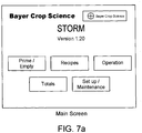
- Figures 7a to 7g screen shots are provided which illustrate the use of the controller 50 with touchscreen 52.
- Figure 7a is the first screen that is presented to the user. This main screen is facilitates operation of the controller 50.
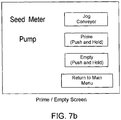
- the Prime/Empty Screen is presented to the user, as shown in Figure 7b .
- This screen is used to prepare the apparatus 10 for operation.
- the "Jog Conveyor” button is used once the bin seed supply has been initiated and the intake 24 has been flooded with seed 36; by pressing the button, the conveyor motor 22 is powered up so as to advance the conveyor 16 one cleat 28 at a time.
- the "Prime” button is used to pump treatment 38 from the treatment source 40 to the pump 46 and into the nozzle 48.
- the “Empty” button runs the pump 46 in reverse to return unused treatment 38 to the treatment source 40 at the completion of treatment.
- the main screen presents the user with a list of pre-programmed "recipes" or settings that are required for treatment application for different seed types. Preprogramming such settings allows the user to quickly return to needed settings.
- This Recipe Setting Screen contains the information necessary for the proper control of the conveyor motor 22 and pump 46.
- the user can enter a recipe name (a keypad pops up upon selecting this item) and must enter a seed density, which seed density can be determined using a half-litre cup and scale as indicated above. As stated above, this seed density is used by the controller to convert the volume flow of the conveyor 16 to a mass flow.
- the application rate must also be entered by the user and is normally found on the treatment product label, expressed in mL/100kg.
- the pump calibration number defaults to 1000 which is 100%, but this can be changed manually or through a pump test.
- the controller calculates how fast to turn the conveyor 16 based on the bushels required per minute, and uses the seed density to convert this volume to a mass flow through the apparatus 10.
- the mass flow is required as the application rate of treatment entered in the recipe is based on mL/100kg. From this information, the controller then calculates how fast to turn the pump 46 to get the calculated optimal application rate of treatment.
- the controller uses proportional control to operate the pump 46 at the correct speed relative to the conveyor 16 speed; in this way the application rate is as desired regardless of the seed flow selected, and this control reduces the amount of calibration necessary when changing products and flow rates.
- the controller allows the user to select a certain batch size of seed 36 to be treated.
- a further screen appears allowing the user to enter a seed amount in lbs. If a batch amount is entered, then the "lbs Treated” line is activated and tracks the amount of seed left to be treated in the batch. In this batch mode of operation, the unit will run until the set-point is reached and then the pump 46 and conveyor 16 will be shut off. If “0" is chosen as the batch size, the unit will run continuously until the "Stop” button is pressed on the touchscreen 52, and the "lbs Treated” line will display the seed that has been treated as the unit is running. The conveyor rpm and pump rpm are also displayed, and will display "0" until the unit is running.
- the user can also select the "Totals” button, which will display a Totals Screen as shown in Figure 7g .
- This screen tracks the treatment in progress, with options to track and save data for two batches and the treatment used. The screen also displays the lifetime treatment total of seed for the unit.
- the "Setup/Maintenance” button can display a screen (not shown) for changing units from Imperial to Metric or any number of other settings.
- the apparatus of the present invention present significant advantages over the prior art.
- the apparatus provides for metering based on positive displacement instead of an inaccurate screw-type auger, with a low profile due to a horizontally disposed conveyor (both the belt-type conveyor and circular conveyor) so it can fit under common hopper-bottom bins.
- the apparatus and methods according to the present invention incorporate a seed density determination to provide more accurate treatment application.
Description
- The present invention relates to a seed treatment apparatus, and more particularly to a seed treatment apparatus incorporating seed metering.
- It is well known in the agricultural arts to apply various treatments to seeds before planting, in an effort to reduce the amount of such treatment that would otherwise be required were it to be applied to a field after planting. For example, treatments may include the application of fertilizers, insecticides, pesticides and fungicides, and normally take the form of liquid chemical that is sprayed onto the seed. While seed treatment apparatuses are commercially available, it is more common to see a farmer spray treatment directly onto seed just before it is drawn up an auger, the auger being employed to mix the treated seed in an effort to spread the treatment coating over as much seed surface as possible before planting. Such manual application, however, normally results in overuse of expensive treatment (due to a failure to properly meter the seed and control the treatment amount) and loss of treatment (particularly due to wind) and may even have health implications depending on the nature and toxicity of the particular treatment being applied, although manual application may also result in too little treatment being applied and therefore a reduction in the desired effect.
- Various seed treatment apparatuses have been disclosed in the prior art, some of which have been made commercially available. For example, Canadian Patent No.
518,715 to Calkins provides an early example of a seed treatment device that incorporates metering of seed, where a "dump pan" is employed, but the metering approach is unfortunately inaccurate and the focus of the teaching is on slurry agitation rather than achieving optimal treatment application. Canadian Patent Application No.2,704,589 to Hunter et al. teaches a more accurate metering system, where seed weight is determined using a load cell to calculate an optimal treatment application, but the apparatus is designed for batch processing in a research setting rather than the high-throughput seed treatment required in a commercial farming operation. - One of the commercially available seed treaters for on-farm use is described in Canadian Patent No.
2.196,001 to Graham . The Graham apparatus, or "G3", is used with two augers, where one auger transports seed upwardly (from an auger hopper positioned under a hopper-bottom bin or similar) toward the upper intake of the seed treater, and the seed is then sprayed with treatment as it falls downwardly through the seed treater, with the second auger serving to mix the treated seed and transport it upwardly to a truck or storage unit. The seed falls in an annular pattern adjacent the inner surface of the treater, and a centrally-disposed nozzle sprays treatment in a conical spray pattern in an effort to contact as much seed as possible. While this apparatus may provide an improvement over manual application methods, it has been found that treatment builds up around the inner surface of the treater and is therefore wasted. However, a more significant issue has been noted with this and other auger-based treaters, namely, that using an auger to determine volume flow through the system (and hence the amount of treatment to apply) can be quite inaccurate due to product slippage inherent in the screw-type transport mechanism. Also, optimal treatment application rates are provided in mL/l00kg, so a reliance on volume alone without an adjustment for seed density can contribute to an application rate that is not optimized, hence resulting in treatment waste. In a commercial farming operation, the cost of such waste can be substantial. - Further seed treatment apparatuses are disclosed in
FR 2 593 663 A1 EP 1 285 562 A1US 3 765 125 A . - The problem of treatment waste and optimized application rates in a commercial fanning context has not been canvassed to a significant extent in the prior art. One example is United States Patent Application No.
12/848,412 to Reineccius et al. - What is needed, therefore, is an apparatus that can be applied in commercial farming operations for metering seed to determine a more optimized treatment application rate.
- The present invention accordingly seeks to provide a seed treatment apparatus that meters seed based on volume and uses mass flow based on seed density to calculate optimal treatment application rate for a given seed type, in an apparatus configuration capable of use with on-farm storage units.
- The present invention is defined by the claims. The conveyor may be a continuous belt conveyor or a circular conveyor, and the seed treatment applicator may comprise a peristaltic pump and spray nozzles. In some embodiments, the apparatus may further comprise a controller for controlling the conveyor drive mechanism and the seed treatment applicator, and the controller comprises a programmable logic controller, a data storage, a user interface, and a display (the user interface and the display may collectively be a touchscreen monitor). Certain embodiments may further comprise a channeling collar mounted on the conveyor intake for directing the seed toward the conveyor intake, and the channeling collar may also be upwardly biased so as to sealingly engage with a source of the seed. The housing may also be provided with an extensible support for selectively elevating the second end of the conveyor, thereby providing an enhanced area for treatment application, and further comprising at least one ground-engaging wheel to enable relocation of the apparatus.
- The apparatus may also comprises a programmable logic controller that is programmed to convert the seed volume flow to the seed mass flow using the determined seed density value. and the programmable logic controller is programmed to calculate the optimal seed treatment application rate based on the seed mass flow.
- A detailed description of an exemplary embodiment of the present invention is given in the following. It is to be understood, however, that the invention is not to be construed as being limited to this embodiment.
- In the accompanying drawings, which illustrate an exemplary embodiment of the present invention:
-
Figure 1 is a side elevation view of an apparatus according to the present invention, with a cut-away portion showing the conveyor; -
Figure 2 is a top plan view of the apparatus ofFigure 1 with a cut-away portion showing the conveyor; -
Figure 3 is a rear elevation view of the apparatus ofFigure 1 ; -
Figure 4 is a front elevation view of the apparatus ofFigure 1 ; -
Figure 5 is a detail illustration of the brush-cleat interface; -
Figure 6 is a detail illustration of the applicator; -
Figures 7a to 7g are screen shots of the user interface and display of the controller; -
Figure 8 is a side elevation view of the apparatus ofClaim 1 positioned under a hopper-bottom bin; -
Figure 9 is a side elevation view of the apparatus ofClaim 1 with a mixing auger and boot; -
Figure 10 is a flowchart illustrating a first method according to the present invention; -
Figure 11 is a flowchart illustrating a second method according to the present invention; -
Figure 12a is a side perspective view of an alternative conveyor embodiment; and -
Figure 12b is a top plan view of the alternative conveyor embodiment ofFigure 12a . - Exemplary embodiments of the present invention will now be described with reference to the accompanying drawings.
- Referring now to the accompanying drawings, embodiments of an apparatus and method according to the present invention are illustrated. It is to be understood that the illustrated embodiments are exemplary only and other embodiments may properly fall within the scope of the claims.
- Referring now in detail to
Figures 1 through 4 , anapparatus 10 according to the present invention is illustrated. Theapparatus 10 comprises aconveyor 16 within ahousing 12, theconveyor 16 positioned generally horizontally to provide a low profile to enable positioning of theapparatus 10 underneath a hopper-bottom bin or similar seed storage unit, the conveyor configured to moveseed 36 on the top of theconveyor 16 in the direction of the arrow inFigure 1 . Thehousing 12 comprises aseed intake 24 at afirst end 18 of theconveyor 16 and aseed outlet 26 at asecond end 20 of theconveyor 16. While various drive mechanisms are possible within the scope of the present invention, aconventional motor 22 is shown in the illustrated embodiment as being mounted on a side of thehousing 12 for providing power to theconveyor 16, the motor being connected to apower source 74 and acontroller 50 in a manner determinable by those skilled in the art. - The
conveyor 16, which is a continuous belt in the embodiment shown inFigures 1 through 5 , is provided with a series of spaced apartcleats 28, the cleats mounted on theconveyor 16 at afirst edge 30, thesecond edge 32 of eachcleat 28 directed toward aninner surface 14 of thehousing 12. Thecleats 28 are equally spaced along theconveyor 16 and rigidly mounted perpendicular to the conveyor surface to avoid forward or rearward bending when retaining and transportingseed 36; it will be obvious to those skilled in the art, however, that thecleats 28 could be mounted in such a way that they are disposed off of the vertical and still achieve the desired functionality. In the result, theconveyor 16, twoadjacent cleats 28 and surroundinghousing 12 walls define a generally cuboid receiving void for receipt and transport ofseed 36 to be treated, and the series of equally spacedcleats 28 therefore provide a continuous series of such voids of equal volume. The consistency of volumes in series allows calculation of an appropriate amount oftreatment 38 application. Thecleats 28 are also preferably composed of a flexible material to avoid crushing ofseed 36 that might get caught against thehousing 12 inner walls during movement of theconveyor 16. -
Figures 12a and 12b illustrate analternative conveyor 16a, which is in the form of a horizontally disposed wheel that rotates about a vertical axis. Rather than the continuous belt configuration ofFigures 1 through 5 with cuboid voids, this alternative embodiment illustrates a further configuration that embodies the present invention where the voids are generally triangular. Theconveyor 16a is housed within acircular housing 12a and rotates about its vertical axis in the direction shown by the arrow inFigure 12b , the voids defined in part bycleats 28a. Theintake 24a is located at afirst end 18a of theconveyor 16a and comprises an aperture in the upper surface of thehousing 12a, which aperture opens into a triangular void. Seed can be deposited into the triangular void through theintake 24a. As can be seen inFigure 12b , theintake 24a may be larger than the width of an individual void, which has been found to be helpful in ensuring a complete filling of the void at certain higher operating speeds. Once an individual void is filled, it is rotated out of alignment with theintake 24a (through the action of a drive mechanism, which could for example be situated beside or under thehousing 12a) and towards theoutlet 26a, which comprises an aperture located at asecond end 20a of theconveyor 16a in the lower surface of thehousing 12a; once the void is positioned over theoutlet 26a the seed is allowed to fall downwardly out of the void through theoutlet 26a. In this way, thealternative conveyor 16a functions in a similar manner to theconveyor 16 ofFigures 1 through 5 , although empty voids return to theintake 24a on the same horizontal plane as the filled voids rather than passing rearwardly on the underside of the belt-like conveyor 16. Theconveyor 16a andhousing 12a could also be provided with a channeling collar as is illustrated inFigure 1 , to channel seed toward theintake 24a, or thehousing 12a could be raised into position against a bin outlet by means known in the art. Other alternative conveyor configurations will be obvious to one skilled in the art. - As can best be seen in
Figures 1 and3 , thehousing 12 comprises a channelingcollar 54 mounted on theintake 24. Thecollar 54 is composed of a flexible material that folds in an accordion-like fashion. Thecollar 54 may be positionable in any degree of upward extension, or it may be biased upwardly into an extended position by means known to those skilled in the art such as external or internally integrated springs. The purpose of thecollar 54 is to channelseed 36 from an overlying storage unit toward theintake 24, whichcollar 54 may be spaced from the storage unit outlet or sealingly engaged with it. This feature allows the user to avoid seed loss due to misalignment of the storage unit outlet and theintake 24 and also due to wind. Thecollar 54 also functions to allow flooding of theconveyor 16 withseed 36 to ensure accuracy of volume flow determination. - The
apparatus 10 is also provided with ahandle 68 andwheels 58 to enable a user to move theapparatus 10 into position beneath a seed storage unit. Thewheels 58 can be caster wheels, and they are mounted onextensible legs 56 in the illustrated embodiment, as can best be seen inFigures 1 ,3 and 4 . Theextensible legs 56 allow the user to vertically adjust the rear of theapparatus 10 to better position theintake 24 for receipt ofseed 36, but also to raise the front of theapparatus 10 slightly to enhance the area for sprayingtreatment 38 on the meteredseed 36. -
Figures 1 and 2 show the position of a scraper orbrush 44 which is mounted on theinner surface 14 of thehousing 12 adjacent theintake 24. Thebrush 44 is an elongate member that extends across the width of thehousing 12 and is generally equivalent in length to acleat 28. Thebrush 44 functions to help level off theseed 36 that has been received in each cuboid void, helping to ensureconsistent seed 36 volumes in each void.Figure 5 provides a detailed illustration of the interface between thebrush 44 and acleat 28. While the void could be initially filled above thesecond edge 32 of thecleat 28, theconveyor 16 moves thecleats 28 and receivedseed 36 past thebrush 44, thereby scraping off theexcess seed 36 such that it remains in theintake 24 area. - The above description is addressed to the metering functionality of the
apparatus 10, whereby determinable volumes ofseed 36 in each cuboid void result in a determinable volume flow through theapparatus 10. Theapparatus 10 is also provided with seed treating functionality, where the meteredseed 36 is provided withtreatment 38. Theseed treatment applicator 34 is positioned at the front end of theapparatus 10 over theconveyor outlet 26 and comprises a housing for directing meteredseed 36 downwardly past aspray nozzle 48. A pump 46 (such as a peristaltic pump) is mounted on a side of thehousing 12 for drawingtreatment 38 from atreatment source 40 such as a barrel, and the pump is connected to both apower source 74 and thecontroller 50. Thepump 46 is configured to drawtreatment 38 from thetreatment source 40 and direct thetreatment 38 throughtreatment lines 72 toward thenozzle 48. As can be seen in the detailed illustration ofFigure 6 , thetreatment line 72 can be connected tovalves 76 and apressure gauge 70 in a conventional manner to control and monitor the passage oftreatment 38. - As can be seen in
Figure 8 , thetreatment 38 is sprayed rearwardly within theseed treatment applicator 34 housing, as theseed 36 passes downwardly from theconveyor outlet 26 and past thenozzle 48 to the treatedseed outlet 42. Although not shown, it is possible to incorporate a second nozzle on a rearward side of theseed treatment applicator 34 housing opposite to thenozzle 48, with spray toward the front of theapparatus 10, such thatseed 36 is sprayed from front and back as it falls toward the treatedseed outlet 42. -
Figures 8 and 9 illustrate the interface of theapparatus 10 with adjacent equipment.Figure 8 illustrates theapparatus 10 receivingseed 36 from a bopper-bottom bin 64, where thecollar 54 is upwardly extended to sealingly engage thebin outlet 66. As can be seen, this form of engagement has the advantage of keeping theintake 24 consistently full during operation of theapparatus 10 while reducing the chance of spillage or wind loss.Figure 9 illustrates the positioning of anauger hopper 60 and mixingauger 62 at the discharge end of theapparatus 10. After theseed 36 has been sprayed withtreatment 38, it falls through the treatedseed outlet 42 into thehopper 60, where theseed 36 is then drawn up into the auger for mixing and more uniform coating of theseed 36 before being ultimately discharged into a truck or another storage unit. Although not shown, theauger hopper 60 could also be integrated with the front end of theapparatus 10 rather than be a separate piece of equipment, thereby further reducing exposure points. - The
controller 50 is connected to both theconveyor motor 22 and thepump 46, and is used to control both the speed of theconveyor 16 and the rate oftreatment 38 application, as will be discussed below. Thecontroller 50 comprises a programmable logic controller, a data storage, a user interface and a display. The user interface and display are collectively atouchscreen 52, as seen inFigure 2 . - As has been indicated above, certain prior art seed treaters meter the seed to be treated but rely on volume alone to calculate treatment application rate, which does not take into account seed density, and the volume figure itself is subject in most cases to significant error. The
apparatus 10 described above, while providing many advantages over prior art systems, is intended to address the error in volume determination in a low profile configuration. Methods according to the present invention, in contrast to prior art methods, use mass flow based on density and therefore are able to provide a more accurate determination that aligns with the standard application rates provided by most treatment manufacturers. - Standard application rates are normally provided in mL/100kg, or volume/mass. Density is mass per unit volume, so if one knows the density for a particular seed to be treated, the mass can be determined based on that density and a measured seed volume, allowing the user to calculate an optimal application rate. The following two examples are illustrative of a method according to the present invention.
- A first test run was conducted using an apparatus in accordance with the present invention. The test apparatus had a single-revolution volume of 1.44 bushels, which figure was programmed into the controller to enable motor speed calculations.
- Using a scale and a half-litre cup, the actual density of the seed was measured, rather than use a standard density which can be inaccurate. For example, in the instant example, the actual measured seed density was 67.8 lbs/bushel rather than the standard of 60 lbs/bushel. The application rate of Raxil MD is 300 mL/100kg of seed.
- For every revolution of the conveyor, the unit displaced 1.44 bushels/revolution X 67.8 lbs/bushel = 97.6 lbs/revolution or 44.3 kg/revolution. As Raxil MD was to be applied at 300 ml/100kg of seed, the apparatus pump had to apply 44.3 kg/
revolution X 300 mL/100kg = 132 mL/revolution. The desired treating speed was 20 bushels of seed per minute, so the conveyor was operating at (20 bushels/minute)/(1.44 bushels/revolution) = 13.9 rpm. Therefore, to achieve the desired application rate of Raxil MD Seed Treatment, the pump was operated at 132 mL/revolution X 13.9 rpm = 1845 mL/mmute. - A second test run was conducted using an apparatus in accordance with the present invention. Using a scale and a half-litre cup, the actual density of the seed was measured, rather than use a standard density which can be inaccurate. For example, in the instant example, the actual measured seed density was 55.4 lbs/bushel rather than the standard of 48 lbs/bushel. The application rate of Raxil WW is 363 mL/100kg of seed.
- For every revolution of the conveyor, the unit displaced 1.44 bushels/revolution X 55.4 lbs/bushel = 79.8 lbs/revolution or 36.2 kg/revolution. As Raxil WW was to be applied at 363 mL/100kg of seed, the apparatus pump had to apply 36.2 kg/revolution X 363 mL/100kg = 131.3 mL/revolution. The desired treating speed was 18 bushels of seed per minute, so the conveyor was operating at (18 bushels/minute)/(1.44 bushels/revolution) = 12.5 rpm. Therefore, to achieve the desired application rate of Raxil WW Seed Treatment, the pump was operated at 131.3 mL/revolution X 12.5 rpm = 1642 mL/minute.
- Turning now to
Figures 10 and11 , methods according to the present invention are illustrated. In themethod 80 illustrated inFigure 10 , seed is provided atstep 82, followed by a determination of seed density atstep 84. The seed is then metered atstep 86 to determine the seed volume, and the seed density is used atstep 88 to convert that seed volume value to a seed mass value. The seed mass value is then used atstep 90 to calculate an optimal seed treatment application rate, followed by actual application of treatment atstep 92. - In the
method 100 illustrated inFigure 11 , seed is provided atstep 102 and a metering apparatus such asapparatus 10 described above is provided atstep 104. The seed density is determined atstep 106. As indicated in the above examples, seed density can be determined using a simple scale-and-cup method; alternatively, where a conveyor-based metering apparatus is employed as in the present invention, the conveyor itself could be provided with a weighing mechanism such as a load cell to weigh the loaded conveyor and thereby determine seed density without recourse to a separate measurement step using a scale and cup. The seed is metered using the apparatus at step 108 (either concurrently with or subsequent to step 106) to determine a seed volume flow through the apparatus. This seed volume flow through the apparatus is then converted atstep 110 to a seed mass flow through the apparatus using the seed density that was determined atstep 106. The optimal seed treatment application rate is then calculated atstep 112 based on the seed mass flow through the apparatus, followed by actual application of treatment atstep 114. - As indicated above, the
apparatus 10 is provided with acontroller 50 to enable operation of theapparatus 10 and implementation of the methods according to the present invention. Turning now toFigures 7a to 7g , screen shots are provided which illustrate the use of thecontroller 50 withtouchscreen 52. When thecontroller 50 has been powered up,Figure 7a is the first screen that is presented to the user. This main screen is facilitates operation of thecontroller 50. - When the user presses the "Prime/Empty" button on the touchscreen, the Prime/Empty Screen is presented to the user, as shown in
Figure 7b . This screen is used to prepare theapparatus 10 for operation. The "Jog Conveyor" button is used once the bin seed supply has been initiated and theintake 24 has been flooded withseed 36; by pressing the button, theconveyor motor 22 is powered up so as to advance theconveyor 16 onecleat 28 at a time. The "Prime" button is used to pumptreatment 38 from thetreatment source 40 to thepump 46 and into thenozzle 48. The "Empty" button runs thepump 46 in reverse to returnunused treatment 38 to thetreatment source 40 at the completion of treatment. - If the user selects the "Recipes" button the main screen, the user is presented with the Main Recipe Screen shown at
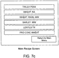
Figure 7c . This screen presents the user with a list of pre-programmed "recipes" or settings that are required for treatment application for different seed types. Preprogramming such settings allows the user to quickly return to needed settings. - When the user selects one of the recipes on the Main Recipe Screen, the user is presented with a Recipe Setting Screen for the particular seed type, an example of which is shown at
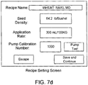
Figure 7d . This Recipe Setting Screen contains the information necessary for the proper control of theconveyor motor 22 andpump 46. The user can enter a recipe name (a keypad pops up upon selecting this item) and must enter a seed density, which seed density can be determined using a half-litre cup and scale as indicated above. As stated above, this seed density is used by the controller to convert the volume flow of theconveyor 16 to a mass flow. The application rate must also be entered by the user and is normally found on the treatment product label, expressed in mL/100kg. The pump calibration number defaults to 1000 which is 100%, but this can be changed manually or through a pump test. - If the user presses the pump test button on the Recipe Setting Screen, they are presented with the Pump Calibration Screen shown at
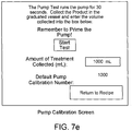
Figure 7e . This screen is used to account for different seed treatment fluid viscosities, as fluids of different viscosities will move through thepump 46 differently. During the pump test, thepump 46 is operated for 30 seconds, the liquid is collected, and the volume is measured. The user enters the volume at the "Amount of Treatment Collected" line, and the controller calculates the volume pumped per revolution of themotor 22. - Returning to the Main Screen, the user can then select the "Operation" button and will be presented with the Operation Screen shown at
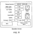
Figure 7f . This screen is displayed prior to and during operation of theapparatus 10. Once "Start" has been selected, theapparatus 10 will begin running and the "Start" button will disappear and be replaced on thetouchscreen 52 with a red "Stop" button - pushing the "Stop" button will cause themotor 22 and pump 46 to shut off. Operation of theapparatus 10 will proceed on the basis of the selected seed-specific recipe and application rate (shown as bushels/minute and lbs/minute on the screen), both of which are displayed on the screen. The controller calculates how fast to turn theconveyor 16 based on the bushels required per minute, and uses the seed density to convert this volume to a mass flow through theapparatus 10. The mass flow is required as the application rate of treatment entered in the recipe is based on mL/100kg. From this information, the controller then calculates how fast to turn thepump 46 to get the calculated optimal application rate of treatment. The controller uses proportional control to operate thepump 46 at the correct speed relative to theconveyor 16 speed; in this way the application rate is as desired regardless of the seed flow selected, and this control reduces the amount of calibration necessary when changing products and flow rates. - As can be further seen in
Figure 7f , the controller allows the user to select a certain batch size ofseed 36 to be treated. By pressing the square to the right of the "Batch Size" label on thetouchscreen 52, a further screen appears allowing the user to enter a seed amount in lbs. If a batch amount is entered, then the "lbs Treated" line is activated and tracks the amount of seed left to be treated in the batch. In this batch mode of operation, the unit will run until the set-point is reached and then thepump 46 andconveyor 16 will be shut off. If "0" is chosen as the batch size, the unit will run continuously until the "Stop" button is pressed on thetouchscreen 52, and the "lbs Treated" line will display the seed that has been treated as the unit is running. The conveyor rpm and pump rpm are also displayed, and will display "0" until the unit is running. - From the Main Screen, the user can also select the "Totals" button, which will display a Totals Screen as shown in
Figure 7g . This screen tracks the treatment in progress, with options to track and save data for two batches and the treatment used. The screen also displays the lifetime treatment total of seed for the unit. From the Main Screen, the user can also select the "Setup/Maintenance" button, which can display a screen (not shown) for changing units from Imperial to Metric or any number of other settings. - As can be readily seen, then, the apparatus of the present invention present significant advantages over the prior art. For example, the apparatus provides for metering based on positive displacement instead of an inaccurate screw-type auger, with a low profile due to a horizontally disposed conveyor (both the belt-type conveyor and circular conveyor) so it can fit under common hopper-bottom bins. Also, the apparatus and methods according to the present invention incorporate a seed density determination to provide more accurate treatment application. Other advantages would be obvious to those skilled in the art.
- The foregoing is considered as illustrative only of the principles of the invention. Thus, while certain aspects and embodiments of the invention have been described, these have been presented by way of example only and arc not intended to limit the scope of the invention. Indeed, the invention described herein may be embodied in a variety of other forms without departing from the scope of the invention, which invention is defined solely by the claims below.
Claims (14)
- A seed treatment apparatus (10) comprising: a housing (12, 12a) having an inner surface (14); a conveyor (16, 16a) generally horizontally disposed within the housing (12, 12a), the conveyor (16, 16a) having spaced apart first (18, 18a) and second (20, 20a) ends and a conveyor drive mechanism (22); a conveyor intake (24, 24a) adjacent the first end (18, 18a) for receiving seed (36); a conveyor outlet (26, 26a) adjacent the second end (20) for discharging the seed (36); a seed treatment applicator (34) adjacent the conveyor outlet (26, 26a) for receiving the discharged seed (36) and applying seed treatment (38) to the seed (36); and a seed treatment source (40) in fluid communication with the seed treatment applicator (34) for providing the seed treatment (38); characterized in that the apparatus (10) further comprises a plurality of cleats (28, 28a) each having opposed first and second edges (30 and 32), the cleats (28, 28a) mounted at their first edges (30) on an outward surface of the conveyor (16, 16a) at regular spaced apart intervals, the second edges (32) of the cleats (28, 28a) extending toward the inner surface (14) of the housing (12, 12a), and the apparatus (10) further comprises a scraper (44) extending downwardly from the inner surface (14) of the housing (12, 12a) adjacent the intake (24), the scraper (44) having a length generally equal to a distance between the inner surface (14) of the housing (12, 12a) and the second edges (32) of the cleats (28, 28a) and a width generally equal to the cleats (28, 28a), such that the outward surface and the scraper (44) and the cleats (28, 28a) collectively define a series of cuboid voids for receiving and transporting determinable volumes of the seed (36), such that when the cleats (28, 28a) pass by the scraper (44) the scraper (44) levels off the received seed (36) so that the received seed (36) is generally flush with the second edges (32) of the cleats (28, 28a) thereby ensuring consistent seed volumes in each cuboid void.
- The apparatus (10) of Claim 1 wherein the housing (12, 12a) comprises the conveyor intake (24, 24a) and the conveyor outlet (26, 26a).
- The apparatus (10) of Claim 1 wherein the housing (12, 12a) contains the seed treatment applicator (34) and comprises a treated seed outlet (42).
- The apparatus (10) of Claim 1 wherein the scraper (44) is a brush.
- The apparatus (10) of Claim 1 wherein the conveyor (16, 16a) is a continuous belt conveyor (16).
- The apparatus (10) of Claim 1 wherein the conveyor (16, 16a) is a circular conveyor (16a).
- The apparatus (10) of Claim 1 wherein the seed treatment applicator (34) comprises a peristaltic pump (46) and spray nozzles (48).
- The apparatus (10) of Claim 1 further comprising a controller (50) for controlling the conveyor drive mechanism (22) and the seed treatment applicator (34).
- The apparatus (10) of Claim 8 wherein the controller (50) comprises a programmable logic controller, a data storage, a user interface, and a display.
- The apparatus (10) of Claim 9 wherein the user interface and the display are collectively a touchscreen monitor (52).
- The apparatus (10) of Claim 1 further comprising a channeling collar (54) mounted on the conveyor intake (24, 24a) for directing the seed (36) toward the conveyor intake (24, 24a).
- The apparatus (10) of Claim 11 wherein the channeling collar (54) is upwardly biased so as to sealingly engage with a source of the seed (36).
- The apparatus (10) of Claim 1 further comprising an extensible support (56) on the housing (12, 12a) for selectively elevating the second end (20, 20a) of the conveyor (16, 16a).
- The apparatus (10) of Claim 1 further comprising at least one ground-engaging wheel (58) to enable relocation of the apparatus (10).
Priority Applications (1)
| Application Number | Priority Date | Filing Date | Title |
|---|---|---|---|
| PL12880924T PL2869686T3 (en) | 2012-07-09 | 2012-07-09 | Low profile seed treater with metering functionality |
Applications Claiming Priority (1)
| Application Number | Priority Date | Filing Date | Title |
|---|---|---|---|
| PCT/CA2012/000641 WO2014008571A1 (en) | 2012-07-09 | 2012-07-09 | Low profile seed treater with metering functionality |
Publications (3)
| Publication Number | Publication Date |
|---|---|
| EP2869686A1 EP2869686A1 (en) | 2015-05-13 |
| EP2869686A4 EP2869686A4 (en) | 2016-03-02 |
| EP2869686B1 true EP2869686B1 (en) | 2019-05-22 |
Family
ID=49915275
Family Applications (1)
| Application Number | Title | Priority Date | Filing Date |
|---|---|---|---|
| EP12880924.1A Active EP2869686B1 (en) | 2012-07-09 | 2012-07-09 | Low profile seed treater with metering functionality |
Country Status (12)
| Country | Link |
|---|---|
| US (1) | US10631453B2 (en) |
| EP (1) | EP2869686B1 (en) |
| AP (1) | AP2014008167A0 (en) |
| AU (2) | AU2012385439B2 (en) |
| BR (1) | BR112015000343B1 (en) |
| CA (1) | CA2877860C (en) |
| EA (1) | EA030350B8 (en) |
| MX (1) | MX365400B (en) |
| PL (1) | PL2869686T3 (en) |
| UA (1) | UA116353C2 (en) |
| WO (1) | WO2014008571A1 (en) |
| ZA (1) | ZA201409326B (en) |
Cited By (1)
| Publication number | Priority date | Publication date | Assignee | Title |
|---|---|---|---|---|
| CN111003415A (en) * | 2019-11-22 | 2020-04-14 | 丁洁纯 | Snake-shaped conveyor suitable for narrow environment |
Families Citing this family (12)
| Publication number | Priority date | Publication date | Assignee | Title |
|---|---|---|---|---|
| US10918009B2 (en) | 2013-02-15 | 2021-02-16 | Bayer Cropscience Inc. | Rotatable apparatus for metering and treating agricultural granules |
| JP6398997B2 (en) * | 2014-02-03 | 2018-10-03 | 宇部興産株式会社 | Oxynitride phosphor powder and method for producing the same |
| US9730377B2 (en) * | 2015-06-26 | 2017-08-15 | Cnh Industrial Canada, Ltd. | Planter with on-board seed treatment |
| CN105083934A (en) * | 2015-07-03 | 2015-11-25 | 广东工业大学 | Coin feeding device |
| DE102016214553A1 (en) * | 2016-08-05 | 2018-02-08 | Deere & Company | Arrangement for detecting the amount of material in a reservoir of a machine for applying material to a field |
| US10582655B2 (en) | 2017-08-23 | 2020-03-10 | Cnh Industrial Canada, Ltd. | System and method for spraying fluid onto seeds dispensed from a planter |
| US11357160B2 (en) * | 2017-11-27 | 2022-06-14 | Ag Growth International Inc. | Automatic calibration of seed treater metering system |
| WO2019152704A1 (en) * | 2018-02-05 | 2019-08-08 | Forsyth Daniel L | Coating flowable contact-tolerant granules, including seeds |
| RU193591U1 (en) * | 2019-04-24 | 2019-11-06 | Федеральное государственное бюджетное образовательное учреждение высшего образования "Ульяновский государственный аграрный университет имени П.А. Столыпина" | DEVICE FOR GRAIN MANAGEMENT AND LOADING |
| RU191544U1 (en) * | 2019-04-24 | 2019-08-12 | Федеральное государственное бюджетное образовательное учреждение высшего образования "Ульяновский государственный аграрный университет имени П.А. Столыпина" | DEVICE FOR GRAIN MANAGEMENT AND LOADING |
| US11758834B2 (en) | 2019-07-29 | 2023-09-19 | KSi Conveyor, Inc. | Method for mixing a stream of particulate material by inducing backflow within an inclined belt conveyor |
| CN112428473A (en) * | 2020-11-24 | 2021-03-02 | 颍上县龙裕扬工贸有限公司 | Automatic plastic products processing of batch business turn over material uses raw materials drying device |
Family Cites Families (14)
| Publication number | Priority date | Publication date | Assignee | Title |
|---|---|---|---|---|
| GB649436A (en) * | 1947-11-24 | 1951-01-24 | Johannes Jacobus De Villiers S | Improvements in or relating to seed planting implements |
| US3765125A (en) * | 1972-07-03 | 1973-10-16 | R Amburn | Apparatus for treating seeds |
| US4023525A (en) | 1976-08-04 | 1977-05-17 | Gustafson, Inc. | Seed treater |
| GB1568514A (en) | 1976-10-19 | 1980-05-29 | Debreceni Mezogazasagi Gepgyar | Process and an apparatus for the dressing and/or chemical treatment of tuberous seed crops particularly seedpotatoes |
| US4208135A (en) * | 1978-11-01 | 1980-06-17 | Bastiao Manuel J | Mixing device |
| FR2593663B1 (en) | 1986-01-31 | 1989-04-14 | Sip Condi Film Sa | PROCESS FOR REGULATING TREATMENT OF SEEDS AND THE LIKE, MEANS FOR CARRYING OUT SAID METHOD AND TREATMENT FACILITIES PROVIDED WITH SAID MEANS |
| US4993316A (en) * | 1988-05-09 | 1991-02-19 | Agrichem, Inc. | Seed grain conditioning apparatus |
| CA2196001C (en) | 1997-01-27 | 2002-12-17 | Robert J. Graham | G3 seed treater |
| GB9914795D0 (en) * | 1999-06-25 | 1999-08-25 | Perry Of Oakley Limited | Application systems |
| CA2333834A1 (en) | 2001-02-05 | 2002-08-05 | Blaine Muhr | Seed inoculation system |
| EP1285562A1 (en) | 2001-08-21 | 2003-02-26 | Ion Beam Applications S.A. | Method and installation for irradiating bulk material |
| US7869902B2 (en) * | 2007-11-13 | 2011-01-11 | Pioneer Hi-Bred International, Inc. | Intelligent seed treatment system and method |
| US8258951B2 (en) * | 2008-03-14 | 2012-09-04 | The Invention Science Fund I, Llc | Method and system for correlating external data to a plant with an electronic tag |
| WO2011017252A1 (en) | 2009-08-03 | 2011-02-10 | Bayer Cropscience Lp | Seed treatment apparatus |
-
2012
- 2012-07-09 MX MX2015000299A patent/MX365400B/en active IP Right Grant
- 2012-07-09 AP AP2014008167A patent/AP2014008167A0/en unknown
- 2012-07-09 AU AU2012385439A patent/AU2012385439B2/en active Active
- 2012-07-09 EP EP12880924.1A patent/EP2869686B1/en active Active
- 2012-07-09 US US14/413,331 patent/US10631453B2/en active Active
- 2012-07-09 UA UAA201500956A patent/UA116353C2/en unknown
- 2012-07-09 CA CA2877860A patent/CA2877860C/en active Active
- 2012-07-09 WO PCT/CA2012/000641 patent/WO2014008571A1/en active Application Filing
- 2012-07-09 BR BR112015000343-5A patent/BR112015000343B1/en active IP Right Grant
- 2012-07-09 PL PL12880924T patent/PL2869686T3/en unknown
- 2012-07-09 EA EA201590104A patent/EA030350B8/en not_active IP Right Cessation
-
2014
- 2014-12-18 ZA ZA2014/09326A patent/ZA201409326B/en unknown
-
2018
- 2018-06-22 AU AU2018204535A patent/AU2018204535A1/en not_active Abandoned
Non-Patent Citations (1)
| Title |
|---|
| None * |
Cited By (2)
| Publication number | Priority date | Publication date | Assignee | Title |
|---|---|---|---|---|
| CN111003415A (en) * | 2019-11-22 | 2020-04-14 | 丁洁纯 | Snake-shaped conveyor suitable for narrow environment |
| CN111003415B (en) * | 2019-11-22 | 2021-04-27 | 双鸭山市金诺恒业机械制造有限公司 | Snake-shaped conveyor suitable for narrow environment |
Also Published As
| Publication number | Publication date |
|---|---|
| AU2012385439A1 (en) | 2015-01-29 |
| EA030350B1 (en) | 2018-07-31 |
| EA030350B8 (en) | 2018-10-31 |
| EA201590104A1 (en) | 2015-10-30 |
| BR112015000343A2 (en) | 2017-06-27 |
| BR112015000343B1 (en) | 2019-10-29 |
| US20150359164A1 (en) | 2015-12-17 |
| EP2869686A4 (en) | 2016-03-02 |
| ZA201409326B (en) | 2016-09-28 |
| UA116353C2 (en) | 2018-03-12 |
| AP2014008167A0 (en) | 2014-12-31 |
| WO2014008571A1 (en) | 2014-01-16 |
| CA2877860C (en) | 2018-05-01 |
| MX2015000299A (en) | 2015-07-23 |
| PL2869686T3 (en) | 2019-11-29 |
| AU2018204535A1 (en) | 2018-07-12 |
| EP2869686A1 (en) | 2015-05-13 |
| US10631453B2 (en) | 2020-04-28 |
| AU2012385439B2 (en) | 2018-04-05 |
| MX365400B (en) | 2019-05-31 |
| CA2877860A1 (en) | 2014-01-16 |
Similar Documents
| Publication | Publication Date | Title |
|---|---|---|
| EP2869686B1 (en) | Low profile seed treater with metering functionality | |
| US11291154B2 (en) | Seed treatment apparatus | |
| US10813275B2 (en) | System and method for independent calibration of meter rollers | |
| US8408478B2 (en) | Product distribution apparatus with system and method of automatic meter calibration | |
| US7240807B2 (en) | Method and apparatus for administering micro-ingredient feed additives to animal feed rations | |
| US8683930B2 (en) | Side mounted air seeder product container | |
| US20160302352A1 (en) | High redundancy seed coating apparatus and method | |
| EP1625787B1 (en) | Apparatus for separating and mixing feed for livestock | |
| EP2698064B1 (en) | Device for providing dough products with a topping material | |
| US20200245541A1 (en) | Operation of an agricultural agitating system | |
| US11665995B2 (en) | Agitation control system | |
| WO2005124295A1 (en) | Apparatus and method for substantially continous delivery of a substantially constant weight of material per unit of time from a bulk storage location and for weighing, blending, and mixing conveyable materials | |
| AU2014218344A1 (en) | Rotatable apparatus for metering and treating agricultural granules | |
| WO2019088823A1 (en) | A dispensing apparatus | |
| CA2755585C (en) | Side mounted air seeder product container | |
| KR20210050815A (en) | Quantitative supplier for agricultural chemical powder | |
| Field et al. | Machinery Calibration | |
| CN108077976A (en) | Paint finishing after thousand classification of one kind | |
| TWM552742U (en) | Quantitative dispensing device for food material | |
| PL219468B1 (en) | Method and a device for dispensing seeds and mortars, especially in the seed dressers | |
| PL202853B1 (en) | Method of and apparatus for dispensing liquids and seeds especially for use in seed dressing equipment |
Legal Events
| Date | Code | Title | Description |
|---|---|---|---|
| PUAI | Public reference made under article 153(3) epc to a published international application that has entered the european phase |
Free format text: ORIGINAL CODE: 0009012 |
|
| 17P | Request for examination filed |
Effective date: 20150209 |
|
| AK | Designated contracting states |
Kind code of ref document: A1 Designated state(s): AL AT BE BG CH CY CZ DE DK EE ES FI FR GB GR HR HU IE IS IT LI LT LU LV MC MK MT NL NO PL PT RO RS SE SI SK SM TR |
|
| AX | Request for extension of the european patent |
Extension state: BA ME |
|
| DAX | Request for extension of the european patent (deleted) | ||
| RA4 | Supplementary search report drawn up and despatched (corrected) |
Effective date: 20160203 |
|
| RIC1 | Information provided on ipc code assigned before grant |
Ipc: A01C 1/06 20060101AFI20160128BHEP Ipc: B65G 15/00 20060101ALI20160128BHEP Ipc: B65G 15/44 20060101ALI20160128BHEP Ipc: A01C 1/00 20060101ALI20160128BHEP Ipc: B65G 15/42 20060101ALI20160128BHEP |
|
| STAA | Information on the status of an ep patent application or granted ep patent |
Free format text: STATUS: EXAMINATION IS IN PROGRESS |
|
| 17Q | First examination report despatched |
Effective date: 20180117 |
|
| GRAP | Despatch of communication of intention to grant a patent |
Free format text: ORIGINAL CODE: EPIDOSNIGR1 |
|
| STAA | Information on the status of an ep patent application or granted ep patent |
Free format text: STATUS: GRANT OF PATENT IS INTENDED |
|
| INTG | Intention to grant announced |
Effective date: 20180822 |
|
| GRAS | Grant fee paid |
Free format text: ORIGINAL CODE: EPIDOSNIGR3 |
|
| GRAA | (expected) grant |
Free format text: ORIGINAL CODE: 0009210 |
|
| STAA | Information on the status of an ep patent application or granted ep patent |
Free format text: STATUS: THE PATENT HAS BEEN GRANTED |
|
| AK | Designated contracting states |
Kind code of ref document: B1 Designated state(s): AL AT BE BG CH CY CZ DE DK EE ES FI FR GB GR HR HU IE IS IT LI LT LU LV MC MK MT NL NO PL PT RO RS SE SI SK SM TR |
|
| REG | Reference to a national code |
Ref country code: GB Ref legal event code: FG4D |
|
| REG | Reference to a national code |
Ref country code: CH Ref legal event code: EP |
|
| REG | Reference to a national code |
Ref country code: IE Ref legal event code: FG4D |
|
| REG | Reference to a national code |
Ref country code: DE Ref legal event code: R096 Ref document number: 602012060503 Country of ref document: DE |
|
| REG | Reference to a national code |
Ref country code: AT Ref legal event code: REF Ref document number: 1134933 Country of ref document: AT Kind code of ref document: T Effective date: 20190615 |
|
| REG | Reference to a national code |
Ref country code: NL Ref legal event code: MP Effective date: 20190522 |
|
| REG | Reference to a national code |
Ref country code: LT Ref legal event code: MG4D |
|
| PG25 | Lapsed in a contracting state [announced via postgrant information from national office to epo] |
Ref country code: ES Free format text: LAPSE BECAUSE OF FAILURE TO SUBMIT A TRANSLATION OF THE DESCRIPTION OR TO PAY THE FEE WITHIN THE PRESCRIBED TIME-LIMIT Effective date: 20190522 Ref country code: NL Free format text: LAPSE BECAUSE OF FAILURE TO SUBMIT A TRANSLATION OF THE DESCRIPTION OR TO PAY THE FEE WITHIN THE PRESCRIBED TIME-LIMIT Effective date: 20190522 Ref country code: LT Free format text: LAPSE BECAUSE OF FAILURE TO SUBMIT A TRANSLATION OF THE DESCRIPTION OR TO PAY THE FEE WITHIN THE PRESCRIBED TIME-LIMIT Effective date: 20190522 Ref country code: HR Free format text: LAPSE BECAUSE OF FAILURE TO SUBMIT A TRANSLATION OF THE DESCRIPTION OR TO PAY THE FEE WITHIN THE PRESCRIBED TIME-LIMIT Effective date: 20190522 Ref country code: NO Free format text: LAPSE BECAUSE OF FAILURE TO SUBMIT A TRANSLATION OF THE DESCRIPTION OR TO PAY THE FEE WITHIN THE PRESCRIBED TIME-LIMIT Effective date: 20190822 Ref country code: FI Free format text: LAPSE BECAUSE OF FAILURE TO SUBMIT A TRANSLATION OF THE DESCRIPTION OR TO PAY THE FEE WITHIN THE PRESCRIBED TIME-LIMIT Effective date: 20190522 Ref country code: PT Free format text: LAPSE BECAUSE OF FAILURE TO SUBMIT A TRANSLATION OF THE DESCRIPTION OR TO PAY THE FEE WITHIN THE PRESCRIBED TIME-LIMIT Effective date: 20190922 Ref country code: SE Free format text: LAPSE BECAUSE OF FAILURE TO SUBMIT A TRANSLATION OF THE DESCRIPTION OR TO PAY THE FEE WITHIN THE PRESCRIBED TIME-LIMIT Effective date: 20190522 Ref country code: AL Free format text: LAPSE BECAUSE OF FAILURE TO SUBMIT A TRANSLATION OF THE DESCRIPTION OR TO PAY THE FEE WITHIN THE PRESCRIBED TIME-LIMIT Effective date: 20190522 |
|
| PG25 | Lapsed in a contracting state [announced via postgrant information from national office to epo] |
Ref country code: LV Free format text: LAPSE BECAUSE OF FAILURE TO SUBMIT A TRANSLATION OF THE DESCRIPTION OR TO PAY THE FEE WITHIN THE PRESCRIBED TIME-LIMIT Effective date: 20190522 Ref country code: GR Free format text: LAPSE BECAUSE OF FAILURE TO SUBMIT A TRANSLATION OF THE DESCRIPTION OR TO PAY THE FEE WITHIN THE PRESCRIBED TIME-LIMIT Effective date: 20190823 Ref country code: BG Free format text: LAPSE BECAUSE OF FAILURE TO SUBMIT A TRANSLATION OF THE DESCRIPTION OR TO PAY THE FEE WITHIN THE PRESCRIBED TIME-LIMIT Effective date: 20190822 Ref country code: RS Free format text: LAPSE BECAUSE OF FAILURE TO SUBMIT A TRANSLATION OF THE DESCRIPTION OR TO PAY THE FEE WITHIN THE PRESCRIBED TIME-LIMIT Effective date: 20190522 |
|
| PG25 | Lapsed in a contracting state [announced via postgrant information from national office to epo] |
Ref country code: CZ Free format text: LAPSE BECAUSE OF FAILURE TO SUBMIT A TRANSLATION OF THE DESCRIPTION OR TO PAY THE FEE WITHIN THE PRESCRIBED TIME-LIMIT Effective date: 20190522 Ref country code: RO Free format text: LAPSE BECAUSE OF FAILURE TO SUBMIT A TRANSLATION OF THE DESCRIPTION OR TO PAY THE FEE WITHIN THE PRESCRIBED TIME-LIMIT Effective date: 20190522 Ref country code: SK Free format text: LAPSE BECAUSE OF FAILURE TO SUBMIT A TRANSLATION OF THE DESCRIPTION OR TO PAY THE FEE WITHIN THE PRESCRIBED TIME-LIMIT Effective date: 20190522 Ref country code: EE Free format text: LAPSE BECAUSE OF FAILURE TO SUBMIT A TRANSLATION OF THE DESCRIPTION OR TO PAY THE FEE WITHIN THE PRESCRIBED TIME-LIMIT Effective date: 20190522 Ref country code: DK Free format text: LAPSE BECAUSE OF FAILURE TO SUBMIT A TRANSLATION OF THE DESCRIPTION OR TO PAY THE FEE WITHIN THE PRESCRIBED TIME-LIMIT Effective date: 20190522 |
|
| REG | Reference to a national code |
Ref country code: DE Ref legal event code: R097 Ref document number: 602012060503 Country of ref document: DE |
|
| PG25 | Lapsed in a contracting state [announced via postgrant information from national office to epo] |
Ref country code: SM Free format text: LAPSE BECAUSE OF FAILURE TO SUBMIT A TRANSLATION OF THE DESCRIPTION OR TO PAY THE FEE WITHIN THE PRESCRIBED TIME-LIMIT Effective date: 20190522 Ref country code: MC Free format text: LAPSE BECAUSE OF FAILURE TO SUBMIT A TRANSLATION OF THE DESCRIPTION OR TO PAY THE FEE WITHIN THE PRESCRIBED TIME-LIMIT Effective date: 20190522 |
|
| REG | Reference to a national code |
Ref country code: CH Ref legal event code: PL |
|
| PLBE | No opposition filed within time limit |
Free format text: ORIGINAL CODE: 0009261 |
|
| STAA | Information on the status of an ep patent application or granted ep patent |
Free format text: STATUS: NO OPPOSITION FILED WITHIN TIME LIMIT |
|
| PG25 | Lapsed in a contracting state [announced via postgrant information from national office to epo] |
Ref country code: TR Free format text: LAPSE BECAUSE OF FAILURE TO SUBMIT A TRANSLATION OF THE DESCRIPTION OR TO PAY THE FEE WITHIN THE PRESCRIBED TIME-LIMIT Effective date: 20190522 |
|
| REG | Reference to a national code |
Ref country code: BE Ref legal event code: MM Effective date: 20190731 |
|
| 26N | No opposition filed |
Effective date: 20200225 |
|
| PG25 | Lapsed in a contracting state [announced via postgrant information from national office to epo] |
Ref country code: LU Free format text: LAPSE BECAUSE OF NON-PAYMENT OF DUE FEES Effective date: 20190709 Ref country code: SI Free format text: LAPSE BECAUSE OF FAILURE TO SUBMIT A TRANSLATION OF THE DESCRIPTION OR TO PAY THE FEE WITHIN THE PRESCRIBED TIME-LIMIT Effective date: 20190522 Ref country code: LI Free format text: LAPSE BECAUSE OF NON-PAYMENT OF DUE FEES Effective date: 20190731 Ref country code: CH Free format text: LAPSE BECAUSE OF NON-PAYMENT OF DUE FEES Effective date: 20190731 Ref country code: BE Free format text: LAPSE BECAUSE OF NON-PAYMENT OF DUE FEES Effective date: 20190731 |
|
| REG | Reference to a national code |
Ref country code: AT Ref legal event code: UEP Ref document number: 1134933 Country of ref document: AT Kind code of ref document: T Effective date: 20190522 |
|
| PG25 | Lapsed in a contracting state [announced via postgrant information from national office to epo] |
Ref country code: IE Free format text: LAPSE BECAUSE OF NON-PAYMENT OF DUE FEES Effective date: 20190709 |
|
| PG25 | Lapsed in a contracting state [announced via postgrant information from national office to epo] |
Ref country code: CY Free format text: LAPSE BECAUSE OF FAILURE TO SUBMIT A TRANSLATION OF THE DESCRIPTION OR TO PAY THE FEE WITHIN THE PRESCRIBED TIME-LIMIT Effective date: 20190522 |
|
| PG25 | Lapsed in a contracting state [announced via postgrant information from national office to epo] |
Ref country code: IS Free format text: LAPSE BECAUSE OF FAILURE TO SUBMIT A TRANSLATION OF THE DESCRIPTION OR TO PAY THE FEE WITHIN THE PRESCRIBED TIME-LIMIT Effective date: 20190922 |
|
| PG25 | Lapsed in a contracting state [announced via postgrant information from national office to epo] |
Ref country code: MT Free format text: LAPSE BECAUSE OF FAILURE TO SUBMIT A TRANSLATION OF THE DESCRIPTION OR TO PAY THE FEE WITHIN THE PRESCRIBED TIME-LIMIT Effective date: 20190522 Ref country code: HU Free format text: LAPSE BECAUSE OF FAILURE TO SUBMIT A TRANSLATION OF THE DESCRIPTION OR TO PAY THE FEE WITHIN THE PRESCRIBED TIME-LIMIT; INVALID AB INITIO Effective date: 20120709 |
|
| PG25 | Lapsed in a contracting state [announced via postgrant information from national office to epo] |
Ref country code: MK Free format text: LAPSE BECAUSE OF FAILURE TO SUBMIT A TRANSLATION OF THE DESCRIPTION OR TO PAY THE FEE WITHIN THE PRESCRIBED TIME-LIMIT Effective date: 20190522 |
|
| PGFP | Annual fee paid to national office [announced via postgrant information from national office to epo] |
Ref country code: FR Payment date: 20230622 Year of fee payment: 12 |
|
| PGFP | Annual fee paid to national office [announced via postgrant information from national office to epo] |
Ref country code: PL Payment date: 20230627 Year of fee payment: 12 |
|
| PGFP | Annual fee paid to national office [announced via postgrant information from national office to epo] |
Ref country code: IT Payment date: 20230627 Year of fee payment: 12 Ref country code: GB Payment date: 20230622 Year of fee payment: 12 Ref country code: AT Payment date: 20230626 Year of fee payment: 12 |
|
| PGFP | Annual fee paid to national office [announced via postgrant information from national office to epo] |
Ref country code: DE Payment date: 20230620 Year of fee payment: 12 |