EP2869023B1 - Bildverarbeitungsvorrichtung, Bildverarbeitungsverfahren und entsprechendes Computerprogramm - Google Patents
Bildverarbeitungsvorrichtung, Bildverarbeitungsverfahren und entsprechendes Computerprogramm Download PDFInfo
- Publication number
- EP2869023B1 EP2869023B1 EP14003573.4A EP14003573A EP2869023B1 EP 2869023 B1 EP2869023 B1 EP 2869023B1 EP 14003573 A EP14003573 A EP 14003573A EP 2869023 B1 EP2869023 B1 EP 2869023B1
- Authority
- EP
- European Patent Office
- Prior art keywords
- parameter
- pattern
- exposure amount
- image
- image capturing
- Prior art date
- Legal status (The legal status is an assumption and is not a legal conclusion. Google has not performed a legal analysis and makes no representation as to the accuracy of the status listed.)
- Active
Links
- 238000012545 processing Methods 0.000 title claims description 126
- 238000004590 computer program Methods 0.000 title claims description 13
- 238000003672 processing method Methods 0.000 title claims description 3
- 238000005259 measurement Methods 0.000 claims description 64
- 230000007423 decrease Effects 0.000 claims description 26
- 229920006395 saturated elastomer Polymers 0.000 claims description 11
- 238000009795 derivation Methods 0.000 claims 2
- 238000000034 method Methods 0.000 description 107
- 230000003287 optical effect Effects 0.000 description 48
- 230000008859 change Effects 0.000 description 20
- 238000004364 calculation method Methods 0.000 description 19
- 230000008569 process Effects 0.000 description 17
- 238000012937 correction Methods 0.000 description 14
- 230000006870 function Effects 0.000 description 12
- 238000010586 diagram Methods 0.000 description 11
- 238000005286 illumination Methods 0.000 description 10
- 238000001514 detection method Methods 0.000 description 6
- 230000004048 modification Effects 0.000 description 5
- 238000012986 modification Methods 0.000 description 5
- 238000002834 transmittance Methods 0.000 description 5
- 229910052736 halogen Inorganic materials 0.000 description 4
- 150000002367 halogens Chemical class 0.000 description 4
- 230000007246 mechanism Effects 0.000 description 4
- 239000002131 composite material Substances 0.000 description 3
- 241000276498 Pollachius virens Species 0.000 description 2
- 230000005540 biological transmission Effects 0.000 description 2
- 230000015556 catabolic process Effects 0.000 description 2
- 238000006243 chemical reaction Methods 0.000 description 2
- 238000006731 degradation reaction Methods 0.000 description 2
- 238000009792 diffusion process Methods 0.000 description 2
- 239000002184 metal Substances 0.000 description 2
- 230000002035 prolonged effect Effects 0.000 description 2
- 230000009467 reduction Effects 0.000 description 2
- 230000000694 effects Effects 0.000 description 1
- 239000004973 liquid crystal related substance Substances 0.000 description 1
- 238000000691 measurement method Methods 0.000 description 1
- 230000002093 peripheral effect Effects 0.000 description 1
- 230000010363 phase shift Effects 0.000 description 1
- 238000013139 quantization Methods 0.000 description 1
- 238000005070 sampling Methods 0.000 description 1
- 238000009738 saturating Methods 0.000 description 1
Images


Classifications
-
- G—PHYSICS
- G01—MEASURING; TESTING
- G01B—MEASURING LENGTH, THICKNESS OR SIMILAR LINEAR DIMENSIONS; MEASURING ANGLES; MEASURING AREAS; MEASURING IRREGULARITIES OF SURFACES OR CONTOURS
- G01B21/00—Measuring arrangements or details thereof, where the measuring technique is not covered by the other groups of this subclass, unspecified or not relevant
- G01B21/02—Measuring arrangements or details thereof, where the measuring technique is not covered by the other groups of this subclass, unspecified or not relevant for measuring length, width, or thickness
- G01B21/04—Measuring arrangements or details thereof, where the measuring technique is not covered by the other groups of this subclass, unspecified or not relevant for measuring length, width, or thickness by measuring coordinates of points
- G01B21/047—Accessories, e.g. for positioning, for tool-setting, for measuring probes
-
- H—ELECTRICITY
- H04—ELECTRIC COMMUNICATION TECHNIQUE
- H04N—PICTORIAL COMMUNICATION, e.g. TELEVISION
- H04N23/00—Cameras or camera modules comprising electronic image sensors; Control thereof
- H04N23/70—Circuitry for compensating brightness variation in the scene
- H04N23/73—Circuitry for compensating brightness variation in the scene by influencing the exposure time
-
- G—PHYSICS
- G01—MEASURING; TESTING
- G01B—MEASURING LENGTH, THICKNESS OR SIMILAR LINEAR DIMENSIONS; MEASURING ANGLES; MEASURING AREAS; MEASURING IRREGULARITIES OF SURFACES OR CONTOURS
- G01B11/00—Measuring arrangements characterised by the use of optical techniques
- G01B11/02—Measuring arrangements characterised by the use of optical techniques for measuring length, width or thickness
- G01B11/06—Measuring arrangements characterised by the use of optical techniques for measuring length, width or thickness for measuring thickness ; e.g. of sheet material
- G01B11/0608—Height gauges
-
- G—PHYSICS
- G01—MEASURING; TESTING
- G01B—MEASURING LENGTH, THICKNESS OR SIMILAR LINEAR DIMENSIONS; MEASURING ANGLES; MEASURING AREAS; MEASURING IRREGULARITIES OF SURFACES OR CONTOURS
- G01B11/00—Measuring arrangements characterised by the use of optical techniques
- G01B11/24—Measuring arrangements characterised by the use of optical techniques for measuring contours or curvatures
- G01B11/25—Measuring arrangements characterised by the use of optical techniques for measuring contours or curvatures by projecting a pattern, e.g. one or more lines, moiré fringes on the object
Definitions
- the present invention relates to a technique for performing distance measurement with respect to a target object.
- the reflectance of the surface of a target object and the orientation in which the target object is placed vary.
- the image luminance gradation value of pattern light projected from the projection unit in a captured image changes variously.
- brightness adjustment of pattern light and exposure amount adjustment of the image capturing unit need to be performed appropriately. If these adjustments are improper, pattern light in a captured image is saturated or causes shadow detail loss, and the position of the pattern light cannot be specified. Also, if these adjustments are insufficient, the position of pattern light may be specified, but the position specifying accuracy drops.
- patent literature 1 Japanese Patent Laid-Open No. 2012-68176
- the maximum reflectance is determined based on the image luminance gradation value of an image captured after projecting uniform pattern light in advance, and the brightness of pattern light and the exposure amount of the image capturing unit are determined based on the reflectance.
- the exposure amount of an image capturing unit is adjusted using the histogram of the image luminance gradation value of an image captured after projecting an optical cutting line. More specifically, in the image luminance gradation value histogram, the difference between the first peak corresponding to an optical cutting line portion, and the second peak corresponding to background light generated by illumination light in a measurement environment is adjusted to be equal to or larger than a threshold. Further, the first peak is adjusted not to exceed a preset upper limit value.
- the brightness of pattern light and the exposure amount of the image capturing unit are determined based on the image luminance gradation value of not pattern light used to specify a position, but uniform pattern light.
- the influence of a decrease in the contrast of pattern light arising from, for example, a blur in the projection optical system or image capturing optical system that is generated in pattern light used to specify a position is not taken into account.
- the maximum reflectance and exposure amount are determined based on the maximum value of the image luminance gradation value.
- the invention disclosed in patent literature 2 effectively functions in a case in which the peak of the image luminance gradation value histogram by projection light and the peak of background light are clearly separated.
- the luminance of background light is high and is almost equal to the luminance of projection light, it is difficult to discriminate the peaks of the image luminance gradation value histograms of projection light and background light, and the invention may not effectively function.
- a recognition processing apparatus which estimates the positions and orientations of a plurality of piled target objects based on distance measurement results by a distance measurement apparatus configured to perform the above-described distance measurement.
- a system can be constructed, in which the robot can automatically pick piled target objects by outputting, to a robot control apparatus, the estimation results of the positions and orientations of target objects by the recognition processing apparatus.
- the distance from the apparatus to a target object changes depending on the height of the pile. If the distance from the apparatus to a target object changes, the illuminance of projection pattern light and the brightness of a captured image change. More specifically, the brightness of a captured image decreases in proportion to the square of the distance from the apparatus to a target object.
- light falloff at edges occurs in accordance with the position of a target object in a captured image and the position of the target object in the projection range, and the brightness of the captured image changes. That is, the captured image becomes brighter toward the center of the frame, and darker toward the edge. For example, the captured image becomes dark based on the cosine fourth-power law.
- the image luminance gradation value of pattern light projected from the projection unit in a captured image changes variously in accordance with the distance to a target object or the position in the captured image. If the captured image becomes dark, the influence of noise of an image capturing element increases, and the distance measurement accuracy decreases. The decrease in distance measurement accuracy decreases even the estimation accuracy of the position and orientation of a target object by the recognition processing apparatus.
- the picking system may cause a failure such as a failure in picking a target object by the robot.
- Patent literature 3 Japanese Patent Laid-Open No. 2000-292133
- Patent literature 4 Japanese Patent Laid-Open No. 2000-241131
- Patent literature 4 Japanese Patent Laid-Open No. 2000-241131
- the exposure amount of the entire frame is adjusted based on a rough distance.
- optimal exposure amount adjustment is not implemented for a target object placed at a specific position in the projection area.
- Patent literature 5 discloses adjusting a quantity of light that enters an image sensor such that the tone values of tone points adjacent to tone intersections are lower than a maximum tone value and a tone value of at least one tone point other than the tone points adjacent to tone intersections is equal to the maximum tone value.
- the present invention has been made to solve the above-described problems, and provides a technique for reliably specifying the position of pattern light at high accuracy.
- the present invention also provides a technique for performing distance measurement with respect to each target object at higher accuracy.
- the present invention in its first aspect provides an image processing apparatus as specified in claims 1 to 22.
- the present invention in its second aspect provides an image processing method as specified in claim 23.
- the present invention in its third aspect provides a computer program as specified in claim 24.
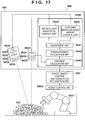
- the image processing apparatus includes a projection unit 30 which projects pattern light to a target object 5, an image capturing unit 20 which captures the target object 5 to which the pattern light has been projected, and an image processing unit 40 which controls the projection unit 30 and image capturing unit 20, and performs distance measurement with respect to the target object 5 based on a space encoding method.
- the projection unit 30 includes a light source 31, illumination optical system 32, display element 33, projection stop 34, and projection optical system 35.
- the light source 31 is, for example, one of various light emitting elements such as a halogen lamp and LED.
- the illumination optical system 32 is an optical system having a function of guiding light emitted by the light source 31 to the display element 33.
- an optical system suited to uniform the luminance such as Koehler illumination or a diffusion plate, is used.
- the display element 33 is an element having a function of spatially controlling the transmittance or reflectance of light traveling from the illumination optical system 32 in accordance with a supplied pattern.
- a transmission LCD, reflection LCOS, or DMD is used as for supply of a pattern to the display element 33.
- a plurality of types of patterns held in the projection unit 30 may be sequentially supplied to the display element 33.
- the projection optical system 35 is an optical system configured to form light (pattern light) guided from the display element 33 into an image at a specific position of the target object 5.
- the projection stop 34 is used to control the f-number of the projection optical system 35.
- the image capturing unit 20 includes an image capturing optical system 23, image capturing stop 22, and image capturing element 21.
- the image capturing optical system 23 is an optical system configured to image a specific position of the target object 5 on the image capturing element 21.
- the image capturing stop 22 is used to control the f-number of the image capturing optical system 23.
- the image capturing element 21 is, for example, one of various photoelectric conversion elements such as a CMOS sensor and CCD sensor. Note that an analog signal photoelectrically converted by the image capturing element 21 is sampled and quantized by a control unit (not shown) in the image capturing unit 20, and is converted into a digital image signal. Further, the control unit generates, from the digital image signal, an image (captured image) in which each pixel has a luminance gradation value (density value and pixel value). The control unit appropriately sends the captured image to a memory in the image capturing unit 20 or to the image processing unit 40.
- the image capturing unit 20 captures the target object 5 every time the projection unit 30 projects different pattern light. More specifically, the image capturing unit 20 and projection unit 30 operate synchronously, and the image capturing unit 20 can capture the image of the target object 5 to which each different pattern light has been projected.
- the image processing unit 40 includes an adjustment unit 41, bright/dark portion determination unit 42, pattern position specifying unit 43, distance measurement unit 44, pattern light brightness control unit 45, and captured image exposure amount control unit 46.
- the pattern position specifying unit 43 acquires an image captured by the image capturing unit 20, and specifies, from the acquired captured image, the position (pattern position) of pattern light in the captured image.
- the bright/dark portion determination unit 42 acquires an image captured by the image capturing unit 20, and performs bright/dark portion determination by using the luminance gradation value of each pixel constituting the acquired captured image, and a pattern position specified from the captured image by the pattern position specifying unit 43.
- the adjustment unit 41 determines parameters for controlling the bright/dark portion of an image to be captured next time by the image capturing unit 20.
- the "parameters for controlling the bright/dark portion of an image to be captured next time by the image capturing unit 20" include a parameter for the image capturing unit 20, and a parameter for the projection unit 30. Both or either of the parameters may be determined.
- the pattern light brightness control unit 45 controls the brightness of pattern light projected from the projection unit 30 in accordance with the parameter.
- the method of controlling the brightness of pattern light includes, for example, the following three methods.
- the first method is to control the emission luminance of the light source 31.
- a halogen lamp when the application voltage is increased, the emission luminance increases.
- an LED when a current to be supplied is increased, the emission luminance increases.
- the "parameter for the projection unit 30" is a parameter for controlling the emission luminance of the light source 31.
- the second method is to control the display gradation value of the display element 33.
- the display gradation value In the case of an LCD, when the display gradation value is increased, the transmittance increases, and pattern light becomes bright. In the case of an LCOS, when the display gradation value is increased, the reflectance increases, and pattern light becomes bright. In the case of a DMD, when the display gradation value is increased, the ON count per frame increases, and pattern light becomes bright.
- the "parameter for the projection unit 30" is a parameter for controlling the display gradation value of the display element 33.
- the third method is to control the projection stop 34.
- pattern light becomes bright.
- pattern light becomes dark.
- the "parameter for the projection unit 30" is a parameter for controlling the projection stop 34.
- the captured image exposure amount control unit 46 controls, in accordance with the parameter, an exposure amount at the time of image capturing by the image capturing unit 20, thereby controlling the luminance gradation value of a captured image.
- the method of controlling the exposure amount of the image capturing unit 20 includes, for example, the following two methods.
- the first method is to control the exposure time (shutter speed) of the image capturing element 21.
- the exposure time is prolonged, the luminance gradation value of a captured image increases.
- the exposure time is shortened, the luminance gradation value decreases.
- the "parameter for the image capturing unit 20" is a parameter for controlling the exposure time (shutter speed) of the image capturing element 21.
- the second method is to control the image capturing stop 22.
- the stop When the stop is opened, the luminance gradation value of a captured image increases. Conversely, when the stop is narrowed, the luminance gradation value of a captured image decreases.
- the "parameter for the image capturing unit 20" is a parameter for controlling the image capturing stop 22.
- the distance measurement unit 44 acquires an image captured by the image capturing unit 20 every time the projection unit 30 projects each of a plurality of types of pattern beams. Then, the distance measurement unit 44 measures a distance from the image capturing unit 20 (image capturing optical system 23) to the target object 5 by the triangulation principle using a space code decoded from the acquired captured image, and a pattern position specified by the pattern position specifying unit 43 for the acquired captured image.
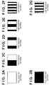
- Figs. 2A to 2G show projection patterns (pattern beams) in a 4-bit space encoding method.
- a projection pattern (full light-on pattern) shown in Fig. 2A and a projection pattern (full light-off pattern) shown in Fig. 2B are used to detect a shadow region and determine a bright/dark portion determination threshold.
- Projection patterns (positive patterns of 1 bit to 4 bits, respectively) in Figs. 2C to 2F are used to determine a space code.
- a projection pattern (4-bit negative pattern) in Fig. 2G is used to specify a pattern position at high accuracy together with the 4-bit positive pattern.
- the number of the space code is 16. Letting N be the number of bits of a projection pattern, the number of the space code becomes 2 N .
- the layout of bright and dark (white and black) portions of a pattern is determined based on a sign called a gray code.
- Fig. 3 shows a 4-bit gray code.
- the gray code is a pattern in which the Hamming distance between adjacent codes becomes 1. Even if the code determination is erroneous, the error can be minimized. Thus, the gray code is often used as a projection pattern in the space encoding method.
- the projection patterns of 1 bit to 4 bits shown in Figs. 2A to 2G are projected to a measurement target object, and the images of the measurement target object to which the respective projection patterns have been projected are captured. Based on the luminance gradation value of each pixel in each captured image obtained by the image capturing, it is determined whether the pixel is a portion irradiated with the bright portion of the projection pattern or a portion irradiated with the dark portion.
- the determination criterion for this determination can use the average value of the luminance gradation values of the full light-on pattern and full light-off pattern.
- the exit direction from the projection unit can be uniquely specified. For example, when a code "0110" is assigned to a given pixel, as shown in Fig. 3 , the gray code is 6. This gray code is converted into a space code of 4.
- the incident direction of light to the image capturing unit (more specifically, the principal point position of the image capturing unit) is determined from a pixel position in a captured image.
- the exit direction from the projection unit is specified.
- distance measurement with respect to a measurement target object becomes possible based on the triangulation principle. This is the distance measurement principle based on the space encoding method.
- the space encoding method can reduce an error by also using pattern light obtained by inverting the bright and dark portions of the projection pattern (in Figs. 2A to 2G , the 4-bit negative pattern in Fig. 2G ).
- the error reduction method will be explained subsequently with reference to Fig. 4 .
- a distance measurement error is generated by ⁇ Z.
- a negative pattern (in Figs. 2A to 2G , the 4-bit negative pattern in Fig. 2G ) obtained by inverting the bright and dark portions of the projection pattern (in Figs. 2A to 2G , the 4-bit positive pattern in Fig. 2F ) of the least significant bit (in Figs. 2A to 2G , the fourth bit) is further projected.
- An intersection point position between a luminance value waveform formed from the luminance values of respective pixels constituting the captured image of a target object to which the positive pattern has been projected, and a luminance value waveform formed from the luminance values of respective pixels constituting the captured image of the target object to which the negative pattern has been projected is set as a pattern position.
- This pattern position is used for the distance measurement.
- the intersection point position is a boundary position between adjacent space codes, and ideally does not have a width. In practice, the width is not 0 because quantization and sampling are executed when receiving a captured image as a digital image signal, and the luminance gradation value of the captured image contains image capturing element noise. However, the distance measurement error can be greatly reduced.
- the pattern position specifying unit 43 executes the processing of specifying the intersection point position. The method of reducing the distance measurement error has been explained.
- Fig. 5A is a graph in which the abscissa represents the image coordinate, and the ordinate represents the luminance gradation value.
- the image coordinate along the abscissa is a coordinate in a direction perpendicular to the direction of the stripe of a projection pattern in a captured image.
- a solid line indicates a luminance value waveform (positive pattern waveform) formed from the luminance values of respective pixels on one line in the direction perpendicular to the direction of the stripe of the positive pattern.
- a dotted line indicates a luminance value waveform (negative pattern waveform) formed from the luminance values of respective pixels on one line in the direction perpendicular to the direction of the stripe of the negative pattern.
- the respective waveforms are luminance value waveforms formed from the luminance values of respective pixels on the line at the same position in each captured image.
- Fig. 5B is an enlarged view showing the respective waveforms in a region surrounded by a thick solid line.
- PL is a luminance gradation value at a point on the positive pattern waveform out of two points (their image coordinates (values along the abscissa) are the same) on the left side from the intersection point position
- NL is a luminance gradation value at a point on the negative pattern waveform.
- PR is a luminance gradation value at a point on the positive pattern waveform out of two points (their image coordinates (values along the abscissa) are the same) on the right side from the intersection point position
- NR is a luminance gradation value at a point on the negative pattern waveform.
- DL is the absolute value of the difference (PL - NL) between the luminance gradation values
- DR is the absolute value of the difference (PR - NR) between the luminance gradation values.
- intersection point position C will be explained as a relative position using, as a reference, the image coordinate of the point of the luminance gradation value PL (point of the luminance gradation value NL).
- C DL/(DL + DR).
- Equation (2) reveals that the sub-pixel position estimation error ⁇ C can be reduced by increasing the denominator (DL or DR value as the difference between luminance gradation values).
- the difference DL (DR) between luminance gradation values increases in proportion to the luminance gradation value.
- a shot noise component out of the image capturing element noise ⁇ often exhibits a characteristic in which the shot noise component is proportional to the value of the square root of the luminance gradation value.
- the influence of the noise ⁇ is relatively reduced.
- To increase the luminance gradation value there are two methods: to increase the exposure amount in the image capturing unit 20, and to increase the brightness of pattern light.
- Both or either of these two methods can be executed.
- only the method of controlling the exposure amount in the image capturing unit 20 is executed.
- the exposure amount control method only the exposure time is controlled.
- control of the exposure amount can be implemented by a method other than control of the exposure time, and is not limited to a specific method.
- the control is applicable to even a method of controlling the image capturing stop 22, out of the exposure amount control method.
- the control is also applicable to control of the emission luminance of the light source 31, control of the display gradation value of the display element 33, and control of the projection stop 34, which is a method of controlling the brightness of pattern light.
- the method is not limited to a method of controlling only a single controlled variable, and a plurality of controlled variables can also be controlled simultaneously.
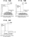
- N is the current exposure time.
- Fig. 6A shows the waveforms of the luminance gradation values of images captured in the exposure time N.
- none of the waveforms of the luminance gradation values reaches the saturation level, so there is room for improving the accuracy.
- Fig. 6B shows the waveforms of luminance gradation values when the exposure time is doubled to be 2N.
- the waveforms exceed the saturation level at the center.
- Fig. 6B shows the waveforms exceeding the saturation level for convenience. In practice, a waveform exceeding the saturation level is cut at the luminance gradation value of the saturation level and output. In Fig. 6B , the intersection point position is cut at the luminance gradation value of the saturation level, and cannot be specified.
- a state is desirable, in which a luminance gradation value near the intersection point position used to specify a pattern position in the waveform of the luminance gradation value is adjusted to a level, one step short of the saturation level.
- Fig. 6C shows the waveforms of luminance gradation values when the exposure time is multiplied by 1.5 to be 1.5N.
- the waveform of the full light-on pattern and the waveforms of the positive and negative patterns partially exceed the saturation level, but a luminance gradation value near an intersection point position used to specify a pattern position does not exceed the saturation level. For this reason, the intersection point position can be specified, and the sub-pixel position estimation error can be reduced because the luminance gradation value near the intersection point becomes large.
- the specular reflection condition is established at only part of the target object, and the luminance gradation value may become greatly large.
- Fig. 7 shows an example of this. Assume that, at a point 51 on the target object 5 which is a highly glossy target object, the specular reflection condition is established between incident light from the projection unit and reflected light toward the image capturing unit.
- the specular reflection condition is a condition that the incident angle of incident light and the reflection angle of reflected light become equal. At this time, when the glossiness of the target object 5 is high, reflected light from this region becomes brighter than the peripheral light, and as a result, the luminance gradation value becomes greatly large.
- the embodiment introduces a mechanism which permits a certain number of pixels with respect to the total number of pixels of an entire target region (for example, a region including the target object 5) in an image to reach the saturation level. This mechanism will be explained in detail in a description regarding the bright/dark portion determination unit 42.
- the embodiment provides the method of adjusting the exposure amount of a captured image and the brightness of pattern light so that the luminance gradation value of a pixel used to specify a pattern position is set to a level, one step short of the saturation level. Accordingly, the pattern position can be specified at high accuracy. Further, the embodiment provides a method of setting the permissible range of the saturation level to improve, even for a target object in which the luminance gradation value is excessively saturated in a partial region, the pattern position specifying accuracy in the entire image while sacrificing the partial region.
- step S4101 the adjustment unit 41 sets the initial value (parameter) of the exposure amount that has been set in advance or set by the user via an operation unit (not shown).
- the captured image exposure amount control unit 46 controls the exposure amount of the image capturing unit 20 in accordance with the initial value of the exposure amount.
- the adjustment unit 41 sets the initial value (parameter) of the brightness of pattern light that has been set in advance or set by the user via the operation unit (not shown).
- the pattern light brightness control unit 45 controls the brightness of pattern light projected from the projection unit 30 in accordance with the initial value of the brightness of pattern light.
- the adjustment unit 41 sets the initial value (parameter) of the change amount of the exposure amount.
- the initial value of the change amount of the exposure amount suffices to be, for example, 1/2 of the initial value of the exposure amount. Needless to say, the initial value of the change amount of the exposure amount is not limited to this.
- step S4102 the adjustment unit 41 sets a value AN (AN is an integer of 2 or more) as the upper limit value of the number of adjustments of the exposure amount. As the number of adjustments becomes larger, finer adjustment can be performed, but the time taken till the end of adjusting the exposure amount becomes longer. The number of adjustments is desirably about 10-odd empirically.
- step S4103 the adjustment unit 41 sets a value "1" in a counter k for counting the number of adjustments of the exposure amount.
- step S4104 the projection unit 30 sequentially selects one by one a plurality of projection patterns described above, and irradiates the target object 5 with the selected projection pattern.
- the image capturing unit 20 captures the target object 5.
- the types of projection patterns are four: a full light-on pattern, a full light-off pattern, a positive pattern (in Figs. 2A to 2G , the four positive patterns in Figs. 2C to 2F ), and a negative pattern (in Figs. 2A to 2G , the negative pattern in Fig. 2G ).
- the 4-bit space encoding method uses a 4-bit positive pattern as the positive pattern, and a 4-bit negative pattern as the negative pattern.
- the image capturing unit 20 captures the target object 5 every time the selected pattern light is projected.
- step S4105 the bright/dark portion determination unit 42 and pattern position specifying unit 43 perform bright/dark portion determination using an image captured by the image capturing unit 20. Details of the processing in step S4105 will be described later with reference to the flowchart of Fig. 9 . If it is determined as a result of the bright/dark portion determination that the pixel is the bright portion, the process advances to step S4106. If it is determined that the pixel is the dark portion, the process advances to step S4107.
- step S4106 the adjustment unit 41 changes, by the change amount, the parameter representing the current exposure amount of the image capturing unit 20 so that an image to be captured next time by the image capturing unit 20 becomes darker than the currently captured image.
- the captured image exposure amount control unit 46 controls the exposure amount of the image capturing unit 20 in accordance with the adjusted parameter.
- step S4107 the adjustment unit 41 changes, by the change amount, the parameter representing the current exposure amount of the image capturing unit 20 so that an image to be captured next time by the image capturing unit 20 becomes brighter than the currently captured image.
- the captured image exposure amount control unit 46 controls the exposure amount of the image capturing unit 20 in accordance with the adjusted parameter.
- step S4108 the adjustment unit 41 determines whether the value of the counter k has exceeded AN. If it is determined that k > AN, the process ends. If it is determined that k ⁇ AN, the process advances to step S4109.
- step S4109 the adjustment unit 41 increments the value of the counter k by one.
- step S4110 the adjustment unit 41 updates the change amount of the exposure amount. It is desirable to gradually decrease the change amount as the number of adjustments increases. For example, a method such as binary search is conceivable. According to this method, the change amount is updated to 1/2 of the previous change amount.
- step S4110 After the change amount is updated in step S4110, the processes in steps S4104 to S4110 are repetitively executed while k ⁇ AN is satisfied. As the number of adjustments increases, the exposure amount is updated searchingly and comes close to an appropriate exposure amount.
- the bright/dark portion determination unit 42 performs bright/dark portion determination by using four captured images In1 to In4, and outputs either of Out1: dark portion determination and Out2: bright portion determination as the result of bright/dark portion determination.
- the captured image In1 is a captured image of the target object 5 to which the full light-on pattern has been projected.
- the captured image In2 is a captured image of the target object 5 to which the full light-off pattern has been projected.
- the captured image In3 is a captured image of the target object 5 to which the positive pattern has been projected.
- the captured image In4 is a captured image of the target object 5 to which the negative pattern has been projected.
- the bright/dark portion determination is executed in two stages. In the first stage, rough bright/dark portion determination is performed using the captured images In1 and In2. In the second stage, detailed bright/dark portion determination is performed using the captured images In3 and In4. In the description of the embodiment, bright/dark portion determination is performed in the two, first and second stages. However, it is also possible to omit bright/dark portion determination in the first stage and perform only bright/dark portion determination in the second stage.
- step S4201 the bright/dark portion determination unit 42 sets an adjustment region in the captured image In1 or In2. For example, either the captured image In1 or In2 is displayed as a display target image on a display unit (not shown), and the user operates an operation unit (not shown) to designate (set), as the adjustment region, the region of the target object 5 in the display target image.
- the adjustment region setting method is not limited to this.
- the region of the target object 5 in the captured image In1 or In2 has been determined in advance or is determined by recognition processing, the region of the target object 5 may be set as the adjustment region without the intervention of the user operation. Assume that, when the adjustment region is set in one captured image, it is also set at the same position in the other captured image.
- the bright/dark portion determination unit 42 counts the number of pixels in the adjustment region as the "number X of pixels in the adjustment region".
- the bright/dark portion determination unit 42 detects a region (shadow region) seemed to be a shadow from the adjustment region in the captured image In1 or the adjustment region in the captured image In2.
- the shadow region detection method is as follows. More specifically, the difference value of the luminance gradation value between pixels whose positions correspond to each other, among pixels within the adjustment region in the captured image In1 and pixels within the adjustment region in the captured image In2 is calculated. A region formed from pixels at pixel positions at which the difference value is smaller than a preset threshold (shadow region threshold) is determined as the shadow region. However, the difference value becomes small even in a case in which the luminance gradation value within the adjustment region in the captured image In2 is close to or has reached the saturation level.
- the method of specifying a shadow region from an image is not limited to the above-described method.
- step S4204 the bright/dark portion determination unit 42 obtains, as the number Y of pixels in a non-shadow region, the remaining number of pixels by subtracting the number of pixels in the shadow region detected in step S4203 from the number of pixels in the adjustment region counted in step S4202.
- the number of pixels in the non-shadow region is the number of pixels in a remaining region obtained by excluding the shadow region from the adjustment region.
- step S4205 the bright/dark portion determination unit 42 determines whether a value (ratio of the number Y of pixels in the non-shadow region to the number X of pixels in the adjustment region) obtained by dividing the number Y of pixels in the non-shadow region by the number X of pixels in the adjustment region has exceeded a preset threshold A.
- a value ratio of the number Y of pixels in the non-shadow region to the number X of pixels in the adjustment region
- Y/X takes a relatively small value. If Y/X ⁇ the threshold A (equal to or lower than the threshold), the shadow region occupies a large part of the adjustment region. Therefore, the bright/dark portion determination unit 42 outputs the "dark portion determination (Out1)" as the bright/dark portion determination result.
- step S4206 the process advances to step S4206 in order to execute bright/dark portion determination in the second stage.
- Bright/dark portion determination in the second stage uses the captured images In3 and In4, as described above.
- the pattern position specifying unit 43 performs processing of estimating the aforementioned intersection point position as a pattern position within the adjustment region in the captured image In3 (captured image In4).
- P1 is a luminance gradation value at a pixel position (x-1, y) in the captured image In3
- P2 is a luminance gradation value at a pixel position (x+1, y) in the captured image In3.
- Q1 is a luminance gradation value at a pixel position (x-1, y) in the captured image In4, and Q2 is a luminance gradation value at a pixel position (x+1, y) in the captured image In4.
- P1 > Q1, then P2 ⁇ Q2 condition 1
- P1 ⁇ Q1, then P2 > Q2 condition 2
- step S4207 the pattern position specifying unit 43 counts, as the "number Z of measurement pixels", the number of intersection point positions (measurement pixels) estimated in step S4206.
- step S4208 the bright/dark portion determination unit 42 determines whether a value (ratio of the number Z of the measurement pixels to the number Y of pixels in the non-shadow region: equivalent to the detection amount of measurement pixels) obtained by dividing the number Z of the measurement pixels by the number Y of pixels in the non-shadow region has exceeded a preset threshold B.
- a value ratio of the number Z of the measurement pixels to the number Y of pixels in the non-shadow region: equivalent to the detection amount of measurement pixels
- the bright/dark portion determination unit 42 outputs the "bright portion determination (Out2)" as the bright/dark portion determination result. If Z/Y > the threshold B, many intersection point positions can be calculated, and the process advances to step S4209.
- step S4209 the bright/dark portion determination unit 42 determines, for each intersection point position, whether the luminance gradation value of a pixel at a position near the intersection point position has been saturated. More specifically, the bright/dark portion determination unit 42 refers to the luminance gradation values of two points on the positive pattern waveform and two points on the negative pattern waveform, that is, a total of four points (in Fig. 5B , four points having the luminance gradation values PR, PL, NR, and NL) which are close to the intersection point position. If these four points include one or more points at which the luminance gradation value becomes equal to or larger than the saturation level, the pixel at the intersection point position is determined as a saturation measurement pixel. This processing is performed for each obtained intersection point position. In step S4210, the bright/dark portion determination unit 42 counts, as the "number g of saturation measurement pixels", the number of pixels determined as saturation measurement pixels in step S4209.
- step S4211 the bright/dark portion determination unit 42 determines whether a value (ratio of the number g of saturation measurement pixels to the number Z of measurement pixels) obtained by dividing the "number g of saturation measurement pixels" by the "number Z of measurement pixels” has exceeded a preset threshold C. If g/Z > the threshold C, the bright/dark portion determination unit 42 outputs the "bright portion determination (Out2)" as the bright/dark portion determination result. If g/Z ⁇ the threshold C, the bright/dark portion determination unit 42 outputs the "dark portion determination (Out1)" as the bright/dark portion determination result.
- the first embodiment has described the method in which the intersection point position between the positive pattern waveform and the negative pattern waveform in the space encoding method is used to specify a pattern position.
- the pattern position specifying method is not limited to this.
- the pattern position may be specified using the peak position of the luminance gradation waveform.
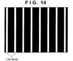
- pattern light for example, pattern light formed from a plurality of line beams shown in Fig. 14 is usable.
- a method of obtaining a peak position from the luminance gradation waveform a method of obtaining the difference value (differential value) of the luminance gradation waveform and setting, as a peak position, a position at which the difference value becomes 0 is adopted in many cases.
- Figs. 15A and 15B are graphs in which the abscissa represents the image coordinate, and the ordinate represents the luminance gradation value.
- Figs. 15A and 15B are enlarged views showing a range near the peak position.
- Figs. 15C and 15D are graphs in which the abscissa represents the image coordinate, and the ordinate represents the difference value of the luminance gradation value.
- the difference value is the difference between the luminance gradation values of a pixel of interest and an adjacent pixel.
- Fig. 15A shows a luminance gradation waveform which does not exceed the saturation level
- Fig. 15C shows the waveform of the difference value of a corresponding image luminance gradation value
- Fig. 15B shows a luminance gradation waveform which exceeds the saturation level
- Fig. 15D shows the waveform of the difference value of a corresponding image luminance gradation value.
- the peak position detection result is obtained uniquely.
- the luminance gradation waveform in Fig. 15B is cut at the saturation level, the range in which the difference value becomes 0 is wide, and the peak position detection result error becomes large.
- the peak position detection accuracy becomes higher as the luminance gradation value becomes larger because of the influence of noise of the image capturing element. That is, even in the method of specifying the position of pattern light by peak position detection, a state is desirable, in which the luminance gradation value is adjusted to a level, one step short of the saturation level.
- the outlines of the above-described bright/dark portion determination processing and the processing in the adjustment unit are applicable. Bright/dark portion determination processing in the modification is different from the first embodiment in the following point.
- the captured images In3 and In4 are necessary to obtain an intersection point position in the space encoding method.
- this modification method using a peak position
- only the captured image of the target object 5 to which pattern light shown in Fig. 14 has been projected is used.
- the position of a pixel in which the differential value of the luminance gradation value becomes 0 in a captured image is specified instead of the intersection point position. Subsequent processing is the same as that in the first embodiment.
- the exposure amount is adjusted based on the luminance gradation value of a pixel used for measurement, the measurement accuracy can be improved. Also, since the mechanism which permits a certain number of pixels to exceed the saturation level is further employed, the exposure amount can be adjusted to improve the measurement accuracy of the entire image even for a highly glossy part.
- exposure amount adjustment based on search is executed.
- the search is accompanied by a plurality of times of image capturing, and thus takes time for exposure amount adjustment, but is effective when there is no knowledge about a target object.
- the search is also effective when the relationship between the adjustment parameter and the luminance of a captured image is unclear.
- FIG. 10 An example of the functional arrangement of an image processing apparatus according to the second embodiment will be described with reference to the block diagram of Fig. 10 .
- the same reference numerals as those in Fig. 1 denote the same functional units, and a description regarding these functional units will not be repeated.
- an appropriate exposure amount calculation unit 47 replaces the bright/dark portion determination unit 42 in the arrangement of Fig. 1 .
- the appropriate exposure amount calculation unit 47 calculates the next appropriate exposure amount from an image captured by an image capturing unit 20 in accordance with an initial exposure amount.
- the second embodiment does not require search, so the time taken for adjustment is shortened, but the initial exposure amount needs to have been adjusted to a proper range to some extent.
- the relationship between the adjustment parameter and the luminance gradation value needs to be grasped. If the exposure time of the image capturing unit is an adjustment parameter, the linearity is high so that when the exposure time is doubled, the luminance gradation value of a captured image is also almost doubled. The exposure time is therefore a desirable adjustment parameter to which the embodiment is applied.
- the adjustment parameter to which the embodiment is applicable is not limited to one having high linearity.
- the relationship between the adjustment parameter and the luminance gradation value is only necessary to find out in advance.
- the relationship between the current value and the luminance gradation value is generally nonlinear.
- the relationship between the LED current value and the luminance gradation value is measured in advance.
- an adjustment unit 41 sets the initial value (parameter) of the exposure amount that has been set in advance or set by the user via an operation unit (not shown). Assume that the initial exposure amount in the embodiment has been adjusted in advance to a proper range to some extent. For example, exposure amount adjustment according to the first embodiment is executed in advance and set as the initial exposure amount.
- a captured image exposure amount control unit 46 controls the exposure amount of the image capturing unit 20.
- the adjustment unit 41 sets the initial value (parameter) of the brightness of pattern light that has been set in advance or set by the user via the operation unit (not shown).
- a pattern light brightness control unit 45 controls the brightness of pattern light projected from a projection unit 30 in accordance with the initial value of the brightness of pattern light.
- step S4122 the projection unit 30 sequentially selects one by one positive and negative patterns, and irradiates a target object 5 with the selected projection pattern.
- the image capturing unit 20 captures the target object 5.
- the 4-bit space encoding method uses a 4-bit pattern.
- the image capturing unit 20 captures the target object 5 every time the selected pattern light is projected.
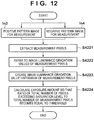
- step S4123 the appropriate exposure amount calculation unit 47 and a pattern position specifying unit 43 perform processing of calculating an appropriate exposure amount (parameter) using an image captured by the image capturing unit 20. Details of the processing in step S4123 will be described later with reference to the flowchart of Fig. 12 .
- step S4124 the captured image exposure amount control unit 46 controls, in accordance with the parameter calculated in step S4123, an exposure amount at the time of image capturing by the image capturing unit 20.
- step S4221 the pattern position specifying unit 43 performs processing of estimating the above-mentioned intersection point position within an adjustment region in a captured image In3 (captured image In4) similarly to the processing in step S4206.
- the appropriate exposure amount calculation unit 47 refers to the luminance gradation values of two points on the positive pattern waveform and two points on the negative pattern waveform, that is, a total of four points (in Fig. 5B , four points having luminance gradation values PR, PL, NR, and NL) which are close to the intersection point position.
- a maximum value out of the referred luminance gradation values at the four points is set as a luminance gradation value at this intersection point position. This processing is performed for each intersection point position.
- step S4223 the appropriate exposure amount calculation unit 47 creates the histogram (distribution) of luminance gradation values obtained in step S4222 for respective intersection point positions.
- step S4224 the appropriate exposure amount calculation unit 47 calculates an exposure amount with which a value obtained by dividing, by the total number of intersection point positions, the number of intersection point positions (number of pixels) each having a luminance gradation value equal to or larger than the saturation level in the histogram becomes equal to a specific threshold within a specific range.
- Fig. 13A shows a histogram before adjustment. Note that the abscissa represents the luminance gradation value, and the ordinate represents the number of pixels. The relationship between the luminance gradation value and the adjustment parameter has been grasped in advance. For this reason, an adjustment parameter at which (total number of pixels equal to or higher than the saturation level)/(total number of measurement pixels) ⁇ threshold is uniquely determined.
- Fig. 13B shows a histogram after adjustment. In accordance with the calculated parameter, the captured image exposure amount control unit 46 controls an exposure amount at the time of image capturing by the image capturing unit 20.
- the parameter for the projection unit 30 may be adjusted, or both the exposure amount and the parameter for the projection unit 30 may be adjusted.
- Each functional unit constituting an image processing unit 40 may be constituted by hardware or software (computer program).
- an apparatus which executes the computer program upon installing the computer program is applicable to the image processing unit 40.
- An example of the hardware arrangement of the apparatus applicable to the image processing unit 40 will be described with reference to the block diagram of Fig. 16 .
- a CPU 1601 controls the operation of the whole apparatus by executing processing using computer programs and data stored in a RAM 1602 and ROM 1603. In addition, the CPU 1601 executes each processing which is performed by the image processing unit 40 in the above description.
- the RAM 1602 has an area for temporarily storing computer programs and data loaded from an external storage device 1606, data externally received via an I/F (interface) 1607, and the like. Further, the RAM 1602 has a work area used when the CPU 1601 executes various processes. That is, the RAM 1602 can appropriately provide various areas.
- the ROM 1603 stores, for example, the setting data and boot program of the apparatus.
- An operation unit 1604 is constituted by a keyboard, mouse, and the like.
- the user of the apparatus can operate the operation unit 1604 to input various instructions to the CPU 1601.
- the above-described adjustment region can be designated by operating the operation unit 1604.
- a display unit 1605 is constituted by a CRT, liquid crystal display, or the like, and can display the result of processing by the CPU 1601 as an image, character, or the like.
- the display unit 1605 can display a screen for designating an adjustment region, including captured images In1 and In2.
- the external storage device 1606 is a large-capacity information storage device typified by a hard disk drive device.
- the external storage device 1606 saves computer programs and data for causing the CPU 1601 to execute an OS (Operating System), or each processing which is performed by each functional unit in the image processing unit 40 shown in Fig. 1 or 10 in the above description.
- the data include even information which has been explained as known information in the above description.
- the computer programs and data saved in the external storage device 1606 are properly loaded to the RAM 1602 under the control of the CPU 1601, and are processed by the CPU 1601.
- the I/F 1607 is used when the apparatus communicates with an external device.
- an image capturing unit 20 or projection unit 30 described above can be connected to the I/F 1607. All the above-mentioned units are connected to a bus 1608.
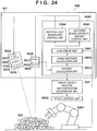
- the target object picking system 508 includes an image processing apparatus (distance measurement apparatus) 501, a target object position and orientation recognition unit 507 which recognizes the position and orientation of a target object 505 by using the result of distance measurement by the image processing apparatus 501, a robot control unit 5062 which controls a robot 5061 by using the recognition result, and the robot 5061.
- the robot 5061 is used to pick the target object 505.
- the image processing apparatus 501 includes a projection unit 5030 which projects pattern light to the target object 505, an image capturing unit 5020 which captures the target object 505 to which the pattern light has been projected, and an image processing unit 5040 which controls the projection unit 5030 and image capturing unit 5020, and performs distance measurement with respect to the target object 505 based on the space encoding method.
- the projection unit 5030 includes a light source 5031, illumination optical system 5032, display element 5033, projection stop 5034, and projection optical system 5035.
- the light source 5031 is, for example, one of various light emitting elements such as a halogen lamp and LED.
- the illumination optical system 5032 is an optical system having a function of guiding light emitted by the light source 5031 to the display element 5033.
- an optical system suited to uniform the luminance such as Koehler illumination or a diffusion plate, is used.
- the display element 5033 is an element having a function of spatially controlling the transmittance or reflectance of light traveling from the illumination optical system 5032 in accordance with a supplied pattern.
- a transmission LCD, reflection LCOS, or DMD is used.
- a plurality of types of patterns held in the projection unit 5030 may be sequentially supplied to the display element 5033.
- a plurality of types of patterns held in an external apparatus may be sequentially acquired and supplied to the display element 5033.
- the projection optical system 5035 is an optical system configured to form light (pattern light) guided from the display element 5033 into an image at a specific position of the target object 505.
- the projection stop 5034 is used to control the f-number of the projection optical system 5035.
- the image capturing unit 5020 includes an image capturing optical system 5023, image capturing stop 5022, and image capturing element 5021.
- the image capturing optical system 5023 is an optical system configured to image a specific position of the target object 505 on the image capturing element 5021.
- the image capturing stop 5022 is used to control the f-number of the image capturing optical system 5023.
- the image capturing element 5021 is, for example, one of various photoelectric conversion elements such as a CMOS sensor and CCD sensor.
- an analog signal photoelectrically converted by the image capturing element 5021 is sampled and quantized by a control unit (not shown) in the image capturing unit 5020, and is converted into a digital image signal. Further, the control unit generates, from the digital image signal, an image (captured image) in which each pixel has a luminance gradation value (density value and pixel value). The control unit appropriately sends the captured image to a memory in the image capturing unit 5020 or to the image processing unit 5040.
- the image capturing unit 5020 captures the target object 505 every time the projection unit 5030 projects different pattern light. More specifically, the image capturing unit 5020 and projection unit 5030 operate synchronously, and the image capturing unit 5020 can capture the image of the target object 505 to which each different pattern light has been projected.
- the image processing unit 5040 includes an adjustment unit 5041, rough distance calculation unit 5042, distance calculation unit 5043, pattern light brightness control unit 5044, and captured image exposure amount control unit 5045.
- the adjustment unit 5041 determines parameters for controlling the bright/dark portion of an image to be captured next time by the image capturing unit 5020.
- the "parameters for controlling the bright/dark portion of an image to be captured next time by the image capturing unit 5020" include a parameter for the image capturing unit 5020, and a parameter for the projection unit 5030. Both or either of the parameters may be determined.
- the distance calculation unit 5043 acquires an image captured by the image capturing unit 5020 every time the projection unit 5030 projects each of a plurality of types of pattern beams. Then, the distance calculation unit 5043 measures (derives) a distance from the image capturing unit 5020 (image capturing optical system 5023) to the target object 505 by the triangulation principle using a space code decoded from the acquired captured image, and a pattern position specified for the acquired captured image.
- the rough distance calculation unit 5042 obtains a rough distance from the distance calculated by the distance calculation unit 5043.
- the pattern light brightness control unit 5044 controls the brightness of pattern light projected from the projection unit 5030 in accordance with the parameter.
- the method of controlling the brightness of pattern light includes, for example, the following three methods.
- the first method is to control the emission luminance of the light source 5031.
- a halogen lamp when the application voltage is increased, the emission luminance increases.
- an LED when a current to be supplied is increased, the emission luminance increases.
- the "parameter for the projection unit 5030" is a parameter for controlling the emission luminance of the light source 5031.
- the second method is to control the display gradation value of the display element 5033.
- the display gradation value In the case of an LCD, when the display gradation value is increased, the transmittance increases, and pattern light becomes bright. In the case of an LCOS, when the display gradation value is increased, the reflectance increases, and pattern light becomes bright. In the case of a DMD, when the display gradation value is increased, the ON count per frame increases, and pattern light becomes bright.
- the "parameter for the projection unit 5030" is a parameter for controlling the display gradation value of the display element 5033.
- the third method is to control the projection stop 5034.
- pattern light becomes bright.
- pattern light becomes dark.
- the depth of field of the projection optical system also changes, so this influence needs to be considered. More specifically, the resolution of pattern light is evaluated at each projection stop based on an index such as the contrast of the image luminance waveform, and it is checked whether serious accuracy degradation will occur when performing distance measurement.
- the "parameter for the projection unit 5030" is a parameter for controlling the projection stop 5034.
- the captured image exposure amount control unit 5045 controls, in accordance with the parameter, an exposure amount at the time of image capturing by the image capturing unit 5020, thereby controlling the luminance gradation value of a captured image.
- the method of controlling the exposure amount of the image capturing unit 5020 includes, for example, the following three methods.
- the first method is to control the exposure time (shutter speed) of the image capturing element 5021.
- the exposure time is prolonged, the luminance gradation value of a captured image increases.
- the exposure time is shortened, the luminance gradation value decreases.
- the "parameter for the image capturing unit 5020" is a parameter for controlling the exposure time (shutter speed) of the image capturing element 5021.
- the second method is to control the image capturing stop 5022.
- the stop When the stop is opened, the luminance gradation value of a captured image increases. Conversely, when the stop is narrowed, the luminance gradation value of a captured image decreases.
- the depth of field of the image capturing optical system also changes, so this influence needs to be considered. More specifically, the resolution of pattern light is evaluated at each image capturing stop based on an index such as the contrast of the image luminance waveform, and it is checked whether serious accuracy degradation will occur when performing distance measurement.
- the "parameter for the image capturing unit 5020" is a parameter for controlling the image capturing stop 5022.
- the third method is to project the same pattern a plurality of times, capture images, and add image luminance values (composite captured images every time the pattern is projected).
- image saturation occurs owing to the dynamic range of the sensor.
- the exposure amount can be increased while preventing image saturation.
- the noise component of the image capturing element is reduced. More specifically, letting ⁇ b be the noise amount of the image capturing element at the time of capturing one image, a noise amount generated when images are captured N times and added is ⁇ b/ ⁇ N.
- the target object 505 is a set of target objects piled at random.
- the target object position and orientation recognition unit 507 recognizes the position and orientation of the target object 505 (in practice, each target object observable from the image capturing unit 5020, out of the target object 505) in a coordinate system (robot coordinate system) handled by the robot 5061 by using the result of distance measurement by the image processing apparatus 501.
- a coordinate system robot coordinate system
- various known recognition methods can be employed. For example, a method of recognizing the position and orientation of a target object by matching processing between a CAD model and 3D point group data based on the distance measurement result may be adopted.
- the target object position and orientation recognition unit 507 may be a unit in the image processing apparatus 501, or an apparatus separate from the image processing apparatus 501. In any case, the target object position and orientation recognition unit 507 may take any form as long as it can recognize the position and orientation of the target object 505 from the result of distance measurement by the image processing apparatus 501, and send the recognized position and orientation to the robot control unit 5062.
- the robot control unit 5062 controls the robot 5061 in accordance with the position and orientation recognized by the target object position and orientation recognition unit 507, and causes the robot 5061 to pick the target object whose position and orientation have been recognized.
- the picked target object is carried to the next step.
- the height of the pile gradually decreases. Along with this, the distance from the image capturing unit 5020 increases.
- the embodiment adopts a method disclosed in Japanese Patent Laid-Open No. 2011-47931 .
- the principle of this method has been described with reference to Figs. 2A to 5B .
- the method is the same as that in the first embodiment, unless otherwise specified.
- the brightness of pattern light or the exposure amount in the image capturing unit 5020 needs to be multiplied by n 2 in order to reduce the error to 1/n.
- the brightness of pattern light or the exposure amount in the image capturing unit 5020 is quadrupled.
- (DL + DR) of the denominator is quadrupled.
- the noise ⁇ as the numerator becomes ⁇ 4 that is, double because it is proportional to the value of the square root of the image luminance gradation value. Since the numerator becomes double and the denominator becomes quadruple, the error becomes 1/2.
- the height of the pile changes as the part is removed, as shown in Figs. 18A to 18C .
- the distance from the image capturing unit 5020 to an image capturing target becomes short, as shown in Fig. 18A .
- the distance from the image capturing unit 5020 to an image capturing target becomes long, as shown in Fig. 18C .
- the luminance value of a part in an image captured by the image capturing unit 5020 decreases in proportion to the square of the distance from the image capturing unit 5020 to the image capturing target.
- a luminance value in an image captured by the image capturing unit 5020 and a distance from the image capturing unit 5020 to an image capturing target will be explained with reference to Figs. 19A to 19C .
- the exposure amount of the image capturing unit 5020 has been set to be optimum at a distance Zm (middle distance) from the image capturing unit 5020 to the image capturing target, as shown in Fig. 19B .
- the waveform of a full light-on pattern and the waveforms of positive and negative patterns partially exceed the saturation level, but a luminance gradation value near an intersection point position used to specify a pattern position does not exceed the saturation level. For this reason, the intersection point position can be specified, and the sub-pixel position estimation error can be reduced because the luminance gradation value near the intersection point becomes large.
- Fig. 19A shows the waveforms of luminance gradation values when the distance from the image capturing unit 5020 to an image capturing target is Zn (short distance) smaller than Zm.
- the waveforms exceed the saturation level at the center.
- Fig. 19A shows the waveforms exceeding the saturation level for convenience. In practice, a waveform exceeding the saturation level is cut at the luminance gradation value of the saturation level and output. In Fig. 19A , the intersection point position is cut at the luminance gradation value of the saturation level, and cannot be specified.
- Fig. 19C shows the waveforms of luminance gradation values when the distance from the image capturing unit 5020 to an image capturing target is Zf (long distance) larger than Zm. In the state of Fig. 19C , none of the waveforms of the luminance gradation values reaches the saturation level, and the distance measurement accuracy is low.
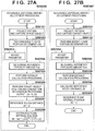
- the processing complying with the flowchart of Fig. 20 includes processing (step S50100) of obtaining an exposure amount serving as a reference (reference exposure amount), and a distance (reference distance) measured using an image captured in the reference exposure amount, and processing (step S50110) of adjusting the exposure amount.
- step S50101 the captured image exposure amount control unit 5045 controls the exposure amount of the image capturing unit 5020 in accordance with the currently set parameter of the exposure amount.
- the pattern light brightness control unit 5044 controls the brightness of pattern light projected from the projection unit 5030 in accordance with the currently set parameter of the brightness of pattern light.
- the projection unit 5030 sequentially selects one by one a plurality of projection patterns described above, and irradiates the target object 505 with the selected projection pattern.
- the image capturing unit 5020 captures the target object 505.
- the types of projection patterns are four: a full light-on pattern, a full light-off pattern, a positive pattern (in Figs. 2A to 2G , the four positive patterns in Figs. 2C to 2F ), and a negative pattern (in Figs. 2A to 2G , the negative pattern in Fig. 2G ).
- the 4-bit space encoding method uses a 4-bit positive pattern as the positive pattern, and a 4-bit negative pattern as the negative pattern.
- the image capturing unit 5020 captures the target object 505 every time the selected pattern light is projected.
- step S50102 the adjustment unit 5041 performs bright/dark portion determination using the image captured by the image capturing unit 5020. Details of the processing in step S50102 are the same as those of the processing complying with the flowchart of Fig. 9 (the adjustment unit 5041 executes the processing complying with the flowchart of Fig. 9 instead of the bright/dark portion determination unit 42), so a description thereof will not be repeated.
- the bright/dark portion determination processing for a captured image that is performed in step S50102 is not limited to the processing complying with the flowchart of Fig. 9 , but may adopt another method.
- step S50103 if the determination result in step S50102 is "bright portion", the adjustment unit 5041 adjusts the parameter of the image capturing unit 5020 in order to adjust the current exposure amount of the image capturing unit 5020 to be smaller (in order to adjust the current exposure time to be shorter). If the determination result in step S50102 is "dark portion", the adjustment unit 5041 adjusts the parameter of the image capturing unit 5020 in order to adjust the current exposure amount of the image capturing unit 5020 to be larger (in order to adjust the current exposure time to be longer).
- the exposure time can be adjusted by, for example, binary search.
- the adjustment unit 5041 sets, in the captured image exposure amount control unit 5045, the adjusted parameter of the image capturing unit 5020.
- the captured image exposure amount control unit 5045 controls the image capturing unit 5020 in accordance with the adjusted parameter from the next time.
- step S50101 image capturing based on the exposure time adjusted in step S50103 is performed. In this way, the processes in steps S50101 to S50103 are repetitively performed a plurality of times.
- step S50104 the adjustment unit 5041 obtains, as a reference exposure amount Exb, an exposure amount (in this case, exposure time) obtained as a result of the repetition.
- the captured image exposure amount control unit 5045 controls the exposure amount of the image capturing unit 5020 in accordance with the reference exposure amount Exb.
- the pattern light brightness control unit 5044 controls the brightness of pattern light projected from the projection unit 5030 in accordance with the currently set parameter of the brightness of pattern light.
- the projection unit 5030 sequentially selects one by one a plurality of projection patterns described above, and irradiates the target object 505 with the selected projection pattern.
- the image capturing unit 5020 captures the target object 505.
- the distance calculation unit 5043 measures distances to respective target objects in the captured image.
- the rough distance calculation unit 5042 obtains a reference distance (reference rough distance) Zb serving as the typical distance of the distances to the respective target objects in the captured image.
- a reference distance reference rough distance
- Processing for obtaining the reference distance Zb from distances to respective target objects in a captured image will be explained with reference to Figs. 21A and 21B.
- Fig. 21A shows an example of the reference distance Zb when the height of the pile is high.
- Fig. 21B shows an example of the reference distance Zb when the height of the pile is middle.
- the average distance of distances to respective target objects in a captured image may be set as the reference distance, or a maximum value, minimum value, median, or the like may be employed as the reference distance.
- step S50111 the captured image exposure amount control unit 5045 controls the exposure amount of the image capturing unit 5020 in accordance with the currently set exposure amount (in step S50111 for the first time, the reference exposure amount Exb, and in step S50111 for the second and subsequent times, an exposure amount Ext adjusted in previous step S50116).
- the pattern light brightness control unit 5044 controls the brightness of pattern light projected from the projection unit 5030 in accordance with the currently set parameter of the brightness of pattern light.
- the projection unit 5030 sequentially selects one by one a plurality of projection patterns described above, and irradiates the target object 505 with the selected projection pattern.
- the image capturing unit 5020 captures the target object 505.
- the distance calculation unit 5043 measures distances to respective target objects in the captured image in step S50112.
- step S50113 the rough distance calculation unit 5042 performs the same processing as that in step S50106 described above, thereby obtaining a typical distance (rough distance) Zt of the distances to the respective target objects in the captured image.
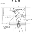
- step S50114 the adjustment unit 5041 obtains a currently set adjustment amount (optical correction amount) Czo of the exposure amount by using the reference distance Zb and distance Zt.
- the optical correction amount Czo is calculated based on an optical characteristic in which the luminance value in an image becomes dark in proportion to the square of the
- step S50115 the adjustment unit 5041 adjusts the reference exposure amount Exb by using the optical correction amount Czo.
- the reference exposure amount Exb is adjusted according to: Czo ⁇ Exb ⁇ Ext
- step S50116 the adjustment unit 5041 sets, in the captured image exposure amount control unit 5045, the exposure amount Ext adjusted in step S50115. The process then returns to step S50111 to repeat the subsequent processes.
- the exposure amount is set to be small in a case in which the height of the pile is high, and to be large in a case in which the height of the pile is low.
- An appropriate exposure amount can be set in accordance with the height of the pile. That is, the luminance value of a captured image can be kept almost constant with respect to a change of the height of the pile.
- distance measurement with respect to the target object 505 is performed based on the space encoding method.
- distance measurement with respect to the target object 505 may be executed by another method.
- a distance measurement method based on various pattern projections such as a light-section method and phase shift method may be adopted.
- the exposure amount is adjusted in consideration of not only the optical correction amount but also a triangulation error.
- a difference from the fourth embodiment will be mainly explained, and the remaining part is the same as that in the fourth embodiment, unless otherwise specified.
- an adjustment unit 5041 obtains an adjustment amount (triangulation correction amount) Czt of the triangulation error by using a reference distance Zb and distance Zt.
- the correction amount is calculated based on a characteristic in which the triangulation error increases in proportion to the square of the distance.
- n the distance measurement error is multiplied by n 2 , as shown in Fig. 23 .
- a sub-pixel position estimation error ⁇ C needs to be 1/n 2 .
- the brightness of pattern light or the exposure amount needs to be multiplied by n 4 , as described above.
- step S50216 the adjustment unit 5041 adjusts the reference exposure amount Exb by using the optical correction amount Czo and triangulation correction amount Czt.
- the reference exposure amount Exb is adjusted according to: Czo ⁇ Czt ⁇ Exb ⁇ Ext
- step S50217 the adjustment unit 5041 sets, in a captured image exposure amount control unit 5045, the exposure amount Ext adjusted in step S50216. The process then returns to step S50111 to repeat the subsequent processes.
- the exposure amount is set to be small in a case in which the height of the pile is high, and to be large in a case in which the height of the pile is low.
- An appropriate exposure amount can be set in accordance with the height of the pile. That is, the luminance value of a captured image can be kept almost constant with respect to a change of the height of the pile. Since even the triangulation error is taken into account, the brightness of a captured image and the measurement error can be kept almost constant with respect to a change of the height of the pile.
- FIG. 24 An example of the functional arrangement of a target object picking system 508 according to the sixth embodiment will be described with reference to the block diagram of Fig. 24 .
- the same reference numerals as those in Fig. 17 denote the same functional units, and a description regarding these functional units will not be repeated.
- the arrangement shown in Fig. 24 is different from the arrangement of Fig. 17 in that a position and orientation recognized by a target object position and orientation recognition unit 507 are supplied not only to a robot control unit 5062 but also to an adjustment unit 5041.
- the sixth embodiment considers not only a change of the light amount upon a change of the distance to a target object, but also a change of the light amount caused by light falloff at edges.
- the adjustment unit 5041 needs to grasp the position of a target object in a captured image (in other words, the angle of view with respect to a range in which the target object exists).
- an output result from the target object position and orientation recognition unit 507 is used.
- processing to be performed by the image processing unit 5040 in order to adjust the exposure amount of an image capturing unit 5020 will be explained with reference to Fig. 26 showing the flowchart of this processing (processing to be executed by the target object position and orientation recognition unit 507 is also partially included).
- the processing complying with the flowchart of Fig. 26 includes processing (step S50300) of obtaining a reference exposure amount Exb, reference distance Zb, and reference plane internal position ⁇ b, and processing (step S50310) of adjusting the exposure amount for each target object.
- step S50300 details of the processing in step S50300 will be explained with reference to the flowcharts of Figs. 27A and 27B .
- Both the flowchart shown in Fig. 27A and the flowchart shown in Fig. 27B are the flowcharts of processes applicable to step S50300.
- Figs. 27A and 27B the same step numbers as those shown in Fig. 20 denote the same processing steps, and a description of these processing steps will not be repeated.
- a captured image exposure amount control unit 5045 controls the exposure amount of the image capturing unit 5020 in accordance with the reference exposure amount Exb.
- a pattern light brightness control unit 5044 controls the brightness of pattern light projected from a projection unit 5030 in accordance with the currently set parameter of the brightness of pattern light.
- the projection unit 5030 sequentially selects one by one a plurality of projection patterns described above, and irradiates a target object 505 with the selected projection pattern.
- the image capturing unit 5020 captures the target object 505.
- a distance calculation unit 5043 measures distances to respective target objects in the captured image.
- the target object position and orientation recognition unit 507 recognizes the positions and orientations of the target objects by using the distances to the respective target objects that have been calculated by the distance calculation unit 5043.
- the adjustment unit 5041 acquires the positions (Xr, Yr, Zr) of the respective target objects recognized by the target object position and orientation recognition unit 507.
- step S50307 the adjustment unit 5041 sets Zr of the target object as the reference distance Zb for the respective target objects in the captured image.
- the adjustment unit 5041 sets, to 0, the reference plane internal position ⁇ b common to respective target objects in a captured image.
- step S50310 details of the processing in step S50310 will be described with reference to Fig. 28 showing the flowchart of this processing.
- Fig. 28 the same step numbers as those shown in Fig. 20 denote the same processing steps, and a description regarding these processing steps will not be repeated.
- the target object position and orientation recognition unit 507 recognizes the position and orientation of each target object by using a distance calculated by the distance calculation unit 5043 for the target object in an image captured in step S50111. At this time, the target object position and orientation recognition unit 507 sends, to the robot control unit 5062, the position of a target object (candidate 1) that has been output to the adjustment unit 5041 previously. Also, the target object position and orientation recognition unit 507 outputs, to the adjustment unit 5041, the position of one target object (candidate 2) that has not been output yet. In addition to the position, the orientation may be output to the robot control unit 5062.
- the target object position and orientation recognition unit 507 recognizes the position and orientation of target object 1, the position and orientation of target object 2, the position and orientation of target object 3, and the position and orientation of target object 4. Also, assume that Zr of target object 3 is smallest among Zr of target objects 1 to 4.
- the target object position and orientation recognition unit 507 outputs the position (may also output the orientation) of target object 3 serving as candidate 1 to the robot control unit 5062, and outputs the position of target object 1 serving as candidate 2 to the adjustment unit 5041.
- the target object position and orientation recognition unit 507 outputs the position (may also output the orientation) of target object 1 serving as candidate 1 to the robot control unit 5062, and outputs the position of target object 2 serving as candidate 2 to the adjustment unit 5041.
- the target object position and orientation recognition unit 507 outputs the position (may also output the orientation) of target object 2 serving as candidate 1 to the robot control unit 5062, and outputs the position of target object 3 serving as candidate 2 to the adjustment unit 5041.
- the target object position and orientation recognition unit 507 outputs the position (may also output the orientation) of target object 3 serving as candidate 1 to the robot control unit 5062, and outputs the position of target object 4 serving as candidate 2 to the adjustment unit 5041.
- the target object position and orientation recognition unit 507 outputs the position of target object 4 to the robot control unit 5062.
- the position of the second candidate is output to the adjustment unit 5041.
- a target object which was previously the second candidate is set as the first candidate this time. Then, the position of the first candidate time this is output (the orientation may also be output) to the robot control unit 5062.
- step S50314 upon receiving the position (Xr2, Yr2, Zr2) of the second candidate, the adjustment unit 5041 sets Zr2 in the rough distance Zt.
- step S50315 the adjustment unit 5041 obtains an optical correction amount Czo by solving the above-described equation (3) using the reference distance Zb and rough distance Zt.
- step S50316 the adjustment unit 5041 obtains a triangulation correction amount Czt by solving the above-described equation (5) using the reference distance Zb and rough distance Zt.
- step S50317 the adjustment unit 5041 obtains an angle ⁇ r of view with respect to the second candidate by solving the above-described equation (9) using the position (Xr2, Yr2, Zr2) of the second candidate.
- step S50319 the adjustment unit 5041 adjusts the reference exposure amount Exb by solving expression (11), and obtains the exposure amount Ext for the second candidate as the result of adjustment: Czo ⁇ Czt ⁇ C ⁇ ⁇ Exb ⁇ Ext
- the adjustment unit 5041 every time the adjustment unit 5041 receives the position of the second candidate, it calculates Ext for the second candidate. According to the embodiment, even if the position of a target object to be recognized in the frame changes in addition to the height of the pile, an appropriate exposure amount can be set.
- the exposure amount is set to be small near the center of the frame at which the angle of view is small, and to be large at the edge of the frame at which the angle of view is large.
- the embodiment has described an example in which the position of a target object in a captured image is grasped based on the position and orientation recognition result of the target object.
- the position and orientation recognition result of a target object need not always be used.
- an area in which a target object is captured in a captured image is divided into a plurality of areas, and a rough distance is calculated for each divided area.
- the center position of an area having a smallest rough distance among the divided areas is regarded as a position at which the target object exists.
- step S50318 described above light falloff at edges depending on the position (angle of view) in a captured image is formulated on the assumption that it is based on the cosine fourth-power law.
- the present invention is not limited to this.
- a proper equation can be used in accordance with this characteristic.
- Each functional unit constituting an image processing unit 5040 may be constituted by hardware or software (computer program).
- an apparatus which executes the computer program upon installing the computer program is applicable to the image processing unit 5040.
- the hardware arrangement of the apparatus applicable to the image processing unit 5040 for example, the arrangement shown in the block diagram of Fig. 16 is applicable.
- Embodiment(s) of the present invention can also be realized by a computer of a system or apparatus that reads out and executes computer executable instructions (e.g., one or more programs) recorded on a storage medium (which may also be referred to more fully as a 'non-transitory computer-readable storage medium') to perform the functions of one or more of the above-described embodiment(s) and/or that includes one or more circuits (e.g., application specific integrated circuit (ASIC)) for performing the functions of one or more of the above-described embodiment(s), and by a method performed by the computer of the system or apparatus by, for example, reading out and executing the computer executable instructions from the storage medium to perform the functions of one or more of the above-described embodiment(s) and/or controlling the one or more circuits to perform the functions of one or more of the above-described embodiment(s).
- computer executable instructions e.g., one or more programs
- a storage medium which may also be referred to more fully as
- the computer may comprise one or more processors (e.g., central processing unit (CPU), micro processing unit (MPU)) and may include a network of separate computers or separate processors to read out and execute the computer executable instructions.
- the computer executable instructions may be provided to the computer, for example, from a network or the storage medium.
- the storage medium may include, for example, one or more of a hard disk, a random-access memory (RAM), a read only memory (ROM), a storage of distributed computing systems, an optical disk (such as a compact disc (CD), digital versatile disc (DVD), or Blu-ray Disc (BD)TM), a flash memory device, a memory card, and the like.
Landscapes
- Physics & Mathematics (AREA)
- General Physics & Mathematics (AREA)
- Engineering & Computer Science (AREA)
- Computer Vision & Pattern Recognition (AREA)
- Multimedia (AREA)
- Signal Processing (AREA)
- Length Measuring Devices By Optical Means (AREA)
- Measurement Of Optical Distance (AREA)
Claims (24)
- Bildverarbeitungsvorrichtung (40), umfassend:eine Erfassungseinrichtung (43), die konfiguriert ist zum Erfassen eines aufgenommenen Bildes, das mittels Aufnehmen eines Zielobjekts (5), auf welches ein Muster projiziert wurde, durch eine Bildaufnahmeeinrichtung (20) erhalten wurde;eine Anpassungseinrichtung (41, 42), die konfiguriert ist, basierend auf dem Muster im erfassten aufgenommenen Bild einen ersten Parameter zum Steuern der Helligkeit des von einer zum Projizieren des Musters konfigurierten Projektionseinrichtung projizierten Musters und/oder einen zweiten Parameter zum Steuern einer Belichtungsmenge der Bildaufnahmeeinrichtung anzupassen; undeine Einrichtung (43) zum Spezifizieren einer Position des Musters, die konfiguriert ist, einen Schnittpunkt zu erhalten zwischen einer Luminanzwert-Wellenform, die gebildet ist aus Luminanzwerten jeweiliger Pixel, die ein erstes aufgenommenes Bild des Zielobjekts bilden, auf welches ein erstes Muster projiziert worden ist, und einer Luminanzwert-Wellenform, die gebildet ist aus Luminanzwerten jeweiliger Pixel, die ein zweites aufgenommenes Bild des Zielobjekts bilden, auf welches ein durch Umkehren heller und dunkler Abschnitte im ersten Muster erhaltenes zweites Muster projiziert worden ist;dadurch gekennzeichnet, dassdie Anpassungseinrichtung konfiguriert ist, den ersten Parameter zum Steuern der Helligkeit des von der Projektionseinrichtung projizierten Musters, zum Verdunkeln des Musters, und/oder den zweiten Parameter zum Steuern der Belichtungsmenge der Bildaufnahmeeinrichtung, zum Verringern der Belichtungsmenge, anzupassen, wenn ein Verhältnis zwischen der Zahl an Schnittpunkten und einer Zahl an Pixeln eines vorbestimmten Gebiets nicht über einem Schwellenwert liegt.
- Vorrichtung nach Anspruch 1, dadurch gekennzeichnet, dass die Anpassungseinrichtung konfiguriert ist, den ersten Parameter zum Steuern der Helligkeit des von der Projektionseinrichtung projizierten Musters, zum Verdunkeln des Musters, oder den zweiten Parameter zum Steuern der Belichtungsmenge der Bildaufnahmeeinrichtung, zum Verringern der Belichtungsmenge, anzupassen, wenn das Verhältnis nicht über dem Schwellenwert liegt.
- Vorrichtung nach Anspruch 1, dadurch gekennzeichnet, dass die Anpassungseinrichtung konfiguriert ist, den ersten Parameter zum Steuern der Helligkeit des von der Projektionseinrichtung projizierten Musters, zum Verdunkeln des Musters, und den zweiten Parameter zum Steuern der Belichtungsmenge der Bildaufnahmeeinrichtung, zum Verringern der Belichtungsmenge, anzupassen, wenn das Verhältnis nicht über dem Schwellenwert liegt.
- Vorrichtung nach Anspruch 2, dadurch gekennzeichnet, dassdie Anpassungseinrichtung konfiguriert ist, als ein zweites Verhältnis ein Verhältnis zwischen der Anzahl an Schnittpunkten und der Anzahl an durch Bezugnahme auf Pixel mit gesättigten Pixelwerten erhaltenen Schnittpunkten zu erhalten, wenn das Verhältnis über dem Schwellenwert liegt,die Anpassungseinrichtung konfiguriert ist, den ersten Parameter zum Steuern der Helligkeit des von der Projektionseinrichtung projizierten Musters, zum Verdunkeln des Musters, oder den zweiten Parameter zum Steuern der Belichtungsmenge der Bildaufnahmeeinrichtung, zum Verringern der Belichtungsmenge, anzupassen, wenn das zweite Verhältnis über einem Schwellenwert liegt, unddie Anpassungseinrichtung konfiguriert ist, den ersten Parameter zum Steuern der Helligkeit des von der Projektionseinrichtung projizierten Musters, zum Aufhellen des Musters, oder den zweiten Parameter zum Steuern der Belichtungsmenge der Bildaufnahmeeinrichtung, zum Erhöhen der Belichtungsmenge, anzupassen, wenn das zweite Verhältnis nicht über dem Schwellenwert liegt.
- Vorrichtung nach Anspruch 3, dadurch gekennzeichnet, dassdie Anpassungseinrichtung konfiguriert ist, als ein zweites Verhältnis ein Verhältnis zwischen der Anzahl an Schnittpunkten und der Anzahl an durch Bezugnahme auf Pixel mit gesättigten Pixelwerten erhaltenen Schnittpunkten zu erhalten, wenn das Verhältnis über dem Schwellenwert liegt,die Anpassungseinrichtung konfiguriert ist, den ersten Parameter zum Steuern der Helligkeit des von der Projektionseinrichtung projizierten Musters, zum Verdunkeln des Musters, und den zweiten Parameter zum Steuern der Belichtungsmenge der Bildaufnahmeeinrichtung, zum Verringern der Belichtungsmenge, anzupassen, wenn das zweite Verhältnis über einem Schwellenwert liegt, unddie Anpassungseinrichtung konfiguriert ist, den ersten Parameter zum Steuern der Helligkeit des von der Projektionseinrichtung projizierten Musters zum Aufhellen des Musters anzupassen und den zweiten Parameter zum Steuern der Belichtungsmenge der Bildaufnahmeeinrichtung zum Erhöhen der Belichtungsmenge anzupassen, wenn das zweite Verhältnis nicht über dem Schwellenwert liegt.
- Vorrichtung nach Anspruch 1, dadurch gekennzeichnet, dass die Vorrichtung ferner umfasst:eine Einrichtung, die konfiguriert ist, einen maximalen Pixelwert aus Pixelwerten jeweiliger Pixel zu spezifizieren, auf die zum Detektieren einer Position des Musters aus dem aufgenommenen Bild Bezug genommen wird, und eine Verteilung des maximalen Pixelwerts zu erfassen; undwobei die Anpassungseinrichtung konfiguriert ist, ferner durch Nutzen der Verteilung den ersten Parameter zum Steuern der Helligkeit des von einer zum Projizieren des Musters konfigurierten Projektionseinrichtung projizierten Musters oder den zweiten Parameter zum Steuern einer Belichtungsmenge der Bildaufnahmeeinrichtung anzupassen.
- Vorrichtung nach Anspruch 6, dadurch gekennzeichnet, dass die Anpassungseinrichtung konfiguriert ist, den ersten Parameter zum Steuern der Helligkeit des von der Projektionseinrichtung projizierten Musters oder den zweiten Parameter zum Steuern der Belichtungsmenge der Bildaufnahmeeinrichtung anzupassen, damit sich ein Wert, der erhalten wurde durch Teilen der Anzahl an Pixeln mit einem jeweils nicht unter einem Sättigungsniveau liegenden Pixelwert durch die Anzahl an Positionen, einem Schwellenwert angleicht.
- Vorrichtung nach den Ansprüchen 1 bis 7, dadurch gekennzeichnet, dass die Vorrichtung ferner eine Einrichtung umfasst, die zum Durchführen von Entfernungsmessung bezüglich des Zielobjekts unter Verwendung eines von der Bildaufnahmeeinrichtung aufgenommenen Bilds konfiguriert ist.
- Vorrichtung nach den Ansprüchen 1 bis 8, dadurch gekennzeichnet, dass das aufgenommene Bild ein Bild in einem Gebiet ist, in dem das Zielobjekt in einem von der Bildaufnahmeeinrichtung aufgenommenen Bild aufgenommen wird.
- Vorrichtung nach Anspruch 1, dadurch gekennzeichnet, dass die Vorrichtung ferner umfasst:eine Ableitungseinrichtung, die konfiguriert ist, unter Verwendung des aufgenommenen Bilds einen Abstand zwischen der Bildaufnahmeeinrichtung und dem Zielobjekt abzuleiten,wobei die Anpassungseinrichtung konfiguriert ist, gemäß dem abgeleiteten Abstand den ersten Parameter zum Steuern der Helligkeit des von der Projektionseinrichtung projizierten Musters und/oder den zweiten Parameter zum Steuern der Belichtungsmenge der Bildaufnahmeeinrichtung weiter anzupassen.
- Vorrichtung nach Anspruch 10, dadurch gekennzeichnet, dass die Vorrichtung ferner umfasst:eine Einrichtung, die konfiguriert ist, nach der Anpassung durch die Anpassungseinrichtung gemäß einer Luminanz des aufgenommenen Bilds ein aufgenommenes Bild zu erfassen, das erhalten wurde durch Aufnehmen eines Zielobjekts, auf das durch die Projektionseinrichtung, in der der erste Parameter eingestellt worden ist, ein Muster projiziert worden ist, durch die Bildaufnahmeeinrichtung, in der der zweite Parameter eingestellt worden ist, und als Referenzabstand einen Abstand zwischen der Bildaufnahmeeinrichtung und dem Zielobjekt unter Verwendung des erfassten aufgenommenen Bilds zu berechnen,wobei die Anpassungseinrichtung konfiguriert ist, den ersten Parameter und/oder den zweiten Parameter durch Verwenden eines Verhältnisses zwischen dem durch die Ableitungseinrichtung abgeleiteten Abstand und dem Referenzabstand anzupassen.
- Vorrichtung nach Anspruch 11, dadurch gekennzeichnet, dass die Anpassungseinrichtung konfiguriert ist, ein Anpassungsziel aus dem ersten Parameter und dem zweiten Parameter durch Multiplizieren des Anpassungsziels mit einem durch Quadrieren des Verhältnisses erhaltenen Wert anzupassen.
- Vorrichtung nach Anspruch 11, dadurch gekennzeichnet, dass die Anpassungseinrichtung konfiguriert ist, zum Steuern einer Belichtungszeit den zweiten Parameter durch Multiplizieren eines im zweiten Parameter enthaltenen Parameters mit einem durch Quadrieren des Verhältnisses erhaltenen Wert anzupassen und zum Steuern einer Bildaufnahmezahl den zweiten Parameter durch Multiplizieren eines im zweiten Parameter enthaltenen Parameters mit einem als vierte Potenz des Verhältnisses erhaltenen Wert anzupassen.
- Vorrichtung nach den Ansprüchen 11 bis 13, dadurch gekennzeichnet, dass die Anpassungseinrichtung konfiguriert ist, gemäß dem Abstand und einer Position des Zielobjekts den ersten Parameter und/oder den zweiten Parameter anzupassen.
- Vorrichtung nach Anspruch 1, dadurch gekennzeichnet, dass die Anpassungseinrichtung konfiguriert ist, den ersten Parameter, zur Verdunkelung des Musters, oder den zweiten Parameter, zum Verringern des Belichtungswerts, anzupassen, wenn ein Verhältnis zwischen der Anzahl an Schnittpunkten und der Anzahl an Pixeln in einem als ein Nichtschattengebiet spezifizierten Gebiet im ersten aufgenommenen Bild oder dem zweiten aufgenommenen Bild nicht über einem Schwellenwert liegt.
- Vorrichtung nach Anspruch 1, dadurch gekennzeichnet, dass die Anpassungseinrichtung konfiguriert ist, den ersten Parameter, zur Verdunkelung des Musters, und den zweiten Parameter, zum Verringern des Belichtungswerts, anzupassen, wenn ein Verhältnis zwischen der Anzahl an Schnittpunkten und der Anzahl an Pixeln in einem als ein Nichtschattengebiet spezifizierten Gebiet im ersten aufgenommenen Bild oder dem zweiten aufgenommenen Bild nicht über einem Schwellenwert liegt.
- Vorrichtung nach Anspruch 1, dadurch gekennzeichnet, dassdie Anpassungseinrichtung konfiguriert ist, als ein zweites Verhältnis ein Verhältnis zwischen der Anzahl an durch Bezugnahme auf Pixel mit gesättigten Pixelwerten erhaltenen Schnittpunkten und der Anzahl an Schnittpunkten zu erhalten, wenn ein Verhältnis zwischen der Anzahl an Schnittpunkten und der Anzahl an Pixeln in einem als ein Nichtschattengebiet spezifizierten Gebiet im ersten aufgenommenen Bild oder dem zweiten aufgenommenen Bild über einem Schwellenwert liegt, unddie Anpassungseinrichtung konfiguriert ist, den ersten Parameter zur Verdunkelung des Musters oder den zweiten Parameter zum Verringern der Belichtungsmenge anzupassen, wenn das zweite Verhältnis über einem Schwellenwert liegt.
- Vorrichtung nach Anspruch 1, dadurch gekennzeichnet, dassdie Anpassungseinrichtung konfiguriert ist, als ein zweites Verhältnis ein Verhältnis zwischen der Anzahl an durch Bezugnahme auf Pixel mit gesättigten Pixelwerten erhaltenen Schnittpunkten und der Anzahl an Schnittpunkten zu erhalten, wenn ein Verhältnis zwischen der Anzahl an Schnittpunkten und der Anzahl an Pixeln in einem als ein Nichtschattengebiet spezifizierten Gebiet im ersten aufgenommenen Bild oder dem zweiten aufgenommenen Bild über einem Schwellenwert liegt, unddie Anpassungseinrichtung konfiguriert ist, den ersten Parameter zur Verdunkelung des Musters und den zweiten Parameter zum Verringern der Belichtungsmenge anzupassen, wenn das zweite Verhältnis über einem Schwellenwert liegt.
- Vorrichtung nach Anspruch 1, dadurch gekennzeichnet, dassdie Anpassungseinrichtung konfiguriert ist, als ein zweites Verhältnis ein Verhältnis zwischen der Anzahl an durch Bezugnahme auf Pixel mit gesättigten Pixelwerten erhaltenen Schnittpunkten und der Anzahl an Schnittpunkten zu erhalten, wenn ein Verhältnis zwischen der Anzahl an Schnittpunkten und der Anzahl an Pixeln in einem als Nichtschattengebiet spezifizierten Gebiet im ersten aufgenommenen Bild oder dem zweiten aufgenommenen Bild über einem Schwellenwert liegt, unddie Anpassungseinrichtung konfiguriert ist, den ersten Parameter zur Aufhellung des Musters oder den zweiten Parameter zum Erhöhen der Belichtungsmenge anzupassen, wenn das zweite Verhältnis nicht über einem Schwellenwert liegt.
- Vorrichtung nach Anspruch 1, dadurch gekennzeichnet, dassdie Anpassungseinrichtung konfiguriert ist, als ein zweites Verhältnis ein Verhältnis zwischen der Anzahl an durch Bezugnahme auf Pixel mit gesättigten Pixelwerten erhaltenen Schnittpunkten und der Anzahl an Schnittpunkten zu erhalten, wenn ein Verhältnis zwischen der Anzahl an Schnittpunkten und der Anzahl an Pixeln in einem als Nichtschattengebiet spezifizierten Gebiet im ersten aufgenommenen Bild oder dem zweiten aufgenommenen Bild über einem Schwellenwert liegt, unddie Anpassungseinrichtung konfiguriert ist, den ersten Parameter zur Aufhellung des Musters und den zweiten Parameter zum Erhöhen der Belichtungsmenge anzupassen, wenn das zweite Verhältnis nicht über einem Schwellenwert liegt.
- Vorrichtung nach einem der Ansprüche 1 bis 20, dadurch gekennzeichnet, dass der erste Parameter zum Steuern mindestens eines der Folgenden dient: Emissionsluminanz einer Lichtquelle der Projektionseinrichtung, Anzeigegradationswert des Anzeigeelements der Projektionseinrichtung, und Projektionsblende der Bildaufnahmeeinrichtung.
- Vorrichtung nach einem der Ansprüche 1 bis 21, dadurch gekennzeichnet, dass der zweite Parameter zum Steuern der Belichtungszeit der Bildaufnahmeeinrichtung und/oder der Bildaufnahmeblende der Bildaufnahmeeinrichtung dient.
- Bildverarbeitungsverfahren um durch eine Bildverarbeitungsvorrichtung durchgeführt zu werden, umfassend:Erfassen eines aufgenommenen Bildes, das durch Aufnehmen eines Zielobjekts, auf welches ein Muster projiziert worden ist, durch eine Bildaufnahmeeinrichtung erhalten wurde;Anpassen eines ersten Parameters zum Steuern der Helligkeit des von einer zum Projizieren des Musters konfigurierten Projektionseinrichtung projizierten Musters und/oder eines zweiten Parameters zum Steuern einer Belichtungsmenge der Bildaufnahmeeinrichtung, basierend auf dem Muster im erfassten aufgenommenen Bild; undErhalten eines Schnittpunkts zwischen einer Luminanzwert-Wellenform gebildet aus Luminanzwerten jeweiliger Pixel, die ein erstes aufgenommenes Bild des Zielobjekts bilden, auf welches ein erstes Muster projiziert worden ist, und einer Luminanzwert-Wellenform gebildet aus Luminanzwerten jeweiliger Pixel, die ein zweites aufgenommenes Bild des Zielobjekts bilden, auf welches ein durch Umkehren heller und dunkler Abschnitte im ersten Muster erhaltenes zweites Muster projiziert worden ist;gekennzeichnet durchAnpassen des ersten Parameters zum Steuern der Helligkeit des von der Projektionseinrichtung projizierten Musters zum Verdunkeln des Musters und/oder des zweiten Parameters zum Steuern der Belichtungsmenge der Bildaufnahmeeinrichtung zum Verringern der Belichtungsmenge, wenn ein Verhältnis zwischen der Anzahl an Schnittpunkten und der Anzahl an Pixeln eines vorbestimmten Gebiets nicht über einem Schwellenwert liegt.
- Computerprogramm, das bei Ausführen auf einem Computer den Computer veranlasst, als die Bildverarbeitungsvorrichtung nach einem der Ansprüche 1 bis 22 zu arbeiten.
Applications Claiming Priority (2)
| Application Number | Priority Date | Filing Date | Title |
|---|---|---|---|
| JP2013225819A JP6267486B2 (ja) | 2013-10-30 | 2013-10-30 | 画像処理装置、画像処理方法 |
| JP2013225821A JP6346427B2 (ja) | 2013-10-30 | 2013-10-30 | 画像処理装置、画像処理方法 |
Publications (2)
| Publication Number | Publication Date |
|---|---|
| EP2869023A1 EP2869023A1 (de) | 2015-05-06 |
| EP2869023B1 true EP2869023B1 (de) | 2018-06-13 |
Family
ID=51794711
Family Applications (1)
| Application Number | Title | Priority Date | Filing Date |
|---|---|---|---|
| EP14003573.4A Active EP2869023B1 (de) | 2013-10-30 | 2014-10-20 | Bildverarbeitungsvorrichtung, Bildverarbeitungsverfahren und entsprechendes Computerprogramm |
Country Status (3)
| Country | Link |
|---|---|
| US (2) | US9819872B2 (de) |
| EP (1) | EP2869023B1 (de) |
| CN (1) | CN104601899B (de) |
Cited By (1)
| Publication number | Priority date | Publication date | Assignee | Title |
|---|---|---|---|---|
| US10853971B2 (en) | 2017-02-01 | 2020-12-01 | Carl Zeiss Industrielle Messtechnik Gmbh | Method for determining the exposure time for a 3D recording |
Families Citing this family (33)
| Publication number | Priority date | Publication date | Assignee | Title |
|---|---|---|---|---|
| JP6338421B2 (ja) | 2014-03-31 | 2018-06-06 | キヤノン株式会社 | 情報処理装置、情報処理装置の制御方法、把持システムおよびプログラム |
| JP2015206950A (ja) * | 2014-04-22 | 2015-11-19 | ソニー株式会社 | 情報処理装置、情報処理方法、プログラム、調整装置、及び画像表示システム |
| CN104185001B (zh) * | 2014-09-09 | 2018-08-31 | 联想(北京)有限公司 | 一种控制方法和装置 |
| WO2016129160A1 (ja) * | 2015-02-12 | 2016-08-18 | ソニー株式会社 | 画像処理装置、画像処理方法、プログラムおよび画像処理システム |
| JP2017003469A (ja) * | 2015-06-11 | 2017-01-05 | キヤノン株式会社 | 三次元計測装置、三次元計測装置の制御方法及びプログラム |
| JP6566737B2 (ja) | 2015-06-18 | 2019-08-28 | キヤノン株式会社 | 情報処理装置、情報処理方法、プログラム |
| CN105072429B (zh) * | 2015-08-17 | 2018-06-01 | 联想(北京)有限公司 | 一种投影方法及装置 |
| JP6027204B1 (ja) * | 2015-10-05 | 2016-11-16 | Ckd株式会社 | 三次元計測装置 |
| JP6566832B2 (ja) * | 2015-10-16 | 2019-08-28 | Ckd株式会社 | 三次元計測装置 |
| KR101737518B1 (ko) * | 2015-10-27 | 2017-05-18 | 성균관대학교산학협력단 | 구조광 기반 3차원 카메라의 최적 노출 시간 및 횟수 결정 방법과 시스템 |
| JP6024841B1 (ja) * | 2016-01-27 | 2016-11-16 | 株式会社リコー | 照明装置、パターン照射装置およびシステム |
| CN108603745B (zh) * | 2016-02-04 | 2020-04-28 | 富士胶片株式会社 | 信息处理装置、信息处理方法及程序 |
| JP6758903B2 (ja) * | 2016-05-06 | 2020-09-23 | キヤノン株式会社 | 情報処理装置、情報処理方法、プログラム、システム、および物品製造方法 |
| KR101842141B1 (ko) * | 2016-05-13 | 2018-03-26 | (주)칼리온 | 3차원 스캐닝 장치 및 방법 |
| US9947099B2 (en) | 2016-07-27 | 2018-04-17 | Microsoft Technology Licensing, Llc | Reflectivity map estimate from dot based structured light systems |
| JP6534780B2 (ja) * | 2016-10-04 | 2019-06-26 | 富士フイルム株式会社 | 撮像装置、撮像方法、およびプログラム |
| US10277842B1 (en) | 2016-11-29 | 2019-04-30 | X Development Llc | Dynamic range for depth sensing |
| CN108240800B (zh) * | 2016-12-23 | 2020-03-10 | 致茂电子(苏州)有限公司 | 表面形貌的量测方法 |
| JP6917781B2 (ja) * | 2017-05-31 | 2021-08-11 | 株式会社キーエンス | 画像検査装置 |
| JP6997541B2 (ja) * | 2017-05-31 | 2022-01-17 | 株式会社キーエンス | 画像検査装置、画像検査プログラム及びコンピュータで読み取り可能な記録媒体並びに記録した機器 |
| JP6970376B2 (ja) | 2017-12-01 | 2021-11-24 | オムロン株式会社 | 画像処理システム、及び画像処理方法 |
| US20190202372A1 (en) * | 2018-01-03 | 2019-07-04 | Getac Technology Corporation | Vehicular image pickup device and image capturing method |
| DE102018102159A1 (de) * | 2018-01-31 | 2019-08-01 | Carl Zeiss Industrielle Messtechnik Gmbh | Verfahren zum Bestimmen der Belichtungszeit für eine 3D-Aufnahme |
| US11061234B1 (en) * | 2018-02-01 | 2021-07-13 | Facebook Technologies, Llc | Depth camera assembly based on near infra-red illuminator |
| CN112119628B (zh) | 2018-03-20 | 2022-06-03 | 魔眼公司 | 调整相机曝光以用于三维深度感测和二维成像 |
| CN108955575B (zh) * | 2018-08-22 | 2019-09-17 | 江南大学 | 一种基于单幅干涉条纹高精度地恢复波面的方法 |
| CN109510948B (zh) * | 2018-09-30 | 2020-11-17 | 先临三维科技股份有限公司 | 曝光调整方法、装置、计算机设备和存储介质 |
| JP7398884B2 (ja) * | 2019-05-14 | 2023-12-15 | キヤノン株式会社 | 撮像装置、発光制御装置、撮像方法、発光制御方法、及びプログラム |
| US11340456B1 (en) | 2019-05-22 | 2022-05-24 | Facebook Technologies, Llc | Addressable crossed line projector for depth camera assembly |
| CN112082508B (zh) * | 2020-08-10 | 2022-07-12 | 中国科学院深圳先进技术研究院 | 反光物体的三维测量方法、装置及终端设备 |
| CN113014826B (zh) * | 2021-02-18 | 2023-05-05 | 科络克电子科技(上海)有限公司 | 一种图像感光强度参数调整方法、装置、设备及介质 |
| EP4138384A3 (de) * | 2021-08-16 | 2023-04-19 | Canon Kabushiki Kaisha | Bildgebungsvorrichtung, bildgebungssteuerungsverfahren und speichermedium |
| CN114683504B (zh) * | 2022-03-07 | 2023-10-31 | 佳睦拉索(上海)有限公司 | 一种注塑产品成型控制方法及控制设备 |
Family Cites Families (23)
| Publication number | Priority date | Publication date | Assignee | Title |
|---|---|---|---|---|
| EP0726543B1 (de) | 1995-02-07 | 2003-09-10 | Canon Kabushiki Kaisha | Verfahren und Einrichtung zur Bildverarbeitung |
| EP0732672B1 (de) | 1995-03-17 | 2002-08-14 | Canon Kabushiki Kaisha | Verfahren und Gerät zur dreidimensionalen Bildverarbeitung |
| JPH10255069A (ja) | 1997-03-10 | 1998-09-25 | Canon Inc | 画像処理システム |
| JPH10255081A (ja) | 1997-03-10 | 1998-09-25 | Canon Inc | 画像処理方法及び画像処理装置 |
| JP2000241131A (ja) | 1998-12-22 | 2000-09-08 | Matsushita Electric Ind Co Ltd | レンジファインダ装置および撮像装置 |
| US6876392B1 (en) | 1998-12-22 | 2005-04-05 | Matsushita Electric Industrial Co., Ltd. | Rangefinder for obtaining information from a three-dimensional object |
| JP2000292133A (ja) | 1999-04-02 | 2000-10-20 | Nippon Steel Corp | パターン投影装置 |
| JP4532856B2 (ja) | 2003-07-08 | 2010-08-25 | キヤノン株式会社 | 位置姿勢計測方法及び装置 |
| US20080267450A1 (en) * | 2005-06-14 | 2008-10-30 | Maki Sugimoto | Position Tracking Device, Position Tracking Method, Position Tracking Program and Mixed Reality Providing System |
| JP2008032608A (ja) * | 2006-07-31 | 2008-02-14 | Aisin Seiki Co Ltd | 三次元形状測定装置及び三次元形状測定方法 |
| DE102006048234A1 (de) * | 2006-10-11 | 2008-04-17 | Steinbichler Optotechnik Gmbh | Verfahren und Vorrichtung zur Bestimmung der 3D-Koordinaten eines Objekts |
| JP5256745B2 (ja) * | 2008-01-17 | 2013-08-07 | 株式会社ニコン | 三次元形状計測装置 |
| JP2009250844A (ja) | 2008-04-08 | 2009-10-29 | Toyota Motor Corp | 三次元形状計測方法および三次元形状計測装置 |
| US8717416B2 (en) * | 2008-09-30 | 2014-05-06 | Texas Instruments Incorporated | 3D camera using flash with structured light |
| WO2010073582A1 (ja) * | 2008-12-22 | 2010-07-01 | パナソニック株式会社 | 画像拡大装置、方法、集積回路及びプログラム |
| JP5669212B2 (ja) * | 2009-06-08 | 2015-02-12 | 国立大学法人 名古屋工業大学 | 3次元情報提示装置 |
| WO2011013373A1 (en) | 2009-07-29 | 2011-02-03 | Canon Kabushiki Kaisha | Measuring apparatus, measuring method, and program |
| JP2012068176A (ja) | 2010-09-27 | 2012-04-05 | Panasonic Corp | 三次元形状計測装置 |
| JP2012141252A (ja) * | 2011-01-06 | 2012-07-26 | Nikon Corp | 三次元形状測定装置 |
| JP5918984B2 (ja) | 2011-12-06 | 2016-05-18 | キヤノン株式会社 | 情報処理装置、情報処理装置の制御方法、およびプログラム |
| JP5848662B2 (ja) | 2012-04-04 | 2016-01-27 | キヤノン株式会社 | 画像処理装置およびその制御方法 |
| JP6029394B2 (ja) * | 2012-09-11 | 2016-11-24 | 株式会社キーエンス | 形状測定装置 |
| JP6061616B2 (ja) | 2012-10-29 | 2017-01-18 | キヤノン株式会社 | 測定装置及びその制御方法、プログラム |
-
2014
- 2014-10-20 EP EP14003573.4A patent/EP2869023B1/de active Active
- 2014-10-21 US US14/519,270 patent/US9819872B2/en active Active
- 2014-10-30 CN CN201410601537.3A patent/CN104601899B/zh active Active
-
2017
- 2017-09-26 US US15/715,297 patent/US10257428B2/en not_active Expired - Fee Related
Non-Patent Citations (1)
| Title |
|---|
| None * |
Cited By (1)
| Publication number | Priority date | Publication date | Assignee | Title |
|---|---|---|---|---|
| US10853971B2 (en) | 2017-02-01 | 2020-12-01 | Carl Zeiss Industrielle Messtechnik Gmbh | Method for determining the exposure time for a 3D recording |
Also Published As
| Publication number | Publication date |
|---|---|
| EP2869023A1 (de) | 2015-05-06 |
| US20180020146A1 (en) | 2018-01-18 |
| CN104601899B (zh) | 2018-09-11 |
| CN104601899A (zh) | 2015-05-06 |
| US10257428B2 (en) | 2019-04-09 |
| US20150116582A1 (en) | 2015-04-30 |
| US9819872B2 (en) | 2017-11-14 |
Similar Documents
| Publication | Publication Date | Title |
|---|---|---|
| EP2869023B1 (de) | Bildverarbeitungsvorrichtung, Bildverarbeitungsverfahren und entsprechendes Computerprogramm | |
| JP6346427B2 (ja) | 画像処理装置、画像処理方法 | |
| US20200043225A1 (en) | Image processing apparatus and control method thereof | |
| US7639878B2 (en) | Shadow detection in images | |
| US10417476B2 (en) | Exposure time determination method for image sensing operation | |
| US8538075B2 (en) | Classifying pixels for target tracking, apparatus and method | |
| US9129188B2 (en) | Image processing apparatus and control method thereof | |
| CN108270975B (zh) | 图像感测的曝光时间决定方法 | |
| US9253374B2 (en) | Image processing apparatus and method for controlling the same for obtaining and applying gamma characteristics to reduce a difference between light and dark areas of an image | |
| US20180335298A1 (en) | Three-dimensional shape measuring apparatus and control method thereof | |
| US10033937B2 (en) | Optical distance measurement system with dynamic exposure time | |
| CN101523897A (zh) | 具有降低噪声的电子图像捕获 | |
| JP6444233B2 (ja) | 距離計測装置、距離計測方法、およびプログラム | |
| US20130236095A1 (en) | Image processing device, image processing method, and program | |
| JP6267486B2 (ja) | 画像処理装置、画像処理方法 | |
| CN104036471B (zh) | 一种图像噪声估值方法及图像噪声估值装置 | |
| US8503723B2 (en) | Histogram-based object tracking apparatus and method | |
| KR101715489B1 (ko) | 화상 생성 장치 및 화상 생성 방법 | |
| CN107295267A (zh) | 控制高动态范围自动曝光控制成像中的信噪比 | |
| CN109661683B (zh) | 基于图像内容的投射结构光方法、深度检测方法及结构光投射装置 | |
| US20160232679A1 (en) | Distance measurement system applicable to different reflecting surfaces and operating method thereof | |
| JP2014035294A (ja) | 情報取得装置および物体検出装置 | |
| US11403736B2 (en) | Image processing apparatus to reduce noise in an image | |
| JP2018205030A (ja) | 距離測定装置、距離測定方法および距離測定プログラム | |
| US11636576B2 (en) | Image processing apparatus for reducing influence of fine particle in an image, control method of same, and non-transitory computer-readable storage medium |
Legal Events
| Date | Code | Title | Description |
|---|---|---|---|
| PUAI | Public reference made under article 153(3) epc to a published international application that has entered the european phase |
Free format text: ORIGINAL CODE: 0009012 |
|
| 17P | Request for examination filed |
Effective date: 20141020 |
|
| AK | Designated contracting states |
Kind code of ref document: A1 Designated state(s): AL AT BE BG CH CY CZ DE DK EE ES FI FR GB GR HR HU IE IS IT LI LT LU LV MC MK MT NL NO PL PT RO RS SE SI SK SM TR |
|
| AX | Request for extension of the european patent |
Extension state: BA ME |
|
| R17P | Request for examination filed (corrected) |
Effective date: 20151106 |
|
| RBV | Designated contracting states (corrected) |
Designated state(s): AL AT BE BG CH CY CZ DE DK EE ES FI FR GB GR HR HU IE IS IT LI LT LU LV MC MK MT NL NO PL PT RO RS SE SI SK SM TR |
|
| GRAP | Despatch of communication of intention to grant a patent |
Free format text: ORIGINAL CODE: EPIDOSNIGR1 |
|
| RAP1 | Party data changed (applicant data changed or rights of an application transferred) |
Owner name: CANON KABUSHIKI KAISHA |
|
| INTG | Intention to grant announced |
Effective date: 20171218 |
|
| GRAJ | Information related to disapproval of communication of intention to grant by the applicant or resumption of examination proceedings by the epo deleted |
Free format text: ORIGINAL CODE: EPIDOSDIGR1 |
|
| GRAR | Information related to intention to grant a patent recorded |
Free format text: ORIGINAL CODE: EPIDOSNIGR71 |
|
| GRAS | Grant fee paid |
Free format text: ORIGINAL CODE: EPIDOSNIGR3 |
|
| GRAA | (expected) grant |
Free format text: ORIGINAL CODE: 0009210 |
|
| INTC | Intention to grant announced (deleted) | ||
| INTG | Intention to grant announced |
Effective date: 20180503 |
|
| AK | Designated contracting states |
Kind code of ref document: B1 Designated state(s): AL AT BE BG CH CY CZ DE DK EE ES FI FR GB GR HR HU IE IS IT LI LT LU LV MC MK MT NL NO PL PT RO RS SE SI SK SM TR |
|
| REG | Reference to a national code |
Ref country code: GB Ref legal event code: FG4D |
|
| REG | Reference to a national code |
Ref country code: CH Ref legal event code: EP Ref country code: AT Ref legal event code: REF Ref document number: 1008955 Country of ref document: AT Kind code of ref document: T Effective date: 20180615 |
|
| REG | Reference to a national code |
Ref country code: IE Ref legal event code: FG4D |
|
| REG | Reference to a national code |
Ref country code: DE Ref legal event code: R096 Ref document number: 602014026845 Country of ref document: DE |
|
| REG | Reference to a national code |
Ref country code: NL Ref legal event code: MP Effective date: 20180613 |
|
| REG | Reference to a national code |
Ref country code: LT Ref legal event code: MG4D Ref country code: FR Ref legal event code: PLFP Year of fee payment: 5 |
|
| PG25 | Lapsed in a contracting state [announced via postgrant information from national office to epo] |
Ref country code: FI Free format text: LAPSE BECAUSE OF FAILURE TO SUBMIT A TRANSLATION OF THE DESCRIPTION OR TO PAY THE FEE WITHIN THE PRESCRIBED TIME-LIMIT Effective date: 20180613 Ref country code: NO Free format text: LAPSE BECAUSE OF FAILURE TO SUBMIT A TRANSLATION OF THE DESCRIPTION OR TO PAY THE FEE WITHIN THE PRESCRIBED TIME-LIMIT Effective date: 20180913 Ref country code: SE Free format text: LAPSE BECAUSE OF FAILURE TO SUBMIT A TRANSLATION OF THE DESCRIPTION OR TO PAY THE FEE WITHIN THE PRESCRIBED TIME-LIMIT Effective date: 20180613 Ref country code: ES Free format text: LAPSE BECAUSE OF FAILURE TO SUBMIT A TRANSLATION OF THE DESCRIPTION OR TO PAY THE FEE WITHIN THE PRESCRIBED TIME-LIMIT Effective date: 20180613 Ref country code: LT Free format text: LAPSE BECAUSE OF FAILURE TO SUBMIT A TRANSLATION OF THE DESCRIPTION OR TO PAY THE FEE WITHIN THE PRESCRIBED TIME-LIMIT Effective date: 20180613 Ref country code: BG Free format text: LAPSE BECAUSE OF FAILURE TO SUBMIT A TRANSLATION OF THE DESCRIPTION OR TO PAY THE FEE WITHIN THE PRESCRIBED TIME-LIMIT Effective date: 20180913 Ref country code: CY Free format text: LAPSE BECAUSE OF FAILURE TO SUBMIT A TRANSLATION OF THE DESCRIPTION OR TO PAY THE FEE WITHIN THE PRESCRIBED TIME-LIMIT Effective date: 20180613 |
|
| PG25 | Lapsed in a contracting state [announced via postgrant information from national office to epo] |
Ref country code: RS Free format text: LAPSE BECAUSE OF FAILURE TO SUBMIT A TRANSLATION OF THE DESCRIPTION OR TO PAY THE FEE WITHIN THE PRESCRIBED TIME-LIMIT Effective date: 20180613 Ref country code: LV Free format text: LAPSE BECAUSE OF FAILURE TO SUBMIT A TRANSLATION OF THE DESCRIPTION OR TO PAY THE FEE WITHIN THE PRESCRIBED TIME-LIMIT Effective date: 20180613 Ref country code: GR Free format text: LAPSE BECAUSE OF FAILURE TO SUBMIT A TRANSLATION OF THE DESCRIPTION OR TO PAY THE FEE WITHIN THE PRESCRIBED TIME-LIMIT Effective date: 20180914 Ref country code: HR Free format text: LAPSE BECAUSE OF FAILURE TO SUBMIT A TRANSLATION OF THE DESCRIPTION OR TO PAY THE FEE WITHIN THE PRESCRIBED TIME-LIMIT Effective date: 20180613 |
|
| REG | Reference to a national code |
Ref country code: AT Ref legal event code: MK05 Ref document number: 1008955 Country of ref document: AT Kind code of ref document: T Effective date: 20180613 |
|
| PG25 | Lapsed in a contracting state [announced via postgrant information from national office to epo] |
Ref country code: NL Free format text: LAPSE BECAUSE OF FAILURE TO SUBMIT A TRANSLATION OF THE DESCRIPTION OR TO PAY THE FEE WITHIN THE PRESCRIBED TIME-LIMIT Effective date: 20180613 |
|
| PG25 | Lapsed in a contracting state [announced via postgrant information from national office to epo] |
Ref country code: PL Free format text: LAPSE BECAUSE OF FAILURE TO SUBMIT A TRANSLATION OF THE DESCRIPTION OR TO PAY THE FEE WITHIN THE PRESCRIBED TIME-LIMIT Effective date: 20180613 Ref country code: SK Free format text: LAPSE BECAUSE OF FAILURE TO SUBMIT A TRANSLATION OF THE DESCRIPTION OR TO PAY THE FEE WITHIN THE PRESCRIBED TIME-LIMIT Effective date: 20180613 Ref country code: EE Free format text: LAPSE BECAUSE OF FAILURE TO SUBMIT A TRANSLATION OF THE DESCRIPTION OR TO PAY THE FEE WITHIN THE PRESCRIBED TIME-LIMIT Effective date: 20180613 Ref country code: AT Free format text: LAPSE BECAUSE OF FAILURE TO SUBMIT A TRANSLATION OF THE DESCRIPTION OR TO PAY THE FEE WITHIN THE PRESCRIBED TIME-LIMIT Effective date: 20180613 Ref country code: IS Free format text: LAPSE BECAUSE OF FAILURE TO SUBMIT A TRANSLATION OF THE DESCRIPTION OR TO PAY THE FEE WITHIN THE PRESCRIBED TIME-LIMIT Effective date: 20181013 Ref country code: CZ Free format text: LAPSE BECAUSE OF FAILURE TO SUBMIT A TRANSLATION OF THE DESCRIPTION OR TO PAY THE FEE WITHIN THE PRESCRIBED TIME-LIMIT Effective date: 20180613 Ref country code: RO Free format text: LAPSE BECAUSE OF FAILURE TO SUBMIT A TRANSLATION OF THE DESCRIPTION OR TO PAY THE FEE WITHIN THE PRESCRIBED TIME-LIMIT Effective date: 20180613 |
|
| PG25 | Lapsed in a contracting state [announced via postgrant information from national office to epo] |
Ref country code: SM Free format text: LAPSE BECAUSE OF FAILURE TO SUBMIT A TRANSLATION OF THE DESCRIPTION OR TO PAY THE FEE WITHIN THE PRESCRIBED TIME-LIMIT Effective date: 20180613 Ref country code: IT Free format text: LAPSE BECAUSE OF FAILURE TO SUBMIT A TRANSLATION OF THE DESCRIPTION OR TO PAY THE FEE WITHIN THE PRESCRIBED TIME-LIMIT Effective date: 20180613 |
|
| REG | Reference to a national code |
Ref country code: DE Ref legal event code: R097 Ref document number: 602014026845 Country of ref document: DE |
|
| PLBE | No opposition filed within time limit |
Free format text: ORIGINAL CODE: 0009261 |
|
| STAA | Information on the status of an ep patent application or granted ep patent |
Free format text: STATUS: NO OPPOSITION FILED WITHIN TIME LIMIT |
|
| 26N | No opposition filed |
Effective date: 20190314 |
|
| PG25 | Lapsed in a contracting state [announced via postgrant information from national office to epo] |
Ref country code: DK Free format text: LAPSE BECAUSE OF FAILURE TO SUBMIT A TRANSLATION OF THE DESCRIPTION OR TO PAY THE FEE WITHIN THE PRESCRIBED TIME-LIMIT Effective date: 20180613 Ref country code: SI Free format text: LAPSE BECAUSE OF FAILURE TO SUBMIT A TRANSLATION OF THE DESCRIPTION OR TO PAY THE FEE WITHIN THE PRESCRIBED TIME-LIMIT Effective date: 20180613 |
|
| REG | Reference to a national code |
Ref country code: CH Ref legal event code: PL |
|
| REG | Reference to a national code |
Ref country code: BE Ref legal event code: MM Effective date: 20181031 |
|
| PG25 | Lapsed in a contracting state [announced via postgrant information from national office to epo] |
Ref country code: MC Free format text: LAPSE BECAUSE OF FAILURE TO SUBMIT A TRANSLATION OF THE DESCRIPTION OR TO PAY THE FEE WITHIN THE PRESCRIBED TIME-LIMIT Effective date: 20180613 Ref country code: LU Free format text: LAPSE BECAUSE OF NON-PAYMENT OF DUE FEES Effective date: 20181020 |
|
| REG | Reference to a national code |
Ref country code: IE Ref legal event code: MM4A |
|
| PG25 | Lapsed in a contracting state [announced via postgrant information from national office to epo] |
Ref country code: BE Free format text: LAPSE BECAUSE OF NON-PAYMENT OF DUE FEES Effective date: 20181031 Ref country code: CH Free format text: LAPSE BECAUSE OF NON-PAYMENT OF DUE FEES Effective date: 20181031 Ref country code: LI Free format text: LAPSE BECAUSE OF NON-PAYMENT OF DUE FEES Effective date: 20181031 |
|
| PG25 | Lapsed in a contracting state [announced via postgrant information from national office to epo] |
Ref country code: IE Free format text: LAPSE BECAUSE OF NON-PAYMENT OF DUE FEES Effective date: 20181020 |
|
| PG25 | Lapsed in a contracting state [announced via postgrant information from national office to epo] |
Ref country code: AL Free format text: LAPSE BECAUSE OF FAILURE TO SUBMIT A TRANSLATION OF THE DESCRIPTION OR TO PAY THE FEE WITHIN THE PRESCRIBED TIME-LIMIT Effective date: 20180613 |
|
| PG25 | Lapsed in a contracting state [announced via postgrant information from national office to epo] |
Ref country code: MT Free format text: LAPSE BECAUSE OF NON-PAYMENT OF DUE FEES Effective date: 20181020 |
|
| PG25 | Lapsed in a contracting state [announced via postgrant information from national office to epo] |
Ref country code: TR Free format text: LAPSE BECAUSE OF FAILURE TO SUBMIT A TRANSLATION OF THE DESCRIPTION OR TO PAY THE FEE WITHIN THE PRESCRIBED TIME-LIMIT Effective date: 20180613 |
|
| PG25 | Lapsed in a contracting state [announced via postgrant information from national office to epo] |
Ref country code: PT Free format text: LAPSE BECAUSE OF FAILURE TO SUBMIT A TRANSLATION OF THE DESCRIPTION OR TO PAY THE FEE WITHIN THE PRESCRIBED TIME-LIMIT Effective date: 20180613 |
|
| PG25 | Lapsed in a contracting state [announced via postgrant information from national office to epo] |
Ref country code: MK Free format text: LAPSE BECAUSE OF NON-PAYMENT OF DUE FEES Effective date: 20180613 Ref country code: HU Free format text: LAPSE BECAUSE OF FAILURE TO SUBMIT A TRANSLATION OF THE DESCRIPTION OR TO PAY THE FEE WITHIN THE PRESCRIBED TIME-LIMIT; INVALID AB INITIO Effective date: 20141020 |
|
| PGFP | Annual fee paid to national office [announced via postgrant information from national office to epo] |
Ref country code: GB Payment date: 20230920 Year of fee payment: 10 |
|
| PGFP | Annual fee paid to national office [announced via postgrant information from national office to epo] |
Ref country code: FR Payment date: 20230920 Year of fee payment: 10 |
|
| PGFP | Annual fee paid to national office [announced via postgrant information from national office to epo] |
Ref country code: DE Payment date: 20230920 Year of fee payment: 10 |