EP2866430B1 - Imaging apparatus and its control method and program - Google Patents
Imaging apparatus and its control method and program Download PDFInfo
- Publication number
- EP2866430B1 EP2866430B1 EP14003617.9A EP14003617A EP2866430B1 EP 2866430 B1 EP2866430 B1 EP 2866430B1 EP 14003617 A EP14003617 A EP 14003617A EP 2866430 B1 EP2866430 B1 EP 2866430B1
- Authority
- EP
- European Patent Office
- Prior art keywords
- image
- pixels
- exposure
- vignetting
- basis
- Prior art date
- Legal status (The legal status is an assumption and is not a legal conclusion. Google has not performed a legal analysis and makes no representation as to the accuracy of the status listed.)
- Active
Links
- 238000003384 imaging method Methods 0.000 title claims description 89
- 238000000034 method Methods 0.000 title claims description 23
- 230000003287 optical effect Effects 0.000 claims description 42
- 210000001747 pupil Anatomy 0.000 claims description 30
- 238000010276 construction Methods 0.000 claims description 15
- 238000004590 computer program Methods 0.000 claims 1
- 238000012545 processing Methods 0.000 description 33
- 238000010586 diagram Methods 0.000 description 24
- 230000006870 function Effects 0.000 description 14
- 238000001514 detection method Methods 0.000 description 13
- 238000012937 correction Methods 0.000 description 4
- 238000011156 evaluation Methods 0.000 description 4
- 238000004891 communication Methods 0.000 description 2
- 238000011161 development Methods 0.000 description 2
- 230000018109 developmental process Effects 0.000 description 2
- 230000004044 response Effects 0.000 description 2
- 238000006243 chemical reaction Methods 0.000 description 1
- 230000006835 compression Effects 0.000 description 1
- 238000007906 compression Methods 0.000 description 1
- 230000007423 decrease Effects 0.000 description 1
- 230000000694 effects Effects 0.000 description 1
- 239000004973 liquid crystal related substance Substances 0.000 description 1
- 238000005375 photometry Methods 0.000 description 1
- 229920006395 saturated elastomer Polymers 0.000 description 1
- 230000004304 visual acuity Effects 0.000 description 1
Images

Classifications
-
- H—ELECTRICITY
- H04—ELECTRIC COMMUNICATION TECHNIQUE
- H04N—PICTORIAL COMMUNICATION, e.g. TELEVISION
- H04N23/00—Cameras or camera modules comprising electronic image sensors; Control thereof
- H04N23/70—Circuitry for compensating brightness variation in the scene
- H04N23/73—Circuitry for compensating brightness variation in the scene by influencing the exposure time
-
- H—ELECTRICITY
- H04—ELECTRIC COMMUNICATION TECHNIQUE
- H04N—PICTORIAL COMMUNICATION, e.g. TELEVISION
- H04N23/00—Cameras or camera modules comprising electronic image sensors; Control thereof
- H04N23/60—Control of cameras or camera modules
-
- H—ELECTRICITY
- H04—ELECTRIC COMMUNICATION TECHNIQUE
- H04N—PICTORIAL COMMUNICATION, e.g. TELEVISION
- H04N23/00—Cameras or camera modules comprising electronic image sensors; Control thereof
- H04N23/60—Control of cameras or camera modules
- H04N23/667—Camera operation mode switching, e.g. between still and video, sport and normal or high- and low-resolution modes
-
- H—ELECTRICITY
- H04—ELECTRIC COMMUNICATION TECHNIQUE
- H04N—PICTORIAL COMMUNICATION, e.g. TELEVISION
- H04N23/00—Cameras or camera modules comprising electronic image sensors; Control thereof
- H04N23/70—Circuitry for compensating brightness variation in the scene
- H04N23/72—Combination of two or more compensation controls
-
- H—ELECTRICITY
- H04—ELECTRIC COMMUNICATION TECHNIQUE
- H04N—PICTORIAL COMMUNICATION, e.g. TELEVISION
- H04N23/00—Cameras or camera modules comprising electronic image sensors; Control thereof
- H04N23/80—Camera processing pipelines; Components thereof
- H04N23/81—Camera processing pipelines; Components thereof for suppressing or minimising disturbance in the image signal generation
-
- H—ELECTRICITY
- H04—ELECTRIC COMMUNICATION TECHNIQUE
- H04N—PICTORIAL COMMUNICATION, e.g. TELEVISION
- H04N25/00—Circuitry of solid-state image sensors [SSIS]; Control thereof
- H04N25/60—Noise processing, e.g. detecting, correcting, reducing or removing noise
- H04N25/61—Noise processing, e.g. detecting, correcting, reducing or removing noise the noise originating only from the lens unit, e.g. flare, shading, vignetting or "cos4"
Definitions
- the present invention relates to an imaging apparatus and, more particularly, to an exposure control technique of an imaging apparatus which can obtain a plurality of parallactic images.
- AE automation of exposure
- many systems for obtaining two or more parallactic images have been proposed and techniques about exposure control of them have also been proposed.
- Japanese Patent Application Laid-Open No. 2012-124622 discloses such a photographing system having a plurality of imaging apparatuses that an object is photographed under different exposure conditions of those imaging apparatuses and, thereafter, photographed images are combined by an image processing.
- Japanese Patent Application Laid-Open No. 2011-197278 discloses such an imaging system that a program diagram is designed so as to give a priority to a parallax and a parallax-priority exposure condition is determined.
- a camera system which can obtain light field information has been disclosed in Ren Ng, et al., "Light Field Photography with a Hand-held Plenoptic Camera", 2005, Computer Science Technical Report CTSR .
- a method of performing a focus adjustment (what is called refocus) after an image is obtained is disclosed in such a system.
- Patent Literature a desired exposure is not necessarily obtained in the system which can simultaneously obtain many parallactic images from one imaging element.
- the invention disclosed in Japanese Patent Application Laid-Open No. 2012-124622 can be applied to an imaging system (that is, multocular camera) in which a plurality of imaging apparatuses are combined, it is not easily implemented in a monocular camera.
- EP 2 230 835 A2 discloses an image pickup apparatus having an image pickup optical system and an image pickup element which includes a plurality of imaging pixels and a plurality of focus detection pixels, and a vignetting determination portion that determines whether or not vignetting is generated in the focus detection pixels based on an image height of the focus detection pixels and optical information of the image pickup optical system.
- a calculator then calculates an aperture value to reduce the vignetting to less than a predetermined value based on an output of the determination portion.
- an aspect of the invention to provide an imaging apparatus in which even in a state where there is a vignetting in a photographing optical system, an exposure condition corresponding to a function which has preferentially been set by the user can be determined.
- the other claims relate to further developments.
- FIG. 1 is a block diagram of an imaging apparatus according to the present embodiment.
- the imaging apparatus is a camera system comprising a camera main body 1 and a lens unit 2 like, for example, a digital camera or the like.
- the imaging apparatus has an imaging system, an image processing system, a recording and reproducing system, and a control system.
- the lens unit 2 may be also arranged to be detachable to the camera main body 1.
- the imaging apparatus has a photographing optical system and an imaging unit which enable light field information to be obtained, and a determination of an exposure condition which is made by using pixel data obtained by them is controlled in accordance with the feature of the invention.
- the invention is based on a technical idea for determining exposure conditions such as iris position, exposure time, and the like of the imaging apparatus which can obtain the light field information.
- the imaging system includes: a photographing optical system 3 containing a photographing lens, a focus lens, and the like; and an imaging element 6.
- the image processing system includes an image processing unit 7.
- the recording and reproducing system includes a memory unit 8 and a display unit 9.
- the control system includes a camera system control unit 5, an operation detection unit 10, a lens system control unit 12, and a lens drive unit 13.
- the lens drive unit 13 can drive the focus lens, a vibration correction lens, an iris, and the like.
- the operation detection unit 10 and the memory unit 8 construct a user setting unit. That is, exposure modes, which will be described hereinafter, are set and stored.
- the imaging system is an optical processing system for focusing light from an object onto an image pickup plane of the imaging element 6 through the photographing optical system 3.
- Microlenses (hereinbelow, referred to as ML) are arranged in a lattice shape on the surface of the imaging element 6, thereby forming what is called a microlens array (hereinbelow, referred to as MLA) 14.
- MLA 14 constructs a pupil division unit. Details of a function and a layout of the MLA 14 will be described hereinafter with reference to FIG. 3 . Since a focus evaluation amount and a proper exposure amount are obtained from the imaging element 6 by the operation of the pupil division unit, the photographing optical system 3 is properly adjusted on the basis of a signal showing those amounts. Thus, the object light of the proper light amount is exposed to the imaging element 6 and an optical image of the object can be focused near the imaging element 6.
- the image processing unit 7 has therein an A/D converter, a white balance unit, a gamma correction unit, an interpolation operation unit, and the like and can generate an image for recording.
- An exposure condition determination unit, a vignetting determination unit, and an image generation unit serving as a main feature of the invention can be also included in the image processing unit 7. In the present embodiment, a case where those component elements are arranged in the camera system control unit 5 is presumed.
- the memory unit 8 has a processing unit necessary for recording in addition to a storage unit for actually storing data.
- the memory unit 8 outputs data to a recording unit and generates and stores an image which is output to the display unit 9.
- the memory unit 8 compresses an image, a moving image, a voice sound, or the like by using a predetermined method.
- the camera system control unit 5 generates and outputs a timing signal for image pickup and the like and controls each of the imaging system, the image processing system, and the recording and reproducing system in response to an external operation.
- the operation detection unit 10 detects a depression of a shutter release button (not shown) and the camera system control unit 5 controls the driving of the imaging element 6, the operation of the image processing unit 7, the compression processing of the memory unit 8, and the like.
- the camera system control unit 5 controls a state of each segment of an information display apparatus for displaying information onto a liquid crystal monitor or the like by the display unit 9.
- Those control is realized by a method whereby the camera system control unit 5 loads a control program stored in a built-in memory (not shown) and executes it with reference to set data or the like.
- the image processing unit 7 is connected to the camera system control unit 5, and a focus position and an iris position which are suitable to photographing conditions are determined on the basis of a signal from the imaging element 6 in accordance with the invention.
- the camera system control unit 5 transmits an instruction to the lens system control unit 12 through an electric connection 11.
- the lens system control unit 12 properly controls the lens drive unit 13 in response to the received instruction.
- a vibration detection sensor (not shown) is connected to the lens system control unit 12. In a mode to perform a vibration correction, a vibration correction lens is properly controlled through the lens drive unit 13 on the basis of a signal from the vibration detection sensor.
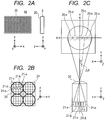
- FIGS. 2A to 2C are diagrams for describing a main portion of the photographing optical system in the present embodiment. In the diagrams, portions similar to those in FIG. 1 are designated by the same reference numerals.
- the MLA 14 is arranged near the image pickup plane of the photographing optical system 3 and a plurality of pixels of the imaging element 6 are made to correspond to one ML constructing the MLA.
- FIG. 2A is a diagram schematically illustrating a relation between the imaging element 6 and the MLA 14.
- FIG. 2B is a schematic diagram illustrating a correspondence between pixels 21 of the imaging element 6 and the MLA 14.
- FIG. 2C is a diagram illustrating a situation where the pixels arranged in correspondence to the MLA 14 are made to correspond to a specific pupil area by the MLA 14.
- FIG. 2A schematically illustrates an external appearance in the case where the imaging apparatus is viewed from its side and the MLA 14 is viewed from its front.
- Each ML 20 of the MLA 14 is arranged so as to cover the pixel on the imaging element 6 when it is viewed from the front side of the imaging apparatus.
- each ML constructing the MLA 14 is largely illustrated in FIG. 2A so as to be easily recognized visually, actually, each ML has a size which is a few times as large as the pixel. The actual size will be described with reference to FIG. 2B .
- FIG. 2B is a partially enlarged diagram of the diagram when viewed from the front side of the imaging apparatus of FIG. 2A .
- Lattice-shaped frames illustrated in FIG. 2B show each pixel 21 of the imaging element 6.
- Each ML 20 constructing the MLA 14 is shown by a bold circle.
- a predetermined number of pixels are allocated to one ML.
- FIG. 2C is a diagram of the imaging element 6 in the case where it is cut so as to contain an optical axis of the ML so that a longitudinal direction of the sensor is set to a lateral direction in the diagram.
- pixels 21-a, 21-b, 21-c, 21-d, and 21-e (one photoelectric conversion unit) of the imaging element 6 are illustrated.
- a diagram shown in an upward position in FIG. 2C indicates an exit pupil plane of the photographing optical system 3.
- the exit pupil plane X-Y plane
- FIG. 2C to simplify the description, a one-dimensional projection/signal processing will be described. In the actual apparatus, it can be easily expanded to two dimensions.
- each pixel is designed so as to be conjugate by the ML 20 with a specific exit pupil area on the exit pupil plane of the photographing optical system 3.
- FIG. 2C each pixel is designed so as to be conjugate by the ML 20 with a specific exit pupil area on the exit pupil plane of the photographing optical system 3.
- an area 25-a corresponds to the pixel 21-a
- an area 25-b corresponds to the pixel 21-b
- an area 25-c corresponds to the pixel 21-c
- an area 25-d corresponds to the pixel 21-d
- an area 25-e corresponds to the pixel 21-e, respectively. That is, only the ray of light which passes through the area 25-a on the exit pupil plane of the photographing optical system 3 enters the pixel 21-a. This is true of the other pixels. Consequently, the angle information of the object light can be obtained from the positional relation between the passing area on the pupil plane and the pixel on the imaging element 6.
- the pixel pitch is determined in dependence on a shape of the imaging element 6. ⁇ is determined by a range where an angle of the ray of light is obtained and the angle division number Ne. That is, those parameters are determined only by a physical structure (structure of the imaging element 6 and the ML 20).
- an angle of incidence of the ray of light can be specified by using the MLA. That is, by picking up the object image by using the optical system in FIGS. 2A to 2C , the angle information can be obtained in addition to the position of the incident light.
- the imaging apparatus which can obtain the light field information is generally called a "light field camera” or “plenoptic camera”.
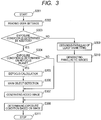
- FIG. 3 illustrates a flowchart for the determining operation of the exposure condition in the imaging apparatus according to the present embodiment.
- the operation shown in the present embodiment will be sequentially described with reference to the flowchart of FIG. 3 .
- the operation according to the flowchart of FIG. 3 is executed by a method whereby the camera system control unit 5 controls each unit.
- step S301 the camera system control unit 5 starts the operation.
- the operation is started by using an output of the operation detection unit 10 or a time as a trigger.
- step S302 the camera system control unit 5 reads settings determined by a user setting unit. Those settings are used as a ground of a branch judgment in step S303 or S304, which will be described hereinafter.
- a branch judgment for example, in the photographing, information showing whether the user wants to perform the photographing at a continuous photographing speed-priority, wants to output a refocus image, wants to preferentially perform an anti noise scheme (noise reduction) due to vignetting, or the like is held as setting data of a setting data unit.
- step S303 or S304 is the branch judgment about a technical construction to which the construction of the present embodiment is reflected, an actual interface does not relate to such a construction but may correspond to a function of the camera.
- an expression which can be easily understood as a function by the user such as "a priority is given to the continuous photographing speed” instead of an expression such as "an exposure is set on the basis of an added image”.
- the camera system control unit 5 and the image processing unit 7 detect objects on the basis of the pixel data which is previously obtained and inform the detected object on a display screen, and the user selects one or a plurality of objects in which there is a possibility that they will be refocused later.
- a weight is added to signals from the pixels constructing each object on an in-focus plane so that the exposure is properly performed on the refocus plane which is in-focused onto the selected one or a plurality of objects, and the exposure condition is determined.
- the user inputs and sets his wishes about whether or not he wants to change the viewpoint later, thereby evaluating that the image of which viewpoint is important in accordance with the number of detected objects and their positions and orientations, a weight is added to signals from the pixels constructing the image of the important viewpoint, and the exposure condition is determined.
- step S303 on the basis of the user settings which are read out in step S302, the camera system control unit 5 discriminates whether or not the exposure condition is determined on the basis of an addition signal (unit pixel data) or the exposure condition is determined on the basis of each parallactic image.
- step S304 follows.
- step S309 follows.
- a method of determining the exposure condition is not limited to such a method but the exposure condition may be determined in consideration of both of an added signal and a parallax signal.
- step S304 the camera system control unit 5 discriminates whether or not the exposure condition is obtained by a refocus plane.
- a refocus plane According to Ren Ng, et al., "Light Field Photography with a Hand-held Plenoptic Camera", 2005, Computer Science Technical Report CTSR , the foregoing imaging apparatus according to the embodiment can generate the pixel data which can be refocused. Since a refocusing method and the like have been disclosed in the prior art documents, their description is omitted here.
- the imaging apparatus has the following three exposure modes. That is, in the branch of steps S303 and S304, a case where the processing routine passes through step S309 corresponds to a first exposure mode, a case where the processing routine passes through step S304 ⁇ step S307 corresponds to a second exposure mode, and a case where the processing routine passes through step S304 ⁇ step S305 corresponds to a third exposure mode. In the present embodiment, those three exposure modes are selectively used in accordance with the user settings.
- the parallactic images are added and read out at the time of reading-out and the exposure condition is determined on the basis of the added image.
- the read-out and the continuous photographing can be performed at a high speed while suppressing a saturation of the added image (each parallactic image is based on the under exposure condition). In such a case, it is sufficient to use the second exposure mode.
- the parallactic images are read out separately at the time of reading-out and the exposure condition is determined on the basis of each parallactic image.
- the noises can be reduced by the addition combination after the reading-out while suppressing the saturation of the parallactic images (since the added image is based on the over exposure condition, there is a possibility of saturation). In such a case, it is sufficient to use the first exposure mode.
- the functions such as continuous photographing speed, noise reduction, and output of a final image in the refocus serving as judgment references in the determination of the exposure condition as mentioned above have been mentioned above as one example.
- the invention is not limited to them but it is sufficient to properly select the exposure mode in accordance with the function which the user wants to realize or the photographing settings.
- the user settings are confirmed in step S302 and the exposure condition suitable to a convenient reading method is determined.
- the imaging apparatus Since the imaging apparatus according to the embodiment generates the pixel data which can be refocused, such a system that a part of the focus adjustment function is performed by an image processing is also considered.
- the exposure condition is obtained by adding the signal of the imaging element 6 as it is (without refocusing), there is a case where its result does not become proper.
- the exposure condition is obtained by adding the signal of the imaging element 6 as it is (without refocusing)
- a small and light bright spot exists within a range of determining the exposure condition, there is a large change in brightness distribution between a defocus state and an in-focus state. In the in-focus case, the bright spot portion is observed as a very light area.
- step S304 in accordance with the user settings about whether or not the user makes the focus adjustment by the refocus effective. If the focus adjustment by the refocus is made effective, step S305 follows. If the focus adjustment by the refocus is made ineffective, a refocus amount is set to 0 and step S307 follows.
- step S305 a defocus amount is calculated. This processing is substantially the same as a technique called "focus detection". By calculating the defocus amount, a deviation amount of the focus to the principal object is quantitatively grasped.
- the camera system control unit 5 detects the principal object. It is sufficient to determine the object by the detection of the object from the image, an evaluation amount at the time of calculation of the defocus amount in step S305, or the like.
- the object detection from the image is well known as a face detection or the like.
- a position (depth) where the object exists can be known by steps S305 and S306 and an amount by which the image should be refocused is determined.
- step S307 the camera system control unit 5 generates an image on a plane corresponding to the refocus amount. Since the light field information has such a format that it is difficult for the user intuitively recognize it as it is, it is necessary to develop the image so that it can be handled in substantially the same manner as that of an ordinary image. "develop” mentioned here denotes such a processing operation that an operation to generate a re-formed image at an arbitrary refocus position from the light field information is executed to the pixel data.
- Step S307 relates to the operation to perform such a development and is a specific operation which is executed by an image generation unit in the camera system control unit 5. It is assumed that the user can set the refocus plane in the imaging apparatus according to the embodiment by a user setting unit.
- Step S309 is a specific operation of a vignetting calculation unit in the camera system control unit 5, and a pixel (parallactic pixel) of the least vignetting is obtained.
- the operation of the vignetting calculation unit will be described hereinafter with reference to FIGS. 4A to 4E .
- step S310 the camera system control unit 5 generates parallactic images by the pixel selected in step S309.
- step S308 the exposure condition is determined on the basis of the image obtained in step S307 or S310.
- the processing routine is finished in step S311.
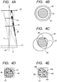
- FIG. 4A schematically illustrates relations among the imaging element 6, an iris 43, various kinds of lens frames 42 and 44, and the vignetting.
- the lens frame is a part to perform a holding or the like of the lens, so that the lens frame may generally an edge plane which restricts the light rays in accordance with an image height although it does not restrict the light rays at a center 40 of picture plane.
- FIG. 4B is a diagram illustrating positional relations among the iris 43 and various kinds of lens frames 42 and 44 at the center 40 of picture plane.
- FIG. 4C is a diagram illustrating positional relations among the iris 43 and various kinds of lens frames 42 and 44 at one point 41 on the imaging element 6.
- FIG. 4D and 4E are diagrams illustrating a correspondence between image pickup pixels and a vignetting in a state where there is the vignetting as illustrated in FIG. 4C , when viewed from a front side of the imaging apparatus in a manner similar to FIG. 2B .
- FIG. 4A a bold straight line showing the iris 43 one-dimensionally illustrates a size of aperture. Although the actual iris is almost circular, it is sufficient to consider that its diameter is schematically illustrated. This is true of the lens frames 42 and 44. When viewed from the center 40 of picture plane, as to the light ray directing toward the iris 43, no vignetting is caused by the lens frames 42 and 44. Such a case is illustrated in FIG. 4B.
- FIG. 4B FIG.
- FIG. 4B is a diagram in the case where the iris 43 and the lens frames 42 and 44 are projected to the plane of the iris 43 for the center 40 of picture plane. At this time, since the iris 43 and the lens frames 42 and 44 form concentric circles and a diameter of the iris 43 is smallest, it will be understood that no vignetting is caused by the lens frames 42 and 44.
- FIG. 4C is a diagram illustrating a case where the iris 43 and the lens frames 42 and 44 are projected to the plane of the iris 43 for the point 41. It will be understood that the vignetting is caused by the lens frame 44.
- factors which determine the state of vignetting are dominated by a pupil distance, a pupil diameter, an image height, a distance of the lens frame, a diameter of the lens frame, and the like serving as physical factors constructing the photographing optical system.
- the pupil distance is a distance between the imaging element 6 and the iris 43 in FIG. 4A .
- the pupil diameter is an F number and is a width of iris 43 in FIG. 4A .
- the image height is a position which is expressed by a comparison between the center 40 of picture plane and the point 41 on the imaging element 6 in FIG. 4A .
- the distance of the lens frame is a distance between the imaging element 6 and each of the lens frames 42 and 44 in FIG. 4A .
- the diameter of the lens frame is a width of each of the lens frames 42 and 44 in FIG. 4A .
- the state of vignetting on the pupil plane is determined as illustrated in FIG. 4C .
- the pixel in which the vignetting occurred can be specified in the unit pixel (5 rows ⁇ 5 columns) corresponding to one ML, the parallactic images in which there is no influence by the vignetting can be generated.
- a pixel 46 when there is a vignetting, a pixel (parallax) in which the rays of light which enter are largely restricted exists.
- a pixel 46 is in a state where there is no vignetting and an aperture ratio is equal to 100%. It is defined that the aperture ratio is a ratio of an area where no vignetting occurs when the pixel is projected to the pupil plane to the pixel area.
- the aperture ratio is a ratio of an area where no vignetting occurs when the pixel is projected to the pupil plane to the pixel area.
- the aperture ratio when an attention is paid to a pixel 47, although the aperture ratio ought to be equal to 100% in the state where there is no vignetting, a large vignetting exists in FIG. 4D .
- the exposure condition is determined on the basis of the pixel in which the vignetting exists like a pixel 47, there is a risk that the pixel 46 having no vignetting is saturated. If the exposure condition is determined on the basis of the pixel 46 having no vignetting, the saturation can be avoided.
- a method whereby a state of vignetting is presumed to use the pixel having the vignetting is also considered and the limitation of the parallactic image by step S309 is not always necessary.
- the noises and an error since only a small amount of light rays enters the pixel having a large vignetting, it is liable to be influenced by the noises and an error also occurs in the presumption of the vignetting state due to a dimensional error. That is, since such a method is influenced by an error of parts and the noises of the signal, it is not suitable to stably determine the exposure condition. It is, therefore, desirable to use the pixel in which a vignetting is small.
- a pixel (parallax) having the least vignetting is denoted with a reference numeral 48.
- a vignetting of each of other pixels 49a, 49b, and 49c is larger than that of the pixel 48 due to the lens frame 44. In the example of FIG. 4E , it is sufficient to select the pixel 48.
- the vignetting calculation unit calculates the vignetting of each pixel (parallax) from the information such as pupil distance, pupil diameter, image height, distance of the lens frame, diameter of the lens frame, and the like obtained by the communication or the like.
- the second exposure mode is set and the exposure condition is determined on the basis of the added image (predetermined image).
- the first exposure mode is set and the exposure condition is determined on the basis of each parallactic image (predetermined image).
- the third exposure mode is set and the exposure condition is determined on the basis of the added image (re-formed image).
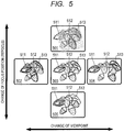
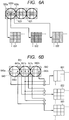
- FIG. 5 illustrates five kinds of images 501, 502, 503, 504, and 505 generated by processing an image pickup signal obtained by the exposure of one time.
- Objects 511, 512, and 513 exist sequentially in those images from the side near the imaging apparatus, respectively.
- a set of the images 501, 503, and 505 is a combination of the images which are obtained after the focus position is changed.
- an in-focus object is an object 511 in the image 501
- an in-focus object is an object 512 in the image 503
- an in-focus object is an object 513 in the image 505, respectively.
- the positions of the objects displayed in each image are not changed. Those images are effective for producing a new image expression by refocus, for example, or the like.
- FIG. 6A schematically illustrates the construction of the image processing in the case of obtaining the images in which the viewpoint is changed.
- FIG. 6B schematically illustrates the construction of the image processing in the case of obtaining the images in which the focus position is changed.
- FIGS. 6A and 6B Three circles and lattices illustrated at upper stages in FIGS. 6A and 6B show microlenses and imaging elements viewed from the front side of the element in a manner similar to FIG. 2B .
- microlenses 620, 640, 641, and 642 pixels 620a, 620b, and 620c under the microlens 620, images 631, 632, and 633 of different viewpoints, and pixels 640a and 640c under the microlens 640 are illustrated, respectively.
- Pixels 641a, 641b, and 641c under the microlens 641, pixels 642a and 642c under the microlens 642, and images 651, 652, and 653 of different focus positions are illustrated, respectively.
- the images of different viewpoints can be generated by collecting the pixels in which the relative positions are equal for each microlens.
- the images 631, 632, and 633 are images obtained by observing the object from different positions.
- the parallactic images are generated only by rearranging the pixel signals and there is no need to execute an arithmetic operation such as an addition or the like.
- step S309 a parallax of the least vignetting is obtained in step S309 and the parallactic images of the parallax selected in step S309 are generated in step S310.
- this corresponds to a case where the pixel 620b locating at the center of the microlens 620 is selected and the pixels whose relative positions are equal are collected also for the other microlenses, and the image 632 is generated.
- step S308 the exposure condition is determined on the basis of the image 632. That is, the image 632 enters the proper exposure state.
- each parallactic image properly enters the exposure state or does not enter the exposure state which is fairly improper although the object is exposed by a slightly small exposure amount, a photographed image which can be directly provided to an application accompanied with a change of viewpoint can be obtained.
- FIG. 6B A construction for generating the images whose focus positions are changed will now be described with reference to FIG. 6B .
- a description will be made on the assumption that the adding direction is limited to one axis in the lateral direction in order to simplify the description. That is, although the light field information is expressed by four dimensions (two dimensions of the angle + two dimensions of the position), a description will be made here by using only two dimensions (one dimension of the angle and one dimension of the position in the lateral direction in FIG. 6B ) among the four dimensions.
- the images whose focus positions are changed can be generated.
- the images 651, 652, and 653 are images whose focus positions differ. If the object is in-focused, the light rays from the same point on the object are focused to the same point irrespective of the pupil areas where the light rays pass. This is what is called an "in-focus state".
- the image 652 is obtained also by arranging signals which are similarly generated with respect to the other microlenses.
- the image 652 is provided as an image (photographed image) in which the object which is in-focused by the microlens 641 is clearly seen. In the case of changing the focus position to a position different from the image 652, it is sufficient to change the phase to be added.
- the pixel 640a which is far to and exists on the left side of the adjacent microlens 640 and the pixel 642c on the right side of the adjacent microlens 642 are added to the pixel 641b existing at the center of the microlens 641.
- the image 651 is obtained by arranging signals in which the pixels having a similar phase relation are added also for the other microlenses.
- the image 651 becomes an image which is in-focused to a position different from the image 652.
- the image 653 is obtained by adding the pixels having phase relations such as 641b, 640c, and 642a.
- the images 653 and 651 become images (re-formed images) which are defocused in the opposite directions.
- the change of the focus position is accompanied with the addition of the pixels.
- the added image is generated in step S307, it corresponds to the image 652 in FIG. 6B .
- the processing routine advances from step S304 through steps S305 and S306, the refocus state where the principal object is in-focused is selected.
- any one of the images 651, 652, and 653 is selected in accordance with the focus state in step S307.
- the exposure condition is determined on the basis of the images 651, 652, and 653 in step S308. That is, the images 651, 652, and 653 are in the proper exposure state.
- the invention is made to determine whether or not any one of those states is set into the proper exposure state, and the exposure state is determined so that the image can be more easily provided in accordance with the function which is preferentially selected by the user.
- the imaging apparatus in which even if the apparatus is in a state where there is a vignetting of the photographing optical system, the exposure condition according to the photographing function which is preferentially set by the user can be determined can be provided.
- Embodiment(s) of the present invention can also be realized by a computer of a system or apparatus that reads out and executes computer executable instructions (e.g., one or more programs) recorded on a storage medium (which may also be referred to more fully as a 'non-transitory computer-readable storage medium') to perform the functions of one or more of the above-described embodiment(s) and/or that includes one or more circuits (e.g., application specific integrated circuit (ASIC)) for performing the functions of one or more of the above-described embodiment(s), and by a method performed by the computer of the system or apparatus by, for example, reading out and executing the computer executable instructions from the storage medium to perform the functions of one or more of the above-described embodiment(s) and/or controlling the one or more circuits to perform the functions of one or more of the above-described embodiment(s).
- computer executable instructions e.g., one or more programs
- a storage medium which may also be referred to more fully as
- the computer may comprise one or more processors (e.g., central processing unit (CPU), micro processing unit (MPU)) and may include a network of separate computers or separate processors to read out and execute the computer executable instructions.
- the computer executable instructions may be provided to the computer, for example, from a network or the storage medium.
- the storage medium may include, for example, one or more of a hard disk, a random-access memory (RAM), a read only memory (ROM), a storage of distributed computing systems, an optical disk (such as a compact disc (CD), digital versatile disc (DVD), or Blu-ray Disc (BD)TM), a flash memory device, a memory card, and the like. While the present invention has been described with reference to exemplary embodiments, it is to be understood that the invention is not limited to the disclosed exemplary embodiments.
Landscapes
- Engineering & Computer Science (AREA)
- Multimedia (AREA)
- Signal Processing (AREA)
- Studio Devices (AREA)
- Exposure Control For Cameras (AREA)
Applications Claiming Priority (2)
| Application Number | Priority Date | Filing Date | Title |
|---|---|---|---|
| JP2013220217 | 2013-10-23 | ||
| JP2014185232A JP6397281B2 (ja) | 2013-10-23 | 2014-09-11 | 撮像装置、その制御方法およびプログラム |
Publications (2)
| Publication Number | Publication Date |
|---|---|
| EP2866430A1 EP2866430A1 (en) | 2015-04-29 |
| EP2866430B1 true EP2866430B1 (en) | 2018-08-29 |
Family
ID=51794712
Family Applications (1)
| Application Number | Title | Priority Date | Filing Date |
|---|---|---|---|
| EP14003617.9A Active EP2866430B1 (en) | 2013-10-23 | 2014-10-23 | Imaging apparatus and its control method and program |
Country Status (5)
| Country | Link |
|---|---|
| US (1) | US9554054B2 (zh) |
| EP (1) | EP2866430B1 (zh) |
| JP (1) | JP6397281B2 (zh) |
| KR (1) | KR20150047112A (zh) |
| CN (1) | CN104580921B (zh) |
Families Citing this family (7)
| Publication number | Priority date | Publication date | Assignee | Title |
|---|---|---|---|---|
| JP6548367B2 (ja) * | 2014-07-16 | 2019-07-24 | キヤノン株式会社 | 画像処理装置、撮像装置、画像処理方法及びプログラム |
| JP6758946B2 (ja) | 2015-09-09 | 2020-09-23 | キヤノン株式会社 | 撮像装置及び再生装置 |
| US10001654B2 (en) * | 2016-07-25 | 2018-06-19 | Disney Enterprises, Inc. | Retroreflector display system for generating floating image effects |
| CN109937382B (zh) * | 2016-08-26 | 2020-12-18 | 华为技术有限公司 | 成像装置和成像方法 |
| JP2018050231A (ja) * | 2016-09-23 | 2018-03-29 | キヤノン株式会社 | 撮像装置、撮像方法および撮像制御プログラム |
| US10602051B2 (en) * | 2017-03-28 | 2020-03-24 | Canon Kabushiki Kaisha | Imaging apparatus, control method, and non-transitory storage medium |
| EP3422723B1 (en) | 2017-06-30 | 2023-04-26 | InterDigital VC Holdings, Inc. | Method for encoding and decoding at least one matrix of image views obtained from data acquired by a plenoptic camera, and corresponding electronic devices |
Family Cites Families (16)
| Publication number | Priority date | Publication date | Assignee | Title |
|---|---|---|---|---|
| EP1941314A4 (en) | 2005-10-07 | 2010-04-14 | Univ Leland Stanford Junior | ARRANGEMENTS AND APPROACHES FOR MICROSCOPY |
| JP2008070510A (ja) | 2006-09-13 | 2008-03-27 | Pentax Corp | 撮像装置 |
| JP4867554B2 (ja) | 2006-09-29 | 2012-02-01 | カシオ計算機株式会社 | 電子カメラ、撮像制御プログラム及び撮像制御方法 |
| JP5159515B2 (ja) * | 2008-08-26 | 2013-03-06 | キヤノン株式会社 | 画像処理装置およびその制御方法 |
| JP5424679B2 (ja) * | 2009-03-18 | 2014-02-26 | キヤノン株式会社 | 撮像装置及び信号処理装置 |
| JP5213813B2 (ja) * | 2009-08-18 | 2013-06-19 | キヤノン株式会社 | 撮像装置及び撮像装置の制御方法 |
| JP2011182304A (ja) * | 2010-03-03 | 2011-09-15 | Renesas Electronics Corp | 撮像装置及びその制御方法 |
| JP5457240B2 (ja) | 2010-03-18 | 2014-04-02 | 富士フイルム株式会社 | 立体撮像装置 |
| JP5411842B2 (ja) | 2010-12-07 | 2014-02-12 | シャープ株式会社 | 撮像装置 |
| US20140176592A1 (en) * | 2011-02-15 | 2014-06-26 | Lytro, Inc. | Configuring two-dimensional image processing based on light-field parameters |
| JP5473977B2 (ja) * | 2011-04-14 | 2014-04-16 | キヤノン株式会社 | 撮像装置およびカメラシステム |
| JP5618943B2 (ja) | 2011-08-19 | 2014-11-05 | キヤノン株式会社 | 画像処理方法、撮像装置、画像処理装置、および、画像処理プログラム |
| JP6095266B2 (ja) * | 2012-01-13 | 2017-03-15 | キヤノン株式会社 | 画像処理装置及びその制御方法 |
| JP5898501B2 (ja) * | 2012-01-13 | 2016-04-06 | キヤノン株式会社 | 画像処理装置、撮像装置、制御方法、プログラム及び記録媒体 |
| US8948545B2 (en) * | 2012-02-28 | 2015-02-03 | Lytro, Inc. | Compensating for sensor saturation and microlens modulation during light-field image processing |
| WO2013147198A1 (ja) * | 2012-03-30 | 2013-10-03 | 株式会社ニコン | 撮像装置および撮像素子 |
-
2014
- 2014-09-11 JP JP2014185232A patent/JP6397281B2/ja active Active
- 2014-10-20 US US14/518,230 patent/US9554054B2/en active Active
- 2014-10-23 CN CN201410571902.0A patent/CN104580921B/zh active Active
- 2014-10-23 EP EP14003617.9A patent/EP2866430B1/en active Active
- 2014-10-23 KR KR1020140143897A patent/KR20150047112A/ko not_active Application Discontinuation
Also Published As
| Publication number | Publication date |
|---|---|
| JP6397281B2 (ja) | 2018-09-26 |
| EP2866430A1 (en) | 2015-04-29 |
| CN104580921B (zh) | 2018-04-03 |
| US20150109522A1 (en) | 2015-04-23 |
| KR20150047112A (ko) | 2015-05-04 |
| US9554054B2 (en) | 2017-01-24 |
| JP2015109635A (ja) | 2015-06-11 |
| CN104580921A (zh) | 2015-04-29 |
Similar Documents
| Publication | Publication Date | Title |
|---|---|---|
| EP2866430B1 (en) | Imaging apparatus and its control method and program | |
| US10397547B2 (en) | Stereoscopic image pickup unit, image pickup device, picture processing method, control method, and program utilizing diaphragm to form pair of apertures | |
| US10021309B2 (en) | Image recording apparatus and image reproducing apparatus | |
| EP2590023B1 (en) | Imaging device and imaging method | |
| US20160119550A1 (en) | Image processing device, image capturing device including image processing device, image processing method, and program | |
| JP5421829B2 (ja) | 撮像装置 | |
| US10511781B2 (en) | Image pickup apparatus, control method for image pickup apparatus | |
| US9208569B2 (en) | Image processing apparatus and control method thereof capable of performing refocus calculation processing for light field data | |
| US9924155B2 (en) | Imaging apparatus and method for controlling same | |
| US20130107019A1 (en) | Imaging device, image processing device and image processing method | |
| JP5757129B2 (ja) | 撮像装置、絞り制御方法およびプログラム | |
| US20130083169A1 (en) | Image capturing apparatus, image processing apparatus, image processing method and program | |
| EP2590024A1 (en) | Imaging apparatus and imaging method | |
| JP7195790B2 (ja) | 撮像装置及びその制御方法 | |
| US20180109720A1 (en) | Image processing apparatus, image processing method, and storage medium | |
| JP5207893B2 (ja) | 撮像装置及びその制御方法 | |
| JP6071748B2 (ja) | 撮像装置およびその制御方法 | |
| US20220385875A1 (en) | Device, capturing device, control method, and storage medium | |
| US20240015399A1 (en) | Image processing apparatus, display apparatus, and image processing method | |
| JP5853510B2 (ja) | 撮像装置 | |
| JP6858059B2 (ja) | 撮像装置及びその制御方法、プログラム、記憶媒体 | |
| JP2015154112A (ja) | 画像処理装置、その制御方法およびプログラム | |
| JP2014095874A (ja) | 撮像装置および撮像装置の制御方法 |
Legal Events
| Date | Code | Title | Description |
|---|---|---|---|
| PUAI | Public reference made under article 153(3) epc to a published international application that has entered the european phase |
Free format text: ORIGINAL CODE: 0009012 |
|
| 17P | Request for examination filed |
Effective date: 20141023 |
|
| AK | Designated contracting states |
Kind code of ref document: A1 Designated state(s): AL AT BE BG CH CY CZ DE DK EE ES FI FR GB GR HR HU IE IS IT LI LT LU LV MC MK MT NL NO PL PT RO RS SE SI SK SM TR |
|
| AX | Request for extension of the european patent |
Extension state: BA ME |
|
| R17P | Request for examination filed (corrected) |
Effective date: 20151029 |
|
| RBV | Designated contracting states (corrected) |
Designated state(s): AL AT BE BG CH CY CZ DE DK EE ES FI FR GB GR HR HU IE IS IT LI LT LU LV MC MK MT NL NO PL PT RO RS SE SI SK SM TR |
|
| 17Q | First examination report despatched |
Effective date: 20170328 |
|
| GRAP | Despatch of communication of intention to grant a patent |
Free format text: ORIGINAL CODE: EPIDOSNIGR1 |
|
| INTG | Intention to grant announced |
Effective date: 20180312 |
|
| RAP1 | Party data changed (applicant data changed or rights of an application transferred) |
Owner name: CANON KABUSHIKI KAISHA |
|
| GRAS | Grant fee paid |
Free format text: ORIGINAL CODE: EPIDOSNIGR3 |
|
| GRAA | (expected) grant |
Free format text: ORIGINAL CODE: 0009210 |
|
| AK | Designated contracting states |
Kind code of ref document: B1 Designated state(s): AL AT BE BG CH CY CZ DE DK EE ES FI FR GB GR HR HU IE IS IT LI LT LU LV MC MK MT NL NO PL PT RO RS SE SI SK SM TR |
|
| REG | Reference to a national code |
Ref country code: GB Ref legal event code: FG4D |
|
| REG | Reference to a national code |
Ref country code: CH Ref legal event code: EP |
|
| REG | Reference to a national code |
Ref country code: AT Ref legal event code: REF Ref document number: 1036563 Country of ref document: AT Kind code of ref document: T Effective date: 20180915 |
|
| REG | Reference to a national code |
Ref country code: IE Ref legal event code: FG4D |
|
| REG | Reference to a national code |
Ref country code: DE Ref legal event code: R096 Ref document number: 602014031173 Country of ref document: DE |
|
| REG | Reference to a national code |
Ref country code: NL Ref legal event code: MP Effective date: 20180829 |
|
| REG | Reference to a national code |
Ref country code: LT Ref legal event code: MG4D |
|
| PG25 | Lapsed in a contracting state [announced via postgrant information from national office to epo] |
Ref country code: FI Free format text: LAPSE BECAUSE OF FAILURE TO SUBMIT A TRANSLATION OF THE DESCRIPTION OR TO PAY THE FEE WITHIN THE PRESCRIBED TIME-LIMIT Effective date: 20180829 Ref country code: SE Free format text: LAPSE BECAUSE OF FAILURE TO SUBMIT A TRANSLATION OF THE DESCRIPTION OR TO PAY THE FEE WITHIN THE PRESCRIBED TIME-LIMIT Effective date: 20180829 Ref country code: IS Free format text: LAPSE BECAUSE OF FAILURE TO SUBMIT A TRANSLATION OF THE DESCRIPTION OR TO PAY THE FEE WITHIN THE PRESCRIBED TIME-LIMIT Effective date: 20181229 Ref country code: RS Free format text: LAPSE BECAUSE OF FAILURE TO SUBMIT A TRANSLATION OF THE DESCRIPTION OR TO PAY THE FEE WITHIN THE PRESCRIBED TIME-LIMIT Effective date: 20180829 Ref country code: NL Free format text: LAPSE BECAUSE OF FAILURE TO SUBMIT A TRANSLATION OF THE DESCRIPTION OR TO PAY THE FEE WITHIN THE PRESCRIBED TIME-LIMIT Effective date: 20180829 Ref country code: LT Free format text: LAPSE BECAUSE OF FAILURE TO SUBMIT A TRANSLATION OF THE DESCRIPTION OR TO PAY THE FEE WITHIN THE PRESCRIBED TIME-LIMIT Effective date: 20180829 Ref country code: GR Free format text: LAPSE BECAUSE OF FAILURE TO SUBMIT A TRANSLATION OF THE DESCRIPTION OR TO PAY THE FEE WITHIN THE PRESCRIBED TIME-LIMIT Effective date: 20181130 Ref country code: NO Free format text: LAPSE BECAUSE OF FAILURE TO SUBMIT A TRANSLATION OF THE DESCRIPTION OR TO PAY THE FEE WITHIN THE PRESCRIBED TIME-LIMIT Effective date: 20181129 Ref country code: BG Free format text: LAPSE BECAUSE OF FAILURE TO SUBMIT A TRANSLATION OF THE DESCRIPTION OR TO PAY THE FEE WITHIN THE PRESCRIBED TIME-LIMIT Effective date: 20181129 |
|
| REG | Reference to a national code |
Ref country code: AT Ref legal event code: MK05 Ref document number: 1036563 Country of ref document: AT Kind code of ref document: T Effective date: 20180829 |
|
| PG25 | Lapsed in a contracting state [announced via postgrant information from national office to epo] |
Ref country code: AL Free format text: LAPSE BECAUSE OF FAILURE TO SUBMIT A TRANSLATION OF THE DESCRIPTION OR TO PAY THE FEE WITHIN THE PRESCRIBED TIME-LIMIT Effective date: 20180829 Ref country code: HR Free format text: LAPSE BECAUSE OF FAILURE TO SUBMIT A TRANSLATION OF THE DESCRIPTION OR TO PAY THE FEE WITHIN THE PRESCRIBED TIME-LIMIT Effective date: 20180829 Ref country code: LV Free format text: LAPSE BECAUSE OF FAILURE TO SUBMIT A TRANSLATION OF THE DESCRIPTION OR TO PAY THE FEE WITHIN THE PRESCRIBED TIME-LIMIT Effective date: 20180829 |
|
| PG25 | Lapsed in a contracting state [announced via postgrant information from national office to epo] |
Ref country code: AT Free format text: LAPSE BECAUSE OF FAILURE TO SUBMIT A TRANSLATION OF THE DESCRIPTION OR TO PAY THE FEE WITHIN THE PRESCRIBED TIME-LIMIT Effective date: 20180829 Ref country code: ES Free format text: LAPSE BECAUSE OF FAILURE TO SUBMIT A TRANSLATION OF THE DESCRIPTION OR TO PAY THE FEE WITHIN THE PRESCRIBED TIME-LIMIT Effective date: 20180829 Ref country code: PL Free format text: LAPSE BECAUSE OF FAILURE TO SUBMIT A TRANSLATION OF THE DESCRIPTION OR TO PAY THE FEE WITHIN THE PRESCRIBED TIME-LIMIT Effective date: 20180829 Ref country code: EE Free format text: LAPSE BECAUSE OF FAILURE TO SUBMIT A TRANSLATION OF THE DESCRIPTION OR TO PAY THE FEE WITHIN THE PRESCRIBED TIME-LIMIT Effective date: 20180829 Ref country code: CZ Free format text: LAPSE BECAUSE OF FAILURE TO SUBMIT A TRANSLATION OF THE DESCRIPTION OR TO PAY THE FEE WITHIN THE PRESCRIBED TIME-LIMIT Effective date: 20180829 Ref country code: IT Free format text: LAPSE BECAUSE OF FAILURE TO SUBMIT A TRANSLATION OF THE DESCRIPTION OR TO PAY THE FEE WITHIN THE PRESCRIBED TIME-LIMIT Effective date: 20180829 Ref country code: RO Free format text: LAPSE BECAUSE OF FAILURE TO SUBMIT A TRANSLATION OF THE DESCRIPTION OR TO PAY THE FEE WITHIN THE PRESCRIBED TIME-LIMIT Effective date: 20180829 |
|
| PG25 | Lapsed in a contracting state [announced via postgrant information from national office to epo] |
Ref country code: SM Free format text: LAPSE BECAUSE OF FAILURE TO SUBMIT A TRANSLATION OF THE DESCRIPTION OR TO PAY THE FEE WITHIN THE PRESCRIBED TIME-LIMIT Effective date: 20180829 Ref country code: DK Free format text: LAPSE BECAUSE OF FAILURE TO SUBMIT A TRANSLATION OF THE DESCRIPTION OR TO PAY THE FEE WITHIN THE PRESCRIBED TIME-LIMIT Effective date: 20180829 Ref country code: SK Free format text: LAPSE BECAUSE OF FAILURE TO SUBMIT A TRANSLATION OF THE DESCRIPTION OR TO PAY THE FEE WITHIN THE PRESCRIBED TIME-LIMIT Effective date: 20180829 |
|
| REG | Reference to a national code |
Ref country code: CH Ref legal event code: PL Ref country code: DE Ref legal event code: R097 Ref document number: 602014031173 Country of ref document: DE |
|
| REG | Reference to a national code |
Ref country code: BE Ref legal event code: MM Effective date: 20181031 |
|
| PG25 | Lapsed in a contracting state [announced via postgrant information from national office to epo] |
Ref country code: LU Free format text: LAPSE BECAUSE OF NON-PAYMENT OF DUE FEES Effective date: 20181023 Ref country code: MC Free format text: LAPSE BECAUSE OF FAILURE TO SUBMIT A TRANSLATION OF THE DESCRIPTION OR TO PAY THE FEE WITHIN THE PRESCRIBED TIME-LIMIT Effective date: 20180829 |
|
| PLBE | No opposition filed within time limit |
Free format text: ORIGINAL CODE: 0009261 |
|
| STAA | Information on the status of an ep patent application or granted ep patent |
Free format text: STATUS: NO OPPOSITION FILED WITHIN TIME LIMIT |
|
| REG | Reference to a national code |
Ref country code: IE Ref legal event code: MM4A |
|
| 26N | No opposition filed |
Effective date: 20190531 |
|
| PG25 | Lapsed in a contracting state [announced via postgrant information from national office to epo] |
Ref country code: SI Free format text: LAPSE BECAUSE OF FAILURE TO SUBMIT A TRANSLATION OF THE DESCRIPTION OR TO PAY THE FEE WITHIN THE PRESCRIBED TIME-LIMIT Effective date: 20180829 Ref country code: FR Free format text: LAPSE BECAUSE OF NON-PAYMENT OF DUE FEES Effective date: 20181029 Ref country code: CH Free format text: LAPSE BECAUSE OF NON-PAYMENT OF DUE FEES Effective date: 20181031 Ref country code: BE Free format text: LAPSE BECAUSE OF NON-PAYMENT OF DUE FEES Effective date: 20181031 Ref country code: LI Free format text: LAPSE BECAUSE OF NON-PAYMENT OF DUE FEES Effective date: 20181031 |
|
| PG25 | Lapsed in a contracting state [announced via postgrant information from national office to epo] |
Ref country code: IE Free format text: LAPSE BECAUSE OF NON-PAYMENT OF DUE FEES Effective date: 20181023 |
|
| PG25 | Lapsed in a contracting state [announced via postgrant information from national office to epo] |
Ref country code: MT Free format text: LAPSE BECAUSE OF NON-PAYMENT OF DUE FEES Effective date: 20181023 |
|
| PG25 | Lapsed in a contracting state [announced via postgrant information from national office to epo] |
Ref country code: TR Free format text: LAPSE BECAUSE OF FAILURE TO SUBMIT A TRANSLATION OF THE DESCRIPTION OR TO PAY THE FEE WITHIN THE PRESCRIBED TIME-LIMIT Effective date: 20180829 |
|
| PG25 | Lapsed in a contracting state [announced via postgrant information from national office to epo] |
Ref country code: PT Free format text: LAPSE BECAUSE OF FAILURE TO SUBMIT A TRANSLATION OF THE DESCRIPTION OR TO PAY THE FEE WITHIN THE PRESCRIBED TIME-LIMIT Effective date: 20180829 |
|
| PG25 | Lapsed in a contracting state [announced via postgrant information from national office to epo] |
Ref country code: HU Free format text: LAPSE BECAUSE OF FAILURE TO SUBMIT A TRANSLATION OF THE DESCRIPTION OR TO PAY THE FEE WITHIN THE PRESCRIBED TIME-LIMIT; INVALID AB INITIO Effective date: 20141023 Ref country code: MK Free format text: LAPSE BECAUSE OF NON-PAYMENT OF DUE FEES Effective date: 20180829 Ref country code: CY Free format text: LAPSE BECAUSE OF FAILURE TO SUBMIT A TRANSLATION OF THE DESCRIPTION OR TO PAY THE FEE WITHIN THE PRESCRIBED TIME-LIMIT Effective date: 20180829 |
|
| REG | Reference to a national code |
Ref country code: DE Ref legal event code: R079 Ref document number: 602014031173 Country of ref document: DE Free format text: PREVIOUS MAIN CLASS: H04N0005217000 Ipc: H04N0023800000 |
|
| PGFP | Annual fee paid to national office [announced via postgrant information from national office to epo] |
Ref country code: GB Payment date: 20230920 Year of fee payment: 10 |
|
| PGFP | Annual fee paid to national office [announced via postgrant information from national office to epo] |
Ref country code: DE Payment date: 20230920 Year of fee payment: 10 |