EP2865978A1 - Verfahren zur Tieftemperaturzerlegung von Luft und Tieftemperatur-Luftzerlegungsanlage - Google Patents
Verfahren zur Tieftemperaturzerlegung von Luft und Tieftemperatur-Luftzerlegungsanlage Download PDFInfo
- Publication number
- EP2865978A1 EP2865978A1 EP20130005245 EP13005245A EP2865978A1 EP 2865978 A1 EP2865978 A1 EP 2865978A1 EP 20130005245 EP20130005245 EP 20130005245 EP 13005245 A EP13005245 A EP 13005245A EP 2865978 A1 EP2865978 A1 EP 2865978A1
- Authority
- EP
- European Patent Office
- Prior art keywords
- pressure column
- column
- low
- air separation
- strands
- Prior art date
- Legal status (The legal status is an assumption and is not a legal conclusion. Google has not performed a legal analysis and makes no representation as to the accuracy of the status listed.)
- Withdrawn
Links
- 238000000926 separation method Methods 0.000 title claims abstract description 47
- 238000000034 method Methods 0.000 title claims abstract description 15
- 238000004821 distillation Methods 0.000 claims abstract description 53
- IJGRMHOSHXDMSA-UHFFFAOYSA-N Atomic nitrogen Chemical compound N#N IJGRMHOSHXDMSA-UHFFFAOYSA-N 0.000 claims abstract description 38
- 238000001704 evaporation Methods 0.000 claims abstract description 25
- 230000008020 evaporation Effects 0.000 claims abstract description 24
- 239000003990 capacitor Substances 0.000 claims abstract description 21
- 239000007788 liquid Substances 0.000 claims abstract description 19
- 238000012856 packing Methods 0.000 claims abstract description 19
- 229910052757 nitrogen Inorganic materials 0.000 claims abstract description 16
- MYMOFIZGZYHOMD-UHFFFAOYSA-N Dioxygen Chemical compound O=O MYMOFIZGZYHOMD-UHFFFAOYSA-N 0.000 claims abstract description 14
- 229910001873 dinitrogen Inorganic materials 0.000 claims abstract description 6
- 229910001882 dioxygen Inorganic materials 0.000 claims abstract description 6
- 239000002184 metal Substances 0.000 claims abstract 3
- DOTMOQHOJINYBL-UHFFFAOYSA-N molecular nitrogen;molecular oxygen Chemical compound N#N.O=O DOTMOQHOJINYBL-UHFFFAOYSA-N 0.000 claims description 4
- 201000009240 nasopharyngitis Diseases 0.000 claims description 3
- 230000008016 vaporization Effects 0.000 abstract description 2
- 238000009834 vaporization Methods 0.000 abstract 1
- XKRFYHLGVUSROY-UHFFFAOYSA-N Argon Chemical compound [Ar] XKRFYHLGVUSROY-UHFFFAOYSA-N 0.000 description 28
- 229910052786 argon Inorganic materials 0.000 description 14
- QVGXLLKOCUKJST-UHFFFAOYSA-N atomic oxygen Chemical compound [O] QVGXLLKOCUKJST-UHFFFAOYSA-N 0.000 description 13
- 239000001301 oxygen Substances 0.000 description 13
- 229910052760 oxygen Inorganic materials 0.000 description 13
- 238000011084 recovery Methods 0.000 description 6
- 238000007906 compression Methods 0.000 description 5
- 230000006835 compression Effects 0.000 description 5
- 239000012530 fluid Substances 0.000 description 5
- 238000001816 cooling Methods 0.000 description 3
- 230000002349 favourable effect Effects 0.000 description 3
- 238000004140 cleaning Methods 0.000 description 2
- 238000010276 construction Methods 0.000 description 2
- 239000007789 gas Substances 0.000 description 2
- 238000004519 manufacturing process Methods 0.000 description 2
- 238000000746 purification Methods 0.000 description 2
- 238000010992 reflux Methods 0.000 description 2
- 241000883306 Huso huso Species 0.000 description 1
- 238000004887 air purification Methods 0.000 description 1
- 238000003889 chemical engineering Methods 0.000 description 1
- 238000009833 condensation Methods 0.000 description 1
- 230000005494 condensation Effects 0.000 description 1
- 238000000354 decomposition reaction Methods 0.000 description 1
- 230000001419 dependent effect Effects 0.000 description 1
- 230000000694 effects Effects 0.000 description 1
- 238000005265 energy consumption Methods 0.000 description 1
- 239000011552 falling film Substances 0.000 description 1
- 238000011049 filling Methods 0.000 description 1
- 238000009434 installation Methods 0.000 description 1
- 239000011810 insulating material Substances 0.000 description 1
- 238000009413 insulation Methods 0.000 description 1
- 239000000463 material Substances 0.000 description 1
- 239000002808 molecular sieve Substances 0.000 description 1
- 238000004172 nitrogen cycle Methods 0.000 description 1
- 229910052756 noble gas Inorganic materials 0.000 description 1
- 150000002835 noble gases Chemical class 0.000 description 1
- 238000005192 partition Methods 0.000 description 1
- 235000019362 perlite Nutrition 0.000 description 1
- 239000010451 perlite Substances 0.000 description 1
- 238000005057 refrigeration Methods 0.000 description 1
- URGAHOPLAPQHLN-UHFFFAOYSA-N sodium aluminosilicate Chemical compound [Na+].[Al+3].[O-][Si]([O-])=O.[O-][Si]([O-])=O URGAHOPLAPQHLN-UHFFFAOYSA-N 0.000 description 1
- 238000004781 supercooling Methods 0.000 description 1
- 238000011144 upstream manufacturing Methods 0.000 description 1
Images

Classifications
-
- F—MECHANICAL ENGINEERING; LIGHTING; HEATING; WEAPONS; BLASTING
- F25—REFRIGERATION OR COOLING; COMBINED HEATING AND REFRIGERATION SYSTEMS; HEAT PUMP SYSTEMS; MANUFACTURE OR STORAGE OF ICE; LIQUEFACTION SOLIDIFICATION OF GASES
- F25J—LIQUEFACTION, SOLIDIFICATION OR SEPARATION OF GASES OR GASEOUS OR LIQUEFIED GASEOUS MIXTURES BY PRESSURE AND COLD TREATMENT OR BY BRINGING THEM INTO THE SUPERCRITICAL STATE
- F25J3/00—Processes or apparatus for separating the constituents of gaseous or liquefied gaseous mixtures involving the use of liquefaction or solidification
- F25J3/02—Processes or apparatus for separating the constituents of gaseous or liquefied gaseous mixtures involving the use of liquefaction or solidification by rectification, i.e. by continuous interchange of heat and material between a vapour stream and a liquid stream
- F25J3/04—Processes or apparatus for separating the constituents of gaseous or liquefied gaseous mixtures involving the use of liquefaction or solidification by rectification, i.e. by continuous interchange of heat and material between a vapour stream and a liquid stream for air
- F25J3/04642—Recovering noble gases from air
- F25J3/04648—Recovering noble gases from air argon
- F25J3/04654—Producing crude argon in a crude argon column
- F25J3/04666—Producing crude argon in a crude argon column as a parallel working rectification column of the low pressure column in a dual pressure main column system
- F25J3/04672—Producing crude argon in a crude argon column as a parallel working rectification column of the low pressure column in a dual pressure main column system having a top condenser
- F25J3/04678—Producing crude argon in a crude argon column as a parallel working rectification column of the low pressure column in a dual pressure main column system having a top condenser cooled by oxygen enriched liquid from high pressure column bottoms
-
- F—MECHANICAL ENGINEERING; LIGHTING; HEATING; WEAPONS; BLASTING
- F25—REFRIGERATION OR COOLING; COMBINED HEATING AND REFRIGERATION SYSTEMS; HEAT PUMP SYSTEMS; MANUFACTURE OR STORAGE OF ICE; LIQUEFACTION SOLIDIFICATION OF GASES
- F25J—LIQUEFACTION, SOLIDIFICATION OR SEPARATION OF GASES OR GASEOUS OR LIQUEFIED GASEOUS MIXTURES BY PRESSURE AND COLD TREATMENT OR BY BRINGING THEM INTO THE SUPERCRITICAL STATE
- F25J3/00—Processes or apparatus for separating the constituents of gaseous or liquefied gaseous mixtures involving the use of liquefaction or solidification
- F25J3/02—Processes or apparatus for separating the constituents of gaseous or liquefied gaseous mixtures involving the use of liquefaction or solidification by rectification, i.e. by continuous interchange of heat and material between a vapour stream and a liquid stream
- F25J3/04—Processes or apparatus for separating the constituents of gaseous or liquefied gaseous mixtures involving the use of liquefaction or solidification by rectification, i.e. by continuous interchange of heat and material between a vapour stream and a liquid stream for air
- F25J3/04006—Providing pressurised feed air or process streams within or from the air fractionation unit
- F25J3/04078—Providing pressurised feed air or process streams within or from the air fractionation unit providing pressurized products by liquid compression and vaporisation with cold recovery, i.e. so-called internal compression
- F25J3/04084—Providing pressurised feed air or process streams within or from the air fractionation unit providing pressurized products by liquid compression and vaporisation with cold recovery, i.e. so-called internal compression of nitrogen
-
- F—MECHANICAL ENGINEERING; LIGHTING; HEATING; WEAPONS; BLASTING
- F25—REFRIGERATION OR COOLING; COMBINED HEATING AND REFRIGERATION SYSTEMS; HEAT PUMP SYSTEMS; MANUFACTURE OR STORAGE OF ICE; LIQUEFACTION SOLIDIFICATION OF GASES
- F25J—LIQUEFACTION, SOLIDIFICATION OR SEPARATION OF GASES OR GASEOUS OR LIQUEFIED GASEOUS MIXTURES BY PRESSURE AND COLD TREATMENT OR BY BRINGING THEM INTO THE SUPERCRITICAL STATE
- F25J3/00—Processes or apparatus for separating the constituents of gaseous or liquefied gaseous mixtures involving the use of liquefaction or solidification
- F25J3/02—Processes or apparatus for separating the constituents of gaseous or liquefied gaseous mixtures involving the use of liquefaction or solidification by rectification, i.e. by continuous interchange of heat and material between a vapour stream and a liquid stream
- F25J3/04—Processes or apparatus for separating the constituents of gaseous or liquefied gaseous mixtures involving the use of liquefaction or solidification by rectification, i.e. by continuous interchange of heat and material between a vapour stream and a liquid stream for air
- F25J3/04006—Providing pressurised feed air or process streams within or from the air fractionation unit
- F25J3/04078—Providing pressurised feed air or process streams within or from the air fractionation unit providing pressurized products by liquid compression and vaporisation with cold recovery, i.e. so-called internal compression
- F25J3/0409—Providing pressurised feed air or process streams within or from the air fractionation unit providing pressurized products by liquid compression and vaporisation with cold recovery, i.e. so-called internal compression of oxygen
-
- F—MECHANICAL ENGINEERING; LIGHTING; HEATING; WEAPONS; BLASTING
- F25—REFRIGERATION OR COOLING; COMBINED HEATING AND REFRIGERATION SYSTEMS; HEAT PUMP SYSTEMS; MANUFACTURE OR STORAGE OF ICE; LIQUEFACTION SOLIDIFICATION OF GASES
- F25J—LIQUEFACTION, SOLIDIFICATION OR SEPARATION OF GASES OR GASEOUS OR LIQUEFIED GASEOUS MIXTURES BY PRESSURE AND COLD TREATMENT OR BY BRINGING THEM INTO THE SUPERCRITICAL STATE
- F25J3/00—Processes or apparatus for separating the constituents of gaseous or liquefied gaseous mixtures involving the use of liquefaction or solidification
- F25J3/02—Processes or apparatus for separating the constituents of gaseous or liquefied gaseous mixtures involving the use of liquefaction or solidification by rectification, i.e. by continuous interchange of heat and material between a vapour stream and a liquid stream
- F25J3/04—Processes or apparatus for separating the constituents of gaseous or liquefied gaseous mixtures involving the use of liquefaction or solidification by rectification, i.e. by continuous interchange of heat and material between a vapour stream and a liquid stream for air
- F25J3/04406—Processes or apparatus for separating the constituents of gaseous or liquefied gaseous mixtures involving the use of liquefaction or solidification by rectification, i.e. by continuous interchange of heat and material between a vapour stream and a liquid stream for air using a dual pressure main column system
- F25J3/04412—Processes or apparatus for separating the constituents of gaseous or liquefied gaseous mixtures involving the use of liquefaction or solidification by rectification, i.e. by continuous interchange of heat and material between a vapour stream and a liquid stream for air using a dual pressure main column system in a classical double column flowsheet, i.e. with thermal coupling by a main reboiler-condenser in the bottom of low pressure respectively top of high pressure column
-
- F—MECHANICAL ENGINEERING; LIGHTING; HEATING; WEAPONS; BLASTING
- F25—REFRIGERATION OR COOLING; COMBINED HEATING AND REFRIGERATION SYSTEMS; HEAT PUMP SYSTEMS; MANUFACTURE OR STORAGE OF ICE; LIQUEFACTION SOLIDIFICATION OF GASES
- F25J—LIQUEFACTION, SOLIDIFICATION OR SEPARATION OF GASES OR GASEOUS OR LIQUEFIED GASEOUS MIXTURES BY PRESSURE AND COLD TREATMENT OR BY BRINGING THEM INTO THE SUPERCRITICAL STATE
- F25J3/00—Processes or apparatus for separating the constituents of gaseous or liquefied gaseous mixtures involving the use of liquefaction or solidification
- F25J3/02—Processes or apparatus for separating the constituents of gaseous or liquefied gaseous mixtures involving the use of liquefaction or solidification by rectification, i.e. by continuous interchange of heat and material between a vapour stream and a liquid stream
- F25J3/04—Processes or apparatus for separating the constituents of gaseous or liquefied gaseous mixtures involving the use of liquefaction or solidification by rectification, i.e. by continuous interchange of heat and material between a vapour stream and a liquid stream for air
- F25J3/04763—Start-up or control of the process; Details of the apparatus used
- F25J3/04866—Construction and layout of air fractionation equipments, e.g. valves, machines
- F25J3/04872—Vertical layout of cold equipments within in the cold box, e.g. columns, heat exchangers etc.
- F25J3/04884—Arrangement of reboiler-condensers
-
- F—MECHANICAL ENGINEERING; LIGHTING; HEATING; WEAPONS; BLASTING
- F25—REFRIGERATION OR COOLING; COMBINED HEATING AND REFRIGERATION SYSTEMS; HEAT PUMP SYSTEMS; MANUFACTURE OR STORAGE OF ICE; LIQUEFACTION SOLIDIFICATION OF GASES
- F25J—LIQUEFACTION, SOLIDIFICATION OR SEPARATION OF GASES OR GASEOUS OR LIQUEFIED GASEOUS MIXTURES BY PRESSURE AND COLD TREATMENT OR BY BRINGING THEM INTO THE SUPERCRITICAL STATE
- F25J3/00—Processes or apparatus for separating the constituents of gaseous or liquefied gaseous mixtures involving the use of liquefaction or solidification
- F25J3/02—Processes or apparatus for separating the constituents of gaseous or liquefied gaseous mixtures involving the use of liquefaction or solidification by rectification, i.e. by continuous interchange of heat and material between a vapour stream and a liquid stream
- F25J3/04—Processes or apparatus for separating the constituents of gaseous or liquefied gaseous mixtures involving the use of liquefaction or solidification by rectification, i.e. by continuous interchange of heat and material between a vapour stream and a liquid stream for air
- F25J3/04763—Start-up or control of the process; Details of the apparatus used
- F25J3/04866—Construction and layout of air fractionation equipments, e.g. valves, machines
- F25J3/0489—Modularity and arrangement of parts of the air fractionation unit, in particular of the cold box, e.g. pre-fabrication, assembling and erection, dimensions, horizontal layout "plot"
-
- F—MECHANICAL ENGINEERING; LIGHTING; HEATING; WEAPONS; BLASTING
- F25—REFRIGERATION OR COOLING; COMBINED HEATING AND REFRIGERATION SYSTEMS; HEAT PUMP SYSTEMS; MANUFACTURE OR STORAGE OF ICE; LIQUEFACTION SOLIDIFICATION OF GASES
- F25J—LIQUEFACTION, SOLIDIFICATION OR SEPARATION OF GASES OR GASEOUS OR LIQUEFIED GASEOUS MIXTURES BY PRESSURE AND COLD TREATMENT OR BY BRINGING THEM INTO THE SUPERCRITICAL STATE
- F25J3/00—Processes or apparatus for separating the constituents of gaseous or liquefied gaseous mixtures involving the use of liquefaction or solidification
- F25J3/02—Processes or apparatus for separating the constituents of gaseous or liquefied gaseous mixtures involving the use of liquefaction or solidification by rectification, i.e. by continuous interchange of heat and material between a vapour stream and a liquid stream
- F25J3/04—Processes or apparatus for separating the constituents of gaseous or liquefied gaseous mixtures involving the use of liquefaction or solidification by rectification, i.e. by continuous interchange of heat and material between a vapour stream and a liquid stream for air
- F25J3/04763—Start-up or control of the process; Details of the apparatus used
- F25J3/04866—Construction and layout of air fractionation equipments, e.g. valves, machines
- F25J3/04896—Details of columns, e.g. internals, inlet/outlet devices
- F25J3/04909—Structured packings
-
- F—MECHANICAL ENGINEERING; LIGHTING; HEATING; WEAPONS; BLASTING
- F25—REFRIGERATION OR COOLING; COMBINED HEATING AND REFRIGERATION SYSTEMS; HEAT PUMP SYSTEMS; MANUFACTURE OR STORAGE OF ICE; LIQUEFACTION SOLIDIFICATION OF GASES
- F25J—LIQUEFACTION, SOLIDIFICATION OR SEPARATION OF GASES OR GASEOUS OR LIQUEFIED GASEOUS MIXTURES BY PRESSURE AND COLD TREATMENT OR BY BRINGING THEM INTO THE SUPERCRITICAL STATE
- F25J3/00—Processes or apparatus for separating the constituents of gaseous or liquefied gaseous mixtures involving the use of liquefaction or solidification
- F25J3/02—Processes or apparatus for separating the constituents of gaseous or liquefied gaseous mixtures involving the use of liquefaction or solidification by rectification, i.e. by continuous interchange of heat and material between a vapour stream and a liquid stream
- F25J3/04—Processes or apparatus for separating the constituents of gaseous or liquefied gaseous mixtures involving the use of liquefaction or solidification by rectification, i.e. by continuous interchange of heat and material between a vapour stream and a liquid stream for air
- F25J3/04763—Start-up or control of the process; Details of the apparatus used
- F25J3/04866—Construction and layout of air fractionation equipments, e.g. valves, machines
- F25J3/04896—Details of columns, e.g. internals, inlet/outlet devices
- F25J3/04915—Combinations of different material exchange elements, e.g. within different columns
-
- F—MECHANICAL ENGINEERING; LIGHTING; HEATING; WEAPONS; BLASTING
- F25—REFRIGERATION OR COOLING; COMBINED HEATING AND REFRIGERATION SYSTEMS; HEAT PUMP SYSTEMS; MANUFACTURE OR STORAGE OF ICE; LIQUEFACTION SOLIDIFICATION OF GASES
- F25J—LIQUEFACTION, SOLIDIFICATION OR SEPARATION OF GASES OR GASEOUS OR LIQUEFIED GASEOUS MIXTURES BY PRESSURE AND COLD TREATMENT OR BY BRINGING THEM INTO THE SUPERCRITICAL STATE
- F25J3/00—Processes or apparatus for separating the constituents of gaseous or liquefied gaseous mixtures involving the use of liquefaction or solidification
- F25J3/02—Processes or apparatus for separating the constituents of gaseous or liquefied gaseous mixtures involving the use of liquefaction or solidification by rectification, i.e. by continuous interchange of heat and material between a vapour stream and a liquid stream
- F25J3/04—Processes or apparatus for separating the constituents of gaseous or liquefied gaseous mixtures involving the use of liquefaction or solidification by rectification, i.e. by continuous interchange of heat and material between a vapour stream and a liquid stream for air
- F25J3/04763—Start-up or control of the process; Details of the apparatus used
- F25J3/04866—Construction and layout of air fractionation equipments, e.g. valves, machines
- F25J3/04896—Details of columns, e.g. internals, inlet/outlet devices
- F25J3/04915—Combinations of different material exchange elements, e.g. within different columns
- F25J3/04921—Combinations of different material exchange elements, e.g. within different columns within the same column
-
- F—MECHANICAL ENGINEERING; LIGHTING; HEATING; WEAPONS; BLASTING
- F25—REFRIGERATION OR COOLING; COMBINED HEATING AND REFRIGERATION SYSTEMS; HEAT PUMP SYSTEMS; MANUFACTURE OR STORAGE OF ICE; LIQUEFACTION SOLIDIFICATION OF GASES
- F25J—LIQUEFACTION, SOLIDIFICATION OR SEPARATION OF GASES OR GASEOUS OR LIQUEFIED GASEOUS MIXTURES BY PRESSURE AND COLD TREATMENT OR BY BRINGING THEM INTO THE SUPERCRITICAL STATE
- F25J3/00—Processes or apparatus for separating the constituents of gaseous or liquefied gaseous mixtures involving the use of liquefaction or solidification
- F25J3/02—Processes or apparatus for separating the constituents of gaseous or liquefied gaseous mixtures involving the use of liquefaction or solidification by rectification, i.e. by continuous interchange of heat and material between a vapour stream and a liquid stream
- F25J3/04—Processes or apparatus for separating the constituents of gaseous or liquefied gaseous mixtures involving the use of liquefaction or solidification by rectification, i.e. by continuous interchange of heat and material between a vapour stream and a liquid stream for air
- F25J3/04763—Start-up or control of the process; Details of the apparatus used
- F25J3/04866—Construction and layout of air fractionation equipments, e.g. valves, machines
- F25J3/04951—Arrangements of multiple air fractionation units or multiple equipments fulfilling the same process step, e.g. multiple trains in a network
-
- F—MECHANICAL ENGINEERING; LIGHTING; HEATING; WEAPONS; BLASTING
- F25—REFRIGERATION OR COOLING; COMBINED HEATING AND REFRIGERATION SYSTEMS; HEAT PUMP SYSTEMS; MANUFACTURE OR STORAGE OF ICE; LIQUEFACTION SOLIDIFICATION OF GASES
- F25J—LIQUEFACTION, SOLIDIFICATION OR SEPARATION OF GASES OR GASEOUS OR LIQUEFIED GASEOUS MIXTURES BY PRESSURE AND COLD TREATMENT OR BY BRINGING THEM INTO THE SUPERCRITICAL STATE
- F25J3/00—Processes or apparatus for separating the constituents of gaseous or liquefied gaseous mixtures involving the use of liquefaction or solidification
- F25J3/02—Processes or apparatus for separating the constituents of gaseous or liquefied gaseous mixtures involving the use of liquefaction or solidification by rectification, i.e. by continuous interchange of heat and material between a vapour stream and a liquid stream
- F25J3/04—Processes or apparatus for separating the constituents of gaseous or liquefied gaseous mixtures involving the use of liquefaction or solidification by rectification, i.e. by continuous interchange of heat and material between a vapour stream and a liquid stream for air
- F25J3/04763—Start-up or control of the process; Details of the apparatus used
- F25J3/04866—Construction and layout of air fractionation equipments, e.g. valves, machines
- F25J3/04951—Arrangements of multiple air fractionation units or multiple equipments fulfilling the same process step, e.g. multiple trains in a network
- F25J3/04957—Arrangements of multiple air fractionation units or multiple equipments fulfilling the same process step, e.g. multiple trains in a network and inter-connecting equipments upstream of the fractionation unit (s), i.e. at the "front-end"
-
- F—MECHANICAL ENGINEERING; LIGHTING; HEATING; WEAPONS; BLASTING
- F25—REFRIGERATION OR COOLING; COMBINED HEATING AND REFRIGERATION SYSTEMS; HEAT PUMP SYSTEMS; MANUFACTURE OR STORAGE OF ICE; LIQUEFACTION SOLIDIFICATION OF GASES
- F25J—LIQUEFACTION, SOLIDIFICATION OR SEPARATION OF GASES OR GASEOUS OR LIQUEFIED GASEOUS MIXTURES BY PRESSURE AND COLD TREATMENT OR BY BRINGING THEM INTO THE SUPERCRITICAL STATE
- F25J3/00—Processes or apparatus for separating the constituents of gaseous or liquefied gaseous mixtures involving the use of liquefaction or solidification
- F25J3/02—Processes or apparatus for separating the constituents of gaseous or liquefied gaseous mixtures involving the use of liquefaction or solidification by rectification, i.e. by continuous interchange of heat and material between a vapour stream and a liquid stream
- F25J3/04—Processes or apparatus for separating the constituents of gaseous or liquefied gaseous mixtures involving the use of liquefaction or solidification by rectification, i.e. by continuous interchange of heat and material between a vapour stream and a liquid stream for air
- F25J3/04763—Start-up or control of the process; Details of the apparatus used
- F25J3/04866—Construction and layout of air fractionation equipments, e.g. valves, machines
- F25J3/04951—Arrangements of multiple air fractionation units or multiple equipments fulfilling the same process step, e.g. multiple trains in a network
- F25J3/04963—Arrangements of multiple air fractionation units or multiple equipments fulfilling the same process step, e.g. multiple trains in a network and inter-connecting equipment within or downstream of the fractionation unit(s)
-
- F—MECHANICAL ENGINEERING; LIGHTING; HEATING; WEAPONS; BLASTING
- F25—REFRIGERATION OR COOLING; COMBINED HEATING AND REFRIGERATION SYSTEMS; HEAT PUMP SYSTEMS; MANUFACTURE OR STORAGE OF ICE; LIQUEFACTION SOLIDIFICATION OF GASES
- F25J—LIQUEFACTION, SOLIDIFICATION OR SEPARATION OF GASES OR GASEOUS OR LIQUEFIED GASEOUS MIXTURES BY PRESSURE AND COLD TREATMENT OR BY BRINGING THEM INTO THE SUPERCRITICAL STATE
- F25J2245/00—Processes or apparatus involving steps for recycling of process streams
- F25J2245/58—Processes or apparatus involving steps for recycling of process streams the recycled stream being argon or crude argon
-
- F—MECHANICAL ENGINEERING; LIGHTING; HEATING; WEAPONS; BLASTING
- F25—REFRIGERATION OR COOLING; COMBINED HEATING AND REFRIGERATION SYSTEMS; HEAT PUMP SYSTEMS; MANUFACTURE OR STORAGE OF ICE; LIQUEFACTION SOLIDIFICATION OF GASES
- F25J—LIQUEFACTION, SOLIDIFICATION OR SEPARATION OF GASES OR GASEOUS OR LIQUEFIED GASEOUS MIXTURES BY PRESSURE AND COLD TREATMENT OR BY BRINGING THEM INTO THE SUPERCRITICAL STATE
- F25J2250/00—Details related to the use of reboiler-condensers
- F25J2250/02—Bath type boiler-condenser using thermo-siphon effect, e.g. with natural or forced circulation or pool boiling, i.e. core-in-kettle heat exchanger
-
- F—MECHANICAL ENGINEERING; LIGHTING; HEATING; WEAPONS; BLASTING
- F25—REFRIGERATION OR COOLING; COMBINED HEATING AND REFRIGERATION SYSTEMS; HEAT PUMP SYSTEMS; MANUFACTURE OR STORAGE OF ICE; LIQUEFACTION SOLIDIFICATION OF GASES
- F25J—LIQUEFACTION, SOLIDIFICATION OR SEPARATION OF GASES OR GASEOUS OR LIQUEFIED GASEOUS MIXTURES BY PRESSURE AND COLD TREATMENT OR BY BRINGING THEM INTO THE SUPERCRITICAL STATE
- F25J2250/00—Details related to the use of reboiler-condensers
- F25J2250/10—Boiler-condenser with superposed stages
-
- F—MECHANICAL ENGINEERING; LIGHTING; HEATING; WEAPONS; BLASTING
- F25—REFRIGERATION OR COOLING; COMBINED HEATING AND REFRIGERATION SYSTEMS; HEAT PUMP SYSTEMS; MANUFACTURE OR STORAGE OF ICE; LIQUEFACTION SOLIDIFICATION OF GASES
- F25J—LIQUEFACTION, SOLIDIFICATION OR SEPARATION OF GASES OR GASEOUS OR LIQUEFIED GASEOUS MIXTURES BY PRESSURE AND COLD TREATMENT OR BY BRINGING THEM INTO THE SUPERCRITICAL STATE
- F25J2250/00—Details related to the use of reboiler-condensers
- F25J2250/20—Boiler-condenser with multiple exchanger cores in parallel or with multiple re-boiling or condensing streams
-
- F—MECHANICAL ENGINEERING; LIGHTING; HEATING; WEAPONS; BLASTING
- F25—REFRIGERATION OR COOLING; COMBINED HEATING AND REFRIGERATION SYSTEMS; HEAT PUMP SYSTEMS; MANUFACTURE OR STORAGE OF ICE; LIQUEFACTION SOLIDIFICATION OF GASES
- F25J—LIQUEFACTION, SOLIDIFICATION OR SEPARATION OF GASES OR GASEOUS OR LIQUEFIED GASEOUS MIXTURES BY PRESSURE AND COLD TREATMENT OR BY BRINGING THEM INTO THE SUPERCRITICAL STATE
- F25J2290/00—Other details not covered by groups F25J2200/00 - F25J2280/00
- F25J2290/12—Particular process parameters like pressure, temperature, ratios
Definitions
- the invention relates to a method for the cryogenic separation of air according to the preamble of patent claim 1.
- the distillation column system of the invention can basically be designed as a classic two-column system with a high-pressure column and a low-pressure column.
- it can have other devices for obtaining other air components, in particular noble gases, for example argon recovery.
- the main capacitor is formed in the invention as a condenser-evaporator.
- condenser-evaporator refers to a heat exchanger in which a first condensing fluid stream undergoes indirect heat exchange with a second evaporating fluid stream.
- Each condenser-evaporator has a liquefaction space and an evaporation space, which consist of liquefaction passages or evaporation passages. In the liquefaction space, the condensation (liquefaction) of a first fluid flow is performed, in the evaporation space the evaporation of a second fluid flow. Evaporation and liquefaction space are formed by groups of passages that are in heat exchange relationship with each other.
- the distillation column system of an air separation plant is arranged in one or more cold boxes.
- a "cold box” is here understood to mean an insulating casing which comprises a heat-insulated interior completely with outer walls; in the interior are arranged to be isolated plant parts, for example, one or more separation columns and / or heat exchangers.
- the insulating effect can be effected by appropriate design of the outer walls and / or by the filling of the gap between system parts and outer walls with an insulating material. In the latter variant, a powdery material such as perlite is preferably used.
- Both the distillation column system for nitrogen-oxygen separation of a cryogenic air separation plant and the main heat exchanger and other cold plant parts must be enclosed by one or more cold boxes.
- the outer dimensions of the coldbox usually determine the transport dimensions of the package in prefabricated systems.
- the invention relates to a multi-stranded plant having at least with respect to the distillation column system two basically independent strands (trains).
- the two or more distillation column system strands are regularly built the same in their interior; but one or more strands can also be configured differently from the others.
- the process steps upstream and downstream of the distillation column system may be single-stranded or also multi-stranded, wherein the number of strands in the different serial steps may be the same or different.
- a three-stranded main air compressor is associated with single-stream air pre-cooling and purification, and the purified air is introduced into a three-strand cold section, each of the cold strands containing a main heat exchanger and a distillation column system.
- Multi-stranded methods of the type mentioned and corresponding devices are made WO 2013093305 A1 .
- WO 2009024672 A2 and EP 1666823 A1 US 7516626 B2 known.
- the amount of product obtained per unit (strand) is severely limited. Therefore, many trains are often required to deliver the required amount of product, for example, to oxygen to customers.
- the limitation of the column diameter also means that the columns of multi-strand systems in the cold box are equipped with packages with a very low specific surface area (for example 350 m 2 / m 2 ); The same applies to single-strand systems of very large capacity. This is favorable in that, with limited column diameter, a particularly high capacity per column is achieved.
- the columns are particularly high and there is also the need for use of cryogenic transfer pumps (either a liquid nitrogen pump for arranging the columns one above the other or a liquid oxygen transfer pump for side by side columns). In addition to an increase in the total costs, this also negatively influences the complexity and the energy requirement of the system.
- the invention has for its object to provide such a method and a corresponding device, which have high capacity, relatively low investment costs and a relatively small space requirement with favorable energy consumption.
- the invention uses an ordered packing of particularly high density in the low-pressure columns.
- a part of the mass transfer region of each of the two low-pressure columns may be filled with a particularly dense packing (and the remainder for example by packing of lower density or else by a combination of packing and conventional rectification trays), or all mass transfer elements are formed by the particularly dense packing.
- the high-pressure columns are either a ordered packing, preferably with more than 1000 m 2 / m 3 , or sieve trays or a combination of these two types of mass transfer elements used.
- the high-pressure columns and the low-pressure columns of a strand according to the invention in pairs the "same size" on. This is understood here to mean that the corresponding column heights and diameters do not differ from one another by more than 10%, in particular not more than 5%.
- the comparison relates in pairs to the mutually corresponding sections of the first and second high-pressure columns or of the first and the second low-pressure columns
- a particularly high product capacity (per strand) can be achieved despite a limited column diameter; the required footprint and the height of the coldbox remain relatively small.
- the capacity for oxygen production can be increased by 20 to 30% compared to a conventional design.
- the advantages of the method according to the invention are particularly noticeable in very large systems that are multi-stranded, wherein at least two strands or all strands of the overall system according to the invention are formed.
- a total capacity can be achieved which corresponds to a conventional five-strand plant; For example, in a plant that would have to be designed conventionally with six strands, five strands of the invention suffice.
- the invention is realized by a two-stranded or multi-stranded plant, wherein at least two air separation strands are formed by distillation column systems with the four columns each. Each distillation column system is enclosed by its own cold box or several cold boxes and forms a single strand.
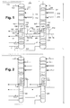
- FIG. 3 which is explained below, shows an example of a four-stranded embodiment.
- the four columns in the form of two double columns are arranged side by side, as described in claim 2 in detail.
- the two double columns can be prefabricated in the workshop and then transported to the site, the critical transport dimensions, for example, a maximum of 4.8 m diameter are met and still a high capacity of the distillation column system strand is achieved.
- the two double columns are installed in an insulation, preferably in a common cold box.
- the first main capacitor is arranged in the bottom region of the first low-pressure column.
- the main condenser is below the mass transfer elements of the first low-pressure column in the same container as this.
- the main capacitor is used for the operation of all four columns. This arrangement can be applied to both variants of the invention.
- the main condenser is arranged in a separate container from the first low-pressure column, which is located, for example, between the first low-pressure column and the first high-pressure column or adjacent to these two columns.
- the first and the second high-pressure column can be supplied separately with air via two strands.
- both are supplied via a common air line, which delivers a total compressed air flow, which is branched into at least two compressed air streams, wherein the first compressed air sub-stream is introduced into the first high-pressure column and the second compressed air sub-stream in the second high-pressure column.
- the air separation train formed by the four columns of the distillation column system then has only a single strand for air compression, purification and cooling.
- the second low-pressure column, the first low-pressure column, the main condenser, the first high-pressure column and the second high-pressure column are arranged in a common coldbox.
- a single main condenser can supply all four columns with reflux liquid. In this way, a reduction in the expenditure on equipment and a particularly high flexibility in the installation of the individual column, which can be used for a space-saving arrangement of the columns.
- the columns are connected in pairs in parallel, resulting in a particularly high capacity with limited column diameter.
- a separate second main capacitor for the second high pressure column and the second low pressure column is used, which is arranged for example in the bottom of the second low pressure column.
- the evaporation space of a common first main capacitor must also be charged with liquid. This happens in the invention for example, in that both a first liquid oxygen stream from the first low-pressure column and a second liquid oxygen stream from the second low-pressure column are introduced into the evaporation space of the main condenser.
- the invention also relates to a device according to claim 6.
- the device according to the invention can be supplemented by device features which correspond to the features of the dependent method claims.
- each of the strands can be constructed, for example, in parallel in four or five times identical copy and then forms a multi-stranded system according to the invention.
- the main air compressors, cleaning devices and main heat exchangers, not shown, are also four- or five-stranded in these embodiments.
- the distillation column system of the embodiment of the FIG. 1 has a first high-pressure column 101, a second high-pressure column 201, a first low-pressure column 102, a second low-pressure column 202, a first main capacitor 103 and a second main capacitor 203.
- Both main capacitors 103, 203 are formed in the example by a respective six-stage or two three-stage cascade evaporator.
- the columns are arranged in the form of two double columns.
- Each double column can be controlled substantially independently.
- the pressure in the low-pressure columns for example, can be set and controlled separately. Through this decoupling, the overall control effort is made easier and any manufacturing tolerances in both double columns can be better compensated.
- a total compressed air flow 1 is brought up. This was, as usual in the air separation, compressed in a main air compressor, cleaned in a cleaning device and cooled in a main heat exchanger to about dew point. (These steps are not shown in the drawing.)
- the total compressed air flow 1 is branched into a first compressed air sub-stream 100 and a second compressed air sub-stream 200.
- the first compressed air sub-stream 100 is introduced into the first high-pressure column 101, the second compressed air sub-stream 200 into the second high-pressure column 201.
- the main condenser 103 has a uniform liquefaction space and a uniform evaporation space, ie these spaces are not subdivided into one or more liquefaction subspaces and / or evaporation subspaces, as in other exemplary embodiments of the invention.
- a first nitrogen gas stream 104, 114 from the first high-pressure column 101 is introduced into the liquefaction space of the first main condenser 103.
- liquid nitrogen 115 is generated, which is passed to at least a first part as a first liquid nitrogen stream 105 to the first high-pressure column 101.
- a second nitrogen gas stream 204, 214 from the second high-pressure column 201 is introduced into the liquefaction space of the second main condenser 203.
- liquid nitrogen 215 is generated, which is passed to at least a first part as a second liquid nitrogen flow 205 to the second high-pressure column 201.
- a first liquid oxygen stream 106 from the first low-pressure column 102 flows from the lower end of the lowermost mass transfer layer 107 of the first low-pressure column 102 and is thereby introduced into the evaporation space of the first main capacitor 103.
- gaseous oxygen is formed in the evaporation space of the first main capacitor 103. It is introduced at least to a first part as the first oxygen gas stream 108 in the first low pressure column 102 by flowing from below into the bottom mass transfer layer 107 of the first low-pressure column 102; if necessary, a second part can be obtained directly as a gaseous oxygen product and heated in the main heat exchanger.
- a second liquid oxygen stream 206 from the second low-pressure column 202 flows from the lower end of the lowermost mass transfer layer 107 of the second low-pressure column 202 and is thereby introduced into the evaporation space of the second main condenser 203.
- gaseous oxygen is formed in the evaporation space of the second main capacitor 203. It is introduced at least to a first part as a second oxygen gas stream 208 in the second low-pressure column 202 by flowing from below into the bottom mass transfer layer 207 of the second low-pressure column 202; if necessary, a second part can be obtained directly as a gaseous oxygen product and heated in the main heat exchanger.
- the reflux liquids 109, 209 for the two low-pressure columns 102, 202 are each formed by a nitrogen-enriched liquid 20, which at both High pressure columns 101, 201 is withdrawn from an intermediate point or directly from the head. From the top of both low-pressure columns 102, 202, impure nitrogen 110, 210 is withdrawn and passed as residual gas through a subcooling countercurrent to the main heat exchanger (both not shown).
- each oxygen-enriched bottoms liquid stream cooled in the subcooling countercurrent 23 and introduced into the evaporation space of the top condenser or top condensers at least one crude argon column.
- the bottoms can either be run separately or mixed before the supercooling countercurrent and then split.
- Via the lines 111, 211, low-pressure columns 102, 202 are fed with liquid air at an intermediate point. This liquid air originates from the main heat exchanger, in which liquid pressurized oxygen 41 evaporates from the low pressure columns or (if the oxygen pressure is supercritical) is pseudo-vaporized.
- liquid oxygen 141, 241 is withdrawn from the evaporation spaces of the main condensers 103, 203, combined and fed via line 14 to an internal compression, not shown.
- the liquid oxygen is pumped to a high product pressure, vaporized or pseudo-evaporated under this high product pressure, warmed to about ambient temperature and finally stripped off as gaseous pressure oxygen product.
- pressurized nitrogen is withdrawn directly from the head of the high-pressure columns 101, 201 (lines 104, 142 and 204), passed together via line 42 to the main heat exchanger, warmed there and finally recovered as a gaseous pressurized nitrogen product.
- a part 143, 243 of the liquid nitrogen produced in the main condensers 103, 104 can each be supplied to an internal compression and recovered as a high-pressure gaseous nitrogen product.
- argon is to be produced as a product, via the line pairs 113, 114, 213, 214 a common classical argon recovery or a separate first and a second argon recovery may be connected, wherein the line pairs 113, 213 are connected to the lower portion of a crude argon column or each one of two parallel Rohargonklalen.
- the internal structure and mode of operation of such a classic argon recovery are, for example, in DE 2325422 A .
- EP 942246 A2 EP 1103772 A1 .
- a crude argon column can be connected in a similar manner, which then serves only for the discharge of argon.
- the crude argon column (s) and optionally the pure argon column (s) can be housed in separate cold boxes or in a common cold box with one or both double columns.
- the mass transfer elements in the two low-pressure columns 102, 202 are formed exclusively by ordered packing.
- the oxygen sections of the two low-pressure columns 102, 202 (area below the lines 113/213 are provided with an ordered packing having a specific surface area of 700 m 2 / m 3 or alternatively 1200 m 2 / m 3 , in the remaining sections, the packing has a specific surface area of 500 m 2 / m 3.
- the two low-pressure columns 10, 202 may have a nitrogen section above the mass transfer sections shown in the drawing, which is then packed with a specific surface area of 500 m 2 / m 3 or alternatively of 1200 m 2 / m 3 were charged. Notwithstanding this, it is possible to combine a structured packing of different specific surface within each of said sections.
- the mass transfer elements are formed exclusively by ordered packing with a specific surface area of 1200 m 2 / m 3 .
- some of the mass transfer elements in one or both high pressure columns 101, 201 could be formed by conventional distillation trays, for example through sieve trays.
- FIG. 2 is different from this FIG. 1 in that the mass transfer elements of the high-pressure columns 101, 201 are formed exclusively by sieve trays.
- the main condensers are six-stage cascade evaporators educated. Alternatively, it is also possible to use two three-stage cascade evaporators.
- FIG. 1 and 2 can be modified in that instead of two three-stage main capacitors 103, 203 and respectively a six-stage main capacitor 103, 203, a common main capacitor is used, which is formed for example as a two-block existing six-stage cascade evaporator. This is then preferably not placed in the container of one of the low-pressure columns 102, 202, but outside in a separate container.
- FIG. 3 is a multi-stranded plant by two or more distillation column systems according to one of Figures 1 or 2 educated.
- Each distillation column system is enclosed by its own Coldbox 301 and forms a strand of a distillation column system.
- all four air separation strands are constructed identically; alternatively, individual or all strands could be designed differently.
- Each string has an atmospheric air inlet filter 302, a main air compressor 303, an air pre-cooler 304, an air purifier 305 (typically formed by a pair of molecular sieve adsorbers), a Booster Air Compressor 306 with aftercooler 307, and an air cooler 306 Main heat exchanger 308 in its own coldbox 309; These devices are each independent of the other strands.
- the post-compressed air in the reboiler 306 is liquefied (or pseudo-liquefied, if its pressure is supercritical) via line 311 to the distillation column system in the cold box 300 where it flows into the streams 111 and 112 of FIG FIG. 1 branched.
- the further flow 1 emerging from the main heat exchanger 308 and the fluids 41, 42, 32 flowing to the warm end of the main heat exchanger 308 are as in FIG. 1 numbered.
- the liquid oxygen 32 is vaporized or pseudo-evaporated in the main heat exchanger under high pressure (internal compression). All return streams are warmed in the main heat exchanger to about ambient temperature and withdrawn via the product lines P.
- Both the warm part (air compression, pre-cooling and air purification) and / or the main heat exchanger may have a different number of strands than have the distillation column system.
- one distillation column system strand could be supplied by two main air compressor strands or two distillation column system strands from four main air compressor strands.
- the concept of the invention can also be applied to a process without air recompression 306/307 (for example, with the total air compressed to more than 5 bar above the highest of the operating pressures of the two high pressure columns) or to processes with other elements such as a nitrogen cycle.
- the refrigeration is in FIG. 3 not shown. Any known type of turbine circuit can be chosen, with one, two or more turbines.
- the distillation column system is in FIG. 3 deviating from the Figures 1 and 2 shown without argon recovery; but it can - as in the Figures 1 and 2 - Have an argon recovery, or even a column for the discharge of argon to improve the rectification.
- the number of distillation column system strands can be reduced by the invention, for example from six to five or from five to four.
Landscapes
- Engineering & Computer Science (AREA)
- Physics & Mathematics (AREA)
- Mechanical Engineering (AREA)
- Thermal Sciences (AREA)
- General Engineering & Computer Science (AREA)
- Health & Medical Sciences (AREA)
- Emergency Medicine (AREA)
- Separation By Low-Temperature Treatments (AREA)
Abstract
Das Verfahren und die Anlage dienen zur Tieftemperaturzerlegung von Luft mit einer mehrsträngigen Anlage mit mindestens zwei Luftzerlegungsstränge, wobei beide jeder der zwei Luftzerlegungsstränge eine Coldbox aufweist, die ein Destillationssäulen-System enthält, das eine erste Hochdrucksäule (101), eine erste Niederdrucksäule (102) und einen ersten Hauptkondensator (103) aufweist, der als Kondensator-Verdampfer ausgebildet ist und einen Verdampfungsraum und einen Verflüssigungsraum aufweist. Ein erster Stickstoffgasstrom (104, 114) aus der ersten Hochdrucksäule (101) wird in den Verflüssigungsraum des ersten Hauptkondensators (103) eingeleitet. Ein erster Flüssigstickstoffstrom (105) aus dem Verflüssigungsraum des ersten Hauptkondensators (103) wird in die erste Hochdrucksäule (101) eingeleitet. Ein erster Sauerstoffgasstrom (108) aus dem Verdampfungsraum des Hauptkondensators (103) wird in die erste Niederdrucksäule (102) eingeleitet. Das Destillationssäulen-System beider Luftzerlegungsstränge weist außerdem eine zweite Hochdrucksäule (201) und eine zweite Niederdrucksäule auf. Die erste Hochdrucksäule (101) und die zweite Hochdrucksäule (201) der Destillationssäulen-Systeme jeder der beiden Luftzerlegungsstränge weisen die gleiche Baugröße auf. Die erste Niederdrucksäule und die zweite Niederdrucksäule der Destillationssäulen-Systeme jeder der beiden Luftzerlegungsstränge weisen die gleiche Baugröße auf. Die erste und die zweite Niederdrucksäule (102, 202) der Destillationssäulen-Systeme jeder der beiden Luftzerlegungsstränge enthalten Stoffaustauschelemente, die in mindestens einem Teilbereich der jeweiligen Niederdrucksäule (102, 202) durch eine geordnete Packung gebildet werden, die aus gefalteten Metallblechen gefertigt ist, wobei die geordnete Packung eine spezifische Oberfläche von mehr als 1000 m 2 /m 3 , insbesondere von 1200 m 2 /m 3 oder mehr, aufweist.
Description
- Die Erfindung betrifft ein Verfahren zur Tieftemperaturzerlegung von Luft gemäß dem Oberbegriff des Patentanspruchs 1.
- Die Grundlagen der Tieftemperaturzerlegung von Luft im Allgemeinen sowie der Aufbau von Zwei-Säulen-Anlagen im Speziellen sind in der Monografie "Tieftemperaturtechnik" von Hausen/Linde (2. Auflage, 1985) und in einem Aufsatz von Latimer in Chemical Engineering Progress (Vol. 63, No.2, 1967, Seite 35) beschrieben. Die Wärmeaustauschbeziehung zwischen Hochdrucksäule und Niederdrucksäule einer Doppelsäule wird im Regelfall durch einen Hauptkondensator realisiert, in dem Kopfgas der Hochdrucksäule gegen verdampfende Sumpfflüssigkeit der Niederdrucksäule verflüssigt wird.
- Das Destillationssäulen-System der Erfindung kann ist grundsätzlich als klassisches Zwei-Säulen-System mit Hochdrucksäule und Niederdrucksäule ausgebildet. Es kann zusätzlich zu den Trennsäulen zur Stickstoff-Sauerstoff-Trennung weitere Vorrichtungen zur Gewinnung anderer Luftkomponenten, insbesondere von Edelgasen aufweisen, beispielsweise eine Argongewinnung.
- Der Hauptkondensator ist bei der Erfindung als Kondensator-Verdampfer ausgebildet. Als "Kondensator-Verdampfer" wird ein Wärmetauscher bezeichnet, in dem ein erster, kondensierender Fluidstrom in indirekten Wärmeaustausch mit einem zweiten, verdampfenden Fluidstrom tritt. Jeder Kondensator-Verdampfer weist einen Verflüssigungsraum und einen Verdampfungsraum auf, die aus Verflüssigungspassagen beziehungsweise Verdampfungspassagen bestehen. In dem Verflüssigungsraum wird die Kondensation (Verflüssigung) eines ersten Fluidstroms durchgeführt, in dem Verdampfungsraum die Verdampfung eines zweiten Fluidstroms. Verdampfungs- und Verflüssigungsraum werden durch Gruppen von Passagen gebildet, die untereinander in Wärmeaustauschbeziehung stehen.
- Dabei kann der Hauptkondensator als Badverdampfer, insbesondere als Kaskadenverdampfer (beispielsweise wie in
EP 1287302 B1 =US 6748763 B2 beschrieben), oder aber als Fallfilmverdampfer ausgebildet sein. Er kann durch einen einzigen Wärmetauscherblock gebildet werden oder auch durch mehrere Wärmetauscherblöcke, die in einem gemeinsamen Druckbehälter angeordnet sind. - Das Destillationssäulen-System eine Luftzerlegungsanlage ist in einer oder mehreren Coldboxen angeordnet. Unter einer "Coldbox" wird hier eine isolierende Umhüllung verstanden, die einen wärmeisolierten Innenraum vollständig mit Außenwänden umfasst; in dem Innenraum sind zu isolierenden Anlagenteile angeordnet, zum Beispiel ein oder mehrere Trennsäulen und/oder Wärmetauscher. Die isolierende Wirkung kann durch entsprechende Ausgestaltung der Außenwände und/oder durch die Füllung des Zwischenraums zwischen Anlagenteilen und Außenwänden mit einem Isoliermaterial bewirkt werden. Bei der letzteren Variante wird vorzugsweise ein pulverförmiges Material wie zum Beispiel Perlite verwendet. Sowohl das Destilliersäulen-System zur Stickstoff-Sauerstoff-Trennung einer Tieftemperatur-Luftzerlegungsanlage als auch der Hauptwärmetauscher und weitere kalte Anlagenteile müssen von einer oder mehreren Coldboxen umschlossen sein. Die Außenmaße der Coldbox bestimmen üblicherweise die Transportmaße des Pakets bei vorgefertigten Anlagen.
- Die Erfindung bezieht sich auf eine mehrsträngige Anlage, die mindestens bezüglich des Destillationssäulen-Systems zwei grundsätzlich voneinander unabhängige Stränge (trains) aufweist. Die zwei oder mehr Destillationssäulen-System-Stränge sind regelmäßig in Ihrem Inneren gleich aufgebaut; ein oder mehrere Stränge können aber auch verschieden von den anderen ausgestaltet sein. Die Verfahrensschritte stromaufwärts und stromabwärts des Destillationssäulen-Systems können einsträngig oder ebenfalls mehrsträngig ausgebildet sein, wobei die Zahl der Stränge in den verschiedenen seriellen Schritten gleich oder unterschiedlich sein kann. In einem konkreten Beispiel ist ein dreisträngig ausgebildeter Hauptluftverdichter mit einer einsträngigen Luftvorkühlung und -reinigung verbunden und die gereinigte Luft wird in einen dreisträngigen kalten Teil eingeleitet, wobei jeder der kalten Stränge einen Hauptwärmetauscher und ein Destillationssäulen-System enthält.
- Mehrsträngige Verfahren der eingangs genannten Art und entsprechende Vorrichtungen sind aus
WO 2013093305 A1 ,WO 2013104840 A1 ,WO 2009024672 A2 undEP 1666823 A1 =US 7516626 B2 bekannt. - Im Falle einer Transportbegrenzung (üblicherweise 4,8 m im Säulendurchmesser) wird die pro Anlage (Strang) gewonnene Produktmenge stark limitiert. Daher werden oftmals viele Anlagen-Stränge (trains) benötigt, um die geforderte Produktmenge beispielsweise an Sauerstoff an Kunden zu liefern. Die Begrenzung des Säulendurchmessers führt außerdem dazu, dass die Säulen mehrsträngiger Anlagen in der Coldbox mit Packungen mit sehr niedriger spezifischen Oberfläche (zum Beispiel 350 m2/m2) ausgerüstet werden; Entsprechendes gilt für einsträngige Anlagen sehr großer Kapazität. Dies ist insofern günstig, dass bei beschränktem Säulendurchmesser eine besonders hohe Kapazität pro Säule erreicht wird. Die Säulen werden dabei besonders hoch und es besteht auch die Notwendigkeit für Einsatz kryogener Transferpumpen (entweder eine Flüssigstickstoff-Pumpe für eine Anordnung der Säulen übereinander oder eine Flüssigsauerstoff-Transferpumpe für nebeneinander stehende Säulen). Neben einer Erhöhung der Gesamtkosten werden dadurch auch die Komplexität und der Energiebedarf des Systems negativ beeinflusst.
- Der Erfindung liegt die Aufgabe zugrunde, ein derartiges Verfahren und eine entsprechende Vorrichtung anzugeben, die hohe Kapazität, relativ niedrige Investitionskosten und einen vergleichsweise geringem Flächenbedarf bei günstigem Energiebedarf aufweisen.
- Diese Aufgabe wird durch die kennzeichnenden Merkmale des Patentanspruchs 1 gelöst.
- Entgegengesetzt zu der bisherigen Praxis bei Beschränkungen des Kolonnendurchmessers wird bei der Erfindung eine geordnete Packung besonders großer Dichte in den Niederdrucksäulen eingesetzt. Dabei kann ein Teil des Stoffaustauschbereichs jeder der beiden Niederdrucksäulen mit einer besonders dichten Packung gefüllt sein (und der Rest beispielsweise durch Packung niedrigerer Dichte oder auch durch eine Kombination aus Packung und konventionellen Rektifizierböden), oder alle Stoffaustauschelemente werden durch die besonders dichte Packung gebildet. In den Hochdrucksäulen werden entweder auch eine geordnete Packung, vorzugsweise mit mehr als 1000 m2/m3, oder Siebböden oder eine Kombination dieser beiden Typen von Stoffaustauschelementen eingesetzt. Aufgrund der erfindungsgemäßen paarweisen Parallelschaltung von Säulen kann trotz eines beschränkten Kolonnendurchmessers eine besonders hohe Produktkapazität (pro Strang) erzielt werden; die dafür benötigte Grundfläche und die Coldboxhöhe bleiben dabei relativ klein, nämlich vergleichbar einem Destillationssäulen-System mit einer einzelnen Doppelsäule, die Packungen mit sehr niedriger spezifischer Oberfläche (zum Beispiel 350 oder 500 m2/m2) gefüllt ist.
- Die Hochdrucksäulen und die Niederdrucksäulen eines Strangs weisen gemäß der Erfindung paarweise die "gleiche Baugröße" auf. Darunter wird hier verstanden, dass die entsprechenden Kolonnenhöhen und -durchmesser nicht mehr als 10 %, insbesondere nicht mehr als 5 % voneinander abweichen. Der Vergleich bezieht sich paarweise auf die einander entsprechenden Abschnitte der erste und der zweiten Hochdrucksäulen beziehungsweise der ersten und der zweiten Niederdrucksäulen
- Der Einsatz einer besonders dichten Packung scheint zunächst kontraproduktiv für eine besonders hohe Kapazität zu sein, weil dadurch bei begrenztem Kolonnendurchmesser die Kapazität der entsprechenden Säule sinkt. Im Rahmen der Erfindung hat sich jedoch überraschenderweise herausgestellt, dass eine solche Ausgestaltung dann günstiger ist, wenn ein Destillationssäulen-System-Strang durch zwei parallele Zwei-Säulen-Systeme gebildet wird, insbesondere dann, wenn für beide ein gemeinsamer Hauptkondensator genutzt wird. Ein einzelner Strang wird dadurch natürlich apparativ aufwändiger; es kann aber eine überraschend deutlich erhöhte Kapazität erreicht werden im Vergleich zu einem klassischen Destillationssäulen-System-Strang.
- Aufgrund der erfindungsgemäßen paarweisen Parallelschaltung von Säulen innerhalb eines Strangs kann trotz eines beschränkten Kolonnendurchmessers eine besonders hohe Produktkapazität (pro Strang) erzielt werden; die dafür benötigte Grundfläche sowie die Höhe der Coldbox bleiben dabei relativ klein. Beispielsweise kann im Rahmen der Erfindung die Kapazität für die Sauerstofferzeugung um 20 bis 30 % gegenüber einer klassischen Ausgestaltung erhöht werden.
- Aus
US 6128921 ist es zwar bekannt zwei parallel geschaltete Doppelsäulen nebeneinander in einer gemeinsamen Coldbox zu betreiben; allerdings bezieht sich diese Schrift nur auf eine einsträngige Anlage und zielt darauf, die beiden Doppelsäulen verschieden auszubilden. Der Fachmann würde diese Veröffentlichung nicht konsultieren, wenn er auf der Suche nach einer Verbesserung mehrsträngiger Systeme ist; er entnimmt ihr jedenfalls keine Anregung, wie ein mehrsträngiges System der eingangs genannten Art im Sinne der oben beschriebenen Aufgabe verändert werden könnte. - Die Vorteile des erfindungsgemäßen Verfahrens kommen insbesondere bei besonders großen Anlagen zum Tragen, die mehrsträngig ausgebildet sind, wobei mindestens zwei Stränge oder alle Stränge der Gesamtanlage gemäß der Erfindung ausgebildet sind. Durch die Kapazitätserhöhung pro Strang kann beispielsweise mit einer viersträngigen Anlage gemäß der Erfindung eine Gesamtkapazität erreicht werden, die einer konventionellen fünfsträngigen Anlage entspricht; bei einer Anlage, die konventionell mit sechs Strängen ausgestaltet werden müsste, reichen beispielsweise fünf erfindungsgemäße Stränge.
- Die Erfindung wird durch eine zwei- oder mehrsträngige Anlage realisiert, wobei mindestens zwei Luftzerlegungsstränge durch Destillationssäulen-Systeme mit den je vier Säulen gebildet werden. Jedes Destillationssäulen-System ist von einer eigenen Coldbox oder von mehreren Coldboxen umschlossen und bildet einen Strang.
Figur 3 , die weiter unten erläutert ist, zeigt ein Beispiel für eine viersträngige Ausgestaltung. - Bei der Erfindung sind die vier Säulen in Form zweier Doppelsäulen nebeneinander angeordnet, wie es im Patentanspruch 2 im Einzelnen beschrieben ist. Die beiden Doppelsäulen können in der Werkstatt vorgefertigt und anschließend auf die Baustelle transportiert werden, wobei die kritischen Transportmaße, zum Beispiel maximal 4,8 m Durchmesser eingehalten werden und trotzdem eine hohe Kapazität des Destillationssäulen-System-Strangs erreicht wird. Auf der Baustelle werden die beiden Doppelsäulen in eine Isolierung eingebaut, vorzugsweise in eine gemeinsame Coldbox.
- In einer bevorzugten Ausgestaltung der Erfindung ist der erste Hauptkondensator im Sumpfbereich der ersten Niederdrucksäule angeordnet. Damit ist gemeint, dass sich der Hauptkondensator unterhalb der Stoffaustauschelemente der ersten Niederdrucksäule im selben Behälter wie diese befindet. Der Hauptkondensator wird dabei für den Betrieb aller vier Säulen genutzt. Diese Anordnung kann auf beide Varianten der Erfindung angewendet werden.
- Alternativ ist der Hauptkondensator in einem von der ersten Niederdrucksäule getrennten Behälter angeordnet, der sich beispielsweise zwischen erste Niederdrucksäule und erste Hochdrucksäule oder neben diesen beiden Säulen befindet.
- Grundsätzlich können die erste und die zweite Hochdrucksäule über zwei Stränge separat mit Luft versorgt werden. Vorzugsweise werden beide jedoch über eine gemeinsame Luftleitung versorgt, die einen Gesamtdruckluftstrom liefert, der in mindestens zwei Druckluftteilströme verzweigt wird, wobei der erste Druckluftteilstrom in die erste Hochdrucksäule und der zweite Druckluftteilstrom in die zweite Hochdrucksäule eingeleitet wird. Der Luftzerlegungsstrang, der durch die vier Säulen des Destillationssäulen-Systems gebildet wird, weist dann nur einen einzigen Strang für die Luftverdichtung, -reinigung und -abkühlung auf.
- Es ist außerdem günstig, wenn die zweite Niederdrucksäule, die erste Niederdrucksäule, der Hauptkondensator, die erste Hochdrucksäule und die zweite Hochdrucksäule in einer gemeinsamen Coldbox angeordnet sind.
- Bei der Erfindung kann ein einziger Hauptkondensator alle vier Säulen mit Rücklaufflüssigkeit versorgen. Auf diese Weise ergeben sich eine Verminderung des apparativen Aufwands und eine besonders hohe Flexibilität bei der Aufstellung der einzelnen Säule, die für eine Platz sparende Anordnung der Säulen genutzt werden kann. Die Säulen sind paarweise parallelgeschaltet, sodass sich eine besonders hohe Kapazität bei begrenztem Säulendurchmesser ergibt. Alternativ wird bei der Erfindung ein separater zweiter Hauptkondensator für die zweite Hochdrucksäule und die zweite Niederdrucksäule eingesetzt, der zum Beispiel im Sumpf der zweiten Niederdrucksäule angeordnet ist.
- Natürlich muss der Verdampfungsraum eines gemeinsamen ersten Hauptkondensators auch mit Flüssigkeit beaufschlagt werden. Dies geschieht bei der Erfindung beispielsweise dadurch, dass sowohl ein erster Flüssigsauerstoffstrom aus der ersten Niederdrucksäule als auch ein zweiter Flüssigsauerstoffstrom aus der zweiten Niederdrucksäule in den Verdampfungsraum des Hauptkondensators eingeleitet werden.
- Wenn der Hauptkondensator aus mehreren parallelen Blöcken besteht, gibt es verschiedene Möglichkeiten der Verbindung zwischen den Ein- und Austritten der Verdampfungs- und Verflüssigungsteilräume der Blöcke, die untereinander grundsätzlich beliebig kombiniert werden können:
- Eintritt des Verdampfungsteilraums eines Blocks verbunden mit nur einer der beiden Niederdrucksäulen oder mit beiden Niederdrucksäulen
- Austritt des Verdampfungsteilraums eines Blocks verbunden mit nur einer der beiden Niederdrucksäuleen oder mit beiden Niederdrucksäulen
- Eintritt des Verflüssigungsteilraums eines Blocks verbunden mit nur einer der beiden Hochdrucksäulen oder mit beiden Hochdrucksäulen
- Austritt des Verflüssigungsteilraums eines Blocks verbunden mit nur einer der beiden Hochdrucksäulen oder mit beiden Hochdrucksäulen
- Die Erfindung betrifft außerdem eine Vorrichtung gemäß Patentanspruch 6. Die erfindungsgemäße Vorrichtung kann durch Vorrichtungsmerkmale ergänzt werden, die den Merkmalen der abhängigen Verfahrensansprüche entsprechen.
- Die Erfindung sowie weitere Einzelheiten der Erfindung werden im Folgenden anhand zweier in der Zeichnung schematisch dargestellten Ausführungsbeispiele näher erläutert. In den Zeichnungen sind nur die wichtigsten Elemente dargestellt, insbesondere solche, mit denen sich das System der Erfindung von üblichen Luftzerlegungssystemen unterscheidet. Hierbei zeigen:
- Figur 1
- ein erstes Ausführungsbeispiel für ein Destillationssäulen-System gemäß er Erfindung,
- Figur 2
- ein zweites Ausführungbeispiel für ein Destillationssäulen-System der Erfindung und
- Figur 3
- die Darstellung eines mehrsträngigen Systems gemäß der Erfindung.
- In den
Figuren 1 und 2 ist jeweils nur ein Destillationssäulen-System eines Stranges dargestellt mit jeweils vier Säulen. Jeder der Stränge kann beispielweise in vier- oder fünffacher identischer Ausfertigung parallel aufgebaut werden und bildet dann ein erfindungsgemäßes mehrsträngiges System. Die nicht dargestellten Hauptluftverdichter, Reinigungseinrichtungen und Hauptwärmetauscher sind bei diesen Ausführungsbeispielen ebenfalls vier- beziehungsweise fünfsträngig ausgebildet.. - Das Destillationssäulen-System des Ausführungsbeispiels der
Figur 1 weist eine erste Hochdrucksäule 101, eine zweite Hochdrucksäule 201, eine erste Niederdrucksäule 102, eine zweite Niederdrucksäule 202, eine ersten Hauptkondensator 103 und einen zweiten Hauptkondensator 203 auf. Beide Hauptkondensatoren 103, 203 werden in dem Beispiel durch je einen sechsstufigen oder je zwei dreistufige Kaskadenverdampfer gebildet. Die Säulen sind in Form zweier Doppelsäulen angeordnet. - Jede Doppelsäule kann im Wesentlichen unabhängig geregelt werden. Der Druck in den Niederdrucksäulen kann beispielsweise separat eingestellt und geregelt werden. Durch diese Entkopplung wird auch der Gesamt-Regelungsaufwand leichter gestaltet und eventuelle Fertigungstoleranzen bei beiden Doppelsäulen können besser ausgeglichen werden.
- Über eine gemeinsame Luftleitung wird ein Gesamtdruckluftstrom 1 herangeführt. Dieser wurde, wie in der Luftzerlegung üblich, in einem Hauptluftverdichter verdichtet, in einer Reinigungseinrichtung gereinigt und in einem Hauptwärmetauscher auf etwa Taupunkt abgekühlt. (Diese Schritte sind in der Zeichnung nicht dargestellt.) Der Gesamtdruckluftstrom 1 wird in einen ersten Druckluftteilstrom 100 und einen zweiten Druckluftteilstrom 200 verzweigt. Der erste Druckluftteilstrom 100 wird in die erste Hochdrucksäule 101, der zweite Druckluftteilstrom 200 in die zweite Hochdrucksäule 201 eingeleitet.
- Der Hauptkondensator 103 weist in dem Ausführungsbeispiel einen einheitlichen Verflüssigungsraum und einen einheitlichen Verdampfungsraum auf, das heißt diese Räume sind nicht - wie bei anderen Ausführungsbeispielen der Erfindung - in einen oder mehrere Verflüssigungsteilräumen und/oder Verdampfungsteilräume unterteilt. Ein erster Stickstoffgasstrom 104, 114 aus der ersten Hochdrucksäule 101 wird in den Verflüssigungsraum des ersten Hauptkondensators 103 eingeleitet. In dem Verflüssigungsraum des ersten Hauptkondensators 103 wird Flüssigstickstoff 115 erzeugt, der mindestens zu einem ersten Teil als ein erster Flüssigstickstoffstrom 105 zur ersten Hochdrucksäule 101 geleitet wird.
- Ein zweiter Stickstoffgasstrom 204, 214 aus der zweiten Hochdrucksäule 201 wird in den Verflüssigungsraum des zweiten Hauptkondensators 203 eingeleitet. In dem Verflüssigungsraum des zweiten Hauptkondensators 203 wird Flüssigstickstoff 215 erzeugt, der mindestens zu einem ersten Teil als ein zweiter Flüssigstickstoffstrom 205 zur zweiten Hochdrucksäule 201 geleitet wird..
- Ein erster Flüssigsauerstoffstrom 106 aus der ersten Niederdrucksäule 102 fließt vom unteren Ende der der untersten Stoffaustauschschicht 107 der ersten Niederdrucksäule 102 ab und wird dadurch in den Verdampfungsraum des ersten Hauptkondensators 103 eingeleitet. In dem Verdampfungsraum des ersten Hauptkondensators 103 wird gasförmiger Sauerstoff gebildet. Er wird mindestens zu einem ersten Teil als erster Sauerstoffgasstrom 108 in die erste Niederdrucksäule 102 eingeleitet, indem er von unten in die unterste Stoffaustauschschicht 107 der ersten Niederdrucksäule 102 einströmt; ein zweiter Teil kann bei Bedarf direkt als gasförmiges Sauerstoffprodukt gewonnen und im Hauptwärmetauscher angewärmt werden.
- Ein zweiter Flüssigsauerstoffstrom 206 aus der zweiten Niederdrucksäule 202 fließt vom unteren Ende der der untersten Stoffaustauschschicht 107 der zweiten Niederdrucksäule 202 ab und wird dadurch in den Verdampfungsraum des zweiten Hauptkondensators 203 eingeleitet. In dem Verdampfungsraum des zweiten Hauptkondensators 203 wird gasförmiger Sauerstoff gebildet. Er wird mindestens zu einem ersten Teil als zweiter Sauerstoffgasstrom 208 in die zweite Niederdrucksäule 202 eingeleitet, indem er von unten in die unterste Stoffaustauschschicht 207 der zweiten Niederdrucksäule 202 einströmt; ein zweiter Teil kann bei Bedarf direkt als gasförniges Sauerstoffprodukt gewonnen und im Hauptwärmetauscher angewärmt werden.
- Die Rücklaufflüssigkeiten 109, 209 für die beiden Niederdrucksäulen 102, 202 werden jeweils durch eine stickstoffangereicherte Flüssigkeit 20 gebildet, die an beiden Hochdrucksäulen 101, 201 von einer Zwischenstelle oder direkt vom Kopf abgezogen wird. Vom Kopf beider Niederdrucksäulen 102, 202 wird unreiner Stickstoff 110, 210 abgezogen und als Restgas durch einen Unterkühlungs-Gegenströmer zum Hauptwärmetauscher (beide nicht dargestellt) geführt.
- Ebenfalls nicht dargestellt ist, wie von beiden Hochdrucksäulen 101, 201 je ein sauerstoffangereicherter Sumpfflüssigkeitstrom abgezogen, im Unterkühlungs-Gegenströmer 23 abgekühlt und in den Verdampfungsraum des Kopfkondensators oder der Kopfkondensatoren mindestens einer Rohargonsäule eingeleitet wird. Die Sumpfflüssigkeiten können dabei entweder separat geführt oder vor dem Unterkühlungs-Gegenströmer vermischt und anschließend aufgeteilt werden. Über die Leitungen 111, 211 wird den Niederdrucksäulen 102, 202 Flüssigluft an einer Zwischenstelle zugespeist. Diese Flüssigluft stammt aus dem Hauptwärmetauscher, in dem flüssig auf Druck gebrachter Sauerstoff 41 aus den Niederdrucksäulen verdampft oder (falls der Sauerstoffdruck überkritisch ist) pseudo-verdampft wird.
- Als Hauptprodukt des Destillationssäulen-Systems wird flüssiger Sauerstoff 141, 241 von den Verdampfungsräumen der Hauptkondensatoren 103, 203 abgezogen, zusammengeführt und über Leitung 14 einer nicht dargestellten Innenverdichtung zugeführt. Dabei wird der flüssige Sauerstoff auf einen hohen Produktdruck gepumpt, unter diesem hohen Produktdruck verdampft oder pseudo-verdampft, auf etwa Umgebungstemperatur angewärmt und schließlich als gasförmiges Drucksauerstoffprodukt abgezogen.
- Als weiteres Produkt des Destillationssäulen-Systems wird Druckstickstoff direkt vom Kopf der Hochdrucksäulen 101, 201 abgezogen (Leitungen 104, 142 und 204), gemeinsam über Leitung 42 zum Hauptwärmetauscher geführt, dort angewärmt und schließlich als gasförmiges Druckstickstoffprodukt gewonnen. Zusätzlich kann jeweils ein Teil 143, 243 des in den Hauptkondensatoren 103, 104 erzeugten Flüssigstickstoffs einer Innenverdichtung zugeführt und als gasförmiges Hochdruck-Stickstoffprodukt gewonnen werden.
- Falls Argon als Produkt erzeugt werden soll, können über die Leitungspaare 113, 114, 213, 214 eine gemeinsame klassische Argongewinnung oder je eine separate erste und eine zweite Argongewinnung angeschlossen sein, wobei die Leitungspaare 113, 213 mit dem unteren Bereich einer Rohargonsäule oder jeweils einer von zwei parallelen Rohargonsäulen verbunden sind. Der innere Aufbau und die Funktionsweise einer solchen klassischen Argongewinnung sind beispielweise in
DE 2325422 A ,EP 171711 A2 EP 377117 B2 US 5019145 ),DE 4030749 A1 ,EP 628777 B1 US 5426946 ),EP 669508 A1 US 5592833 ),EP 669509 B1 US 5590544 ),EP 942246 A2 EP 1103772 A1 ,DE 19609490 (=US 5669237 ), Figur 8,EP 1243882 A1 (=US 2002178747 A1 ) undEP 1243881 A1 (=US 2002189281 A1 ) beschrieben. Falls das Sauerstoffprodukt argonfrei geliefert werden muss, kann in ähnlicher Weise eine Rohargonsäule angeschlossen sein, die dann nur zur Ausschleusung von Argon dient. Die Rohargonsäule(n) und gegebenenfalls die Reinargonsäule(n) können in separaten Coldboxen untergebracht sein oder auch in einer gemeinsamen Coldbox mit einer oder beiden Doppelsäulen. - In einem konkreten Beispiel werden die Stoffaustauschelemente in den beiden Niederdrucksäulen 102, 202 ausschließlich durch geordnete Packung gebildet. Die Sauerstoffabschnitte der beiden Niederdrucksäulen 102, 202 (Bereich unterhalb der Leitungen 113/213 sind mit einer geordneten Packung mit einer spezifischen Oberfläche von 700 m2/m3 oder alternativ 1200 m2/m3 ausgestattet, in den übrigen Abschnitten weist die Packung eine spezifische Oberfläche von 500 m2/m3 auf. Zusätzlich können die beiden Niederdrucksäulen 10, 202 einen Stickstoffabschnitt oberhalb der in der Zeichnung dargestellten Stoffaustauschabschnitte aufweisen; dieser ist dann mit einer Packung mit einer spezifischen Oberfläche von 500 m2/m3 oder alternativ von 1200 m2/m3 gefüllt. Abweichend hiervon ist es möglich, innerhalb jedes der genannten Abschnitte geordnete Packung unterschiedlicher spezifischer Oberfläche zu kombinieren.
- In den Hochdrucksäulen 101, 201 werden die Stoffaustauschelemente ausschließlich durch geordnete Packung mit einer spezifischen Oberfläche von 1200 m2/m3 gebildet. Alternativ könnte ein Teil der Stoffaustauschelemente in einer oder beiden Hochdrucksäulen 101, 201 durch konventionelle Destillationsböden gebildet werden, zum Beispiel durch Siebböden.
-
Figur 2 unterscheidet sich dadurch vonFigur 1 , dass die Stoffaustauschelemente der Hochdrucksäulen 101, 201 ausschließlich durch Siebböden gebildet werden. Außerdem sind die Hauptkondensatoren als sechsstufige Kaskadenverdampfer ausgebildet. Alternativ können auch je zwei dreistufige Kaskadenverdampfer eingesetzt werden. - Die Ausführungsbeispiel der
Figuren 1 und 2 können dadurch abgewandelt werden, dass anstelle von jeweils 2 dreistufigen Hauptkondensatoren 103, 203 beziehungsweise jeweils einem sechsstufigen Hauptkondensator 103, 203 ein gemeinsamer Hauptkondensator eingesetzt wird, der beispielsweise als einer aus zwei Blöcken bestehender sechsstufiger Kaskadenverdampfer ausgebildet ist. Dieser wird dann vorzugsweise nicht im Behälter einer der Niederdrucksäulen 102, 202 angeordnet, sondern außerhalb in einem separaten Behälter. - Gemäß
Figur 3 wird eine mehrsträngige Anlage durch zwei oder mehr Destillationssäulen-Systeme nach einer derFiguren 1 oder 2 gebildet. In dem Beispiel sind es vier Stränge (trains) Tr1 bis Tr4. Jedes Destillationssäulen-System ist von einer eigenen Coldbox 301 umschlossen und bildet einen Strang eines Destillationssäulen-Systems. In dem Beispiel sind alle vier Luftzerlegungsstränge identisch aufgebaut; alternativ könnten einzelne oder alle Stränge verschieden ausgebildet sein. Jeder Strang weist ein Eintrittsfilter 302 für atmosphärische Luft (AIR), einen Hauptluftverdichter 303, eine Luftvorkühlung 304 eine Luftreinigung 305 (üblicherweise gebildet durch ein Paar von Molekularsieb-Adsorbern), einen Luftnachverdichter 306 (Booster Air Compressor - BAC) mit Nachkühler 307 und einen Hauptwärmetauscher 308 in einer eigenen Coldbox 309 auf; diese Apparate sind jeweils unabhängig von den anderen Strängen. Die in dem Nachverdichter 306 nachverdichtete Luft wird in dem Hauptwärmetauscher 308 verflüssigt (oder - falls ihr Druck überkritisch ist - pseudoverflüssigt) und über Leitung 311 dem Destillationssäulen-System in der Coldbox 300 zugeleitet und dort in die Ströme 111 und 112 vonFigur 1 verzweigt. Der weitere aus dem Hauptwärmetauscher 308 austretende Strom 1 und die dem warmen Ende des Hauptwärmetauschers 308 zuströmenden Fluide 41, 42, 32 sind wie inFigur 1 nummeriert. Der flüssige Sauerstoff 32 wird in dem Hauptwärmetauscher unter hohem Druck verdampft oder pseudo-verdampft (Innenverdichtung). Alle Rückströme werden in dem Hauptwärmetauscher auf etwa Umgebungstemperatur angewärmt und über die Produktleitungen P abgezogen. - Alternativ zu
Figur 3 können der warme Teil (Luftverdichtung, Vorkühlung und Luftreinigung) und/oder der Hauptwärmetauscher eine andere Zahl von Strängen als das Destillationssäulen-System aufweisen. Beispielsweise könnten ein Destillationssäulen-System-Strang von zwei Hauptluftverdichter-Strängen oder zwei Destillationssäulen-System-Stränge von vier Hauptluftverdichter-Strängen versorgt werden. Das Konzept der Erfindung kann auch bei einem Verfahren ohne Luftnachverdichtung 306/307 (zum Beispiel mit Verdichtung der Gesamtluft auf mehr als 5 bar über den höchsten der Betriebsdrücke der beiden Hochdrucksäulen) oder bei Prozessen mit weiteren Elementen wie zum Beispiel einem Stickstoffkreislauf angewendet werden. - Die Kältegewinnung ist in
Figur 3 nicht dargestellt. Es kann jede bekannte Art einer Turbinenschaltung gewählt werden, mit einer, zwei oder mehr Turbinen. Das Destillationssäulen-System ist inFigur 3 abweichend von denFiguren 1 und 2 ohne Argongewinnung dargestellt; es kann aber - wie in denFiguren 1 und 2 - eine Argongewinnung aufweisen, oder auch eine Säule zur Ausschleusung von Argon zur Verbessesrung der Rektifikation. - Im Vergleich zu einem klassischen System kann bei vorgegebener Produktkapazität, beispielsweise an gasförmigem Drucksauerstoff, die Zahl der Destillationssäulen-System-Stränge durch die Erfindung verringert werden, beispielsweise von sechs auf fünf oder von fünf auf vier.
Claims (6)
- Verfahren zur Tieftemperaturzerlegung von Luft mit einer mehrsträngigen Anlage mit mindestens zwei Luftzerlegungsstränge, wobei jeder der zwei Luftzerlegungsstränge eine Coldbox aufweist, die ein Destillationssäulen-System enthält, das eine erste Hochdrucksäule (101), eine erste Niederdrucksäule (102) und einen ersten Hauptkondensator (103) aufweist, der als Kondensator-Verdampfer ausgebildet ist und einen Verdampfungsraum und einen Verflüssigungsraum aufweist, wobei- die erste Hochdrucksäule (101) und die erste Niederdrucksäule (102) der Destillationssäulen-Systeme jeder der beiden Luftzerlegungsstränge übereinander angeordnet sind und eine erste Doppelsäule bilden.- die zweite Hochdrucksäule (201) und die zweite Niederdrucksäule der Destillationssäulen-Systeme jeder der beiden Luftzerlegungsstränge übereinander angeordnet sind und eine zweite Doppelsäule bilden und- die erste Doppelsäule und die zweite Doppelsäule der Destillationssäulen-Systeme jeder der beiden Luftzerlegungsstränge nebeneinander angeordnet sind,- ein erster Stickstoffgasstrom (104, 114) aus der ersten Hochdrucksäule (101) in den Verflüssigungsraum des ersten Hauptkondensators (103) eingeleitet wird,- ein erster Flüssigstickstoffstrom (105) aus dem Verflüssigungsraum des ersten Hauptkondensators (103) in die erste Hochdrucksäule (101) eingeleitet wird und- ein erster Sauerstoffgasstrom (108) aus dem Verdampfungsraum des Hauptkondensators (103) in die erste Niederdrucksäule (102) eingeleitet wird,
dadurch gekennzeichnet, dass- die Destillationssäulen-Systeme beider Luftzerlegungsstränge außerdem eine zweite Hochdrucksäule (201) und eine zweite Niederdrucksäule (202) aufweisen, wobei die erste Hochdrucksäule (101), die erste Niederdrucksäule (102), die zweite Hochdrucksäule (201) und die zweite Niederdrucksäule (202) die einzigen Trennsäulen zur Stickstoff-Sauerstoff-Trennung der Destillationssäulen-Systeme der beiden Luftzerlegungsstränge darstellen,- die erste Hochdrucksäule (101) und die zweite Hochdrucksäule (201) der Destillationssäulen-Systeme jeder der beiden Luftzerlegungsstränge die gleiche Baugröße aufweisen,- die erste Niederdrucksäule und die zweite Niederdrucksäule der Destillationssäulen-Systeme jeder der beiden Luftzerlegungsstränge die gleiche Baugröße aufweisen,- die erste und die zweite Niederdrucksäule (102, 202) der Destillationssäulen-Systeme jeder der beiden Luftzerlegungsstränge Stoffaustauschelemente enthalten, die in mindestens einem Teilbereich der jeweiligen Niederdrucksäule (102, 202) durch eine geordnete Packung gebildet werden, die aus gefalteten Metallblechen gefertigt ist, wobei die geordnete Packung eine spezifische Oberfläche von mehr als 1000 m2/m3, insbesondere von 1200 m2/m3 oder mehr, aufweist. - Verfahren nach Anspruch 1, dadurch gekennzeichnet, dass der erste Hauptkondensator (103) im Sumpfbereich der ersten Niederdrucksäule (102) angeordnet ist.
- Verfahren nach einem der Ansprüche 1 bis 2 dadurch gekennzeichnet, dass über eine gemeinsame Luftleitung ein Gesamtdruckluftstrom (1) geliefert wird, der in mindestens zwei Druckluftteilströme (200, 200) verzweigt wird, wobei der erste Druckluftteilstrom (100) in die erste Hochdrucksäule (101) und der zweite Druckluftteilstrom (200) in die zweite Hochdrucksäule (201) eingeleitet wird.
- Verfahren nach einem der Ansprüche 1 bis 3, dadurch gekennzeichnet, dass die zweite Niederdrucksäule (202), die erste Niederdrucksäule (102), der Hauptkondensator (103), die erste Hochdrucksäule (101) und die zweite Hochdrucksäule (201) in einer gemeinsamen Coldbox angeordnet sind.
- Verfahren nach einem der Ansprüche 1 bis 4, dadurch gekennzeichnet, dass- ein zweiter Stickstoffgasstrom (204, 114) aus der zweiten Hochdrucksäule (201) in den Verflüssigungsraum des Hauptkondensators (103) eingeleitet wird,- ein zweiter Flüssigstickstoffstrom (205) aus dem Verflüssigungsraum des Hauptkondensators (103) in die zweite Hochdrucksäule (201) eingeleitet wird,- ein zweiter Sauerstoffgasstrom (208) aus dem Verdampfungsraum des Hauptkondensators (103) in die zweite Niederdrucksäule eingeleitet wird,
- Tieftemperatur-Luftzerlegungsanlage mit einer mehrsträngigen Anlage mit mindestens zwei Luftzerlegungsstränge, wobei jeder der zwei Luftzerlegungsstränge eine Coldbox aufweist, die ein Destillationssäulen-System enthält, das eine erste Hochdrucksäule (101), eine erste Niederdrucksäule (102) und einen ersten Hauptkondensator (103) aufweist, der als Kondensator-Verdampfer ausgebildet ist und einen Verdampfungsraum und einen Verflüssigungsraum aufweist, und mit- Mitteln zum Einleiten eines ersten Stickstoffgasstroms (104, 114) aus der ersten Hochdrucksäule (101) in den Verflüssigungsraum des ersten Hauptkondensators (103),- Mitteln zum Einleiten eines ersten Flüssigstickstoffstroms (105) aus dem Verflüssigungsraum des ersten Hauptkondensators (103) in die erste Hochdrucksäule (101) und- Mitteln zum Einleiten eines ersten Sauerstoffgasstrom (108) aus dem Verdampfungsraum des Hauptkondensators (103) in die erste Niederdrucksäule (102), wobei- die erste Hochdrucksäule (101) und die erste Niederdrucksäule (102) der Destillationssäulen-Systeme jeder der beiden Luftzerlegungsstränge übereinander angeordnet sind und eine erste Doppelsäule bilden.- die zweite Hochdrucksäule (201) und die zweite Niederdrucksäule der Destillationssäulen-Systeme jeder der beiden Luftzerlegungsstränge übereinander angeordnet sind und eine zweite Doppelsäule bilden und- die erste Doppelsäule und die zweite Doppelsäule der Destillationssäulen-Systeme jeder der beiden Luftzerlegungsstränge nebeneinander angeordnet sind,
dadurch gekennzeichnet, dass- das Destillationssäulen-System beider Luftzerlegungsstränge außerdem eine zweite Hochdrucksäule (201) und eine zweite Niederdrucksäule (202) aufweisen, wobei die erste Hochdrucksäule (101), die erste Niederdrucksäule (102), die zweite Hochdrucksäule (201) und die zweite Niederdrucksäule (202) die einzigen Trennsäulen zur Stickstoff-Sauerstoff-Trennung der Destillationssäulen-Systeme der beiden Luftzerlegungsstränge darstellen,- die erste Hochdrucksäule (101) und die zweite Hochdrucksäule (201) der Destillationssäulen-Systeme jeder der beiden Luftzerlegungsstränge die gleiche Baugröße aufweisen,- die erste Niederdrucksäule und die zweite Niederdrucksäule der Destillationssäulen-Systeme jeder der beiden Luftzerlegungsstränge die gleiche Baugröße aufweisen,- die erste und die zweite Niederdrucksäule (102, 202) der Destillationssäulen-Systeme jeder der beiden Luftzerlegungsstränge Stoffaustauschelemente enthalten, die in mindestens einem Teilbereich der jeweiligen Niederdrucksäule (102, 202) durch eine geordnete Packung gebildet werden, die aus gefalteten Metallblechen gefertigt ist, wobei die geordnete Packung eine spezifische Oberfläche von mehr als 1000 m2/m3, insbesondere von 1200 m2/m3 oder mehr, aufweist.
Priority Applications (1)
| Application Number | Priority Date | Filing Date | Title |
|---|---|---|---|
| EP20130005245 EP2865978A1 (de) | 2013-10-25 | 2013-11-07 | Verfahren zur Tieftemperaturzerlegung von Luft und Tieftemperatur-Luftzerlegungsanlage |
Applications Claiming Priority (2)
| Application Number | Priority Date | Filing Date | Title |
|---|---|---|---|
| EP13005105 | 2013-10-25 | ||
| EP20130005245 EP2865978A1 (de) | 2013-10-25 | 2013-11-07 | Verfahren zur Tieftemperaturzerlegung von Luft und Tieftemperatur-Luftzerlegungsanlage |
Publications (1)
| Publication Number | Publication Date |
|---|---|
| EP2865978A1 true EP2865978A1 (de) | 2015-04-29 |
Family
ID=49509912
Family Applications (1)
| Application Number | Title | Priority Date | Filing Date |
|---|---|---|---|
| EP20130005245 Withdrawn EP2865978A1 (de) | 2013-10-25 | 2013-11-07 | Verfahren zur Tieftemperaturzerlegung von Luft und Tieftemperatur-Luftzerlegungsanlage |
Country Status (1)
| Country | Link |
|---|---|
| EP (1) | EP2865978A1 (de) |
Cited By (2)
| Publication number | Priority date | Publication date | Assignee | Title |
|---|---|---|---|---|
| EP3133361A1 (de) * | 2015-08-20 | 2017-02-22 | Linde Aktiengesellschaft | Destillationssäulen-system und anlage zur erzeugung von sauerstoff durch tieftemperaturzerlegung von luft |
| EP3163237A1 (de) | 2015-10-29 | 2017-05-03 | Linde Aktiengesellschaft | Destillationssäulen-system und verfahren zur erzeugung von sauerstoff durch tieftemperaturzerlegung von luft |
Citations (5)
| Publication number | Priority date | Publication date | Assignee | Title |
|---|---|---|---|---|
| US5896755A (en) * | 1998-07-10 | 1999-04-27 | Praxair Technology, Inc. | Cryogenic rectification system with modular cold boxes |
| US6128921A (en) * | 1998-02-06 | 2000-10-10 | L'air Liquide | Air distillation plant comprising a plurality of cryogenic distillation units of the same type |
| EP1544559A1 (de) * | 2003-12-20 | 2005-06-22 | Linde AG | Verfahren und Vorrichtung zur Tieftemperaturzerlegung von Luft |
| US20110138855A1 (en) * | 2009-12-10 | 2011-06-16 | Henry Edward Howard | Oxygen production method and apparatus |
| EP2645033A1 (de) * | 2012-03-29 | 2013-10-02 | Linde Aktiengesellschaft | Transportables Paket mit einer Coldbox und Verfahren zum Herstellen einer Tieftemperatur-Luftzerlegungsanlage |
-
2013
- 2013-11-07 EP EP20130005245 patent/EP2865978A1/de not_active Withdrawn
Patent Citations (5)
| Publication number | Priority date | Publication date | Assignee | Title |
|---|---|---|---|---|
| US6128921A (en) * | 1998-02-06 | 2000-10-10 | L'air Liquide | Air distillation plant comprising a plurality of cryogenic distillation units of the same type |
| US5896755A (en) * | 1998-07-10 | 1999-04-27 | Praxair Technology, Inc. | Cryogenic rectification system with modular cold boxes |
| EP1544559A1 (de) * | 2003-12-20 | 2005-06-22 | Linde AG | Verfahren und Vorrichtung zur Tieftemperaturzerlegung von Luft |
| US20110138855A1 (en) * | 2009-12-10 | 2011-06-16 | Henry Edward Howard | Oxygen production method and apparatus |
| EP2645033A1 (de) * | 2012-03-29 | 2013-10-02 | Linde Aktiengesellschaft | Transportables Paket mit einer Coldbox und Verfahren zum Herstellen einer Tieftemperatur-Luftzerlegungsanlage |
Cited By (5)
| Publication number | Priority date | Publication date | Assignee | Title |
|---|---|---|---|---|
| EP3133361A1 (de) * | 2015-08-20 | 2017-02-22 | Linde Aktiengesellschaft | Destillationssäulen-system und anlage zur erzeugung von sauerstoff durch tieftemperaturzerlegung von luft |
| CN106468498A (zh) * | 2015-08-20 | 2017-03-01 | 林德股份公司 | 用于通过低温分馏空气来制备氧气的蒸馏塔系统和装置 |
| CN106468498B (zh) * | 2015-08-20 | 2020-09-22 | 林德股份公司 | 用于通过低温分馏空气来制备氧气的蒸馏塔系统和装置 |
| US10845118B2 (en) | 2015-08-20 | 2020-11-24 | Linde Aktiengesellschaft | Distillation column system and plant for production of oxygen by cryogenic fractionation of air |
| EP3163237A1 (de) | 2015-10-29 | 2017-05-03 | Linde Aktiengesellschaft | Destillationssäulen-system und verfahren zur erzeugung von sauerstoff durch tieftemperaturzerlegung von luft |
Similar Documents
| Publication | Publication Date | Title |
|---|---|---|
| EP3133361B1 (de) | Destillationssäulen-system und anlage zur erzeugung von sauerstoff durch tieftemperaturzerlegung von luft | |
| EP1482266A1 (de) | Verfahren und Vorrichtung zur Gewinnung von Krypton und/oder Xenon durch Tieftemperaturzerlegung von Luft | |
| DE19904527A1 (de) | Luftdestillationsanlage mit mehreren kryogenen Destillationseinheiten des gleichen Typs | |
| EP2758734B1 (de) | Verfahren und vorrichtung zur tieftemperaturzerlegung von luft | |
| EP2489968A1 (de) | Verfahren und Vorrichtung zur Tieftemperaturzerlegung von Luft | |
| EP2986924B1 (de) | Nachrüstbare vorrichtung zur tieftemperaturzerlegung von luft, nachrüstanlage und verfahren zum nachrüsten einer tieftemperatur-luftzerlegungsanlage | |
| WO2016146246A1 (de) | Anlage zur erzeugung von sauerstoff durch tieftemperaturzerlegung von luft | |
| EP2938952A2 (de) | Verfahren und vorrichtung zur tieftemperatur-luftzerlegung | |
| EP1319913A1 (de) | Vorrichtung und Verfahren zur Erzeugung gasförmigen Sauerstoffs unter erhöhtem Druck | |
| EP3067650B1 (de) | Anlage und verfahren zur erzeugung von sauerstoff durch tieftemperaturzerlegung von luft | |
| DE102016002115A1 (de) | Destillationssäulen-System und Verfahren zur Erzeugung von Sauerstoff durch Tieftemperaturzerlegung von Luft | |
| EP2600090B1 (de) | Verfahren und Vorrichtung zur Erzeugung von Drucksauerstoff durch Tieftemperaturzerlegung von Luft | |
| WO2016146238A1 (de) | Destillationssäulen-system, anlage und verfahren zur erzeugung von sauerstoff durch tieftemperaturzerlegung von luft | |
| EP2767787A1 (de) | Verfahren zur Erzeugung von gasförmigem Sauerstoff durch Tieftemperaturzerlegung von Luft | |
| DE102013018664A1 (de) | Verfahren zur Tieftemperaturzerlegung von Luft und Tieftemperatur-Luftzerlegungsanlage | |
| EP2645032A1 (de) | Transportables Paket mit einer Coldbox und Verfahren zum Herstellen einer Tieftemperatur-Luftzerlegungsanlage | |
| EP3067648A1 (de) | Destillationssäulen-system und verfahren zur erzeugung von sauerstoff durch tieftemperaturzerlegung von luft | |
| EP3040665A1 (de) | Destillationssäulen-system und anlage zur erzeugung von sauerstoff durch tieftemperaturzerlegung von luft | |
| EP4396508A2 (de) | Anlage und verfahren zur tieftemperaturzerlegung von luft | |
| DE20319823U1 (de) | Vorrichtung zur Gewinnung von Krypton und/oder Xenon durch Tieftemperaturzerlegung | |
| WO2020038607A2 (de) | Verfahren und anlage zur tieftemperaturzerlegung von luft | |
| EP2865977A1 (de) | Verfahren zur Tieftemperaturzerlegung von Luft, Tieftemperatur- Luftzerlegungsanlage und Verfahren zur Herstellung einer Tieftemperatur- Luftzerlegungsanlage | |
| DE102011113668A1 (de) | Verfahren und Vorrichtung zur Tieftemperaturzerlegung von Luft | |
| EP2645033A1 (de) | Transportables Paket mit einer Coldbox und Verfahren zum Herstellen einer Tieftemperatur-Luftzerlegungsanlage | |
| DE102011113671A1 (de) | Verfahren und Vorrichtung zur Tieftemperaturzerlegung von Luft |
Legal Events
| Date | Code | Title | Description |
|---|---|---|---|
| PUAI | Public reference made under article 153(3) epc to a published international application that has entered the european phase |
Free format text: ORIGINAL CODE: 0009012 |
|
| 17P | Request for examination filed |
Effective date: 20131107 |
|
| AK | Designated contracting states |
Kind code of ref document: A1 Designated state(s): AL AT BE BG CH CY CZ DE DK EE ES FI FR GB GR HR HU IE IS IT LI LT LU LV MC MK MT NL NO PL PT RO RS SE SI SK SM TR |
|
| AX | Request for extension of the european patent |
Extension state: BA ME |
|
| STAA | Information on the status of an ep patent application or granted ep patent |
Free format text: STATUS: THE APPLICATION IS DEEMED TO BE WITHDRAWN |
|
| 18D | Application deemed to be withdrawn |
Effective date: 20151030 |