EP2865949A1 - Dispositif de commande d'un appareil ménager doté d'un rebord inférieur sur un socle d'élément de commande à maintien magnétique - Google Patents
Dispositif de commande d'un appareil ménager doté d'un rebord inférieur sur un socle d'élément de commande à maintien magnétique Download PDFInfo
- Publication number
- EP2865949A1 EP2865949A1 EP20140179957 EP14179957A EP2865949A1 EP 2865949 A1 EP2865949 A1 EP 2865949A1 EP 20140179957 EP20140179957 EP 20140179957 EP 14179957 A EP14179957 A EP 14179957A EP 2865949 A1 EP2865949 A1 EP 2865949A1
- Authority
- EP
- European Patent Office
- Prior art keywords
- control element
- operating
- base
- operating element
- element base
- Prior art date
- Legal status (The legal status is an assumption and is not a legal conclusion. Google has not performed a legal analysis and makes no representation as to the accuracy of the status listed.)
- Granted
Links
- 230000003993 interaction Effects 0.000 claims abstract description 22
- 230000005291 magnetic effect Effects 0.000 claims abstract description 17
- 239000006228 supernatant Substances 0.000 claims description 14
- 239000000463 material Substances 0.000 claims description 9
- 238000010411 cooking Methods 0.000 description 19
- 238000001514 detection method Methods 0.000 description 2
- 230000005294 ferromagnetic effect Effects 0.000 description 2
- 230000003287 optical effect Effects 0.000 description 2
- 238000000926 separation method Methods 0.000 description 2
- 230000004888 barrier function Effects 0.000 description 1
- 230000005540 biological transmission Effects 0.000 description 1
- 238000004140 cleaning Methods 0.000 description 1
- 230000000295 complement effect Effects 0.000 description 1
- 230000008878 coupling Effects 0.000 description 1
- 238000010168 coupling process Methods 0.000 description 1
- 238000005859 coupling reaction Methods 0.000 description 1
- 238000006073 displacement reaction Methods 0.000 description 1
- 230000000694 effects Effects 0.000 description 1
- 238000011156 evaluation Methods 0.000 description 1
- 239000011521 glass Substances 0.000 description 1
- 239000002241 glass-ceramic Substances 0.000 description 1
- 230000001939 inductive effect Effects 0.000 description 1
- 239000007788 liquid Substances 0.000 description 1
- 238000006748 scratching Methods 0.000 description 1
- 230000002393 scratching effect Effects 0.000 description 1
- 230000003595 spectral effect Effects 0.000 description 1
Images


Classifications
-
- F—MECHANICAL ENGINEERING; LIGHTING; HEATING; WEAPONS; BLASTING
- F24—HEATING; RANGES; VENTILATING
- F24C—DOMESTIC STOVES OR RANGES ; DETAILS OF DOMESTIC STOVES OR RANGES, OF GENERAL APPLICATION
- F24C7/00—Stoves or ranges heated by electric energy
- F24C7/08—Arrangement or mounting of control or safety devices
-
- G—PHYSICS
- G05—CONTROLLING; REGULATING
- G05G—CONTROL DEVICES OR SYSTEMS INSOFAR AS CHARACTERISED BY MECHANICAL FEATURES ONLY
- G05G1/00—Controlling members, e.g. knobs or handles; Assemblies or arrangements thereof; Indicating position of controlling members
- G05G1/08—Controlling members for hand actuation by rotary movement, e.g. hand wheels
- G05G1/10—Details, e.g. of discs, knobs, wheels or handles
Definitions
- the invention relates to an operating device for a household appliance, with a control element receptacle, and a control element, which has a control element base and an operating element attachment.
- the control element attachment is non-destructively releasably attachable to the control element base and rotatable in the mounted state relative to the control element base for setting operating conditions of the household appliance.
- the control element base is non-destructively releasably attachable to the control element receptacle, wherein the control element base has a downwardly projecting overhang on an underside.
- the supernatant is arranged in the arranged in the control element receiving state in the vertical direction overlapping with a front edge of the control element holder.
- a holding magnet is arranged, which is in the assembled state of the control element socket with the control element holder in magnetic interaction with a control element external magnet and thereby the control element base is magnetically held on the control element holder.
- Such an embodiment of an operating device is known from the DE 10 2006 026 187 A1 known.
- control element attachment is designed as a ring.
- this ring can also be removed non-destructively detachable from the base, wherein it is deducted in the vertical direction to the top.
- the holder of the rotary ring is thus achieved almost solely by the weight on the base. A relatively slight and thus possibly undesirable changing the position of the rotary ring in the vertical direction or even a complete separation of the rotary ring from the base can therefore occur. This affects the user-friendliness in the operation and can even lead to unwanted misadjustments of operating conditions.
- an operating device for a household appliance in which a control element is arranged on a control element receptacle, wherein the control element receptacle is located on a hob plate of the hob and rests with a projection on the front edge of the hob plate.
- the operating element has a control element base and an operating element attachment.
- the control element attachment is non-destructively releasably attachable to the control element base and graspable by a user and then rotatable in the mounted state relative to the control element base for setting operating conditions of the household appliance.
- the control element base is non-destructively releasably attachable to the control element receptacle, wherein the control element base has a downwardly projecting overhang on an underside.
- the supernatant is arranged in the arranged in the control element receiving state of the control element base in the vertical direction overlapping with a front edge of the control element receptacle.
- a holding magnet is arranged, which is in the assembled state of the operating element base with the operating element receptacle in magnetic interaction with a control element-external magnetically interacting element and thereby the operating element base is magnetically held on the operating element holder.
- An essential idea of the invention is to be seen in that the holding magnet in the assembled state of the operating element attachment with the operating element base in magnetic interaction with magnetic interaction elements in the control element attachment is such that depending on the rotational position of the control element attachment to the control element base at least one specific rotational position is formed as a detent positions or a rotational position is locked by the magnetic interaction.
- the holding magnet is used multifunctional.
- it ensures the non-destructively detachable mounting of the control element socket on the control element holder
- it allows the rotatable control element attachment has at least a discrete rotational position, which then also locked by the magnetic interaction of this holding magnet with the position magnets and thus perceived haptically by a user can be.
- An interaction element may be a position magnet or a ferromagnetic part.
- control can be disassembled in itself easily and quickly, and on the other hand, the control can be easily and quickly removed from the control element recording.
- the assembled state is achieved by the magnetic interaction and a reliable mechanical support, which prevents undesired position tolerances or shifts of the individual components to each other at least so far that no undesirable operating settings occur or user-friendly handling would be present.
- the operating element receptacle is a plate. As a result, it is very shallow and building a large-scale essay for the control element base is reached.
- the plate may be a hob plate of a hob.
- an intermediate part is arranged on the underside of the control element base, which is formed from a different material to the bottom.
- this intermediate part may preferably be formed as a plate or plate-shaped, whereby the overall height is kept relatively low.
- the intermediate part is a sliding aid element.
- a sliding aid element improves the positioning of the operating element base on the operating element receptacle or the decrease thereof. This is due to the fact that due to the magnetic interaction of the magnets also an optionally very fast by the force of attraction positioning of the two elements to each other and in this respect at least a certain minimum displacement then occurs in the desired end position, but the two components already mechanically contacted to each other issue.
- this shipment is then favored in the positional end position.
- the intermediate part may additionally or instead also be designed as a scratch protection element. Just when the two components are mechanically connected to each other and also an optionally very small relative movement takes place to each other, scratching or other damage prevented by at least one of the two components. As a result, the low wear and tear and high quality impression persist.
- the intermediate part is made of plastic.
- the non-metallic character does not affect the interaction between the magnets.
- an intermediate part is at least partially disposed on a projection underside of the control element base, which is formed from a different material to the bottom. Also in this embodiment, the above-mentioned advantages are achieved if there is a configuration in which this projection on the control element base with its supernatant underside rests on another object or contacted them.
- this further intermediate part may be formed on the supernatant base as a sliding and / or scratch protection element and preferably be formed of plastic.
- the intermediate parts are formed on the supernatant base and on the underside of the control element base made of a same material and / or with the same thickness.
- the supernatant rests against the operating element base with a side edge directly on the front edge.
- a stop is virtually formed, so that undesired slippage in at least one corresponding spatial direction is prevented.
- the projection bears against a side edge on the operating element base on a front side of a front strip arranged on the operating element receptacle.
- the underside of the control element receptacle adjacent to the projection has a recess into which the front strip engages in the assembled state, in particular extends therethrough.
- This is a particularly advantageous embodiment, as this quasi a groove is formed on the bottom, in which the front bar engages with their top engaging quasi in a certain sense, so that here too the positional security of the control element base is favored again. Due to the complete passage of the front strip through this depression, an anti-rotation of the operating element base around a vertical axis, which is directed perpendicular to the orientation of the front strip, is additionally prevented.
- the front panel thus serves as a sort of barrier bar and anti-rotation device for the control element base.
- the interaction elements are formed in the control element attachment at least at the ends of a cushion.
- the control element attachment is preferably designed as a flat cylinder or diskusförmig.
- the control element base has on its upper side a survey, which is designed in particular cylindrical. This survey engages in a complementarily formed depression on a lower side of the operating element attachment, whereby here too a mechanical coupling is provided, in which the operating element attachment is provided in a horizontal plane in addition to the magnetic support provided between the operating element attachment and the operating element base by corresponding magnets. is held.
- the invention also relates to a household appliance, in particular a hob, with an operating device according to the invention or an advantageous embodiment thereof.
- control element is designed so that latchable rotational positions each represent a cooking level.
- design is such that regardless of a relative position of the operating element attachment to a control element socket each associated with the beginning of a rotation of the control element attachment a first cooking level and with a further rotation of each rotational position which is locked represents an increase or decrease of the cooking level. It is therefore recognized in this embodiment, the relative position of the control element attachment to the control element socket.
- the operating device has as many individual operating elements as cooking zones are formed, so that each cooking zone is assigned its own operating element for setting.
- Fig. 1 is shown in a schematic and perspective view of an embodiment of a household appliance, which is designed as a hob 1.
- the hob 1 comprises a hob plate 2, which may be formed for example of glass or glass ceramic.
- the hob 1 further comprises an operating device 8, which has a control element receptacle 9 and an operating element 10.
- the operating element 10 is formed in the embodiment of several separate components, wherein by operating the operating element 10 by a user operating conditions of the hob 1 can be adjusted. In this context, for example, a selection of a cooking zone 4 to 7 and a setting of a cooking level of a then selected cooking zone 4 to 7 can be done.
- this specific selection and setting is then detected by a control unit, not shown, and then controlled and operated according to a cooking zone 4 to 7 under the hob plate 2 locally associated heater.
- the operating device 8 has as many separate operating elements 10 as separate cooking zones 4 to 7 are formed. With each control element 10, the associated cooking zone 4 to 7 is then set in the cooking stage by turning the control element attachment. In particular, by relative position detection of the control element attachment to the control element base, the cooking level is then set. This means that, regardless of the starting position of the control element attachment to the control element base at the beginning of the rotation is always the beginning of Kochstinpooung done.
- Fig. 2 is an embodiment of partial components of the operating device 8 is shown in a perspective view.
- the control element holder 9 is integrated into the hob plate 2, or in particular the hob plate 2 and the control element holder 9 is.
- the cooktop panel 2 comprises a support area 11, on which the control element 10 is seated.
- the operating element 10 comprises an operating element base 12 and an operating element attachment 13.
- the operating element base 12 and the operating element attachment 13 are non-destructively detachable and thus reversibly separable and then formed together again.
- the control element attachment 13 is designed as a flat cylinder in the context.
- the control element attachment 13 is connected to the operating element base 12 via magnetic holding forces, on the other hand also the Operating element base 12 is held by magnetic holding forces on the hob plate 2.
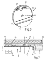
- the control element base 12 further comprises a projection 14, which extends in the vertical direction and thus in the y-direction over a bottom 15 of the control element base 12 down and represents a circular arc segment.
- Fig. 3 an exploded view of the operating element 10 is shown. It can be seen that on a top 16 of the control element base 12, a cylindrical elevation 17 is formed.
- a recess designed to be complementary thereto is formed, into which then the elevation 17 in the assembled state as shown in FIG Fig. 2 extends into it.
- the control element attachment 13 is rotatable relative to the control element base 12 and thus also to the cooktop plate 2 about an axis A which extends in the y-direction, wherein an associated operating condition adjustment takes place depending on specific rotational positions.
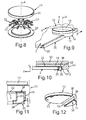
- Fig. 4 a perspective view of the control element base 12 is shown.
- the arc segment-shaped configuration of the supernatant 14 can be seen.
- two through holes 21 and 22 are formed, which are optically transparent. It can also be provided that the holes 21 and 22 are filled with a light-transmitting material, in which case in particular the light transmission for infrared light and / or light is provided in visible to the human spectral range.
- the control element attachment 13 is rotated about the axis A.
- the operating device 8 also comprises an evaluation unit. This can be designed, for example, working on an optical basis. For this purpose, corresponding light is then transmitted and received and passes through these openings or holes 21 and 22, so that it can be detected accordingly.
- the rotational position detection can also be realized via magnetic, inductive or capacitive sensors.
- an intermediate part 23 is formed, which is designed as a sliding and / or scratch protection element. It is formed in particular from a different to the control element base 12 material, preferably made of plastic.
- FIG. 5 showing an exploded view of the control element base 12 according to FIG Fig. 4 indicates that corresponding inserts 24 and 25, which, as already mentioned above, are translucent, are provided. Thereby, the entry of dirt or liquids in the openings 21 and 22 and thus also in the area below the control element base 12 can be prevented.
- FIG. 5 further openings 26 and 27 are provided, which are provided for the attachment of magnets.
- a holding element internal frame holding magnet is arranged, by means of which a magnetic interaction of this operating element internal retainer holding magnet 28 (FIGS. Fig. 7 ) and a magnetically interacting element in the control element attachment 13 is achieved.
- the control element attachment 13 is magnetically held on the control element base 12.
- a holding magnet 29 ( Fig. 7 ) arranged in the opening 26 .
- This eccentrically arranged holding magnet 29 magnetically interacts with a control element-external magnetically interacting element, in particular a counter-magnet 30 (FIG. Fig. 7 ), so that the control element base 12 is magnetically held on the control element holder 9.
- the control element-external, magnetically interacting element can also be a ferromagnetic part.
- Fig. 7 is also a sectional view of the execution in Fig. 2 shown along the section line VII-VII.
- a padding 31 is arranged in the operating element attachment 13, as it is then closer in the exploded view according to FIG Fig. 8 , which shows an exploded view of the control element attachment 13, is formed.
- the cushion 31 comprises at least at its ends respective interaction elements 32 for magnetic interaction, of which only a few, for clarity, are provided with the corresponding reference numerals.
- These interaction elements 32 come into magnetic interaction with the holding magnet 29, so that specific rotational positions of the operating element attachment 13 are latched and thereby corresponding latching positions are formed. For example, in particular set cooking stages can be perceived by the haptic perceptible locking positions when rotating the control element attachment 13 about the axis A and precisely adjusted.
- the control element attachment 13 comprises a cap 33 and a bottom 34.
- FIG. 9 a further embodiment of an operating device 8 is shown in a perspective partial view.
- an additional, designed as a separate component front strip 35 is provided. This is arranged adjacent to the front edge 20 of the hob plate 2.
- the front panel 35 is according to the sectional view in Fig. 10 formed higher in the vertical direction and thus in the y-direction, as the top 3 of the hob plate 2 is at its height level.
- a depression 36 is then configured on the underside 15 of the operating element base 12, into which the front strip 35 extends.
- the front panel 35 is shown in FIG Fig. 10 Also designed so that it engages under the hob plate 2 and thus is also partially formed below the hob plate 2 and extends accordingly.
- the front strip 35 bears against a side edge 37 on the front edge 20 of the hob plate 2.
- Fig. 11 is an enlarged view of Fig. 10 shown in a partial section with the front panel 35.
- the intermediate part 23 extends to the recess 36.
- a further intermediate part 38 is arranged on a protrusion lower side 39 of the supernatant 14, but moreover extends at least in places on the side wall 19 of the supernatant 14.
Applications Claiming Priority (1)
| Application Number | Priority Date | Filing Date | Title |
|---|---|---|---|
| DE102013217268.0A DE102013217268A1 (de) | 2013-08-29 | 2013-08-29 | Bedienvorrichtung für ein Haushaltsgerät mit einem nach unten stehenden Überstand an einem Bedienelementsockel, der magnetisch gehaltert ist |
Publications (2)
| Publication Number | Publication Date |
|---|---|
| EP2865949A1 true EP2865949A1 (fr) | 2015-04-29 |
| EP2865949B1 EP2865949B1 (fr) | 2016-11-02 |
Family
ID=51292823
Family Applications (1)
| Application Number | Title | Priority Date | Filing Date |
|---|---|---|---|
| EP14179957.7A Active EP2865949B1 (fr) | 2013-08-29 | 2014-08-06 | Dispositif de commande d'un appareil ménager doté d'un rebord inférieur sur un socle d'élément de commande à maintien magnétique |
Country Status (4)
| Country | Link |
|---|---|
| EP (1) | EP2865949B1 (fr) |
| DE (1) | DE102013217268A1 (fr) |
| ES (1) | ES2604604T3 (fr) |
| PL (1) | PL2865949T3 (fr) |
Cited By (2)
| Publication number | Priority date | Publication date | Assignee | Title |
|---|---|---|---|---|
| FR3050367A1 (fr) * | 2016-04-25 | 2017-10-27 | Eurokera | Plaque vitroceramique pour plan de travail ou meuble |
| EP3449189B1 (fr) * | 2016-04-25 | 2022-09-14 | Eurokera S.N.C. | Plaque vitroceramique pour plan de travail ou meuble |
Families Citing this family (5)
| Publication number | Priority date | Publication date | Assignee | Title |
|---|---|---|---|---|
| DE102017207388A1 (de) * | 2017-05-03 | 2018-11-08 | BSH Hausgeräte GmbH | Tragbares Bedienelement mit zumindest zwei separaten Platinen, sowie Bedienvorrichtung |
| DE102018209550A1 (de) | 2018-06-14 | 2019-12-19 | BSH Hausgeräte GmbH | Tragbares Bedienelement mit einem beweglich an einem Bedienteil angeordneten Dreherkennungsteil, sowie Bedienvorrichtung |
| DE102018209555A1 (de) | 2018-06-14 | 2019-12-19 | BSH Hausgeräte GmbH | Tragbares Bedienelement mit einer Basiseinheit und einem Bedienteil, welches relativ zur Basiseinheit kippbar ist, sowie Bedienvorrichtung für ein Gargerät |
| DE102018209552A1 (de) | 2018-06-14 | 2019-12-19 | BSH Hausgeräte GmbH | Tragbares Bedienelement mit Basiseinheit, Dreherkennungsteil und auf der Basiseinheit kippbar angeordnetem Bedienteil sowie Bedienvorrichtung für ein Gargerät |
| WO2023180220A1 (fr) * | 2022-03-21 | 2023-09-28 | BSH Hausgeräte GmbH | Élément de commande pour surface de cuisson, élément d'accouplement, dispositif de commande et surface de cuisson |
Citations (5)
| Publication number | Priority date | Publication date | Assignee | Title |
|---|---|---|---|---|
| DE10212953A1 (de) * | 2002-03-19 | 2003-10-02 | Ego Elektro Geraetebau Gmbh | Bedienvorrichtung für ein Elektrogerät |
| WO2004019150A1 (fr) * | 2002-08-14 | 2004-03-04 | BSH Bosch und Siemens Hausgeräte GmbH | Unite de commande pour appareil electromenager |
| DE102006026187A1 (de) | 2006-05-30 | 2007-12-06 | E.G.O. Elektro-Gerätebau GmbH | Bedieneinrichtung für ein Elektrogerät und Elektrogerät |
| US20100020042A1 (en) * | 2008-07-25 | 2010-01-28 | Visteon Global Technologies, Inc. | Touch-Sensitive Display Device With An Integrated Mechanical Operating Part For Motor Vehicles |
| DE102011086649A1 (de) | 2011-11-18 | 2013-05-23 | BSH Bosch und Siemens Hausgeräte GmbH | Bedieneinrichtung für ein Haushaltsgerät sowie Haushaltsgerät mit einer derartigen Bedieneinrichtung |
-
2013
- 2013-08-29 DE DE102013217268.0A patent/DE102013217268A1/de not_active Withdrawn
-
2014
- 2014-08-06 EP EP14179957.7A patent/EP2865949B1/fr active Active
- 2014-08-06 ES ES14179957.7T patent/ES2604604T3/es active Active
- 2014-08-06 PL PL14179957T patent/PL2865949T3/pl unknown
Patent Citations (5)
| Publication number | Priority date | Publication date | Assignee | Title |
|---|---|---|---|---|
| DE10212953A1 (de) * | 2002-03-19 | 2003-10-02 | Ego Elektro Geraetebau Gmbh | Bedienvorrichtung für ein Elektrogerät |
| WO2004019150A1 (fr) * | 2002-08-14 | 2004-03-04 | BSH Bosch und Siemens Hausgeräte GmbH | Unite de commande pour appareil electromenager |
| DE102006026187A1 (de) | 2006-05-30 | 2007-12-06 | E.G.O. Elektro-Gerätebau GmbH | Bedieneinrichtung für ein Elektrogerät und Elektrogerät |
| US20100020042A1 (en) * | 2008-07-25 | 2010-01-28 | Visteon Global Technologies, Inc. | Touch-Sensitive Display Device With An Integrated Mechanical Operating Part For Motor Vehicles |
| DE102011086649A1 (de) | 2011-11-18 | 2013-05-23 | BSH Bosch und Siemens Hausgeräte GmbH | Bedieneinrichtung für ein Haushaltsgerät sowie Haushaltsgerät mit einer derartigen Bedieneinrichtung |
Cited By (4)
| Publication number | Priority date | Publication date | Assignee | Title |
|---|---|---|---|---|
| FR3050367A1 (fr) * | 2016-04-25 | 2017-10-27 | Eurokera | Plaque vitroceramique pour plan de travail ou meuble |
| WO2017187070A1 (fr) * | 2016-04-25 | 2017-11-02 | Eurokera S.N.C. | Plaque vitroceramique pour plan de travail ou meuble |
| US11350739B2 (en) | 2016-04-25 | 2022-06-07 | Eurokera S.N.C. | Glass ceramic plate for worktop or furniture |
| EP3449189B1 (fr) * | 2016-04-25 | 2022-09-14 | Eurokera S.N.C. | Plaque vitroceramique pour plan de travail ou meuble |
Also Published As
| Publication number | Publication date |
|---|---|
| EP2865949B1 (fr) | 2016-11-02 |
| DE102013217268A1 (de) | 2015-03-05 |
| PL2865949T3 (pl) | 2017-03-31 |
| ES2604604T3 (es) | 2017-03-07 |
Similar Documents
| Publication | Publication Date | Title |
|---|---|---|
| EP2865949B1 (fr) | Dispositif de commande d'un appareil ménager doté d'un rebord inférieur sur un socle d'élément de commande à maintien magnétique | |
| DE102006026187B4 (de) | Bedieneinrichtung für ein Elektrogerät und Elektrogerät | |
| EP2543053B1 (fr) | Panneau pour appareil ménager muni d'un commutateur rotatif, et appareil ménager | |
| DE102011002410B4 (de) | Bedieneinrichtung für ein Elektrogerät | |
| DE102013212815A1 (de) | Bedienvorrichtung mit einem Bedienelement mit einem Haftelement an der Bedienelementunterseite sowie Haushaltsgerät mit einer derartigen Bedienvorrichtung | |
| DE102011007112A1 (de) | Bedieneinrichtung für ein Elektrogerät | |
| DE10212953B4 (de) | Bedienvorrichtung für ein Elektrogerät | |
| DE102014218493A1 (de) | Anzeige- und Bedienvorrichtung, insbesondere für ein Kraftfahrzeug, Bedienelement und Kraftfahrzeug | |
| DE10255676A1 (de) | Bedieneinheit für ein elektrisches Gerät | |
| DE102007056416A1 (de) | Bedienvorrichtung für ein Hausgerät | |
| EP2597377B1 (fr) | Dispositif d'utilisation pour un appareil ménager et appareil ménager destiné à la préparation d'aliments avec un tel dispositif d'utilisation | |
| DE102014216389A1 (de) | Bedienvorrichtung für ein Haushaltsgerät mit stabil positioniertem ringförmigen Bedienelement-Vorderteil und Haushaltsgerät mit einer derartigen Bedienvorrichtung | |
| DE102013212814A1 (de) | Bedienvorrichtung mit einem Bedienelement mit Magnete gehaltene Kappe und Sockel sowie Haushaltsgerät mit einer derartigen Bedienvorrichtung | |
| WO2018050542A1 (fr) | Dispositif de commande d'un ustensile de cuisine intégré | |
| DE102012101698A1 (de) | Fahrzeug-Steuerungsvorrichtung | |
| EP3348718B1 (fr) | Dispositif d'actionnement pour une soupape d'un dispositif d'écoulement pour un bassin | |
| DE102014200888A1 (de) | Bedienvorrichtung für ein Haushaltsgerät mit einem Kratzschutzelement an einer Unterseite eines abnehmbaren Bedienelements sowie Haushaltsgerät mit einer derartigen Bedienvorrichtung | |
| DE102010040675B4 (de) | Bedienvorrichtung für ein Hausgerät sowie Hausgerät mit einer derartigen Bedienvorrichtung | |
| DE102012201195B4 (de) | Bedienvorrichtung für ein Haushaltsgerät, Haushaltsgerät mit einer derartigen Bedienvorrichtung sowie Verfahren zum Betreiben einer Bedienvorrichtung | |
| EP3748234B1 (fr) | Dispositif de commande pour un appareil électrique et procédé de fonctionnement d'un appareil électrique | |
| EP3338027B1 (fr) | Dispositif de commande pour un appareil ménager comprenant un élément d'espacement et appareil ménager comprenant un dispositif de commande | |
| DE102017110009B4 (de) | Stellantrieb mit Bedienvorrichtung und zugehöriges Verfahren zur Bedienung | |
| EP2541152B1 (fr) | Dispositif de commande pour un appareil ménager et appareil ménager destiné à la préparation d'aliments avec un tel dispositif de commande | |
| DE102005035464A1 (de) | Hausgerätebedienvorrichtung | |
| EP2998655B1 (fr) | Appareil de cuisson à gaz |
Legal Events
| Date | Code | Title | Description |
|---|---|---|---|
| PUAI | Public reference made under article 153(3) epc to a published international application that has entered the european phase |
Free format text: ORIGINAL CODE: 0009012 |
|
| 17P | Request for examination filed |
Effective date: 20140806 |
|
| AK | Designated contracting states |
Kind code of ref document: A1 Designated state(s): AL AT BE BG CH CY CZ DE DK EE ES FI FR GB GR HR HU IE IS IT LI LT LU LV MC MK MT NL NO PL PT RO RS SE SI SK SM TR |
|
| AX | Request for extension of the european patent |
Extension state: BA ME |
|
| R17P | Request for examination filed (corrected) |
Effective date: 20151029 |
|
| RBV | Designated contracting states (corrected) |
Designated state(s): AL AT BE BG CH CY CZ DE DK EE ES FI FR GB GR HR HU IE IS IT LI LT LU LV MC MK MT NL NO PL PT RO RS SE SI SK SM TR |
|
| GRAP | Despatch of communication of intention to grant a patent |
Free format text: ORIGINAL CODE: EPIDOSNIGR1 |
|
| RIC1 | Information provided on ipc code assigned before grant |
Ipc: G05G 1/10 20060101ALI20160503BHEP Ipc: F24C 7/08 20060101AFI20160503BHEP |
|
| INTG | Intention to grant announced |
Effective date: 20160601 |
|
| GRAS | Grant fee paid |
Free format text: ORIGINAL CODE: EPIDOSNIGR3 |
|
| GRAA | (expected) grant |
Free format text: ORIGINAL CODE: 0009210 |
|
| AK | Designated contracting states |
Kind code of ref document: B1 Designated state(s): AL AT BE BG CH CY CZ DE DK EE ES FI FR GB GR HR HU IE IS IT LI LT LU LV MC MK MT NL NO PL PT RO RS SE SI SK SM TR |
|
| REG | Reference to a national code |
Ref country code: GB Ref legal event code: FG4D Free format text: NOT ENGLISH |
|
| REG | Reference to a national code |
Ref country code: AT Ref legal event code: REF Ref document number: 842235 Country of ref document: AT Kind code of ref document: T Effective date: 20161115 Ref country code: CH Ref legal event code: EP |
|
| REG | Reference to a national code |
Ref country code: IE Ref legal event code: FG4D Free format text: LANGUAGE OF EP DOCUMENT: GERMAN |
|
| REG | Reference to a national code |
Ref country code: DE Ref legal event code: R096 Ref document number: 502014001832 Country of ref document: DE |
|
| PG25 | Lapsed in a contracting state [announced via postgrant information from national office to epo] |
Ref country code: LV Free format text: LAPSE BECAUSE OF FAILURE TO SUBMIT A TRANSLATION OF THE DESCRIPTION OR TO PAY THE FEE WITHIN THE PRESCRIBED TIME-LIMIT Effective date: 20161102 |
|
| REG | Reference to a national code |
Ref country code: ES Ref legal event code: FG2A Ref document number: 2604604 Country of ref document: ES Kind code of ref document: T3 Effective date: 20170307 |
|
| REG | Reference to a national code |
Ref country code: NL Ref legal event code: MP Effective date: 20161102 |
|
| REG | Reference to a national code |
Ref country code: LT Ref legal event code: MG4D |
|
| PG25 | Lapsed in a contracting state [announced via postgrant information from national office to epo] |
Ref country code: NO Free format text: LAPSE BECAUSE OF FAILURE TO SUBMIT A TRANSLATION OF THE DESCRIPTION OR TO PAY THE FEE WITHIN THE PRESCRIBED TIME-LIMIT Effective date: 20170202 Ref country code: GR Free format text: LAPSE BECAUSE OF FAILURE TO SUBMIT A TRANSLATION OF THE DESCRIPTION OR TO PAY THE FEE WITHIN THE PRESCRIBED TIME-LIMIT Effective date: 20170203 Ref country code: NL Free format text: LAPSE BECAUSE OF FAILURE TO SUBMIT A TRANSLATION OF THE DESCRIPTION OR TO PAY THE FEE WITHIN THE PRESCRIBED TIME-LIMIT Effective date: 20161102 Ref country code: SE Free format text: LAPSE BECAUSE OF FAILURE TO SUBMIT A TRANSLATION OF THE DESCRIPTION OR TO PAY THE FEE WITHIN THE PRESCRIBED TIME-LIMIT Effective date: 20161102 Ref country code: LT Free format text: LAPSE BECAUSE OF FAILURE TO SUBMIT A TRANSLATION OF THE DESCRIPTION OR TO PAY THE FEE WITHIN THE PRESCRIBED TIME-LIMIT Effective date: 20161102 |
|
| PG25 | Lapsed in a contracting state [announced via postgrant information from national office to epo] |
Ref country code: PT Free format text: LAPSE BECAUSE OF FAILURE TO SUBMIT A TRANSLATION OF THE DESCRIPTION OR TO PAY THE FEE WITHIN THE PRESCRIBED TIME-LIMIT Effective date: 20170302 Ref country code: FI Free format text: LAPSE BECAUSE OF FAILURE TO SUBMIT A TRANSLATION OF THE DESCRIPTION OR TO PAY THE FEE WITHIN THE PRESCRIBED TIME-LIMIT Effective date: 20161102 Ref country code: RS Free format text: LAPSE BECAUSE OF FAILURE TO SUBMIT A TRANSLATION OF THE DESCRIPTION OR TO PAY THE FEE WITHIN THE PRESCRIBED TIME-LIMIT Effective date: 20161102 Ref country code: IS Free format text: LAPSE BECAUSE OF FAILURE TO SUBMIT A TRANSLATION OF THE DESCRIPTION OR TO PAY THE FEE WITHIN THE PRESCRIBED TIME-LIMIT Effective date: 20170302 Ref country code: HR Free format text: LAPSE BECAUSE OF FAILURE TO SUBMIT A TRANSLATION OF THE DESCRIPTION OR TO PAY THE FEE WITHIN THE PRESCRIBED TIME-LIMIT Effective date: 20161102 |
|
| PG25 | Lapsed in a contracting state [announced via postgrant information from national office to epo] |
Ref country code: RO Free format text: LAPSE BECAUSE OF FAILURE TO SUBMIT A TRANSLATION OF THE DESCRIPTION OR TO PAY THE FEE WITHIN THE PRESCRIBED TIME-LIMIT Effective date: 20161102 Ref country code: DK Free format text: LAPSE BECAUSE OF FAILURE TO SUBMIT A TRANSLATION OF THE DESCRIPTION OR TO PAY THE FEE WITHIN THE PRESCRIBED TIME-LIMIT Effective date: 20161102 Ref country code: EE Free format text: LAPSE BECAUSE OF FAILURE TO SUBMIT A TRANSLATION OF THE DESCRIPTION OR TO PAY THE FEE WITHIN THE PRESCRIBED TIME-LIMIT Effective date: 20161102 Ref country code: CZ Free format text: LAPSE BECAUSE OF FAILURE TO SUBMIT A TRANSLATION OF THE DESCRIPTION OR TO PAY THE FEE WITHIN THE PRESCRIBED TIME-LIMIT Effective date: 20161102 Ref country code: SK Free format text: LAPSE BECAUSE OF FAILURE TO SUBMIT A TRANSLATION OF THE DESCRIPTION OR TO PAY THE FEE WITHIN THE PRESCRIBED TIME-LIMIT Effective date: 20161102 |
|
| REG | Reference to a national code |
Ref country code: DE Ref legal event code: R097 Ref document number: 502014001832 Country of ref document: DE |
|
| REG | Reference to a national code |
Ref country code: FR Ref legal event code: PLFP Year of fee payment: 4 |
|
| PG25 | Lapsed in a contracting state [announced via postgrant information from national office to epo] |
Ref country code: BG Free format text: LAPSE BECAUSE OF FAILURE TO SUBMIT A TRANSLATION OF THE DESCRIPTION OR TO PAY THE FEE WITHIN THE PRESCRIBED TIME-LIMIT Effective date: 20170202 Ref country code: SM Free format text: LAPSE BECAUSE OF FAILURE TO SUBMIT A TRANSLATION OF THE DESCRIPTION OR TO PAY THE FEE WITHIN THE PRESCRIBED TIME-LIMIT Effective date: 20161102 |
|
| PLBE | No opposition filed within time limit |
Free format text: ORIGINAL CODE: 0009261 |
|
| STAA | Information on the status of an ep patent application or granted ep patent |
Free format text: STATUS: NO OPPOSITION FILED WITHIN TIME LIMIT |
|
| 26N | No opposition filed |
Effective date: 20170803 |
|
| PG25 | Lapsed in a contracting state [announced via postgrant information from national office to epo] |
Ref country code: SI Free format text: LAPSE BECAUSE OF FAILURE TO SUBMIT A TRANSLATION OF THE DESCRIPTION OR TO PAY THE FEE WITHIN THE PRESCRIBED TIME-LIMIT Effective date: 20161102 |
|
| REG | Reference to a national code |
Ref country code: CH Ref legal event code: PL |
|
| PG25 | Lapsed in a contracting state [announced via postgrant information from national office to epo] |
Ref country code: MC Free format text: LAPSE BECAUSE OF FAILURE TO SUBMIT A TRANSLATION OF THE DESCRIPTION OR TO PAY THE FEE WITHIN THE PRESCRIBED TIME-LIMIT Effective date: 20161102 |
|
| PG25 | Lapsed in a contracting state [announced via postgrant information from national office to epo] |
Ref country code: CH Free format text: LAPSE BECAUSE OF NON-PAYMENT OF DUE FEES Effective date: 20170831 Ref country code: LI Free format text: LAPSE BECAUSE OF NON-PAYMENT OF DUE FEES Effective date: 20170831 |
|
| REG | Reference to a national code |
Ref country code: IE Ref legal event code: MM4A |
|
| REG | Reference to a national code |
Ref country code: BE Ref legal event code: MM Effective date: 20170831 |
|
| PG25 | Lapsed in a contracting state [announced via postgrant information from national office to epo] |
Ref country code: LU Free format text: LAPSE BECAUSE OF NON-PAYMENT OF DUE FEES Effective date: 20170806 |
|
| PG25 | Lapsed in a contracting state [announced via postgrant information from national office to epo] |
Ref country code: IE Free format text: LAPSE BECAUSE OF NON-PAYMENT OF DUE FEES Effective date: 20170806 |
|
| REG | Reference to a national code |
Ref country code: FR Ref legal event code: PLFP Year of fee payment: 5 |
|
| PG25 | Lapsed in a contracting state [announced via postgrant information from national office to epo] |
Ref country code: BE Free format text: LAPSE BECAUSE OF NON-PAYMENT OF DUE FEES Effective date: 20170831 |
|
| PG25 | Lapsed in a contracting state [announced via postgrant information from national office to epo] |
Ref country code: MT Free format text: LAPSE BECAUSE OF FAILURE TO SUBMIT A TRANSLATION OF THE DESCRIPTION OR TO PAY THE FEE WITHIN THE PRESCRIBED TIME-LIMIT Effective date: 20161102 |
|
| PG25 | Lapsed in a contracting state [announced via postgrant information from national office to epo] |
Ref country code: HU Free format text: LAPSE BECAUSE OF FAILURE TO SUBMIT A TRANSLATION OF THE DESCRIPTION OR TO PAY THE FEE WITHIN THE PRESCRIBED TIME-LIMIT; INVALID AB INITIO Effective date: 20140806 |
|
| PG25 | Lapsed in a contracting state [announced via postgrant information from national office to epo] |
Ref country code: CY Free format text: LAPSE BECAUSE OF FAILURE TO SUBMIT A TRANSLATION OF THE DESCRIPTION OR TO PAY THE FEE WITHIN THE PRESCRIBED TIME-LIMIT Effective date: 20161102 |
|
| PGFP | Annual fee paid to national office [announced via postgrant information from national office to epo] |
Ref country code: TR Payment date: 20190729 Year of fee payment: 6 |
|
| PG25 | Lapsed in a contracting state [announced via postgrant information from national office to epo] |
Ref country code: MK Free format text: LAPSE BECAUSE OF FAILURE TO SUBMIT A TRANSLATION OF THE DESCRIPTION OR TO PAY THE FEE WITHIN THE PRESCRIBED TIME-LIMIT Effective date: 20161102 |
|
| PGFP | Annual fee paid to national office [announced via postgrant information from national office to epo] |
Ref country code: PL Payment date: 20190726 Year of fee payment: 6 |
|
| PG25 | Lapsed in a contracting state [announced via postgrant information from national office to epo] |
Ref country code: AL Free format text: LAPSE BECAUSE OF FAILURE TO SUBMIT A TRANSLATION OF THE DESCRIPTION OR TO PAY THE FEE WITHIN THE PRESCRIBED TIME-LIMIT Effective date: 20161102 |
|
| REG | Reference to a national code |
Ref country code: AT Ref legal event code: MM01 Ref document number: 842235 Country of ref document: AT Kind code of ref document: T Effective date: 20190806 |
|
| PG25 | Lapsed in a contracting state [announced via postgrant information from national office to epo] |
Ref country code: AT Free format text: LAPSE BECAUSE OF NON-PAYMENT OF DUE FEES Effective date: 20190806 |
|
| PG25 | Lapsed in a contracting state [announced via postgrant information from national office to epo] |
Ref country code: TR Free format text: LAPSE BECAUSE OF NON-PAYMENT OF DUE FEES Effective date: 20200806 |
|
| PG25 | Lapsed in a contracting state [announced via postgrant information from national office to epo] |
Ref country code: PL Free format text: LAPSE BECAUSE OF NON-PAYMENT OF DUE FEES Effective date: 20200806 |
|
| REG | Reference to a national code |
Ref country code: DE Ref legal event code: R084 Ref document number: 502014001832 Country of ref document: DE |
|
| PGFP | Annual fee paid to national office [announced via postgrant information from national office to epo] |
Ref country code: IT Payment date: 20230831 Year of fee payment: 10 Ref country code: GB Payment date: 20230824 Year of fee payment: 10 Ref country code: ES Payment date: 20230918 Year of fee payment: 10 |
|
| PGFP | Annual fee paid to national office [announced via postgrant information from national office to epo] |
Ref country code: FR Payment date: 20230821 Year of fee payment: 10 Ref country code: DE Payment date: 20230831 Year of fee payment: 10 |