EP2865831A2 - Schloss - Google Patents
Schloss Download PDFInfo
- Publication number
- EP2865831A2 EP2865831A2 EP20140189720 EP14189720A EP2865831A2 EP 2865831 A2 EP2865831 A2 EP 2865831A2 EP 20140189720 EP20140189720 EP 20140189720 EP 14189720 A EP14189720 A EP 14189720A EP 2865831 A2 EP2865831 A2 EP 2865831A2
- Authority
- EP
- European Patent Office
- Prior art keywords
- latch
- arm
- spring
- push rod
- lock
- Prior art date
- Legal status (The legal status is an assumption and is not a legal conclusion. Google has not performed a legal analysis and makes no representation as to the accuracy of the status listed.)
- Granted
Links
- 238000004519 manufacturing process Methods 0.000 description 3
- 230000006835 compression Effects 0.000 description 1
- 238000007906 compression Methods 0.000 description 1
- 238000010276 construction Methods 0.000 description 1
- 238000006073 displacement reaction Methods 0.000 description 1
- 230000000694 effects Effects 0.000 description 1
- 230000002349 favourable effect Effects 0.000 description 1
- 230000037431 insertion Effects 0.000 description 1
- 238000003780 insertion Methods 0.000 description 1
- 239000007788 liquid Substances 0.000 description 1
Images

Classifications
-
- E—FIXED CONSTRUCTIONS
- E05—LOCKS; KEYS; WINDOW OR DOOR FITTINGS; SAFES
- E05C—BOLTS OR FASTENING DEVICES FOR WINGS, SPECIALLY FOR DOORS OR WINDOWS
- E05C9/00—Arrangements of simultaneously actuated bolts or other securing devices at well-separated positions on the same wing
- E05C9/18—Details of fastening means or of fixed retaining means for the ends of bars
- E05C9/1825—Fastening means
- E05C9/1833—Fastening means performing sliding movements
- E05C9/1841—Fastening means performing sliding movements perpendicular to actuating bar
-
- E—FIXED CONSTRUCTIONS
- E05—LOCKS; KEYS; WINDOW OR DOOR FITTINGS; SAFES
- E05B—LOCKS; ACCESSORIES THEREFOR; HANDCUFFS
- E05B59/00—Locks with latches separate from the lock-bolts or with a plurality of latches or lock-bolts
-
- E—FIXED CONSTRUCTIONS
- E05—LOCKS; KEYS; WINDOW OR DOOR FITTINGS; SAFES
- E05B—LOCKS; ACCESSORIES THEREFOR; HANDCUFFS
- E05B55/00—Locks in which a sliding latch is used also as a locking bolt
-
- E—FIXED CONSTRUCTIONS
- E05—LOCKS; KEYS; WINDOW OR DOOR FITTINGS; SAFES
- E05B—LOCKS; ACCESSORIES THEREFOR; HANDCUFFS
- E05B57/00—Locks in which a pivoted latch is used also as locking means
-
- E—FIXED CONSTRUCTIONS
- E05—LOCKS; KEYS; WINDOW OR DOOR FITTINGS; SAFES
- E05C—BOLTS OR FASTENING DEVICES FOR WINGS, SPECIALLY FOR DOORS OR WINDOWS
- E05C9/00—Arrangements of simultaneously actuated bolts or other securing devices at well-separated positions on the same wing
- E05C9/02—Arrangements of simultaneously actuated bolts or other securing devices at well-separated positions on the same wing with one sliding bar for fastening when moved in one direction and unfastening when moved in opposite direction; with two sliding bars moved in the same direction when fastening or unfastening
-
- E—FIXED CONSTRUCTIONS
- E05—LOCKS; KEYS; WINDOW OR DOOR FITTINGS; SAFES
- E05B—LOCKS; ACCESSORIES THEREFOR; HANDCUFFS
- E05B15/00—Other details of locks; Parts for engagement by bolts of fastening devices
- E05B15/04—Spring arrangements in locks
- E05B2015/0468—Spring arrangements in locks made of one piece with a lock part
Definitions
- the invention relates to a lock according to the preamble of claim 1.
- a latch lever is provided, which is taken along with a displacement of the push rod in the direction of the open position of the locking elements of the push rod and pivoted, whereby the case is withdrawn.
- the aim of the invention is to avoid this disadvantage and to propose a lock of the type mentioned that allows for larger tolerances proper operation of a multiple locking.
- the push rod can still be moved to the spring travel of this interacting with the latch lever to the over the push rod to be able to completely pull in the controlled additional bar.
- the additional bolts can also be configured as desired.
- the push rod to the spring travel are moved, after which given by overcoming the spring travel of the spring-trained arm of the latch lever stop secure entrainment of the case or the latch bolt is ensured.
- the spring-trained arm of the latch lever goes back to its normal position after releasing the clamp.
- the features of claim 2 may be provided. In this way, results in a very simple construction, which also results in a correspondingly small spring travel and after overcoming the predetermined by the slot travel a secure stop and thus secure entrainment of the remaining latch lever is ensured.
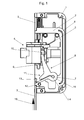
- the lock is shown with removed housing cover.
- a link 2 is guided, which connects two parts of a push rod 3, whose drive is not shown and, for example. can be done via a lock cylinder or a nut with a corresponding gear.
- a latch bolt 4 is held substantially perpendicular to the push rod 3 slidably.
- the latch bolt 4 by a latch spring 5 against his in the Fig. 1 shown biased position shown, wherein the latch spring 5 is held on a pin 6 fixed in the housing 1.
- a second arm 11 of the latch lever 8 is applied to a driver 12 of the link 2, which is thus moved with the push rod 3.
- This second arm 11 of the latch lever 8 has an open-edged slot 13 which, as shown, extends as far as a bore 14 for receiving the axle 7.
- the slot can be guided, as shown, also kinked. This results in a spring action on the connecting portion 15 of the two arms 9, 11 of the latch lever 8.
- the spring constant of the two divided by the slot 13 parts of the arm 11 is higher than that of the latch spring 5, but as low as possible to a liquid use of entire hubs of the castle to allow.
- the path of the push rod 3 is not sufficient for the complete retraction of the latch bolt 4, to completely withdraw the additional bar, not shown, also shown by the push rod 3, the push rod 3 to the way the width of the Slot 13 of the arm 11 of the latch lever 8 are moved further ( Figure 3 ).
- manufacturing tolerances can be easily compensated.
Landscapes
- Engineering & Computer Science (AREA)
- Mechanical Engineering (AREA)
- Lock And Its Accessories (AREA)
Abstract
Description
- Die Erfindung bezieht sich auf ein Schloss gemäß dem Oberbegriff des Anspruches 1.
- Bei derartigen Schlössern ist ein Fallenhebel vorgesehen, der bei einem Verschieben der Schubstange in Richtung der Offenstellung der Riegelelemente von der Schubstange mitgenommen und verschwenkt wird, wodurch die Falle zurückgezogen wird. Dabei ergibt sich das Problem, dass bei der Herstellung der erforderlichen Einzelteile Toleranzen unvermeidbar sind. Dadurch können sich Probleme in der Weise ergeben, dass die Riegel der Mehrfachverriegelung nicht vollständig zurückgezogen werden können, da nach vollständigem Einziehen der Falle kein weiterer Hubweg für die Schubstange mehr verbleibt, wodurch sich entsprechende Probleme beim Betrieb einer solchen Mehrfachverriegelung ergeben.
- Ziel der Erfindung ist es, diesen Nachteil zu vermeiden und ein Schloss der eingangs erwähnten Art vorzuschlagen, das auch bei größeren Toleranzen einen einwandfreien Betrieb einer Mehrfachverriegelung ermöglicht.
- Erfindungsgemäß wird dies durch die kennzeichnenden Merkmale des Anspruchs 1 erreicht.
- Durch die vorgeschlagenen Maßnahmen ist sichergestellt, dass, bei einer/einem sich bereits in der zurückgezogenen Endlage befindlichen Falle, bzw. Fallenriegel, Riegel oder Schwenkriegel, die Schubstange noch um den Federweg des mit dieser zusammenwirkenden Fallenhebels weiterbewegt werden kann, um die über die Schubstange gesteuerten Zusatzriegel vollständig einziehen zu können. Es versteht sich, dass die Zusatzriegel ebenfalls beliebig ausgestaltet sein können.
- Weiters kann, bei einem aufgrund von höheren auf die Falle, bzw. den Fallenriegel, Riegel oder Schwenkriegel, einwirkenden Seitenkräften auftretenden Klemmen der Falle in Schließstellung, die Schubstange um den Federweg bewegt werden, wonach durch den nach Überwindung des Federweges des federnd ausgebildeten Armes des Fallenhebels gegebenen Anschlag eine sichere Mitnahme der Falle bzw. des Fallenriegels sichergestellt ist. Dabei geht der federnd ausgebildete Arm des Fallenhebels nach dem Lösen der Klemmung wieder in seine Normallage zurück.
- Aufgrund des Federweges des mit der Schubstange, bzw. mit deren Mitnehmer, zusammenwirkenden Armes des Fallenhebels können bei der Herstellung der einzelnen Teile eines erfindungsgemäßen Schlosses relativ große Toleranzen zugelassen werden, ohne dass es dadurch bei der Verwendung des Schlosses zu Problemen kommt.
- Nach einem weiteren Merkmal können die Merkmale des Anspruches 2 vorgesehen sein. Auf diese Weise ergibt sich eine sehr einfache Konstruktion, wobei sich auch ein entsprechend kleiner Federweg ergibt und nach Überwindung des durch den Schlitz vorgegebenen Federwegs ein sicherer Anschlag und damit eine sichere Mitnahme des übrigen Fallenhebels sichergestellt ist.
- In diesem Zusammenhang ist es vorteilhaft, die Merkmale des Anspruches 3 vorzusehen, wodurch sich eine sehr günstige Federcharakteristik erreichen lässt.
- Die Erfindung wird nun anhand der Zeichnung näher erläutert, wobei sich die Beschreibung auf die wesentlichen Teile der Erfindung beschränkt. Dabei zeigen:
-
Fig. 1 ein erfindungsgemäßes Schloss mit ausgeschobenem Fallenriegel und der Schubstange in der Sperrstellung von Zusatzriegeln, -
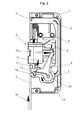
Fig. 2 das Schloss nach derFig. 1 mit vollständig zurückgezogenem Fallenriegel, wobei sich die Schubstange in einer den zurückgezogenen Zusatzriegeln entsprechenden Stellung befindet, und -
Fig. 3 das Schloss nach denFig. 1 und2 mit in einer Endstellung befindlicher Schubstange, wo der verbleibende Hub des Federwegs des Fallenhebels mit verwendet wird. - Das Schloss ist mit abgenommenem Gehäusedeckel dargestellt. In einem Gehäuse 1 ist eine Kulisse 2 geführt, die zwei Teile einer Schubstange 3 miteinander verbindet, deren Antrieb nicht dargestellt ist und z.B. über einen Schließzylinder oder eine Nuss mit entsprechendem Getriebe erfolgen kann.
- In dem Gehäuse 1 ist weiters ein Fallenriegel 4 im Wesentlichen senkrecht zur Schubstange 3 verschiebbar gehalten. Dabei ist der Fallenriegel 4 von einer Fallenfeder 5 gegen seine in der
Fig. 1 dargestellte ausgeschobene Stellung vorgespannt, wobei die Fallenfeder 5 an einem im Gehäuse 1 befestigten Zapfen 6 gehalten ist. - Ein um eine Achse 7 drehbar gehaltener Fallenhebel 8 greift mit einem Arm 9 in eine Nut 10 des Fallenriegels 4 ein und wird daher in Ausschieberichtung des Fallenriegels 4 von diesem mitgenommen und nimmt seinerseits den Fallenriegel 4 in Einschieberichtung des Fallenriegels 4 entgegen der Kraft der Fallenfeder 5 mit.
- Ein zweiter Arm 11 des Fallenhebels 8 liegt an einem Mitnehmer 12 der Kulisse 2 an, der somit mit der Schubstange 3 mitbewegt wird. Dieser zweite Arm 11 des Fallenhebels 8 weist einen randoffenen Schlitz 13 auf, der sich, wie dargestellt bis zu einer Bohrung 14 zur Aufnahme der Achse 7 erstreckt. Der Schlitz kann dabei, wie gezeigt, auch geknickt geführt sein. Dadurch ergibt sich eine Federwirkung über den Verbindungsbereich 15 der beiden Arme 9, 11 des Fallenhebels 8. Die Federkonstante der beiden durch den Schlitz 13 geteilten Teile des Armes 11 ist höher als jene der Fallenfeder 5, jedoch so gering wie möglich um eine flüssige Benutzung des gesamten Hubs des Schlosses zu ermöglichen.
- Wird die Schubstange 3 nach oben in Richtung des Pfeils 16 verschoben, so wird der Fallenhebel 8 über seinen an dem Mitnehmer 12 anliegenden Arm 11 im Uhrzeigersinn verschwenkt und zieht über seinen Arm 9 den Fallenriegel 4 entgegen der Kraft der Fallenfeder 5 zurück (
Fig. 2 ). - Reicht dabei der Weg der Schubstange 3 bis zum vollständigen Zurückziehen des Fallenriegels 4 nicht aus, um die von der Schubstange 3 ebenfalls gesteuerten, nicht dargestellten Zusatzriegel vollständig zurückzuziehen, so kann die Schubstange 3 um den Weg der Breite des Schlitzes 13 des Armes 11 des Fallenhebels 8 weiterbewegt werden (
Fig.3 ). Dadurch können herstellungsbedingte Toleranzen sehr einfach ausgeglichen werden. - Falls es aufgrund von höheren auf den Fallenriegel 4 einwirkenden seitlichen Kräften zu einer Klemmung des Fallenriegels 4 in Schließstellung kommt, so kommt es bei einer Bewegung der Schubstange 3 in Richtung des Pfeils 16 (
Fig. 1 und2 ) zum Öffnen des Schlosses zuerst zu einem Zusammendrücken des Schlitzes 13 in dessen äußerem Bereich bis die beiden durch den Schlitz 13 getrennten Teile des Armes 11 in deren äußeren Bereichen aneinander anliegen und eine sichere Mitnahme des Armes 11 des Fallenhebels 8 erfolgt. Dadurch wird der Fallenhebel 8 verschwenkt und der Fallenriegel 4 in jedem Fall zurückgezogen. Sobald die Rückzugsbewegung des Fallenriegels 4 einsetzt und die Klemmwirkung aufgehoben ist, vermindert sich die für das Zurückziehen des Fallenriegels erforderliche Kraft und der Schlitz 13 öffnet sich wieder aufgrund der größeren Federkonstante. Falls bei Erreichung der zurückgezogenen Endstellung des Fallenriegels 4 noch ein Überhub zum vollständigen Zurückziehen der von der Schubstange 3 gesteuerten Zusatzriegel erforderlich sein sollte, so steht dieser Überhub durch Zusammendrücken des Schlitzes 13 wieder zur Verfügung.
Claims (3)
- Schloss für eine Mehrfachverriegelung mit einem Fallenhebel (8) zur Betätigung einer gegen ihre ausgeschobene Stellung mittels einer Fallenfeder (5) federbelasteten Falle, bzw. einem Fallenriegel (4), Riegel oder Schwenkriegel, wobei der um eine Achse (7) drehbar gehaltene Fallenhebel (8) zwei Arme(9, 11) aufweist, von denen ein Arm (9) mit der Falle (4) zusammenwirkt und der andere Arm (11) mit einem Mitnehmer (12) der Schubstange (3) zusammenwirkt, dadurch gekennzeichnet, dass ein Arm (11) des Fallenhebels (8) federnd ausgebildet ist und dessen Federkonstante größer als jene der Fallenfeder (5) ist.
- Schloss nach Anspruch 1, dadurch gekennzeichnet, dass der mit dem Mitnehmer (12) der Schubstange (3) zusammenwirkende Arm (11) des Fallenhebels (8) einen randoffenen Schlitz (13) aufweist, der diesen Arm (11) zumindest in seinem äußeren Bereich unterteilt und dadurch dieser federnd ausgebildet ist.
- Schloss nach Anspruch 2, dadurch gekennzeichnet, dass sich der Schlitz (13) bis zur Bohrung (14) des Fallenhebels (8) zur Aufnahme der Achse (7) erstreckt.
Applications Claiming Priority (1)
| Application Number | Priority Date | Filing Date | Title |
|---|---|---|---|
| ATA50690/2013A AT515377B1 (de) | 2013-10-25 | 2013-10-25 | Schloss |
Publications (3)
| Publication Number | Publication Date |
|---|---|
| EP2865831A2 true EP2865831A2 (de) | 2015-04-29 |
| EP2865831A3 EP2865831A3 (de) | 2016-03-30 |
| EP2865831B1 EP2865831B1 (de) | 2018-01-03 |
Family
ID=51794739
Family Applications (1)
| Application Number | Title | Priority Date | Filing Date |
|---|---|---|---|
| EP14189720.7A Not-in-force EP2865831B1 (de) | 2013-10-25 | 2014-10-21 | Schloss |
Country Status (2)
| Country | Link |
|---|---|
| EP (1) | EP2865831B1 (de) |
| AT (1) | AT515377B1 (de) |
Family Cites Families (6)
| Publication number | Priority date | Publication date | Assignee | Title |
|---|---|---|---|---|
| FR2319760A1 (fr) * | 1975-07-28 | 1977-02-25 | Drevet Guy | Cremone-serrure |
| DE29605517U1 (de) * | 1996-03-26 | 1997-07-24 | Gretsch-Unitas GmbH Baubeschläge, 71254 Ditzingen | Verriegelungseinrichtung |
| AT409397B (de) * | 2000-06-20 | 2002-07-25 | Grundmann Beschlagtechnik Gmbh | Schloss |
| DE20119950U1 (de) * | 2001-12-04 | 2002-04-04 | Gretsch-Unitas GmbH Baubeschläge, 71254 Ditzingen | Zusatzriegelschloss |
| DE102004037915A1 (de) * | 2004-08-05 | 2006-02-23 | Roto Frank Ag | Verriegelungsvorrichtung zwischen einem Flügel und einem festen Rahmen einer Tür, eines Fensters oder dergleichen sowie Verriegelungsanordnung mit wenigstens einer derartigen Verriegelungsvorrichtung |
| DE202013000920U1 (de) * | 2013-01-30 | 2013-02-26 | Kfv Karl Fliether Gmbh & Co. Kg | Panikschloss |
-
2013
- 2013-10-25 AT ATA50690/2013A patent/AT515377B1/de not_active IP Right Cessation
-
2014
- 2014-10-21 EP EP14189720.7A patent/EP2865831B1/de not_active Not-in-force
Non-Patent Citations (1)
| Title |
|---|
| None |
Also Published As
| Publication number | Publication date |
|---|---|
| AT515377B1 (de) | 2015-10-15 |
| AT515377A1 (de) | 2015-08-15 |
| EP2865831A3 (de) | 2016-03-30 |
| EP2865831B1 (de) | 2018-01-03 |
Similar Documents
| Publication | Publication Date | Title |
|---|---|---|
| EP3109384A1 (de) | Schliessvorrichtung mit starker riegeldruckfeder | |
| EP2840186B1 (de) | Befestigungsvorrichtung für eine Befestigung eines Frontladers an einem Arbeitsfahrzeug | |
| DE102013100275A1 (de) | Treibriegelschloss mit überdrückbarem Riegelschieber | |
| AT513469B1 (de) | Türschloss | |
| AT409397B (de) | Schloss | |
| DE102015000606A1 (de) | Verriegelungsvorrichtung für einen schwenkbar gelagerten Flügel | |
| EP3805493A2 (de) | Modular aufgebautes schloss mit panikfunktion | |
| AT513470B1 (de) | Türschloss | |
| EP2865831B1 (de) | Schloss | |
| DE102016200589A1 (de) | Türgriffanordnung | |
| EP3215696B1 (de) | Schloss | |
| EP2085543B1 (de) | Schloss | |
| EP2290180B1 (de) | Schloss | |
| DE10129349A1 (de) | Schloss | |
| EP2808468A2 (de) | Verriegelungseinheit für eine Schließanlage | |
| EP2754795B1 (de) | Gegenkasten oder Einsteckschloss | |
| AT515775B1 (de) | Schloss | |
| EP3109382B1 (de) | Schloss | |
| DE102017000346B4 (de) | Schloss mit Fallensperre | |
| AT516516B1 (de) | Schloss | |
| DE102016118125A1 (de) | Federpaket mit Pleuelansteuerung | |
| DE102023128399A1 (de) | Schloss mit umwendbarer Falle | |
| AT14920U1 (de) | Schloss | |
| AT14921U1 (de) | Schloss | |
| AT15083U1 (de) | Schloss |
Legal Events
| Date | Code | Title | Description |
|---|---|---|---|
| PUAI | Public reference made under article 153(3) epc to a published international application that has entered the european phase |
Free format text: ORIGINAL CODE: 0009012 |
|
| 17P | Request for examination filed |
Effective date: 20141021 |
|
| AK | Designated contracting states |
Kind code of ref document: A2 Designated state(s): AL AT BE BG CH CY CZ DE DK EE ES FI FR GB GR HR HU IE IS IT LI LT LU LV MC MK MT NL NO PL PT RO RS SE SI SK SM TR |
|
| AX | Request for extension of the european patent |
Extension state: BA ME |
|
| PUAL | Search report despatched |
Free format text: ORIGINAL CODE: 0009013 |
|
| AK | Designated contracting states |
Kind code of ref document: A3 Designated state(s): AL AT BE BG CH CY CZ DE DK EE ES FI FR GB GR HR HU IE IS IT LI LT LU LV MC MK MT NL NO PL PT RO RS SE SI SK SM TR |
|
| AX | Request for extension of the european patent |
Extension state: BA ME |
|
| RIC1 | Information provided on ipc code assigned before grant |
Ipc: E05B 15/04 20060101ALI20160222BHEP Ipc: E05C 9/18 20060101AFI20160222BHEP |
|
| R17P | Request for examination filed (corrected) |
Effective date: 20160824 |
|
| RBV | Designated contracting states (corrected) |
Designated state(s): AL AT BE BG CH CY CZ DE DK EE ES FI FR GB GR HR HU IE IS IT LI LT LU LV MC MK MT NL NO PL PT RO RS SE SI SK SM TR |
|
| GRAP | Despatch of communication of intention to grant a patent |
Free format text: ORIGINAL CODE: EPIDOSNIGR1 |
|
| INTG | Intention to grant announced |
Effective date: 20170215 |
|
| GRAS | Grant fee paid |
Free format text: ORIGINAL CODE: EPIDOSNIGR3 |
|
| GRAJ | Information related to disapproval of communication of intention to grant by the applicant or resumption of examination proceedings by the epo deleted |
Free format text: ORIGINAL CODE: EPIDOSDIGR1 |
|
| GRAL | Information related to payment of fee for publishing/printing deleted |
Free format text: ORIGINAL CODE: EPIDOSDIGR3 |
|
| GRAP | Despatch of communication of intention to grant a patent |
Free format text: ORIGINAL CODE: EPIDOSNIGR1 |
|
| INTG | Intention to grant announced |
Effective date: 20170721 |
|
| GRAA | (expected) grant |
Free format text: ORIGINAL CODE: 0009210 |
|
| AK | Designated contracting states |
Kind code of ref document: B1 Designated state(s): AL AT BE BG CH CY CZ DE DK EE ES FI FR GB GR HR HU IE IS IT LI LT LU LV MC MK MT NL NO PL PT RO RS SE SI SK SM TR |
|
| REG | Reference to a national code |
Ref country code: GB Ref legal event code: FG4D Free format text: NOT ENGLISH |
|
| REG | Reference to a national code |
Ref country code: CH Ref legal event code: EP Ref country code: AT Ref legal event code: REF Ref document number: 960431 Country of ref document: AT Kind code of ref document: T Effective date: 20180115 |
|
| REG | Reference to a national code |
Ref country code: IE Ref legal event code: FG4D Free format text: LANGUAGE OF EP DOCUMENT: GERMAN |
|
| REG | Reference to a national code |
Ref country code: CH Ref legal event code: NV Representative=s name: AMMANN PATENTANWAELTE AG BERN, CH |
|
| REG | Reference to a national code |
Ref country code: DE Ref legal event code: R096 Ref document number: 502014006791 Country of ref document: DE |
|
| REG | Reference to a national code |
Ref country code: NL Ref legal event code: MP Effective date: 20180103 |
|
| REG | Reference to a national code |
Ref country code: LT Ref legal event code: MG4D |
|
| PG25 | Lapsed in a contracting state [announced via postgrant information from national office to epo] |
Ref country code: NL Free format text: LAPSE BECAUSE OF FAILURE TO SUBMIT A TRANSLATION OF THE DESCRIPTION OR TO PAY THE FEE WITHIN THE PRESCRIBED TIME-LIMIT Effective date: 20180103 |
|
| PG25 | Lapsed in a contracting state [announced via postgrant information from national office to epo] |
Ref country code: FI Free format text: LAPSE BECAUSE OF FAILURE TO SUBMIT A TRANSLATION OF THE DESCRIPTION OR TO PAY THE FEE WITHIN THE PRESCRIBED TIME-LIMIT Effective date: 20180103 Ref country code: HR Free format text: LAPSE BECAUSE OF FAILURE TO SUBMIT A TRANSLATION OF THE DESCRIPTION OR TO PAY THE FEE WITHIN THE PRESCRIBED TIME-LIMIT Effective date: 20180103 Ref country code: NO Free format text: LAPSE BECAUSE OF FAILURE TO SUBMIT A TRANSLATION OF THE DESCRIPTION OR TO PAY THE FEE WITHIN THE PRESCRIBED TIME-LIMIT Effective date: 20180403 Ref country code: ES Free format text: LAPSE BECAUSE OF FAILURE TO SUBMIT A TRANSLATION OF THE DESCRIPTION OR TO PAY THE FEE WITHIN THE PRESCRIBED TIME-LIMIT Effective date: 20180103 Ref country code: LT Free format text: LAPSE BECAUSE OF FAILURE TO SUBMIT A TRANSLATION OF THE DESCRIPTION OR TO PAY THE FEE WITHIN THE PRESCRIBED TIME-LIMIT Effective date: 20180103 Ref country code: CY Free format text: LAPSE BECAUSE OF FAILURE TO SUBMIT A TRANSLATION OF THE DESCRIPTION OR TO PAY THE FEE WITHIN THE PRESCRIBED TIME-LIMIT Effective date: 20180103 |
|
| PG25 | Lapsed in a contracting state [announced via postgrant information from national office to epo] |
Ref country code: GR Free format text: LAPSE BECAUSE OF FAILURE TO SUBMIT A TRANSLATION OF THE DESCRIPTION OR TO PAY THE FEE WITHIN THE PRESCRIBED TIME-LIMIT Effective date: 20180404 Ref country code: PL Free format text: LAPSE BECAUSE OF FAILURE TO SUBMIT A TRANSLATION OF THE DESCRIPTION OR TO PAY THE FEE WITHIN THE PRESCRIBED TIME-LIMIT Effective date: 20180103 Ref country code: BG Free format text: LAPSE BECAUSE OF FAILURE TO SUBMIT A TRANSLATION OF THE DESCRIPTION OR TO PAY THE FEE WITHIN THE PRESCRIBED TIME-LIMIT Effective date: 20180403 Ref country code: RS Free format text: LAPSE BECAUSE OF FAILURE TO SUBMIT A TRANSLATION OF THE DESCRIPTION OR TO PAY THE FEE WITHIN THE PRESCRIBED TIME-LIMIT Effective date: 20180103 Ref country code: SE Free format text: LAPSE BECAUSE OF FAILURE TO SUBMIT A TRANSLATION OF THE DESCRIPTION OR TO PAY THE FEE WITHIN THE PRESCRIBED TIME-LIMIT Effective date: 20180103 Ref country code: LV Free format text: LAPSE BECAUSE OF FAILURE TO SUBMIT A TRANSLATION OF THE DESCRIPTION OR TO PAY THE FEE WITHIN THE PRESCRIBED TIME-LIMIT Effective date: 20180103 Ref country code: IS Free format text: LAPSE BECAUSE OF FAILURE TO SUBMIT A TRANSLATION OF THE DESCRIPTION OR TO PAY THE FEE WITHIN THE PRESCRIBED TIME-LIMIT Effective date: 20180503 |
|
| PG25 | Lapsed in a contracting state [announced via postgrant information from national office to epo] |
Ref country code: MT Free format text: LAPSE BECAUSE OF FAILURE TO SUBMIT A TRANSLATION OF THE DESCRIPTION OR TO PAY THE FEE WITHIN THE PRESCRIBED TIME-LIMIT Effective date: 20180103 |
|
| REG | Reference to a national code |
Ref country code: DE Ref legal event code: R097 Ref document number: 502014006791 Country of ref document: DE |
|
| PG25 | Lapsed in a contracting state [announced via postgrant information from national office to epo] |
Ref country code: EE Free format text: LAPSE BECAUSE OF FAILURE TO SUBMIT A TRANSLATION OF THE DESCRIPTION OR TO PAY THE FEE WITHIN THE PRESCRIBED TIME-LIMIT Effective date: 20180103 Ref country code: IT Free format text: LAPSE BECAUSE OF FAILURE TO SUBMIT A TRANSLATION OF THE DESCRIPTION OR TO PAY THE FEE WITHIN THE PRESCRIBED TIME-LIMIT Effective date: 20180103 Ref country code: RO Free format text: LAPSE BECAUSE OF FAILURE TO SUBMIT A TRANSLATION OF THE DESCRIPTION OR TO PAY THE FEE WITHIN THE PRESCRIBED TIME-LIMIT Effective date: 20180103 Ref country code: AL Free format text: LAPSE BECAUSE OF FAILURE TO SUBMIT A TRANSLATION OF THE DESCRIPTION OR TO PAY THE FEE WITHIN THE PRESCRIBED TIME-LIMIT Effective date: 20180103 |
|
| PLBE | No opposition filed within time limit |
Free format text: ORIGINAL CODE: 0009261 |
|
| STAA | Information on the status of an ep patent application or granted ep patent |
Free format text: STATUS: NO OPPOSITION FILED WITHIN TIME LIMIT |
|
| PG25 | Lapsed in a contracting state [announced via postgrant information from national office to epo] |
Ref country code: CZ Free format text: LAPSE BECAUSE OF FAILURE TO SUBMIT A TRANSLATION OF THE DESCRIPTION OR TO PAY THE FEE WITHIN THE PRESCRIBED TIME-LIMIT Effective date: 20180103 Ref country code: SK Free format text: LAPSE BECAUSE OF FAILURE TO SUBMIT A TRANSLATION OF THE DESCRIPTION OR TO PAY THE FEE WITHIN THE PRESCRIBED TIME-LIMIT Effective date: 20180103 Ref country code: DK Free format text: LAPSE BECAUSE OF FAILURE TO SUBMIT A TRANSLATION OF THE DESCRIPTION OR TO PAY THE FEE WITHIN THE PRESCRIBED TIME-LIMIT Effective date: 20180103 Ref country code: SM Free format text: LAPSE BECAUSE OF FAILURE TO SUBMIT A TRANSLATION OF THE DESCRIPTION OR TO PAY THE FEE WITHIN THE PRESCRIBED TIME-LIMIT Effective date: 20180103 |
|
| 26N | No opposition filed |
Effective date: 20181005 |
|
| PG25 | Lapsed in a contracting state [announced via postgrant information from national office to epo] |
Ref country code: SI Free format text: LAPSE BECAUSE OF FAILURE TO SUBMIT A TRANSLATION OF THE DESCRIPTION OR TO PAY THE FEE WITHIN THE PRESCRIBED TIME-LIMIT Effective date: 20180103 |
|
| GBPC | Gb: european patent ceased through non-payment of renewal fee |
Effective date: 20181021 |
|
| REG | Reference to a national code |
Ref country code: BE Ref legal event code: MM Effective date: 20181031 |
|
| PG25 | Lapsed in a contracting state [announced via postgrant information from national office to epo] |
Ref country code: LU Free format text: LAPSE BECAUSE OF NON-PAYMENT OF DUE FEES Effective date: 20181021 Ref country code: MC Free format text: LAPSE BECAUSE OF FAILURE TO SUBMIT A TRANSLATION OF THE DESCRIPTION OR TO PAY THE FEE WITHIN THE PRESCRIBED TIME-LIMIT Effective date: 20180103 |
|
| REG | Reference to a national code |
Ref country code: IE Ref legal event code: MM4A |
|
| PG25 | Lapsed in a contracting state [announced via postgrant information from national office to epo] |
Ref country code: BE Free format text: LAPSE BECAUSE OF NON-PAYMENT OF DUE FEES Effective date: 20181031 Ref country code: FR Free format text: LAPSE BECAUSE OF NON-PAYMENT OF DUE FEES Effective date: 20181031 |
|
| PG25 | Lapsed in a contracting state [announced via postgrant information from national office to epo] |
Ref country code: IE Free format text: LAPSE BECAUSE OF NON-PAYMENT OF DUE FEES Effective date: 20181021 Ref country code: GB Free format text: LAPSE BECAUSE OF NON-PAYMENT OF DUE FEES Effective date: 20181021 |
|
| PGFP | Annual fee paid to national office [announced via postgrant information from national office to epo] |
Ref country code: DE Payment date: 20191003 Year of fee payment: 6 |
|
| PG25 | Lapsed in a contracting state [announced via postgrant information from national office to epo] |
Ref country code: TR Free format text: LAPSE BECAUSE OF FAILURE TO SUBMIT A TRANSLATION OF THE DESCRIPTION OR TO PAY THE FEE WITHIN THE PRESCRIBED TIME-LIMIT Effective date: 20180103 |
|
| PGFP | Annual fee paid to national office [announced via postgrant information from national office to epo] |
Ref country code: AT Payment date: 20191031 Year of fee payment: 6 Ref country code: CH Payment date: 20191004 Year of fee payment: 6 |
|
| PG25 | Lapsed in a contracting state [announced via postgrant information from national office to epo] |
Ref country code: PT Free format text: LAPSE BECAUSE OF FAILURE TO SUBMIT A TRANSLATION OF THE DESCRIPTION OR TO PAY THE FEE WITHIN THE PRESCRIBED TIME-LIMIT Effective date: 20180103 |
|
| PG25 | Lapsed in a contracting state [announced via postgrant information from national office to epo] |
Ref country code: HU Free format text: LAPSE BECAUSE OF FAILURE TO SUBMIT A TRANSLATION OF THE DESCRIPTION OR TO PAY THE FEE WITHIN THE PRESCRIBED TIME-LIMIT; INVALID AB INITIO Effective date: 20141021 Ref country code: MK Free format text: LAPSE BECAUSE OF NON-PAYMENT OF DUE FEES Effective date: 20180103 |
|
| REG | Reference to a national code |
Ref country code: DE Ref legal event code: R119 Ref document number: 502014006791 Country of ref document: DE |
|
| REG | Reference to a national code |
Ref country code: CH Ref legal event code: PL |
|
| REG | Reference to a national code |
Ref country code: AT Ref legal event code: MM01 Ref document number: 960431 Country of ref document: AT Kind code of ref document: T Effective date: 20201021 |
|
| PG25 | Lapsed in a contracting state [announced via postgrant information from national office to epo] |
Ref country code: DE Free format text: LAPSE BECAUSE OF NON-PAYMENT OF DUE FEES Effective date: 20210501 |
|
| PG25 | Lapsed in a contracting state [announced via postgrant information from national office to epo] |
Ref country code: AT Free format text: LAPSE BECAUSE OF NON-PAYMENT OF DUE FEES Effective date: 20201021 Ref country code: CH Free format text: LAPSE BECAUSE OF NON-PAYMENT OF DUE FEES Effective date: 20201031 Ref country code: LI Free format text: LAPSE BECAUSE OF NON-PAYMENT OF DUE FEES Effective date: 20201031 |