EP2865824A2 - Device for covering a pool - Google Patents
Device for covering a pool Download PDFInfo
- Publication number
- EP2865824A2 EP2865824A2 EP20140188772 EP14188772A EP2865824A2 EP 2865824 A2 EP2865824 A2 EP 2865824A2 EP 20140188772 EP20140188772 EP 20140188772 EP 14188772 A EP14188772 A EP 14188772A EP 2865824 A2 EP2865824 A2 EP 2865824A2
- Authority
- EP
- European Patent Office
- Prior art keywords
- winding
- phase
- unwinding mechanism
- deployment
- unwinding
- Prior art date
- Legal status (The legal status is an assumption and is not a legal conclusion. Google has not performed a legal analysis and makes no representation as to the accuracy of the status listed.)
- Withdrawn
Links
- 238000004804 winding Methods 0.000 claims abstract description 100
- 239000000725 suspension Substances 0.000 claims abstract description 6
- 210000004197 pelvis Anatomy 0.000 claims description 4
- 230000003014 reinforcing effect Effects 0.000 description 3
- XLYOFNOQVPJJNP-UHFFFAOYSA-N water Substances O XLYOFNOQVPJJNP-UHFFFAOYSA-N 0.000 description 3
- 241001080024 Telles Species 0.000 description 2
- 230000000694 effects Effects 0.000 description 2
- 238000006243 chemical reaction Methods 0.000 description 1
- 238000013016 damping Methods 0.000 description 1
- 238000006073 displacement reaction Methods 0.000 description 1
- 230000005484 gravity Effects 0.000 description 1
- 238000012423 maintenance Methods 0.000 description 1
- 239000000463 material Substances 0.000 description 1
- 230000002028 premature Effects 0.000 description 1
- 238000011084 recovery Methods 0.000 description 1
- 238000010008 shearing Methods 0.000 description 1
- 238000004513 sizing Methods 0.000 description 1
- 230000009182 swimming Effects 0.000 description 1
- 230000007704 transition Effects 0.000 description 1
- 238000009736 wetting Methods 0.000 description 1
Images


Classifications
-
- E—FIXED CONSTRUCTIONS
- E04—BUILDING
- E04H—BUILDINGS OR LIKE STRUCTURES FOR PARTICULAR PURPOSES; SWIMMING OR SPLASH BATHS OR POOLS; MASTS; FENCING; TENTS OR CANOPIES, IN GENERAL
- E04H4/00—Swimming or splash baths or pools
- E04H4/06—Safety devices; Coverings for baths
- E04H4/10—Coverings of flexible material
- E04H4/101—Coverings of flexible material wound-up on a fixed axis
Definitions
- the present invention relates to the field of pool covers such as swimming pools and more particularly to a pool cover device.
- the retraction / deployment device comprises two arms interconnected by a connecting means.
- a sizing of the retraction / deployment device must take into account the value of this moment of force.
- the document EP 2 157 261 describes a basin covering device comprising a winding / unwinding mechanism of the cover held at its ends by means of lifting means designed to transmit to this mechanism a same angular position with respect to its longitudinal axis during its moving between its position retracted into a dwelling adjacent to the pool and its position above the pool.
- the document DE 4,109,584 discloses a pool cover winder whose arm, to which is attached a winding mechanism / unwinding cover, pivots about a pivot axis during the transition between its rest position and its implementation position.
- the document DE 2,938,496 describes a pool cover winder in a compartment intended to be immersed.
- the present invention aims to solve all or part of the disadvantages mentioned above.
- the present invention relates to a basin covering device of the aforementioned type characterized in that the retraction device is arranged so that the movement of the winding mechanism / unwinding between its first retracted position and its second deployed position has at least one so-called intermediate operating phase during which the winding / unwinding mechanism is in suspension on the retraction / deployment device.
- This arrangement makes it possible to increase the reliability of the covering device by limiting the effects of the moment of force generated by the weight of the winding / unwinding mechanism acting on the elements of the retraction / deployment device.
- the retraction / deployment device comprises a set of positioning means of the winding / unwinding mechanism between its first retracted position and its second deployed position.
- This arrangement makes it possible to adapt the movement of the winding / unwinding mechanism to the environment in which it is installed, in particular in order to reduce the size of the covering device or to obtain a particular movement.
- This arrangement makes it possible, on the one hand, to reduce the size of the covering device in the compartment when it is brought back to its first retracted position and, on the other hand, to limit the force exerted by the weight of the winding mechanism. unwinding on the first pivot link when it is arranged in its first phase of operation.
- the at least one first positioning means comprises at least one stop or at least one chain.
- said at least one first positioning means is arranged to stop the rotational movement of the at least one first arm articulated around the first pivot connection during the initial phase of deployment or final phase folding of the winding / unwinding mechanism.
- This arrangement makes it possible to arrange the winding / unwinding mechanism vertically of the basin so that, in the case of the use of a blade apron, the blades can slide freely on the surface of the water as and measuring the unwinding or winding of the blanket.
- the at least one second positioning means comprises at least one lever arm connected to a fixed point of the compartment via at least one flexible connection means or a jack.
- the at least one flexible connection means comprises a chain.
- the winding / unwinding mechanism is arranged at least partly in the vertical of the basin in the deployed position.
- a covering device 1 according to the invention is intended to be installed in a dry compartment 3 not immersed disposed in the extension of a basin 7.
- This covering device 1 comprises a winding / unwinding mechanism 4 of a cover 2, and a device for retracting / unfolding the winding / unwinding mechanism 4 in the or of the compartment 3.
- the winding / unwinding mechanism 4 has an elongated tubular shape so as to facilitate the winding and unwinding of the cover 2 around it.
- the cover 2 is connected by flexible straps to the winding / unwinding mechanism 4.
- the cover 2 can be made of flexible material, such as a tarpaulin or made in the form of a deck blade.
- the apron blade is particularly advantageous because it can be adapted to different forms of pools.
- compartment 3 can be covered with a removable hatch 8.
- the retraction / deployment device 15 is arranged to drive the winding / unwinding mechanism 4 between a first retracted position P1 illustrated in FIG. figure 2 wherein the winding / unwinding mechanism 4 of the cover 2 is folded inside the compartment 3 and a second deployed position P2 illustrated in FIG. figure 3 in which the winding / unwinding mechanism 4 of the cover 2 is arranged outside the compartment 3.
- the retraction / deployment device 15 comprises an assembly 10 of articulated arms connecting the winding / unwinding mechanism 4 to a fixed point of the compartment 3.
- the articulated arm assembly comprises a pair of first articulated arms 11a, 11b and a pair of second articulated arms 12a, 12b.
- Each first articulated arm 11a, 11b is integrally connected to a first of its two ends at one of the two ends of the winding / unwinding mechanism 4.
- the winding / unwinding mechanism 4 comprises a tubular motor.
- the part of the winding / unwinding mechanism 4 connected to the cover 2 can therefore rotate about the longitudinal axis of rotation of the winding / unwinding mechanism 4 only when the tubular motor is actuated or during a possible disengagement of the motor.
- the winding / unwinding mechanism 4 is firmly integral in rotation with each first articulated arm 11a, 11b between the first retracted position P1 and the second extended position P2 of the winding / unwinding mechanism 4.
- Each second articulated arm 12a, 12b is respectively connected firstly on a first of its two ends to the second end of one of the two first articulated arms 11a, 11b by a first pivot connection 13a, 13b and secondly on a second of its two ends at a fixed point of the compartment 3 by a second pivot connection 14a, 14b.
- the covering device 1 comprises a reinforcing tube 5 connecting the two second articulated arms 12a, 12b substantially at their mid-height, and a hydraulic jack 6 connected on the one hand to a fixed point of the compartment 3 on which it is supported and secondly to the reinforcing tube 5.
- a covering device 1 comprises a frame 30 that can be directly installed in the compartment 3, as well as two hydraulic cylinders 6a, 6b respectively bearing on the one hand on the chassis 30 and on the other hand on one of the second articulated arms 12a, 12b.
- the presence of the frame 30 makes it possible to stiffen the covering device 1 and to eliminate the reinforcing tube 5.
- the actuation of the hydraulic cylinder (s) 6, 6a, 6b enables the retraction / deployment device 15 to be set in motion so as to cause the winding / unwinding mechanism 4 between its first retracted position P1 and its second deployed position P2. .
- the mechanism 4 can unroll the cover 2 completely.
- the winding / unwinding mechanism 4 which remains connected to the cover 2 by the flexible straps can then be returned to its first retracted position P1 in the compartment 3 while the basin remains covered by the cover 2.
- the compartment 3 can then be closed by the hatch 8.
- the movement of the winding / unwinding mechanism 4 between its first retracted position P1 and its second deployed position P2 has several distinct operating phases ⁇ 1, ⁇ i, ⁇ 2.
- the first operating phase ⁇ 1 starts or ends respectively at the first retracted position P1 illustrated in FIG. figure 2 and corresponds to an initial deployment phase from this first retracted position P1 or to a final retreat phase towards this first retracted position P1, respectively.
- the second phase of operation ⁇ 2 ends or respectively starts at the second deployed position P2 illustrated in FIG. figure 3 and corresponds to a final phase of deployment towards this second deployed position P2 or respectively to a title phase of withdrawal from this second deployed position P2.
- the intermediate operating phase ⁇ i occurs between the first operating phase ⁇ 1 and the second operating phase ⁇ 2.
- the suspension of the winding / unwinding mechanism 4 thus tends to cancel the moment of force applying at the level of these same pivot links 13a, 13b.
- the retraction device 15 comprises a set of positioning means 20 for the movement of the winding / unwinding mechanism 4 between its first retracted position P1 and its second deployed position P2.
- the positioning means 20 comprise a pair of first positioning means 21a, 21b materialized by stops 21a, 21b.
- Each stop 21a, 21b is respectively fixed to one of the two first articulated arms 11a, 11b near the end of the first articulated arm 11a, 11b on which the winding / unwinding mechanism 4 is secured.
- abutments 21a, 21b have a long shape that extends substantially towards the pelvis 7 and transversely to a general direction of the first articulated arms 11a, 11b.
- Each of these two stops 21a, 21b arranged to limit the rotational movement of one of the two first articulated arms 11a, 11b around of the first pivot connection 13a, 13b during the first operating phase ⁇ 1 of the movement of the winding / unwinding mechanism 4.
- each of these stops 21a, 21b comprises a portion on its free end projecting towards the other stop 21a, 21b.
- This projecting end portion is arranged to abut against one of the two second articulated arms 12a, 12b at a given moment during the retraction of the winding / unwinding mechanism 4.
- This instant defines the limit between the first phase of operation ⁇ 1 and the intermediate phase of operation ⁇ i.
- the angle ⁇ defined by the angle between the main direction of the first articulated arms 11a, 11b and a vertical plane, is constant and substantially equal to 50 ° during the first phase of operation ⁇ 1 of the movement of the mechanism d winding / unfolding 4.
- the positioning means 20 also comprise a pair of second positioning means 22a, 22b embodied by lever arms.
- Each lever arm 22a, 22b is respectively fixed to one of the two first articulated arms 11a, 11b near the end of the first articulated arm 11a, 11b on which the first pivot link 13a, 13b acts.
- lever arms 22a, 22b have a long shape that extends substantially in the direction opposite the pelvis 7 and transversely to a general direction of the first articulated arms 11a, 11b.
- Each lever arm 22a, 22b comprises on its free end an orifice on which is hung a first end of a chain 9a, 9b.
- lever arms 22a, 22b associated with their respective chain 9a, 9b are arranged arranged to increase the rotational movement of the at least one first articulated arm 11a, 11b around the first pivot connection 13a, 13b towards the pool forward of the first pivot link 13a, 13b during the final deployment phase, and braking the rotational movement of the at least one first articulated arm 11a, 11b around the first pivot link 13a, 13b towards an opposite direction in the basin during the initial phase of withdrawal.
- the angular difference between the first articulated arms 11a, 11b and the second articulated arms 12a, 12b is thus increased during the final deployment phase.
- lever arms 22a, 22b are therefore rotated at a given moment during deployment of the winding / unwinding mechanism 4.
- This instant defines the limit between the second operating phase ⁇ 2 and the intermediate operating phase ⁇ i.
- these chains 9a, 9b may be replaced by jacks.
- the angle ⁇ evolves between 0 ° and 15 ° during a deployment during the second phase of operation ⁇ 2 of the movement of the winding / unwinding mechanism 4.
- the increase in the angular difference makes it possible to place the winding / unwinding mechanism 4 vertically of the basin 7 in its second deployed position so that during the unwinding of the blanket 2 it can reach directly by gravity water basin 7, and this even if the basin is equipped with coasters to the winding mechanism / unwinding 4 to be more advanced.
- the angle ⁇ is substantially zero during the intermediate phase ⁇ i of the movement of the winding / unwinding mechanism 4.
- the inertia of the winding / unwinding mechanism 4 can induce a pendulum or rocker movement to the winding / unwinding mechanism 4 during its displacement between its first retracted position P1 and its second deployed position P2.
- the positioning means 20 comprise a pair of first positioning means 21a, 21b materialized by chains 21a ', 21b' in place of the stops 21a, 21b of the first embodiment.
- Each of these chains 21 a ', 21 b' is respectively connected firstly to one of the two first articulated arms 11a, 11b and secondly to one of the two second articulated arms 12a, 12b.
- these chains 21a ', 21b' are arranged to limit the rotational movement of one of the two first articulated arms 11a, 11b around the first pivot connection 13a, 13b during the first operating phase ⁇ 1 of the movement of the winding / unwinding mechanism 4.
- these chains 21a ', 21b' are expanded leaving the winding / unwinding mechanism 4 in suspension on the retraction / deployment device 15.
- the covering device 1 comprises flexible flanges 31a, 31b disposed on the first articulated arms 11a, 11b intended to prevent the shearing of an element which could be arranged between the first arms articulated 11a, 11b and the second articulated arms 12a, 12b.
- the retraction / deployment device 15 may be equipped with a system comprising rollers at the level of the first pivot links 13a, 13b making it possible to raise the hatch 8 of the compartment 3 at the same time as the deployment of the winding / unwinding mechanism 4 of the compartment 3.
Landscapes
- Engineering & Computer Science (AREA)
- Architecture (AREA)
- Civil Engineering (AREA)
- Structural Engineering (AREA)
- Tents Or Canopies (AREA)
Abstract
Un dispositif de recouvrement (1) de bassin (7) destiné à être installé dans un compartiment (3) sec non immergé disposé dans le prolongement du bassin (7), ledit dispositif (1) comprenant :
- un mécanisme d'enroulement/déroulement (4) d'une couverture (2),
- un dispositif d'escamotage/déploiement (15) du mécanisme d'enroulement/déroulement (4) dans le ou du compartiment (3),
ledit dispositif d'escamotage/déploiement (4) étant agencé pour entrainer le mécanisme d'enroulement/déroulement (4) entre une première position escamotée (P1) dans laquelle le mécanisme d'enroulement/déroulement (4) de la couverture (2) est replié à l'intérieur du compartiment (3) et une deuxième position déployée (P2) dans laquelle le mécanisme d'enroulement/déroulement (4) de la couverture (2) est disposé à l'extérieur du compartiment (3),
ledit dispositif de recouvrement (1) de bassin (7) étant caractérisé en ce que le dispositif d'escamotage/déploiement (4) est agencé de telle sorte que le mouvement du mécanisme d'enroulement/déroulement (4) entre sa première position escamotée (P1) et sa deuxième position déployée (P2) présente au moins une phase de fonctionnement dite intermédiaire (ϕi) au cours de laquelle le mécanisme d'enroulement/déroulement (4) est en suspension sur le dispositif d'escamotage/déploiement (15).

a winding / unwinding mechanism (4) of a cover (2),
- a device for retraction / deployment (15) of the winding mechanism / unwinding (4) in the or compartment (3),
said retraction / deployment device (4) being arranged to drive the winding / unwinding mechanism (4) between a first retracted position (P1) in which the winding / unwinding mechanism (4) of the cover (2) is folded inside the compartment (3) and a second extended position (P2) in which the winding / unwinding mechanism (4) of the cover (2) is arranged outside the compartment (3),
said basin covering device (1) being characterized in that the retraction / deployment device (4) is arranged such that the movement of the winding / unwinding mechanism (4) between its first retracted position (P1) and its second deployed position (P2) has at least one so-called intermediate operating phase (φi) during which the winding / unwinding mechanism (4) is in suspension on the retraction / deployment device (15). ).
Description
La présente invention concerne le domaine des couvertures de bassins tels que des piscines et a plus particulièrement pour objet un dispositif de recouvrement de bassin.The present invention relates to the field of pool covers such as swimming pools and more particularly to a pool cover device.
Il est connu du document
- un mécanisme d'enroulement/déroulement d'un tablier,
- un dispositif d'escamotage/déploiement du mécanisme d'enroulement/déroulement dans le ou du compartiment,
- a winding mechanism / unfolding of an apron,
- a device for retracting / deploying the winding / unwinding mechanism in the compartment or compartment,
Le dispositif d'escamotage/déploiement comprend deux bras reliés entre eux par un moyen de liaison.The retraction / deployment device comprises two arms interconnected by a connecting means.
Lorsque le dispositif d'escamotage/déploiement entraine le mécanisme d'enroulement/déroulement de la couverture entre sa première position escamotée et sa deuxième position déployée alors le poids du mécanisme d'enroulement/déroulement de la couverture exerce en continu un moment de force important sur le moyen de liaison du bras supportant le mécanisme d'enroulement/déroulement de la couverture.When the retraction / deployment device causes the winding / unwinding mechanism of the cover between its first retracted position and its second extended position then the weight of the winding mechanism / unwinding of the cover continuously exerts a moment of significant force on the connecting means of the arm supporting the winding mechanism / unfolding of the cover.
Un dimensionnement du dispositif d'escamotage/déploiement doit prendre en compte la valeur de ce moment de force.A sizing of the retraction / deployment device must take into account the value of this moment of force.
L'application répétée de ce moment de force sur le moyen de liaison a pour effet d'entrainer une usure prématurée du dispositif de recouvrement nécessitant une plus importante fréquence d'intervention de maintenance.The repeated application of this moment of force on the connecting means has the effect of causing premature wear of the covering device requiring a greater frequency of maintenance intervention.
Le document
Le document
Le document
La présente invention a pour but de résoudre tout ou partie des inconvénients mentionnés ci-dessus.The present invention aims to solve all or part of the disadvantages mentioned above.
A cet effet, la présente invention a pour objet un dispositif de recouvrement de bassin du type précité caractérisé en ce que le dispositif d'escamotage/déploiement est agencé de telle sorte que le mouvement du mécanisme d'enroulement/déroulement entre sa première position escamotée et sa deuxième position déployée présente au moins une phase de fonctionnement dite intermédiaire au cours de laquelle le mécanisme d'enroulement/déroulement est en suspension sur le dispositif d'escamotage/déploiement.For this purpose, the present invention relates to a basin covering device of the aforementioned type characterized in that the retraction device is arranged so that the movement of the winding mechanism / unwinding between its first retracted position and its second deployed position has at least one so-called intermediate operating phase during which the winding / unwinding mechanism is in suspension on the retraction / deployment device.
Cette disposition permet d'augmenter la fiabilité du dispositif de recouvrement en limitant les effets du moment de force engendré par le poids du mécanisme d'enroulement/déroulement s'exerçant sur les éléments du dispositif d'escamotage/déploiement.This arrangement makes it possible to increase the reliability of the covering device by limiting the effects of the moment of force generated by the weight of the winding / unwinding mechanism acting on the elements of the retraction / deployment device.
Selon un aspect de l'invention, le dispositif d'escamotage/déploiement comprend un ensemble de bras articulés reliant le mécanisme d'enroulement/déroulement à un point fixe du compartiment, ledit ensemble de bras articulés comprenant :
- au moins un premier bras articulé relié solidairement sur une première de ses deux extrémités à une extrémité du mécanisme d'enroulement,
- au moins un deuxième bras articulé relié d'une part sur une première de ses deux extrémités à la deuxième extrémité de l'au moins un premier bras articulé par une première liaison pivot, et d'autre part sur une deuxième de ses deux extrémités à un point fixe du compartiment par une deuxième liaison pivot
- at least a first articulated arm integrally connected to a first of its two ends at one end of the winding mechanism,
- at least one second articulated arm connected firstly on a first of its two ends to the second end of the at least one first arm articulated by a first pivot connection, and secondly on a second of its two ends to a fixed point of the compartment by a second pivot connection
Ainsi, au cours de sa phase intermédiaire le mécanisme d'enroulement/déroulement est pendu à la première liaison pivot et donc sensiblement disposé à la verticale de la première liaison pivot ce qui tend à annuler le moment de la force exercée par le poids du mécanisme d'enroulement/déroulement sur la première liaison pivot.Thus, during its intermediate phase the winding / unwinding mechanism is hung on the first pivot connection and therefore substantially disposed vertically of the first pivot connection, which tends to cancel the moment of the force exerted by the weight of the mechanism. winding / unwinding on the first pivot connection.
Selon un aspect de l'invention, le dispositif d'escamotage/déploiement comprend un ensemble de moyens de positionnement du mécanisme d'enroulement/déroulement entre sa première position escamotée et sa deuxième position déployée.According to one aspect of the invention, the retraction / deployment device comprises a set of positioning means of the winding / unwinding mechanism between its first retracted position and its second deployed position.
Cette disposition permet d'adapter le mouvement du mécanisme d'enroulement/déroulement à l'environnement dans lequel celui-ci est installé, notamment afin de réduire l'encombrement du dispositif de recouvrement ou bien d'obtenir un mouvement particulier.This arrangement makes it possible to adapt the movement of the winding / unwinding mechanism to the environment in which it is installed, in particular in order to reduce the size of the covering device or to obtain a particular movement.
Selon un aspect de l'invention :
- le dispositif d'escamotage/déploiement est agencé de telle sorte que le mouvement du mécanisme d'enroulement/déroulement entre sa première position escamotée et sa phase intermédiaire présente une première phase de fonctionnement correspondant à une phase initiale de déploiement ou phase finale de repli, et
- les moyens de positionnement comportent au moins un premier moyen de positionnement fixé à l'au moins un premier bras articulé, ledit au moins un premier moyen de positionnement étant agencé pour limiter le mouvement de rotation de l'au moins un premier bras articulé autour de la première liaison pivot au cours de la phase initiale de déploiement ou de la phase finale de repli du mécanisme d'enroulement/déroulement.
- the retraction / deployment device is arranged in such a way that the movement of the winding / unwinding mechanism between its first retracted position and its intermediate phase has a first operating phase corresponding to an initial phase of deployment or final retreat phase, and
- the positioning means comprise at least a first positioning means fixed to the at least one first articulated arm, said at least one first positioning means being arranged to limit the rotational movement of the at least one first arm articulated around the first pivot link during the initial deployment phase or the final retreat phase of the winding / unwinding mechanism.
Cette disposition permet d'une part de réduire l'encombrement du dispositif de recouvrement dans le compartiment lorsque celui-ci est ramené dans sa première position escamotée et permet d'autre part de limiter la force exercée par le poids du mécanisme d'enroulement/déroulement sur la première liaison pivot lorsque celui-ci est disposé dans sa première phase de fonctionnement.This arrangement makes it possible, on the one hand, to reduce the size of the covering device in the compartment when it is brought back to its first retracted position and, on the other hand, to limit the force exerted by the weight of the winding mechanism. unwinding on the first pivot link when it is arranged in its first phase of operation.
Selon un aspect de l'invention, l'au moins un premier moyen de positionnement comprend au moins une butée ou au moins une chaîne.According to one aspect of the invention, the at least one first positioning means comprises at least one stop or at least one chain.
Selon un aspect de l'invention, ledit au moins un premier moyen de positionnement est agencé pour stopper le mouvement de rotation de l'au moins un premier bras articulé autour de la première liaison pivot au cours de la phase initiale de déploiement ou phase finale de repli du mécanisme d'enroulement/déroulement.According to one aspect of the invention, said at least one first positioning means is arranged to stop the rotational movement of the at least one first arm articulated around the first pivot connection during the initial phase of deployment or final phase folding of the winding / unwinding mechanism.
Selon un aspect de l'invention :
- le dispositif d'escamotage/déploiement est agencé de telle sorte que le mouvement du mécanisme d'enroulement/déroulement entre sa phase intermédiaire et sa deuxième position déployée présente une deuxième phase de fonctionnement correspondant à une phase finale de déploiement dans le sens allant de la première position escamotée vers la deuxième position déployée ou une phase initiale de repli dans le sens allant de la deuxième position déployée vers la première position escamotée, et
- les moyens de positionnement comportent au moins un deuxième moyen de positionnement rendu solidaire de l'au moins un premier bras articulé, ledit au moins un deuxième moyen de positionnement étant agencé pour accroitre le mouvement de rotation de l'au moins un premier bras articulé autour de la première liaison pivot en direction du bassin en avant de la première liaison pivot au cours de la phase finale de déploiement, et freiner le mouvement de rotation de l'au moins un premier bras articulé autour de la première liaison pivot vers une direction opposée au bassin au cours de la phase initiale de repli.
- the retraction / deployment device is arranged in such a way that the movement of the winding / unwinding mechanism between its intermediate phase and its second deployed position has a second phase of operation corresponding to a final phase of deployment in the direction from first position retracted to the second deployed position or an initial phase of folding in the direction from the second deployed position to the first retracted position, and
- the positioning means comprise at least a second positioning means made integral with the at least one first articulated arm, said at least one second positioning means being arranged to increase the rotational movement of the at least one first articulated arm around of the first pivot connection towards the pelvis in front of the first pivot connection during the final deployment phase, and braking the rotational movement of the at least one first arm articulated around the first pivot link towards an opposite direction in the basin during the initial phase of withdrawal.
Cette disposition permet de disposer le mécanisme d'enroulement/déroulement à la verticale du bassin de manière à ce que dans le cas de l'utilisation d'un tablier à lames, les lames puissent glisser librement sur la surface de l'eau au fur et mesure du déroulement ou de l'enroulement de la couverture.This arrangement makes it possible to arrange the winding / unwinding mechanism vertically of the basin so that, in the case of the use of a blade apron, the blades can slide freely on the surface of the water as and measuring the unwinding or winding of the blanket.
Selon un aspect de l'invention, l'au moins un deuxième moyen de positionnement comprend au moins un bras de levier relié à un point fixe du compartiment par l'intermédiaire d'au moins un moyen de liaison souple ou un vérin.According to one aspect of the invention, the at least one second positioning means comprises at least one lever arm connected to a fixed point of the compartment via at least one flexible connection means or a jack.
Selon un aspect de l'invention, l'au moins un moyen de liaison souple comprend une chaîne.According to one aspect of the invention, the at least one flexible connection means comprises a chain.
Selon un aspect de l'invention, le mécanisme d'enroulement/déroulement est disposé au moins en partie à la verticale du bassin dans la position déployée.According to one aspect of the invention, the winding / unwinding mechanism is arranged at least partly in the vertical of the basin in the deployed position.
De toute façon, l'invention sera bien comprise à l'aide de la description qui suit, en référence au dessin schématique annexé représentant, à titre d'exemple non limitatif, un dispositif selon l'invention.
- La
figure 1 montre une vue générale en perspective d'un premier mode de réalisation d'un dispositif de recouvrement selon l'invention. - La
figure 2 montre un premier mode de réalisation d'un dispositif de recouvrement de bassin selon l'invention avec un mécanisme d'enroulement/déroulement disposé dans sa première position escamotée. - La
figure 3 montre un premier mode de réalisation d'un dispositif de recouvrement de bassin selon l'invention avec un mécanisme d'enroulement/déroulement disposé dans sa deuxième position déployée. - La
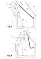
figure 4 illustre une phase intermédiaire du mouvement du mécanisme d'enroulement/déroulement entre sa première position escamotée et sa deuxième position déployée. - La
figure 5 montre un deuxième mode de réalisation d'un dispositif de recouvrement de bassin selon l'invention avec un mécanisme d'enroulement/déroulement disposé dans sa première position escamotée. - La
figure 6 montre un deuxième mode de réalisation d'un dispositif de recouvrement de bassin selon l'invention avec un mécanisme d'enroulement/déroulement disposé entre sa première position escamotée et sa deuxième position déployée.
- The
figure 1 shows a general perspective view of a first embodiment of a recovery device according to the invention. - The
figure 2 shows a first embodiment of a basin covering device according to the invention with a winding / unwinding mechanism arranged in its first retracted position. - The
figure 3 shows a first embodiment of a basin covering device according to the invention with a winding / unwinding mechanism arranged in its second deployed position. - The
figure 4 illustrates an intermediate phase of the movement of the winding / unwinding mechanism between its first retracted position and its second deployed position. - The
figure 5 shows a second embodiment of a basin covering device according to the invention with a winding / unwinding mechanism arranged in its first retracted position. - The
figure 6 shows a second embodiment of a basin covering device according to the invention with a winding / unwinding mechanism disposed between its first retracted position and its second deployed position.
Comme illustré dans un premier mode de réalisation présenté aux
Ce dispositif de recouvrement 1 comprend un mécanisme d'enroulement/déroulement 4 d'une couverture 2, et un dispositif d'escamotage/déploiement 15 du mécanisme d'enroulement/déroulement 4 dans le ou du compartiment 3.This covering
Le mécanisme d'enroulement/déroulement 4 présente une forme tubulaire allongée de manière à faciliter l'enroulement et le déroulement de la couverture 2 autour de celui-ci.The winding /
La couverture 2 est reliée par des sangles souples au mécanisme d'enroulement/déroulement 4.The
La couverture 2 peut être réalisée en matériau souple, tel une bâche ou bien réalisé sous forme d'un tablier à lames.The
Le tablier à lame est particulièrement avantageux car il permet d'être adapté à différentes formes de bassins.The apron blade is particularly advantageous because it can be adapted to different forms of pools.
En outre, le compartiment 3 peut être recouvert d'une trappe 8 amovible.In addition, the
Le dispositif d'escamotage/déploiement 15 est agencé pour entrainer le mécanisme d'enroulement/déroulement 4 entre une première position escamotée P1 illustrée à la
Le dispositif d'escamotage/déploiement 15 comprend un ensemble 10 de bras articulés reliant le mécanisme d'enroulement/déroulement 4 à un point fixe du compartiment 3.The retraction /
Dans le premier mode de réalisation présenté, l'ensemble 10 de bras articulés comprend une paire de premier bras articulés 11 a, 11 b et une paire de deuxième bras articulés 12a, 12b.In the first embodiment shown, the articulated arm assembly comprises a pair of first articulated
Chaque premier bras articulé 11a, 11b est relié solidairement sur une première de ses deux extrémités à une des deux extrémités du mécanisme d'enroulement/déroulement 4.Each first articulated
En effet, le mécanisme d'enroulement/déroulement 4 comprend un moteur tubulaire. La partie du mécanisme d'enroulement/déroulement 4 reliée à la couverture 2 ne peut donc tourner autour de l'axe longitudinal de rotation du mécanisme d'enroulement/déroulement 4 que lors de l'actionnement du moteur tubulaire ou bien lors d'un éventuel débrayage du moteur.Indeed, the winding /
Par conséquent, le mécanisme d'enroulement/déroulement 4 est bien solidaire en rotation de chaque premier bras articulé 11a, 11b entre la première position escamotée P1 et la deuxième position déployée P2 du mécanisme d'enroulement/déroulement 4.Therefore, the winding /
Ainsi, la rotation des premiers bras articulé 11a, 11 b entraine dans cette même rotation l'axe du mécanisme d'enroulement/déroulement 4.Thus, the rotation of the first articulated
Chaque deuxième bras articulé 12a, 12b est respectivement relié d'une part sur une première de ses deux extrémités à la deuxième extrémité d'un des deux premiers bras articulés 11a, 11b par une première liaison pivot 13a, 13b et d'autre part sur une deuxième de ses deux extrémités à un point fixe du compartiment 3 par une deuxième liaison pivot 14a, 14b.Each second articulated
En outre, le dispositif de recouvrement 1 comprend un tube de renfort 5 reliant les deux deuxième bras articulé 12a, 12b sensiblement à leur mi-hauteur, et un vérin hydraulique 6 relié d'une part à un point fixe du compartiment 3 sur lequel il prend appui et d'autre part au tube de renfort 5.In addition, the
Bien entendu, la présente invention n'est pas limitée à un nombre ou à un type de moyen d'actionnement particulier.Of course, the present invention is not limited to any number or type of particular actuating means.
C'est ainsi que dans un deuxième mode de réalisation illustré aux
Dans ce mode de réalisation, la présence du châssis 30 permet de rigidifier le dispositif de recouvrement 1 et de supprimer le tube de renfort 5.In this embodiment, the presence of the
L'actionnement du ou des vérins hydrauliques 6, 6a, 6b permet la mise en mouvement du dispositif d'escamotage/déploiement 15 de manière à entrainer le mécanisme d'enroulement/déroulement 4 entre sa première position escamotée P1 et sa deuxième position déployée P2.The actuation of the hydraulic cylinder (s) 6, 6a, 6b enables the retraction /
Une fois que le mécanisme d'enroulement/déroulement 4 a atteint sa deuxième position déployée P2, le mécanisme 4 peut dérouler entièrement la couverture 2.Once the winding /
Le mécanisme d'enroulement/déroulement 4 qui reste relié à la couverture 2 par les sangles souples peut ensuite être ramené dans sa première position escamotée P1 dans le compartiment 3 alors que le bassin reste couvert par la couverture 2.The winding /
Le compartiment 3 peut alors être refermé par la trappe 8.The
Dans le premier mode de réalisation présenté, le mouvement du mécanisme d'enroulement/déroulement 4 entre sa première position escamotée P1 et sa deuxième position déployée P2 présente plusieurs phases de fonctionnement distinctes ϕ1, ϕi, ϕ2.In the first embodiment shown, the movement of the winding /
La première phase de fonctionnement ϕ1 débute ou respectivement se termine à la première position P1 escamotée illustrée à la
La deuxième phase de fonctionnement ϕ2 se termine ou respectivement débute à la deuxième position P2 déployée illustrée à la
La phase intermédiaire de fonctionnement ϕi survient entre la première phase de fonctionnement ϕ1 et la deuxième phase de fonctionnement ϕ2.The intermediate operating phase φi occurs between the first operating phase φ1 and the second operating phase φ2.
Au cours de cette phase intermédiaire de fonctionnement ϕi le mécanisme d'enroulement/déroulement 4 est en suspension, c'est-à-dire que les forces de réaction appliquées au niveau des liaisons pivots 13a, 13b ne comprennent qu'une composante verticale dans une position d'équilibre, et éventuellement une composante horizontale oscillant autour d'une valeur nulle dans une position de déséquilibre, en réaction au seul le poids du mécanisme d'enroulement/déroulement 4 et dans une moindre mesure au poids des premiers bras articulés 11 a, 11 b.During this intermediate operating phase φi the winding /
La suspension du mécanisme d'enroulement/déroulement 4 tend donc à annuler le moment de la force s'appliquant au niveau de ces mêmes liaisons pivots 13a, 13b.The suspension of the winding /
Ces différentes phases de fonctionnement ϕ1, ϕi, ϕ2 se distinguent de part l'action du dispositif d'escamotage/déploiement 15 sur le positionnement du mécanisme d'enroulement/déroulement 4.These different operating phases φ1, φi, φ2 are distinguished by the action of the retraction /
Afin de réaliser de tels positionnements, le dispositif d'escamotage/déploiement 15 comprend un ensemble de moyens de positionnement 20 du mouvement du mécanisme d'enroulement/déroulement 4 entre sa première position escamotée P1 et sa deuxième position déployée P2.In order to perform such positioning, the
Ainsi, dans le premier mode de réalisation présenté les moyens de positionnement 20 comportent une paire de premiers moyens de positionnement 21 a, 21 b matérialisés par des butées 21 a, 21 b.Thus, in the first embodiment shown the positioning means 20 comprise a pair of first positioning means 21a, 21b materialized by
Chaque butée 21 a, 21 b est respectivement fixée à un des deux premier bras articulés 11a, 11b à proximité de l'extrémité du premier bras articulés 11 a, 11 b sur laquelle est solidarisé le mécanisme d'enroulement/déroulement 4.Each
Ces butées 21a, 21b présentent une forme longiforme qui s'étend sensiblement en direction du bassin 7 et transversalement à une direction générale des premiers bras articulés 11a, 11 b.These
Chacune de ces deux butées 21 a, 21 b agencée pour limiter le mouvement de rotation d'un des deux premier bras articulés 11 a, 11 b autour de la première liaison pivot 13a, 13b au cours de la première phase de fonctionnement ϕ1 du mouvement du mécanisme d'enroulement/déroulement 4.Each of these two
A cet effet, chacune de ces butées 21 a, 21 b comprend une partie sur son extrémité libre faisant saillie en direction de l'autre butée 21 a, 21 b.For this purpose, each of these
Cette partie d'extrémité en saillie est agencée pour buter contre l'un des deux deuxième bras articulés 12a ,12b à un instant donné lors de l'escamotage du mécanisme d'enroulement/déroulement 4.This projecting end portion is arranged to abut against one of the two second articulated
Cet instant défini la limite entre la première phase de fonctionnement ϕ1 et la phase intermédiaire de fonctionnement ϕi.This instant defines the limit between the first phase of operation φ1 and the intermediate phase of operation φi.
Ainsi, au cours de la première phase de fonctionnement ϕ1 les butées 21 a, 21 b sont respectivement au contact des deux deuxième bras articulés 12a, 12b.Thus, during the first phase of operation φ1 the
Ces butées 21 a, 21 b permettent de reporter une partie de l'action du poids du mécanisme d'enroulement/déroulement 4 sur les points de contact avec les deux deuxièmes bras articulés 12a, 12b de manière à soulager les premières liaisons pivots 13a, 13b.These
Comme illustré à la
Un tel angle permet de réduire l'encombrement du dispositif d'escamotage/déploiement 15 et du mécanisme d'enroulement/déroulement 4 dans le compartiment 3 et évite un éventuel mouillage du mécanisme d'enroulement/déroulement 4 dans le fond du compartiment 3.Such an angle makes it possible to reduce the bulk of the
En outre, dans le premier mode de réalisation présenté les moyens de positionnement 20 comportent également une paire de deuxièmes moyens de positionnement 22a, 22b matérialisés par des bras de levier.In addition, in the first embodiment shown, the positioning means 20 also comprise a pair of second positioning means 22a, 22b embodied by lever arms.
Chaque bras de levier 22a, 22b est respectivement fixé à un des deux premier bras articulés 11 a, 11 b à proximité de l'extrémité du premier bras articulés 11 a, 11 b sur laquelle agit la première liaison pivot 13a, 13b.Each
Ces bras de levier 22a, 22b présentent une forme longiforme qui s'étend sensiblement en direction opposée au bassin 7 et transversalement à une direction générale des premiers bras articulés 11 a, 11 b.These
Chaque bras de levier 22a, 22b comprend sur son extrémité libre un orifice sur lequel est accrochée une première extrémité d'une chaîne 9a, 9b.Each
La deuxième extrémité de cette chaîne 9a, 9b est reliée à un point fixe du compartiment 3.The second end of this
Ces bras de levier 22a, 22b associés à leur chaîne 9a, 9b respectives sont agencés agencé pour accroitre le mouvement de rotation de l'au moins un premier bras articulé 11a, 11 b autour de la première liaison pivot 13a, 13b en direction du bassin en avant de la première liaison pivot 13a, 13b au cours de la phase finale de déploiement, et freiner le mouvement de rotation de l'au moins un premier bras articulé 11a, 11b autour de la première liaison pivot 13a, 13b vers une direction opposée au bassin au cours de la phase initiale de repli.These
L'écart angulaire entre les premier bras articulés 11 a, 11 b et les deuxième bras articulés 12a, 12b est ainsi augmenté au cours de la phase finale de déploiement.The angular difference between the first articulated
Ces bras de levier 22a, 22b sont donc entrainés en rotation à un instant donné lors du déploiement du mécanisme d'enroulement/déroulement 4.These
Cet instant défini la limite entre la deuxième phase de fonctionnement ϕ2 et la phase intermédiaire de fonctionnement ϕi.This instant defines the limit between the second operating phase φ2 and the intermediate operating phase φi.
Cet instant correspond à la tension des chaînes 9a, 9b lors du déploiement du mécanisme d'enroulement/déroulement 4.This instant corresponds to the tension of the
Selon une variante, ces chaînes 9a, 9b peuvent être remplacées par des vérins.According to one variant, these
Comme illustré à la
Dans le premier mode de réalisation présenté, l'augmentation de l'écart angulaire permet de placer le mécanisme d'enroulement/déroulement 4 à la verticale du bassin 7 dans sa deuxième position déployée de manière à ce que lors du déroulement de la couverture 2, celle-ci puisse atteindre directement par gravité l'eau du bassin 7, et cela même si le bassin est équipé de margelles imposant au mécanisme d'enroulement/déroulement 4 d'être plus avancé encore.In the first embodiment presented, the increase in the angular difference makes it possible to place the winding /
Cela est particulièrement utile lors de l'utilisation d'une couverture 2 du type tablier à lames, ces lames ayant la capacité de flotter et de se déplacer à la surface de l'eau.This is particularly useful when using a
Ainsi, au cours de la phase intermédiaire de fonctionnement ϕi les butées 21 a, 21 b ne sont pas au contact des deuxièmes bras articulés 12a, 12b et les bras de levier 22a, 22b ne sont pas actionnés par la mise en tension des chaînes 9a, 9b.Thus, during the intermediate operating phase φi the
Par conséquent, au cours de la phase intermédiaire de fonctionnement ϕi le mécanisme d'enroulement/déroulement 4 est simplement suspendu par les premières liaisons pivots 13a, 13b à l'extrémité des premiers bras articulés 11a, 11 b.Consequently, during the intermediate operating phase φi the winding /
Comme illustré à la
Enfin, l'inertie du mécanisme d'enroulement/déroulement 4 peut induire un mouvement pendulaire ou de balancier au mécanisme d'enroulement/déroulement 4 lors de son déplacement entre sa première position escamotée P1 et sa deuxième position déployée P2.Finally, the inertia of the winding /
Cependant, ce mouvement pendulaire peut efficacement être réduit en utilisant des dispositifs amortisseurs connus de l'homme du métier.However, this pendulum movement can be effectively reduced by using damping devices known to those skilled in the art.
Dans le deuxième mode de réalisation illustré aux
Chacune de ces chaines 21 a', 21 b' est respectivement reliée d'une part à l'un des deux premiers bras articulés 11a, 11 b et d'autre part à l'un des deux deuxièmes bras articulés 12a, 12b.Each of these
Comme illustré à la
Comme illustré à la
Dans ce même deuxième mode de réalisation, le dispositif de recouvrement 1 comprend des flasques souples 31 a, 31 b disposés sur les premiers bras articulés 11 a, 11 b destinés à prévenir le cisaillement d'un élément qui pourrait être disposé entre les premiers bras articulés 11 a, 11 b et les deuxièmes bras articulés 12a, 12b.In this same second embodiment, the
Par ailleurs, selon une variante de l'invention, le dispositif d'escamotage/déploiement 15 peut être équipé d'un système comprenant des galets au niveau des premières liaisons pivots13a, 13b permettant de soulever la trappe 8 du compartiment 3 en même temps que le déploiement du mécanisme d'enroulement/déroulement 4 du compartiment 3.Furthermore, according to one variant of the invention, the retraction /
Claims (10)
ledit dispositif d'escamotage/déploiement (4) étant agencé pour entrainer le mécanisme d'enroulement/déroulement (4) entre une première position escamotée (P1) dans laquelle le mécanisme d'enroulement/déroulement (4) de la couverture (2) est replié à l'intérieur du compartiment (3) et une deuxième position déployée (P2) dans laquelle le mécanisme d'enroulement/déroulement (4) de la couverture (2) est disposé à l'extérieur du compartiment (3),
ledit dispositif de recouvrement (1) de bassin (7) étant caractérisé en ce que le dispositif d'escamotage/déploiement (4) est agencé de telle sorte que le mouvement du mécanisme d'enroulement/déroulement (4) entre sa première position escamotée (P1) et sa deuxième position déployée (P2) présente au moins une phase de fonctionnement dite intermédiaire (ϕi) au cours de laquelle le mécanisme d'enroulement/déroulement (4) est en suspension sur le dispositif d'escamotage/déploiement (15).
said retraction / deployment device (4) being arranged to drive the winding / unwinding mechanism (4) between a first retracted position (P1) in which the winding / unwinding mechanism (4) of the cover (2) is folded inside the compartment (3) and a second extended position (P2) in which the winding / unwinding mechanism (4) of the cover (2) is arranged outside the compartment (3),
said basin covering device (1) being characterized in that the retraction / deployment device (4) is arranged such that the movement of the winding / unwinding mechanism (4) between its first retracted position (P1) and its second deployed position (P2) has at least one so-called intermediate operating phase (φi) during which the winding / unwinding mechanism (4) is in suspension on the retraction / deployment device (15). ).
le mécanisme d'enroulement/déroulement (4) au cours de la phase de fonctionnement dite intermédiaire (ϕi) étant suspendu par la première liaison pivot (13a, 13b) à l'au moins un deuxième bras articulé (12a, 12b) par l'intermédiaire de l'au moins un premier bras articulé (11 a, 11 b).
the winding / unwinding mechanism (4) during the so-called intermediate operating phase (φi) being suspended by the first pivot connection (13a, 13b) to the at least one second articulated arm (12a, 12b) by the intermediate of the at least one first articulated arm (11a, 11b).
Applications Claiming Priority (1)
| Application Number | Priority Date | Filing Date | Title |
|---|---|---|---|
| FR1360020A FR3011867B1 (en) | 2013-10-15 | 2013-10-15 | BASIN RECOVERY DEVICE |
Publications (2)
| Publication Number | Publication Date |
|---|---|
| EP2865824A2 true EP2865824A2 (en) | 2015-04-29 |
| EP2865824A3 EP2865824A3 (en) | 2015-12-09 |
Family
ID=49713329
Family Applications (1)
| Application Number | Title | Priority Date | Filing Date |
|---|---|---|---|
| EP14188772.9A Withdrawn EP2865824A3 (en) | 2013-10-15 | 2014-10-14 | Device for covering a pool |
Country Status (2)
| Country | Link |
|---|---|
| EP (1) | EP2865824A3 (en) |
| FR (1) | FR3011867B1 (en) |
Cited By (1)
| Publication number | Priority date | Publication date | Assignee | Title |
|---|---|---|---|---|
| FR3066774A1 (en) * | 2017-05-29 | 2018-11-30 | Sarl P.P.E.L. Paysage Piscine Environnement Loisirs | SYSTEM FOR STORING A PROTECTIVE PART FOR A SWIMMING POOL IN A CHEST WITH AN ARTICULATED COVER |
Citations (4)
| Publication number | Priority date | Publication date | Assignee | Title |
|---|---|---|---|---|
| DE2938496A1 (en) | 1978-10-17 | 1980-04-24 | Glatz Ag | COVER DEVICE FOR A POOL FILLED WITH LIQUID |
| DE3142873A1 (en) | 1981-10-29 | 1983-05-11 | Robert 5060 Bergisch Gladbach Granderath | Device for covering liquid-containing basins |
| DE4109584A1 (en) | 1990-04-04 | 1991-10-10 | Aquamarq Ag | Cover for swimming pool - is wound on to roll mounted on ends of hydraulically actuated arms |
| EP2157261A1 (en) | 2008-08-21 | 2010-02-24 | Cr2D | Covering device for a pool, such as a swimming pool. |
-
2013
- 2013-10-15 FR FR1360020A patent/FR3011867B1/en active Active
-
2014
- 2014-10-14 EP EP14188772.9A patent/EP2865824A3/en not_active Withdrawn
Patent Citations (4)
| Publication number | Priority date | Publication date | Assignee | Title |
|---|---|---|---|---|
| DE2938496A1 (en) | 1978-10-17 | 1980-04-24 | Glatz Ag | COVER DEVICE FOR A POOL FILLED WITH LIQUID |
| DE3142873A1 (en) | 1981-10-29 | 1983-05-11 | Robert 5060 Bergisch Gladbach Granderath | Device for covering liquid-containing basins |
| DE4109584A1 (en) | 1990-04-04 | 1991-10-10 | Aquamarq Ag | Cover for swimming pool - is wound on to roll mounted on ends of hydraulically actuated arms |
| EP2157261A1 (en) | 2008-08-21 | 2010-02-24 | Cr2D | Covering device for a pool, such as a swimming pool. |
Cited By (1)
| Publication number | Priority date | Publication date | Assignee | Title |
|---|---|---|---|---|
| FR3066774A1 (en) * | 2017-05-29 | 2018-11-30 | Sarl P.P.E.L. Paysage Piscine Environnement Loisirs | SYSTEM FOR STORING A PROTECTIVE PART FOR A SWIMMING POOL IN A CHEST WITH AN ARTICULATED COVER |
Also Published As
| Publication number | Publication date |
|---|---|
| EP2865824A3 (en) | 2015-12-09 |
| FR3011867B1 (en) | 2016-03-04 |
| FR3011867A1 (en) | 2015-04-17 |
Similar Documents
| Publication | Publication Date | Title |
|---|---|---|
| CA2799688C (en) | Device for unlocking a landing gear in a deployed position and a landing gear comprising one such device | |
| EP3347526B1 (en) | Drilling machine | |
| FR2645089A1 (en) | LEVER PLATFORM FOR TRUCK | |
| EP3347527B1 (en) | Machine for making a diaphragm wall | |
| EP0069611B1 (en) | Lifting device for a platform mounted on a motor vehicle | |
| EP0280626B1 (en) | System for unfolding and placing a bridge from a vehicle such as a bridge-laying tank for passing an obstacle | |
| EP0041016B1 (en) | Automatically retractable stowing shelf | |
| FR2527187A1 (en) | FOLDABLE RAMP, PARTICULARLY FOR ROAD TRANSPORT | |
| EP2865824A2 (en) | Device for covering a pool | |
| EP2868842B1 (en) | Device for locking a swimming-pool cover in an extended position | |
| EP3816091A1 (en) | Hammerhead tower crane with automatic folding and unfolding | |
| EP0233090B1 (en) | Glass container | |
| EP3225582B1 (en) | Folding structure making up a tower crane | |
| FR2493818A1 (en) | SELF-RACING CRANE EQUIPPED WITH DEPLOYABLE STABILIZING SUPPORTS AND MOBILE FORCE LEGS VERTICALLY ASSOCIATED WITH THEM, AND DEPLOYABLE SUPPORT SO REALIZED | |
| FR2684341A1 (en) | Device for raising or withdrawing a ladder or the like onto or from a roof rack of a vehicle | |
| FR2930536A1 (en) | Hoisting engine for being mounted on transport truck in e.g. construction site, has mast and deflection comprising retraction unit for placing mast and deflection from deployed position to retracted position and vice versa | |
| EP0775605B1 (en) | Roller-blind with deployment mechanism having swinging links | |
| FR2800704A1 (en) | Aircraft landing gear for underwing use has stiffening actuator to allow flexibility except in deployment phase | |
| FR2795696A1 (en) | Stabilizing apparatus for load carrier has leg which can be folded on top of load carrier or unfolded and in contact with the ground | |
| FR2908704A1 (en) | BACHING DEVICE | |
| WO2008000923A1 (en) | Anti-slosh device for flexible tank | |
| FR3066485A1 (en) | SYSTEM FOR IMMERING AN OBJECT FROM A FLOATING OR NON-FLOATING PLATFORM | |
| BE571844A (en) | ||
| FR2811705A1 (en) | ROLLER SHUTTER COMPRISING MEANS FOR LOCKING THE WINDING SHAFT OF ITS APRON | |
| CH286392A (en) | Scraper device for cleaning a hydraulic installation grid. |
Legal Events
| Date | Code | Title | Description |
|---|---|---|---|
| PUAI | Public reference made under article 153(3) epc to a published international application that has entered the european phase |
Free format text: ORIGINAL CODE: 0009012 |
|
| 17P | Request for examination filed |
Effective date: 20141014 |
|
| AK | Designated contracting states |
Kind code of ref document: A2 Designated state(s): AL AT BE BG CH CY CZ DE DK EE ES FI FR GB GR HR HU IE IS IT LI LT LU LV MC MK MT NL NO PL PT RO RS SE SI SK SM TR |
|
| AX | Request for extension of the european patent |
Extension state: BA ME |
|
| PUAL | Search report despatched |
Free format text: ORIGINAL CODE: 0009013 |
|
| AK | Designated contracting states |
Kind code of ref document: A3 Designated state(s): AL AT BE BG CH CY CZ DE DK EE ES FI FR GB GR HR HU IE IS IT LI LT LU LV MC MK MT NL NO PL PT RO RS SE SI SK SM TR |
|
| AX | Request for extension of the european patent |
Extension state: BA ME |
|
| RIC1 | Information provided on ipc code assigned before grant |
Ipc: E04H 4/10 20060101AFI20151105BHEP |
|
| R17P | Request for examination filed (corrected) |
Effective date: 20160603 |
|
| RBV | Designated contracting states (corrected) |
Designated state(s): AL AT BE BG CH CY CZ DE DK EE ES FI FR GB GR HR HU IE IS IT LI LT LU LV MC MK MT NL NO PL PT RO RS SE SI SK SM TR |
|
| 17Q | First examination report despatched |
Effective date: 20171214 |
|
| STAA | Information on the status of an ep patent application or granted ep patent |
Free format text: STATUS: THE APPLICATION IS DEEMED TO BE WITHDRAWN |
|
| 18D | Application deemed to be withdrawn |
Effective date: 20180425 |