EP2865437B1 - Filter element comprising a seal arrangement - Google Patents
Filter element comprising a seal arrangement Download PDFInfo
- Publication number
- EP2865437B1 EP2865437B1 EP14196909.7A EP14196909A EP2865437B1 EP 2865437 B1 EP2865437 B1 EP 2865437B1 EP 14196909 A EP14196909 A EP 14196909A EP 2865437 B1 EP2865437 B1 EP 2865437B1
- Authority
- EP
- European Patent Office
- Prior art keywords
- media
- media pack
- filter element
- seal
- air cleaner
- Prior art date
- Legal status (The legal status is an assumption and is not a legal conclusion. Google has not performed a legal analysis and makes no representation as to the accuracy of the status listed.)
- Active
Links
- 238000000034 method Methods 0.000 claims description 43
- 230000008569 process Effects 0.000 claims description 27
- 238000000465 moulding Methods 0.000 claims description 19
- 238000007789 sealing Methods 0.000 claims description 15
- 238000001914 filtration Methods 0.000 claims description 5
- 239000003566 sealing material Substances 0.000 claims 1
- 239000000463 material Substances 0.000 description 47
- 239000011324 bead Substances 0.000 description 35
- 238000007906 compression Methods 0.000 description 24
- 230000006835 compression Effects 0.000 description 24
- 229920005989 resin Polymers 0.000 description 24
- 239000011347 resin Substances 0.000 description 24
- 239000000565 sealant Substances 0.000 description 20
- 238000010276 construction Methods 0.000 description 15
- 238000004804 winding Methods 0.000 description 10
- 238000012360 testing method Methods 0.000 description 8
- 239000000356 contaminant Substances 0.000 description 7
- 239000000853 adhesive Substances 0.000 description 6
- 230000001070 adhesive effect Effects 0.000 description 6
- 230000015572 biosynthetic process Effects 0.000 description 6
- 239000012530 fluid Substances 0.000 description 6
- 238000005755 formation reaction Methods 0.000 description 6
- 238000004519 manufacturing process Methods 0.000 description 6
- 229920002635 polyurethane Polymers 0.000 description 6
- 239000004814 polyurethane Substances 0.000 description 6
- JOYRKODLDBILNP-UHFFFAOYSA-N Ethyl urethane Chemical compound CCOC(N)=O JOYRKODLDBILNP-UHFFFAOYSA-N 0.000 description 5
- XLYOFNOQVPJJNP-UHFFFAOYSA-N water Substances O XLYOFNOQVPJJNP-UHFFFAOYSA-N 0.000 description 5
- 239000012943 hotmelt Substances 0.000 description 4
- 238000009434 installation Methods 0.000 description 4
- 239000012948 isocyanate Substances 0.000 description 4
- 150000002513 isocyanates Chemical class 0.000 description 4
- 239000000203 mixture Substances 0.000 description 4
- 230000002093 peripheral effect Effects 0.000 description 4
- 239000011148 porous material Substances 0.000 description 4
- 238000012552 review Methods 0.000 description 4
- 238000012512 characterization method Methods 0.000 description 3
- 238000006073 displacement reaction Methods 0.000 description 3
- 239000002657 fibrous material Substances 0.000 description 3
- 239000011521 glass Substances 0.000 description 3
- 238000012986 modification Methods 0.000 description 3
- 230000004048 modification Effects 0.000 description 3
- 239000000047 product Substances 0.000 description 3
- MLZKFBZEYADEIN-UHFFFAOYSA-N 5-chloro-4-[(3-ethoxy-4-methoxyphenyl)methylamino]-1h-pyridazin-6-one Chemical compound C1=C(OC)C(OCC)=CC(CNC2=C(C(=O)NN=C2)Cl)=C1 MLZKFBZEYADEIN-UHFFFAOYSA-N 0.000 description 2
- 229920003043 Cellulose fiber Polymers 0.000 description 2
- 239000004677 Nylon Substances 0.000 description 2
- 230000003466 anti-cipated effect Effects 0.000 description 2
- 238000013459 approach Methods 0.000 description 2
- 230000008901 benefit Effects 0.000 description 2
- 230000008859 change Effects 0.000 description 2
- 238000002485 combustion reaction Methods 0.000 description 2
- 239000006260 foam Substances 0.000 description 2
- 238000009472 formulation Methods 0.000 description 2
- 239000012092 media component Substances 0.000 description 2
- 229920001778 nylon Polymers 0.000 description 2
- 229920000642 polymer Polymers 0.000 description 2
- 238000002360 preparation method Methods 0.000 description 2
- 229920002994 synthetic fiber Polymers 0.000 description 2
- 239000012209 synthetic fiber Substances 0.000 description 2
- 238000011144 upstream manufacturing Methods 0.000 description 2
- 239000004604 Blowing Agent Substances 0.000 description 1
- 239000004721 Polyphenylene oxide Substances 0.000 description 1
- 238000010521 absorption reaction Methods 0.000 description 1
- 230000032683 aging Effects 0.000 description 1
- 150000001412 amines Chemical class 0.000 description 1
- 230000000712 assembly Effects 0.000 description 1
- 238000000429 assembly Methods 0.000 description 1
- 238000005452 bending Methods 0.000 description 1
- 238000009835 boiling Methods 0.000 description 1
- 239000006229 carbon black Substances 0.000 description 1
- 239000003054 catalyst Substances 0.000 description 1
- 239000007795 chemical reaction product Substances 0.000 description 1
- 239000011248 coating agent Substances 0.000 description 1
- 238000000576 coating method Methods 0.000 description 1
- 238000013036 cure process Methods 0.000 description 1
- 150000002009 diols Chemical class 0.000 description 1
- 239000000428 dust Substances 0.000 description 1
- 239000000975 dye Substances 0.000 description 1
- 238000011156 evaluation Methods 0.000 description 1
- 239000000835 fiber Substances 0.000 description 1
- 239000012467 final product Substances 0.000 description 1
- 238000005187 foaming Methods 0.000 description 1
- 239000000446 fuel Substances 0.000 description 1
- 230000009477 glass transition Effects 0.000 description 1
- 230000005484 gravity Effects 0.000 description 1
- 238000010438 heat treatment Methods 0.000 description 1
- 125000002887 hydroxy group Chemical group [H]O* 0.000 description 1
- 238000012994 industrial processing Methods 0.000 description 1
- 238000001746 injection moulding Methods 0.000 description 1
- 239000007788 liquid Substances 0.000 description 1
- 238000012423 maintenance Methods 0.000 description 1
- 238000005065 mining Methods 0.000 description 1
- 239000013518 molded foam Substances 0.000 description 1
- 239000002245 particle Substances 0.000 description 1
- 230000000704 physical effect Effects 0.000 description 1
- 239000000049 pigment Substances 0.000 description 1
- 229920000570 polyether Polymers 0.000 description 1
- 229920005862 polyol Polymers 0.000 description 1
- 150000003077 polyols Chemical class 0.000 description 1
- 229920005749 polyurethane resin Polymers 0.000 description 1
- 238000010248 power generation Methods 0.000 description 1
- 230000009467 reduction Effects 0.000 description 1
- 230000000630 rising effect Effects 0.000 description 1
- 239000004094 surface-active agent Substances 0.000 description 1
- 229920002803 thermoplastic polyurethane Polymers 0.000 description 1
- 230000007704 transition Effects 0.000 description 1
- 150000004072 triols Chemical class 0.000 description 1
- 238000003466 welding Methods 0.000 description 1
Images


Classifications
-
- B—PERFORMING OPERATIONS; TRANSPORTING
- B01—PHYSICAL OR CHEMICAL PROCESSES OR APPARATUS IN GENERAL
- B01D—SEPARATION
- B01D46/00—Filters or filtering processes specially modified for separating dispersed particles from gases or vapours
- B01D46/52—Particle separators, e.g. dust precipitators, using filters embodying folded corrugated or wound sheet material
- B01D46/521—Particle separators, e.g. dust precipitators, using filters embodying folded corrugated or wound sheet material using folded, pleated material
- B01D46/525—Particle separators, e.g. dust precipitators, using filters embodying folded corrugated or wound sheet material using folded, pleated material which comprises flutes
- B01D46/527—Particle separators, e.g. dust precipitators, using filters embodying folded corrugated or wound sheet material using folded, pleated material which comprises flutes in wound arrangement
-
- B—PERFORMING OPERATIONS; TRANSPORTING
- B01—PHYSICAL OR CHEMICAL PROCESSES OR APPARATUS IN GENERAL
- B01D—SEPARATION
- B01D46/00—Filters or filtering processes specially modified for separating dispersed particles from gases or vapours
- B01D46/52—Particle separators, e.g. dust precipitators, using filters embodying folded corrugated or wound sheet material
-
- B—PERFORMING OPERATIONS; TRANSPORTING
- B01—PHYSICAL OR CHEMICAL PROCESSES OR APPARATUS IN GENERAL
- B01D—SEPARATION
- B01D46/00—Filters or filtering processes specially modified for separating dispersed particles from gases or vapours
-
- B—PERFORMING OPERATIONS; TRANSPORTING
- B01—PHYSICAL OR CHEMICAL PROCESSES OR APPARATUS IN GENERAL
- B01D—SEPARATION
- B01D46/00—Filters or filtering processes specially modified for separating dispersed particles from gases or vapours
- B01D46/0001—Making filtering elements
-
- B—PERFORMING OPERATIONS; TRANSPORTING
- B01—PHYSICAL OR CHEMICAL PROCESSES OR APPARATUS IN GENERAL
- B01D—SEPARATION
- B01D46/00—Filters or filtering processes specially modified for separating dispersed particles from gases or vapours
- B01D46/0002—Casings; Housings; Frame constructions
- B01D46/0004—Details of removable closures, lids, caps or filter heads
-
- B—PERFORMING OPERATIONS; TRANSPORTING
- B01—PHYSICAL OR CHEMICAL PROCESSES OR APPARATUS IN GENERAL
- B01D—SEPARATION
- B01D46/00—Filters or filtering processes specially modified for separating dispersed particles from gases or vapours
- B01D46/10—Particle separators, e.g. dust precipitators, using filter plates, sheets or pads having plane surfaces
-
- B—PERFORMING OPERATIONS; TRANSPORTING
- B01—PHYSICAL OR CHEMICAL PROCESSES OR APPARATUS IN GENERAL
- B01D—SEPARATION
- B01D46/00—Filters or filtering processes specially modified for separating dispersed particles from gases or vapours
- B01D46/52—Particle separators, e.g. dust precipitators, using filters embodying folded corrugated or wound sheet material
- B01D46/521—Particle separators, e.g. dust precipitators, using filters embodying folded corrugated or wound sheet material using folded, pleated material
- B01D46/525—Particle separators, e.g. dust precipitators, using filters embodying folded corrugated or wound sheet material using folded, pleated material which comprises flutes
-
- B—PERFORMING OPERATIONS; TRANSPORTING
- B01—PHYSICAL OR CHEMICAL PROCESSES OR APPARATUS IN GENERAL
- B01D—SEPARATION
- B01D46/00—Filters or filtering processes specially modified for separating dispersed particles from gases or vapours
- B01D46/52—Particle separators, e.g. dust precipitators, using filters embodying folded corrugated or wound sheet material
- B01D46/528—Particle separators, e.g. dust precipitators, using filters embodying folded corrugated or wound sheet material using wound sheets
-
- F—MECHANICAL ENGINEERING; LIGHTING; HEATING; WEAPONS; BLASTING
- F02—COMBUSTION ENGINES; HOT-GAS OR COMBUSTION-PRODUCT ENGINE PLANTS
- F02M—SUPPLYING COMBUSTION ENGINES IN GENERAL WITH COMBUSTIBLE MIXTURES OR CONSTITUENTS THEREOF
- F02M35/00—Combustion-air cleaners, air intakes, intake silencers, or induction systems specially adapted for, or arranged on, internal-combustion engines
- F02M35/02—Air cleaners
- F02M35/024—Air cleaners using filters, e.g. moistened
- F02M35/02475—Air cleaners using filters, e.g. moistened characterised by the shape of the filter element
- F02M35/02483—Cylindrical, conical, oval, spherical or the like filter elements; wounded filter elements
-
- B—PERFORMING OPERATIONS; TRANSPORTING
- B01—PHYSICAL OR CHEMICAL PROCESSES OR APPARATUS IN GENERAL
- B01D—SEPARATION
- B01D2271/00—Sealings for filters specially adapted for separating dispersed particles from gases or vapours
- B01D2271/02—Gaskets, sealings
-
- B—PERFORMING OPERATIONS; TRANSPORTING
- B01—PHYSICAL OR CHEMICAL PROCESSES OR APPARATUS IN GENERAL
- B01D—SEPARATION
- B01D2271/00—Sealings for filters specially adapted for separating dispersed particles from gases or vapours
- B01D2271/02—Gaskets, sealings
- B01D2271/027—Radial sealings
-
- B—PERFORMING OPERATIONS; TRANSPORTING
- B01—PHYSICAL OR CHEMICAL PROCESSES OR APPARATUS IN GENERAL
- B01D—SEPARATION
- B01D2279/00—Filters adapted for separating dispersed particles from gases or vapours specially modified for specific uses
- B01D2279/60—Filters adapted for separating dispersed particles from gases or vapours specially modified for specific uses for the intake of internal combustion engines or turbines
-
- Y—GENERAL TAGGING OF NEW TECHNOLOGICAL DEVELOPMENTS; GENERAL TAGGING OF CROSS-SECTIONAL TECHNOLOGIES SPANNING OVER SEVERAL SECTIONS OF THE IPC; TECHNICAL SUBJECTS COVERED BY FORMER USPC CROSS-REFERENCE ART COLLECTIONS [XRACs] AND DIGESTS
- Y10—TECHNICAL SUBJECTS COVERED BY FORMER USPC
- Y10S—TECHNICAL SUBJECTS COVERED BY FORMER USPC CROSS-REFERENCE ART COLLECTIONS [XRACs] AND DIGESTS
- Y10S55/00—Gas separation
- Y10S55/30—Exhaust treatment
Definitions
- the present invention relates to air cleaners with removable and replaceable, i.e., serviceable, filter element or cartridge components.
- the invention described is particularly useful in air cleaners for use in filtering intake air for engines (used for example in: vehicles, construction, agricultural and mining equipment; and, generator systems).
- the invention specifically concerns seal arrangements provided on serviceable filter elements or cartridges, for such air cleaners.
- the invention also concerns methods of assembly and use.
- Air streams carry contaminant material therein.
- air flow streams to engines for motorized vehicles or for power generation equipment, construction equipment or other equipment, gas streams to gas turbine systems and air streams to various combustion furnaces carry particulate contaminant therein. It is preferred for such systems that the selected contaminant material be removed from (or have its level reduced in) the air or gas.
- a variety of air filter arrangements have been developed for contaminant reduction.
- a known filter element is for example disclosed in WO 00/32295 A2 and in WO 03/095068 A In general, however, continued improvements are sought.
- a filter element according to the present invention is defined in independent claim 1.
- a filter element or cartridge for use in air filtering.
- the filter element or cartridge comprises a media pack including opposite inlet and outlet ends.
- the media pack defines: a set of inlet flutes open at the inlet end of the media pack to passage of air to be filtered therein, the inlet flutes being closed preferably at a location within a distance of 10% of the total length of the inlet flutes from the outlet end of the media pack; and, a set of outlet flutes closed to passage of air to be filtered therein preferably at a distance within 10% of the total length of the inlet flutes from the inlet end of the media pack and open the passage of filtered air therefrom at the outlet end of the media pack.
- the element or cartridge further includes: a preform positioned adjacent a first one of the inlet and outlet ends of the media pack; and, an overmold formed of seal material having a first portion sealing at a joint or interface between the preform and a first end of the media pack at which the preform is positioned; and, a second portion oriented to form an air cleaner seal, between the filter element (or cartridge) and an air cleaner, when the filter element is installed for use.
- the first and second portions of the overmold are integral with one another, in a preferred, convenient, arrangement.
- the media pack is a coiled z-filter media arrangement; and, the overmold comprises foamed polyurethane.
- the media pack can have a variety of shapes and configurations. Two examples depicted are: an oval shape, for example having a racetrack perimeter or cross-sectional shape; and, a circular perimeter or cross-sectional shape. A variety of alternate shapes, are possible.
- the media of the elements comprises a first corrugated sheet of media attached to a second sheet of media (typically a flat media or nearly flat media) to form a single facer; and (b) in which the single facer combination is either wound or stacked, to create a media arrangement comprising a plurality of inlet flutes open at an inlet end face of the filter media and closed at or near (typically within 10% of the total length of the inlet flutes of) the outlet face of the media; and, a plurality of outlet flow flutes seal closed at or near the inlet face of the media (i.e., typically within 10% of the total length of the outlet flutes of the inlet face), and open at the outlet end face of the media.
- Such media arrangements are well known and are described for example in U.S. 5,820,646 ; 5,772,883 ; 5,902,364 ; 5,792,247 ; 6,190,432 and 6,350,291 .
- such media will sometimes be referred to as z-filter media; and, media packs formed from such media as z-filter media packs.
- a characteristic of such media packs, and the ones described herein is that they are closed to passage of unfiltered air through the packs, between the opposite end faces.
- the end seals of the flutes can be provided in a variety of ways, including through utilization of sealant beads; darting, folding or other arrangements for distorting the shape of the flute at the end and/or closing and sealing the flute ends; and through combinations thereof. Not all flutes need to be sealed closed in the same way.
- the particular approach to sealing is generally a matter of choice, not specifically related to the general principles described herein (except as indicated below) in connection with provision of seals between the serviceable filter element and a housing or housing component, in use.
- coiled and variants thereof, when used to refer to a media pack form from z-filter media, is meant to refer to a media pack formed by coiling a single combination strip of media or single facer, made from a strip of corrugated media secured to flat or nearly flat sheet (the combination being a single facer), in order to form the media pack.
- Such coiled media can be made in a variety of shapes including: round or cylindrical; oval, for example racetrack; square; or rectangular with rounded corners; and, they can even be configured in conical or similar arrangements. Examples of selected ones of these are described in U.S. 6,350,291 and U.S. provisional application Serial Number 60/467,521, filed May 2, 2003 .
- stacked arrangements generally refers to media packs that are not formed from a single combination strip of media that is coiled, but rather to media packs formed from a plurality of strips of media or single facer (corrugated media secured to flat or nearly flat media); the strips being secured to one another in a stack or block form. Stacked arrangements are described for example in U.S. 5,820,646 , at Fig. 3 .
- z-filter media pack arrangements as described, are used in serviceable filter elements (or cartridges), i.e., filter elements (or cartridges) that are removable and replaceable with respect to an air cleaner in which they are used.
- z-filter media packs are provided with sealing arrangements for engagement with portions of air cleaner parts such as a housing, in use.
- seals are referred to as “air cleaner seals” or “housing seals,” or by variants thereof.
- air cleaner seals A variety of such air cleaner seals are known.
- One type, involving an outside or outwardly directed radial seal, is described in U.S. 6,350,291 at Ref. #250, Fig. 5 .
- seals useable with z-pack media are axial pinch seals, as described for example in U.S. 6,348,085 ; 6,368,374 and U.S. Publication US 2002/0185007 A1 ; and, internally directed radial seals, as described for example in U.S. Provisional 60/457,255 filed March 25, 2003 at Fig. 12 .
- the reference numeral 1, Fig. 1 generally depicts a serviceable filter element (sometimes called a cartridge) according to the present disclosure.
- the filter element 1 depicted comprises a z-filter media pack 2 having an air cleaner seal arrangement 3 positioned thereon.
- air cleaner seal arrangement and variants thereof is generally meant to reference a seal arrangement 3 provided on a serviceable filter element 1 in such a manner that, when the filter element 1 is installed in an air cleaner for use, the seal arrangement 3 provides for an air seal with appropriate componentry or portions of air cleaner, typically an air cleaner housing.
- serviceable element in this context, is meant to refer to a filter element 1 which is removable and replaceable with respect to other portions of an air cleaner.
- the particular air cleaner seal arrangement 3 depicted comprises an outside radial seal member.
- outside radial seal member in this context, it is meant that the surface 6 which forms a seal with an air cleaner component, in use, is directed radially outwardly, rather than radially inwardly with respect to the portion of the serviceable filter element 1 on which it is mounted.
- the principles described herein could be applied with alternate orientations and types of seals, but the particular seal configuration characterized is a convenient, advantageous, example.
- inlet arrow 9 and exit arrow 10 air flow through the z-filter media pack 2 is shown by inlet arrow 9 and exit arrow 10. It is a characteristic of z-filter media packs, that air flow therethrough is generally such that the inlet flow arrow and exit flow arrow are generally parallel to one another. That is, the only turns the air needs to make in passage through the element 1 are minor turns in flow through media pack 2, since the air flow flutes are generally parallel to one another, and parallel to the direction of inlet and outlet flow. It is noted that an opposite direction of air flow to that shown by arrows 9 and 10 is possible, but this particular direction of air flow shown, in use, is advantageous. When constructed and oriented for use in this manner, the media pack 2 has an inlet end or flow face 15 and an opposite exit end or flow face 16.
- the inlet flow face 15 and exit flow face 16 are each substantially planar and are substantially parallel with one another. Although alternate arrangements are possible, the principles disclosed herein are particularly well considered for this application.
- Fig. 2 is a top plan view of filter element arrangement 1.
- the z-filter media 2 and seal arrangement 3 are provided with an oval outside perimeter shape, in this instance corresponding to two similar, opposite, curved ends 20, 21 spaced apart by two opposite, generally straight, sides, 22, 23.
- this specific oval configuration will generally be referred to as a "racetrack" shape.
- Racetrack shaped z-filter media pack elements are described in the prior art, for example, in U.S. 6,350,291 at Fig. 10 . It will be seen that many of the principles of the present disclosure can be applied in elements having media packs with alternate peripheral shapes, for example circular, as described herein below.
- oval shape would one in which the opposite sides are not straight, but are curved somewhat, with less curvature than the ends.
- Another shape which is possible is a shape which has two pairs of opposite, generally straight, sides which may or may not have a slight curvature to them, with four substantially curved corners.
- An example of this type of element is described in U.S. provisional application 60/457,255 , in Fig. 22 .
- the filter element 1 includes an optional end piece or skid skirt 30 thereon, at an opposite end of the media 2 from the seal arrangement 3.
- the optional end piece or skid skirt 30 can be used to provide engagement between element 1, and structure in a housing, during use, to facilitate installation. Examples of such end pieces are shown and described, in PCT Publication number WO 03/095068, published November 20, 2003 , at Figs. 4 and 8 , the complete disclosure of PCT publication WO 03/095068 .
- the optional end piece 30 is discussed again below, in section V in association with description of Figs. 17 and 18 .
- seal arrangement 3 comprises: a rigid preform part or insert 35; and, a molded seal component 36.
- preform part and variants thereof, as used in this context herein, it is meant that part 35 is formed prior to formation of the molded seal component 36 to form the seal arrangement 3.
- media pack 2 would be preformed; part 35 would be preformed; and, the two parts (2, 35) would be placed together in a mold, for formation of the molded seal component 36.
- the molded seal component 36 is sometimes referred to as an "overmold,” or by variants thereof.
- the term “overmold” in this context indicates that the molded seal component 36 is molded in place on the media pack 2 and preform 35, and is not itself preformed.
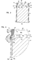
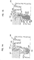
- Fig. 3 is a cross-sectional view taken along line 3-3, Fig. 2 .
- the cross-section of Fig. 3 is through the shorter or narrower dimension of the element 1, Fig. 1 .
- similar features will be viewable, if the cross-section were taken along the longer axis, i.e., line Y-Y, Fig. 2 .
- the media pack 2, Fig. 3 is a coiled media pack.
- the media pack 2 comprises a corrugated media sheet secured to a facing sheet, often a flat or nearly flat sheet, to form a strip or single facer, which is itself coiled in the configuration shown.
- the media pack 2 comprises a single strip of the corrugated sheet facing (typically flat or non-corrugated) sheet, or single facer, coiled and configured as shown.
- the outer three coils are indicated. Referring to Fig. 1 , the outside tail end of the outer most coil is shown at 37.
- tail end 37 is sealed and secured in position, by a hot melt sealant strip 38, although alternatives are possible.
- center board there is no center board, center gap, center piece or center seal schematically shown in the media pack 2.
- the media pack 2 is simply shown schematically with respect to this point.
- Center boards can be used, for example as described in U.S. 6,348,084 .
- Interdigitated center strips can be used, for example as described in U.S. Provisional Application Serial Number 60/467,521, filed May 2, 2003 .
- Center seals can also be used, for example as described in U.S. Provisional Application Serial Number 60/467,521, filed May 2, 2003 . No specific choice from among these, and variants, is meant to be indicated with respect to Fig. 3 .
- a center of the media pack 2 would be sealed closed, in some manner, to prevent the flow of unfiltered air between the two opposite end faces 15, 16; i.e., so unfiltered are cannot flow outwardly from an end face.
- the preform part 35 depicted includes three sections generally comprising: housing seal support section 40; media engagement periphery or skirt 41; and, media face cross piece arrangement 43.
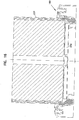
- Fig. 4 is a fragmentary enlarged view of a portion of Fig. 3 .
- media engagement portion 41 includes an edge 45 which is brought into engagement with flow face 16 of the z-filter media pack 2 and which for the example shown does not project to, or beyond, an outer perimeter edge 16a of flow face 16, although alternatives are possible.
- the particular preform 35 depicted includes a small ridge 45a, Fig. 6 which projects slightly into media pack 2.
- ridge 45a is no greater than 1 mm and comes to a fine point, to help contain flow of rising urethane, during formation of the overmold 36, and desirably from extending across flow face 16.
- the particular z-filter media pack 2 depicted comprises a coiled media arrangement.
- the outer three coils 46a, 46b and 46c are formed.
- the ends of coils 46a, 46b and 46c, adjacent surface 16, are shown comprising ends folded or darted closed at 47.
- folding or darting is described, for example, in U.S. Provisional Application Serial Number 60/467,521, filed May 2, 2003 .
- molded seal component 36 is positioned with a portion 48 overlapping and sealing a joint 49 where preform part 35 engages flow surface 16 of the media pack 2.
- the molded seal component 36 includes a portion 51 which extends beyond the joint 49 in a direction away from flow face 16 (toward opposite flow face 15, Fig. 3 ) a distance of at least 5 mm, preferably at least 8 mm, and typically a distance within the range of about 9 mm to 18 mm, inclusive.
- portions 48 and 51 of the molded seal component 36 provide then, for a sealing between the media pack 2 and the preform part 35 at this location, and also for sealing around and against media pack 2, adjacent face 16, to inhibit undesired, contaminated, air flow at this region.
- portions 48 and 51 will contact the single facer sheet of the media directly. In other cases, material on the media pack will be between the media and portions 48 and 51. In both instances, portions 48 and 51 engage the media pack 2.
- the strip 38 is continuous and terminates, underneath region 51 of overmold 36, at a location spaced at least 4 mm from face 16, Fig. 4 .
- an extension of 6-12 mm of strip 38 will be positioned underneath overmold 36.
- the termination of strip 38 at least 4 mm from surface 16 ensures that over a distance of at least 4 mm, the seal material of overmold 36 is sealed directly to the media pack 2 adjacent end face 16. This will help avoid leak between the overmold 36 and the media pack 2 at this location.
- Air cleaner seal portion 54 includes a radial outer surface 56, configured in a preferred manner, for sealing with an air cleaner component.
- the particular surface 56 is depicted, as a stepped surface portion 56a having a shape similar to the shape of the seal surface portion at reference 250 depicted in U.S. patent 6,350,291 at Fig. 7 .
- portion 40 of preform part 35 is positioned to back up housing seal 56 and stepped portion 56a of molded seal composition or overmold 36.
- preform part 35 serves a function of providing for rigid backup to the strength of the seal when air cleaner seal portion 54 is compressed in the thickness (preferably at least 10% in thickness at the portion of most compression) upon installation in an air cleaner, with compression being of surface 56 toward portion 40.
- the distance of compression is within the range of 1.5 - 2.8 mm, at the thickest part 56b of seal 56, more preferably about 1.9 - 2.5 mm.
- portion 40 is positioned to operate as a backup to the seal, because it projects outwardly (axially) from one of the flow faces 15, 16.
- the recess of surface 40 across face 16, from outer periphery 2a of the media pack 2, provides that the filter element 1 can be installed in air cleaners that are originally configured, for example, to receive elements such as element 450, Fig. 15 of U.S. patent 6,350,291 .
- the filter element 1 can be installed in air cleaners that are originally configured, for example, to receive elements such as element 450, Fig. 15 of U.S. patent 6,350,291 .
- surface 40 is preferably positioned so the supported housing seal 56 projects at or outwardly from the outer perimeter of the media pack, in preferred arrangements.
- Media engagement portion 41 is configured to extend radially outwardly, in extension between portion 40 and edge 57.
- Media engagement portion 41 is configured as a radially outwardly directed skirt, from region 40.
- This outward extension means that ends of outlet flutes in the z-filter media pack 2, at region 60, Fig. 3 , are not closed to passage of air therefrom, during filtering operation. If region 41 was not positioned as a flared, diagonal, skirt, but rather section 40 extended to point 61, flutes in region 60 would be blocked by extension 41, for air flow therefrom. This would lead to increased restriction, and less efficient use of the media.
- angle X Fig. 6
- the angle X is the angle between the inside surface of skirt 41 and the media face 16.
- skirt 41 is sized and positioned to leave region 64 in face 16 (corresponding to the otherwise open ends of exit flutes in an outer flute wrap 46a in the media pack 2), exposed to receive a portion of molded seal component 36 therein, as indicated at 66.
- This can provide for advantage. In particular, this allows some of overmold 36 to rise into the media pack 2, as described below, during molding.
- no portion of the molded seal component 36 is positioned along interior surface 40a of section 40. Further, preferably no portion of molded seal component 36 is provided along inner surface 41a of region 41, except possibly for some bleed or flash immediately adjacent edge 45. This latter prevents undesired levels of flash across surface 16 and provides for a convenient manufacture. Section 40 could be configured, and overmold 36 formed, to allow sealant in region 40a, but this would not be preferred.
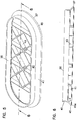
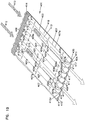
- media face cross piece arrangement 43 extends across media face 16, in engagement with region 41 of preformed part 35.
- Media face cross piece arrangement 43 prevents the media pack 2 from telescoping, in the direction of arrow 10, Fig. 1 , during use.
- cross piece arrangement 43 comprises: a grid of parallel extensions 43a between opposite sides 22, 23; interconnected by diagonal framework 43b.
- a perspective view is provided, showing preformed part 35.
- the preform part 35 can be formed as a single integral unit, for example through injection molding or other molding processes. It is preferably formed from a polymer such as a (33% for example) glass filled nylon material.
- molded overmold or seal component 36 includes a portion 70 overlapping part of end 71 of preform part 35. This is an artifact from a preferred molding operation, as described below.
- the overmold 36 in its thickest location, could be about 10 - 12 mm thick, for example about 11.5 mm.
- the longest cross-sectional dimension of the racetrack shaped media pack could be about 300 - 320 mm, for example about 308 mm.
- the shortest cross-sectional dimension of the racetrack shaped element could about 115 - 125 mm, for example about 121 mm.
- the length of the straight sides could be about 175 - 195 mm, for example about 188 mm.
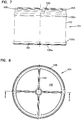
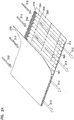
- Fig. 7 is a side elevational view of a serviceable filter element (or cartridge) 101.
- the filter element 101 comprises a z-filter media pack 102 and seal arrangement 103.
- the element 101 further includes optional end piece 104 at an end 102b of media pack 102 opposite from an end 102a in which seal arrangement 103 is located.
- the media pack 102 comprises a coiled single facer having first and second, opposite, flow faces 105, 105a. It would, of course, have an outside tail end, not shown, which would be secured down, for example, with a sealant strip analogous to strip 38 above.
- surface 106 of seal arrangement 103 is configured to provide a seal, as an outwardly directed radial seal, with a housing or air cleaner component in use (of course alternatives are possible).
- Surface 106 may be configured, in cross-section, analogously to surface 56, Fig. 4 .
- FIG. 8 Attention is now directed to Fig. 8 , in which element 101 is depicted in top plan view. From the view of Fig. 7 , it can be seen that element 101 is a generally circular outer perimeter 108 defined by both the outer circumference of the seal arrangement 103 and media pack 102. In Fig. 8 , grid work 109 is viewable, extending across flow face 105; in this instance face 105 preferably being an outlet flow face.
- Fig. 9 shows a cross-sectional view through element 101.
- the seal arrangement 103 comprises a preformed part 110 and an overmold or molded seal component 111.
- the preform part 110 and molded seal component 111 may generally be analogous to the preform part 35 and molded seal component 36 of the embodiment shown in Figs. 1-5 , except made round.
- element 101 includes a core 113, around which the media pack 102 is wound.
- Core 113 can be provided in snap fit engagement with a portion 114 of preform part 110.
- a variety of engagement arrangements can be used, including the one, for example, described at Fig. 5 in U.S. Patent 6,517,598 .
- Core 113 is shown in schematic. It would typically be provided with a plug therein. The plug could be integral with a remainder of core 113 or be added thereto. The plug or other closure in core 113 would generally operate to prevent flow between faces 105a, 105 which is not filtered.
- the preform part 110 includes a housing seal support 116; and, a media pack engagement portion 117, configured as a radially outwardly directed skirt 118; and media face cross piece arrangement 109 ( Fig. 8 ). (At region 114 the inside outward skirt 118 is shown filled because the cross-section is taken through cross piece grid work 109, Fig. 8 .)
- these components generally provide the same basic operation as the analogous components for element 1, Fig. 1 .
- the term "overmolding" and variants thereof are meant to refer to molding a molded seal component 36, 111 in position: (a) with a portion of the molded seal component 36 over the outside of joint between the preformed part (35, 110) of the seal arrangement and the media pack (2, 102); and, (b) with a portion of the same seal component 36, 111 (i.e. preferably a portion integral with a remainder of the overmold) positioned to form an air cleaner seal.
- Typical and preferred processes will use, for the formation of the molded seal component, a foaming polyurethane, as described below.
- a molded seal component 36 which has been made by overmolding as defined will sometimes be referred to as an overmold.
- the portions of the overmold seal are preferably integral with one another; the overmold 36, 111 being preferably molded from a single pool of polymer.
- the thickness of the molded seal component, in the region of the seal surface is configured so that compression of the thickness of the thickest portion of the molded seal component in this region, will be at least 10%, and typically at least 15%, when the element (1, 101) is installed in an air cleaner for use. This can be accomplished with configurations as shown, using materials as described below.
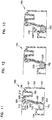
- reference numeral 180 identifies a mold arrangement useable to form the overmold seal arrangement of the present disclosure.
- Mold arrangement 180 is shown in fragmentary, cross-section. The portions indicated will provide an understanding of how the overmold seal arrangement can be formed. The remainder of the mold will be configured either round or obround, etc., depending on the particular instance of application.
- the particular mold arrangement 180 depicted is a multi-part mold 181. That is, the mold 180 includes more than one piece fit together, to form the mold in which the overmolding process occurs.
- the particular multi-part mold 180 depicted comprises three parts 183, 184 and 185 that are fit together, to form the mold.
- Aperture 189 which extends through three parts 183, 184, 185 when they are appropriately aligned, Fig. 11 , can be used to receive a pin or similar member to secure the mold together.
- part 183 forms the basic mold structure including: an inner reservoir portion 192, in which uncured resin is placed, for the molding process; inner wall 193, against which a preformed part would be placed in use; shelf 194 on which an edge of the preform part would rest, during the molding process; central wall 195 and shelf 196 which supports additional mold parts as described; and, outer wall 197, which provides an outer support structure to the assembly 180.
- the second part 184 comprises a mold insert having an extension 200 with a surface 201 that forms a portion of the outer surface of the molded part of the seal arrangement in use.
- surface 201 includes a portion 202 which, in combination with central wall 195 provides a mold undercut 203 molding a particular portion of the sealing surface of the resulting seal portion, as discussed below in connection with Fig. 15 .
- Part 184 further includes upper extension 205 which rests on shoulder 196.
- part 185 includes inner wall 215 and upper flange 218.
- the flange 218 extends over portion 205 of center part 184.
- Inner wall 215 includes a surface 216 which will define selected portions of the seal member, during the molding process, as discussed below in connection with Fig. 15 .
- Section 217 will cap the mold, and engage media, during a preferred molding operation.
- Fig. 12 in which assembly 180 is depicted with curable material 225 positioned within reservoir 192 up to fill line 226.
- the material 225 would generally comprise resin which, during a cure process, will foam and rise as a cure to form the moldable seal component. Typically, during molding and use the material 225 will expand in volume at least 80%, a preferred material increasing about 100%, in volume.
- the mold assembly 180 having resin 225 therein is shown having preformed part 230 therein.
- the preform part 230 could correspond, for example, to preform part 35, Fig. 1 . It could also correspond to preform part 110, Fig. 7 . However if used with the arrangement of Fig. 7 , in some instances it would already be attached to the media pack.
- Fig. 14 Attention is now directed to Fig. 14 in which the mold arrangement 180 is depicted with preform part 230 and media pack 231 positioned appropriately. It is noted that an outer surface 232 of media pack 231 is sized to engage portion 217 of the mold part 185.
- Fig. 15 the material at 235 is meant to indicate the foamed, risen, substantially cured resin; i.e., the overmold (corresponding to overmold 36, Fig. 1 , or overmold 103, Fig. 7 ).
- substantially cured it is meant that the resin is cured sufficiently to have reached a shape which will generally be maintained, as it further cures. From Fig. 15 , some of the following important features relating to the molding operation can be understood:
- the media pack is one which has closed ends at the inlet flutes, adjacent the outlet flow face, darted closed, to provide the edges viewable. Alternates of course are possible, including ones that are not darted at all.
- the overmold material is shown risen up into the open ends of the outlet flutes, at the outlet face of the media, in the region indicated at 247.
- the resin material 236 completely lines an outer surface of preform 230, securing it in place.
- material 235 is positioned over a part of an end 256 of preform 230.
- the overmold 235 is a single integral member, molded from the resin 225, Fig. 14 .
- Demolding can be accomplished by forcing the element out of the mold 180, in a powered process. Equipment to cause the forcing can engage the cross pieces on the preform 230. Generally the overmold 235 will compress sufficiently, to be pushed past undercuts in the mold. It is anticipated that typically, with materials and configurations described herein, demolding can be accomplished with a force of 110 lbs. or less, typically about 100 lbs. (The demolding force would typically be applied directly to the gridwork of the preform 35, 110.)
- the optional preform skid skirt at the opposite end of the element can be applied either before or after molding.
- a center plug In general, if a center plug is used within the media, it would be preformed before the described molding process. However, in some instances a center plug can be molded at the same time as the overmold. This latter would require ensuring that a part of the mold or some other configuration is provided, for appropriate dispensing of the urethane to accomplish this.
- the preform 230 could be attached to the media pack 231 by snap-fit arrangement.
- Fig. 16 the mold 180 is depicted with the media pack 231 and preform 230 positioned therein, at molding. In this instance the media pack 231 is depicted without the option skid skirt mounted therein.
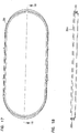
- skid skirt 30 was an optional component. This component is depicted in Figs. 17 and 18 .
- a top plan view the skid skirt 30 is depicted.
- the skid skirt 30 is depicted in cross-sectional view.
- receiving area 30a for the media pack can be viewed, along with outside surface 30b configured to engage componentry in a housing, during installation, as desired.
- an analogous, but circular, component can be understood, if desired, for application in a circular arrangement.
- the skid skirt 30 is typically formed from a glass filled (for example 33% glass filled) nylon, secured in position with an adhesive.
- the polyurethane formulation chosen provides for a high foam, very soft, molded end cap.
- the principal issue is to utilize a formulation that provides for an end cap that is such that a robust seal will result under conditions which will allow for hand assembly and disassembly. This generally means that the seal range which has material is a relatively low density, and exhibits appropriate and desirable compression load deflection and compression set.
- the formula chosen will be such as to provide end caps having an as molded density of no greater than 28 lbs./cubic foot (0.45 g/cu. cm.), more preferably no more than 22 lbs./cubic foot (0.35 g/cu. cm.), typically no greater than 18 lbs/cubic foot (0.29 g/cu. cm.) and preferably within the range of 12 to 17 lbs/cubic foot (0.19 - 0.27 g/cu. cm.).
- molded density is meant to refer to its normal definition of weight divided by volume.
- a water displacement test or similar test can be utilized to determine volume of a sample of the molded foam. It is not necessary when applying the volume test, to pursue water absorption into the pores of the porous material, and to displace the air the pores represent. Thus, the water volume displacement test used, to determine sample volume, would be an immediate displacement, without waiting for a long period to displace air within the material pores. Alternately stated, only the volume represented by the outer perimeter of the sample need be used for the as molded density calculation.
- compression load deflection is a physical characteristic that indicates firmness, i.e. resistance to compression. In general, it is measured in terms of the amount of pressure required to deflect a given sample of 25% of its thickness. Compression load deflection tests can be conducted in accord with ASTM 3574. In general, compression load deflection may be evaluated in connection with aged samples. A typical technique is to measure the compression load deflection on samples that have been fully cured for 72 hours at 75°F (24°C) or forced cured at 190°F (88°C) for 5 hours.
- Preferred materials will be ones which when molded, show a compression load deflection, in accord with ASTM 3574, on a sample measured after heat aging at 158° F (70°C) for seven days, on average, of 14 psi (0.96 bar) or less, typically within the range of 6-14 psi (0.41 - 0.96 bar), and preferably within the range of 7-10 psi (0.48 - 0.69 bar).
- Compression set is an evaluation of the extent to which a sample of the material (that is subjected to compression of the defined type and under defined conditions), returns to its previous thickness or height when the compression forces are removed.
- Conditions for evaluating compression set on urethane materials are also provided in ASTM 3574.
- Typical desirable materials will be ones which, upon cure, provide a material that has a compression set of no more than about 18%, and typically about 8-13%, when measured on a sample compressed to 50% of its height and held at that compression at a temperature of 180°F (82°C) for 22 hours.
- the compression load deflection and compression set characteristics can be measured on sample plugs prepared from the same resin as used to form the end cap, or on sample cut from the end cap.
- industrial processing methods will involve regularly making test sample plugs made from the resin material, rather than direct testing on portions cut from molded end caps.
- Urethane resin systems useable to provide materials having physical properties within the as molded density, compression set and compression load deflection definition as provided above, can be readily obtained from a variety of polyurethane resin formulators, including such suppliers as BASF Corp., Wyandotte MI, 48192.
- One example usable material includes the following polyurethane, processed to an end product having an "as molded" density of 14-22 pounds per cubic foot (0.22 g/cu. cm. - 0.35 g/cu. cm.)
- the polyurethane comprises a material made with I36070R resin and I305OU isocyanate, which are sold exclusively to the assignee Donaldson by BASF Corporation, Wyandotte, Michigan 48192.
- the materials would typically be mixed in a mix ratio of 100 parts I36070R resin to 45.5 parts I305OU isocyanate (by weight).
- the specific gravity of the resin is 1.04 (8.7 lbs/gallon) and for the isocyanate it is 1.20 (10 lbs/gallon).
- the materials are typically mixed with a high dynamic shear mixer.
- the component temperatures should be 70-95°F.
- the mold temperatures should be 115-135°F.
- the resin material I36070R has the following description:
- the I3050U isocyanate description is as follows:
- the portion of the resin that forms in the housing seal should typically be a material that cures to a density of at least 10 lbs./cubic foot (0.16 grams/cc) would be preferred, although materials as low as 5 lbs./cubic foot (0.08 grams/cc) maybe acceptable for some light duty applications. Again it would be preferred that the material be one which cures to a density of no greater than about 22 lbs./cubic foot (0.35 grams/cc), as discussed above, and preferably less than this value.
- media packs usable in the arrangements described for example as media packs 2, 102, comprise z-filter media packs. It was indicated that a variety of alternate flute shapes and seal types can be used in such media packs.
- Fluted filter media can be used to provide fluid filter constructions in a variety of manners.
- One well known manner is as a z-filter construction.
- the term "z-filter construction" as used herein, is meant to refer to a filter construction in which individual ones of corrugated, folded or otherwise formed filter flutes are used to define sets of longitudinal, typically parallel, inlet and outlet filter flutes for fluid flow through the media; the fluid flowing along the length of the flutes between opposite inlet and outlet flow ends (or flow faces) of the media.
- Some examples of z-filter media are provided in U.S.
- One type of z-filter media utilizes two specific media components joined together, to form the media construction.
- the two components are: (1) a fluted (typically corrugated) media sheet; and, (2) a facing media sheet.
- the facing media sheet is typically non-corrugated, however it can be corrugated, for example perpendicularly to the flute direction as described in U.S. provisional 60/543,804, filed February 11, 2004 .
- the fluted (typically corrugated) media sheet and the facing media sheet together are used to define media having parallel inlet and outlet flutes.
- the fluted sheet and facing sheet are secured together and are then coiled to form a z-filter media construction.
- Such arrangements are described, for example, in U.S. 6,235,195 and 6,179,890 .
- some non-coiled sections of fluted media secured to facing media are stacked on one another, to create a filter construction. An example of this is described in Fig. 11 of 5,820,646.
- coiled arrangements are preferred.
- coiling of the fluted sheet/facing sheet combination around itself, to create a coiled media pack is conducted with the facing sheet directed outwardly.
- Some techniques for coiling are described in U.S. provisional application 60/467,521, filed May 2, 2003 and PCT Application US 04/07927, filed March 17, 2004 .
- the resulting coiled arrangement generally has, as the outer surface of the media pack, a portion of the facing sheet.
- corrugated used herein to refer to structure in media, is meant to refer to a flute structure resulting from passing the media between two corrugation rollers, i.e., into a nip or bite between two rollers, each of which has surface features appropriate to cause a corrugation affect in the resulting media.
- corrugation is not meant to refer to flutes that are formed by techniques not involving passage of media into a bite between corrugation rollers.
- corrugated is meant to apply even if the media is further modified or deformed after corrugation, for example by the folding techniques described in PCT WO 04/007054, published January 22, 2004 .
- Corrugated media is a specific form of fluted media.
- Fluted media is media which has individual flutes (for example formed by such techniques as corrugating or folding) extending thereacross.
- Serviceable filter element or filter cartridge configurations utilizing z-filter media are sometimes referred to as "straight through flow configurations" or by variants thereof.
- the serviceable filter elements generally have an inlet flow end (or face) and an opposite exit flow end (or face), with flow entering and exiting the filter cartridge in generally the same straight through direction.
- the media pack is closed to passage therethrough of unfiltered air.
- serviceable in this context is meant to refer to a media containing filter cartridge that is periodically removed and replaced from a corresponding fluid cleaner.
- each of the inlet flow end and outlet flow end will be generally flat or planar, with the two parallel to one another. However, variations from this, for example non-planar faces are possible.
- a straight through flow configuration (especially for a coiled media pack) is, for example, in contrast to serviceable filter cartridges such as cylindrical pleated filter cartridges of the type shown in U.S. Patent No. 6,039,778 , in which the flow generally makes a turn as its passes through the serviceable cartridge. That is, in a 6,039,778 filter, the flow enters the cylindrical filter cartridge through a cylindrical side, and then turns to exit through an end face (in forward-flow systems). In a typical reverse-flow system, the flow enters the serviceable cylindrical cartridge through an end face and then turns to exit through a side of the cylindrical filter cartridge. An example of such a reverse-flow system is shown in U.S. Patent No. 5,613,992 .
- z-filter media construction and variants thereof as used herein, without more, is meant to refer to any or all of: a web of corrugated or otherwise fluted media secured to facing media with appropriate sealing to allow for definition of inlet and outlet flutes; or, such a media coiled or otherwise constructed or formed into a three dimensional network of inlet and outlet flutes; and/or, a filter construction including such media.
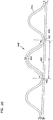
- FIG. 19 an example of media 401 useable in z-filter media is shown.
- the media 401 is formed from a corrugated (fluted) sheet 403 and a facing sheet 404.
- the corrugated sheet 403, Fig. 19 is of a type generally characterized herein as having a regular, curved, wave pattern of flutes or corrugations 407.
- wave pattern in this context, is meant to refer to a flute or corrugated pattern of alternating troughs 407b and ridges 407a.
- regular in this context is meant to refer to the fact that the pairs of troughs and ridges (407b, 407a) alternate with generally the same repeating corrugation (or flute) shape and size.
- each trough 407b is substantially an inverse of each ridge 407a.
- the term “regular” is thus meant to indicate that the corrugation (or flute) pattern comprises troughs and ridges with each pair (comprising an adjacent trough and ridge) repeating, without substantial modification in size and shape of the corrugations along at least 70% of the length of the flutes.
- substantially in this context, refers to a modification resulting from a change in the process or form used to create the corrugated or fluted sheet, as opposed to minor variations from the fact that the media sheet 403 is flexible.
- the media 401 could be terminated, for example, between a pair comprising a ridge and a trough, or partially along a pair comprising a ridge and a trough. (For example, in Fig. 19 the media 401 depicted in fragmentary has eight complete ridges 407a and seven complete troughs 407b.) Also, the opposite flute ends (ends of the troughs and ridges) may vary from one another. Such variations in ends are disregarded in these definitions, unless specifically stated. That is, variations in the ends of flutes are intended to be covered by the above definitions.
- curved is meant to refer to a corrugation pattern that is not the result of a folded or creased shape provided to the media, but rather the apex 407a of each ridge and the bottom 407b of each trough is formed along a radiused curve.
- a typical radius for such z-filter media would be at least 0.25 mm and typically would be not more than 3 mm. (Media that is not curved, by the above definition, can also be useable.)
- trough 407b is a concave region
- ridge 407a is a convex region.
- region 430 can be a straight segment, instead of a point, with curvature inverting at ends of the straight segment 430.
- a characteristic of the particular regular, curved, wave pattern corrugated sheet 403 shown in Fig. 19 is that the individual corrugations are generally straight.
- straight in this context, it is meant that through at least 70% (typically at least 80%) of the length between edges 408 and 409, the ridges 407a and troughs 407b do not change substantially in cross-section.
- the term "straight" in reference to corrugation pattern shown in Fig. 19 in part distinguishes the pattern from the tapered flutes of corrugated media described in Fig. 1 of WO 97/40918 and PCT Publication WO 03/47722, published June 12, 2003 .
- the tapered flutes of Fig. 1 of WO 97/40918 for example, would be a curved wave pattern, but not a "regular” pattern, or a pattern of straight flutes, as the terms are used herein.
- the media 401 has first and second opposite edges 408 and 409.
- edge 409 When the media 401 is coiled and formed into a media pack, in general edge 409 will form an inlet end for the media pack and edge 408 an outlet end, although an opposite orientation is possible.
- Adjacent edge 408 the sheets 403, 404 are sealed to one another, for example by sealant, in this instance in the form of a sealant bead 410, sealing the corrugated (fluted) sheet 403 and the facing sheet 404 together.
- Bead 410 will sometimes be referred to as a "single facer" bead, when it is applied as a bead between the corrugated sheet 403 and facing sheet 404, to form the single facer or media strip 401.
- Sealant bead 410 seals closed individual flutes 411 adjacent edge 408, to passage of air therefrom.
- Adjacent edge 409 is provided sealant, in this instance in the form of a seal bead 414.
- Seal bead 414 generally closes flutes 415 to passage of unfiltered fluid therein, adjacent edge 409.
- Bead 414 would typically be applied as the media 401 is coiled about itself, with the corrugated sheet 403 directed to the inside.
- bead 414 will form a seal between a back side 417 of facing sheet 404, and side 418 of the corrugated sheet 403.
- the bead 414 will sometimes be referred to as a "winding bead" when it is applied as the strip 401 is coiled into a coiled media pack. If the media 401 were cut in strips and stacked, instead of coiled, bead 414 would be a "stacking bead.”
- the corrugated sheet 403 is also tacked to the facing sheet 4 at various points along the flute length, as shown at lines 404a.
- the media 401 can be operated as follows. First, air in the direction of arrows 412, would enter open flutes 411 adjacent end 409. Due to the closure at end 408, by bead 410, the air would pass through the media shown by arrows 413. It could then exit the media pack, by passage through open ends 415a of the flutes 415, adjacent end 408 of the media pack. Of course operation could be conducted with air flow in the opposite direction, as discussed for example with respect to Fig. 24 . The point being that in typical air filter applications, at one end or face of the media pack unfiltered air flow goes in, and at an opposite end or face the filtered air flow goes out, with no unfiltered air flow through the pack or between the faces.
- the parallel corrugations 7a, 7b are generally straight completely across the media, from edge 708 to edge 709.
- Straight flutes or corrugations can be deformed or folded at selected locations, especially at ends. Modifications at flute ends for closure are generally disregarded in the above definitions of "regular,” “curved” and “wave pattern.”
- the filter media is a relatively flexible material, typically a non-woven fibrous material (of cellulose fibers, synthetic fibers or both) often including a resin therein, sometimes treated with additional materials.
- a non-woven fibrous material of cellulose fibers, synthetic fibers or both
- a resin therein
- it can be conformed or configured into the various corrugated patterns, without unacceptable media damage.
- it can be readily coiled or otherwise configured for use, again without unacceptable media damage.
- it must be of a nature such that it will maintain the required corrugated configuration, during use.
- the media contains a resin.
- the media can be heated to above the glass transition point of the resin. When the resin then cools, it will help to maintain the fluted shapes.
- the media of the corrugated sheet 403, facing sheet 404 or both can be provided with a fine fiber material on one or both sides thereof, for example in accord with U.S. 6,673,136 .
- a z-filter media construction 440 utilizing a regular, curved, wave pattern corrugated sheet 443, and a facing (in this instance non-corrugated) sheet 444, is depicted.
- the distance D1, between points 450 and 451, defines the extension of facing media 444 in region 452 underneath a given corrugated flute 453.
- the length D2 of the arcuate media for the corrugated flute 453, over the same distance D1 is of course larger than D1, due to the shape of the corrugated flute 453.
- the linear length D2 of the media 453 between points 450 and 451 will generally be at least 1.2 times D1.
- D2 would be within a range of 1.2 - 2.0 time D1, inclusive.
- One particularly convenient arrangement for air filters has a configuration in which D2 is about 1.25 - 1.35 x D1.
- Such media has, for example, been used commercially in Donaldson PowercoreTM Z-filter arrangements.
- the ratio D2/D1 will sometimes be characterized as the flute/flat ratio or media draw for the corrugated (fluted) media.
- DCI A Flute: Flute/flat 1.52:1;
- DCI B Flute: Flute/flat 1.32:1;
- E Flute: Flute/flat 1.24:1;
- X Flute: Flute/flat 1.29:1;
- a Flute: Flute/flat 1.53:1;
- standard flute configurations from the corrugated box industry can be used to define corrugation shapes or approximate corrugation shapes for corrugated media. Comparisons above between the DCI A flute and DCI B flute, and the corrugation industry standard A and standard B flutes, indicate some convenient variations.
- Fig. 22 one example of a manufacturing process for making a media strip corresponding to strip 401, Fig. 19 is shown.
- facing sheet 464 and the fluted (corrugated) sheet 466 having flutes 468 are brought together to form a media web 469, with an adhesive bead located therebetween at 470.
- the adhesive bead 470 will form a single facer bead 410, Fig. 19 .
- An optional darting process occurs at station 471 to form center darted section 472 located mid-web.
- the z-filter media or Z-media strip 474 can be cut or slit at 475 along the bead 470 to create two pieces 476, 477 of z-filter media 474, each of which has an edge with a strip of sealant (single facer bead) extending between the corrugating and facing sheet.
- a strip of sealant single facer bead
- the edge with a strip of sealant would also have a set of flutes darted at this location.
- tack beads or other tack connections 404a, Fig. 19 are used, they can be made, as the sheets 464, 466 are brought together.
- the z-filter media 474 before the z-filter media 474 is put through the darting station 471 and eventually slit at 475, it must be formed. In the schematic shown in Fig. 22 , this is done by passing a sheet of media 492 through a pair of corrugation rollers 494, 495. In the schematic shown in Fig. 22 , the sheet of media 492 is unrolled from a roll 496, wound around tension rollers 498, and then passed through a nip or bite 502 between the corrugation rollers 494, 495.
- the corrugation rollers 494, 495 have teeth 504 that will give the general desired shape of the corrugations after the flat sheet 492 passes through the nip 502.
- the sheet 492 After passing through the nip 502, the sheet 492 becomes corrugated across the machine direction and is referenced at 466 as the corrugated sheet.
- the corrugated sheet 466 is then secured to facing sheet 464. (The corrugation process may involve heating the media, in some instances.)
- the process also shows the facing sheet 464 being routed to the darting process station 471.
- the facing sheet 464 is depicted as being stored on a roll 506 and then directed to the corrugated sheet 466 to form the Z-media 474.
- the corrugated sheet 466 and the facing sheet 464 are secured together by adhesive or by other means (for example by sonic welding).
- an adhesive line 470 is shown used to secure corrugated sheet 466 and facing sheet 464 together, as the sealant bead.
- the sealant bead for forming the facing bead could be applied as shown as 470a. If the sealant is applied at 470a, it may be desirable to put a gap in the corrugation roller 495, and possibly in both corrugation rollers 494, 495, to accommodate the bead 470a.
- corrugation The type of corrugation provided to the corrugated media is a matter of choice, and will be dictated by the corrugation or corrugation teeth of the corrugation rollers 494, 495.
- One preferred corrugation pattern will be a regular curved wave pattern corrugation of straight flutes, as defined herein above.
- the techniques may be applied with curved wave patterns that are not "regular," including, for example, ones that do not use straight flutes.
- Fig. 22 shows, in cross-section, one of the flutes 468 after darting and slitting.
- a fold arrangement 518 can be seen to form a darted flute 520 with four creases 521a, 521b, 521c, 521d.
- the fold arrangement 518 includes a flat first layer or portion 522 that is secured to the facing sheet 464.
- a second layer or portion 524 is shown pressed against the first layer or portion 522.
- the second layer or portion 524 is preferably formed from folding opposite outer ends 526, 527 of the first layer or portion 522.
- FIG. 23 two of the folds or creases 521a, 521b will generally be referred to herein as "upper, inwardly directed" folds or creases.
- the term “upper” in this context is meant to indicate that the creases lie on an upper portion of the entire fold 520, when the fold 520 is viewed in the orientation of Fig. 23 .
- the term “inwardly directed” is meant to refer to the fact that the fold line or crease line of each crease 521a, 521b, is directed toward the other.
- creases 521c, 521d will generally be referred to herein as “lower, outwardly directed” creases.
- the term “lower” in this context refers to the fact that the creases 521c, 521d are not located on the top as are creases 521a, 521b, in the orientation of Fig. 23 .
- the term “outwardly directed” is meant to indicate that the fold lines of the creases 521c, 521d are directed away from one another.
- upper and lower as used in this context are meant specifically to refer to the fold 520, when viewed from the orientation of Fig. 23 . That is, they are not meant to be otherwise indicative of direction when the fold 520 is oriented in an actual product for use.
- a preferred regular fold arrangement 518 according to Fig. 23 in this disclosure is one which includes at least two "upper, inwardly directed, creases.” These inwardly directed creases are unique and help provide an overall arrangement in which the folding does not cause a significant encroachment on adjacent flutes.
- a third layer or portion 528 can also be seen pressed against the second layer or portion 524.
- the third layer or portion 528 is formed by folding from opposite inner ends 530, 531 of the third layer 528.
- the first layer or portion 522 is formed from an inverted ridge.
- the second layer or portion 524 corresponds to a double peak (after inverting the ridge) that is folded toward, and in preferred arrangements folded against, the inverted ridge.
- Techniques described herein are particularly well adapted for use with media packs that result from coiling a single sheet comprising a corrugated sheet/facing sheet combination, i.e., a "single facer" strip. Certain of the techniques can be applied with arrangements that, instead of being formed by coiling, are formed from a plurality of strips of single facer.
- Coiled media pack arrangements can be provided with a variety of peripheral perimeter definitions.
- peripheral, perimeter definition and variants thereof, is meant to refer to the outside perimeter shape defined, looking at either the inlet end or the outlet end of the media pack.
- Typical shapes are circular as described in PCT WO 04/007054 and PCT application US 04/07927 .
- Other useable shapes are obround, some examples of obround being oval shape.
- oval shapes have opposite curved ends attached by a pair of opposite sides.
- the opposite sides are also curved.
- racetrack shapes the opposite sides are generally straight. Racetrack shapes are described for example in PCT WO 04/007054 and PCT application US 04/07927 .
- Another way of describing the peripheral or perimeter shape is by defining the perimeter resulting from taking a cross-section through the media pack in a direction orthogonal to the winding axis of the coil.
- Opposite flow ends or flow faces of the media pack can be provided with a variety of different definitions.
- the ends are generally flat and perpendicular to one another.
- the end faces include tapered, coiled, stepped portions which can either be defined to project axially outwardly from an axial end of the side wall of the media pack; or, to project axially inwardly from an end of the side wall of the media pack. Examples of such media pack arrangements are shown in US Provisional Application 60/578,482, filed June 8, 2004 .
- the flute seals (for example from the single facer bead, winding bead or stacking bead) can be formed from a variety of materials.
- hot melt or polyurethane seals are described as possible for various applications. Such materials are also useable for arrangements as characterized herein.
- the media chosen for the corrugated sheet and facing sheet can be the same or different.
- Cellulose fiber, synthetic fiber or mixed media fiber materials can be chosen.
- the media can be provided with a fine fiber layer applied to one or more surface, for example in accord with U.S. patent 6,673,136, issued January 6, 2004 . When such material is used on only one side of each sheet, it is typically applied on the side(s) which will form the upstream side of inlet flutes.
- Fig. 24 a schematic depiction of media useable in such z-filter media packs as shown.
- the schematic depiction of Fig. 24 is generic, and is not meant to indicate unique or preferred seal type or flute shapes.
- the reference numeral 300 generally indicates a single facer comprising corrugated sheet 301 secured to flat sheet 302. It is noted that the flat sheet 302 does not have to be perfectly flat, it may comprise a sheet that itself has very small corrugations and other formations therein.
- Particular single facer 300 depicted could be coiled around itself or around a core and then around itself, typically with flat sheet 302 to the outside.
- edge 310 will form the inlet face in the eventual media pack and end or edge 311 will form the outlet flow faces.
- arrows 312 represent inlet arrows and arrows 313 represent outlet flow arrows.
- Sheet 315 is merely meant to schematically represent a flat sheet corresponding to sheet 302, of the next wind.
- Adjacent edge 311 is provided a single facer seal arrangement 320.
- the single facer shield arrangement 320 comprises a bead of sealant 321 between corrugated sheet 301 and flat sheet 302, positioned along edge 310 or within about 10% of the total length of the flutes, i.e., the distance between inlet edge 310 and outlet edge 311.
- the seal arrangement 320 could comprise a corrugated or folded arrangement, sealed with a sealant, or sealed by other means.
- the particular seal arrangement 320 depicted could comprise a bead of hot melt sealant, although alternatives are possible.
- the seals at 320 could be darted or folded, as shown for Figs. 4 and 10 .
- Winding seal 330 generally provides for a seal between layers adjacent edge 311, as the single facer 300 is coiled. Preferably winding seal 330 is positioned within 10% of the total length of the flutes (i.e., the distance between edge 311 and 310) of edge 310.
- sealant can be applied at these locations to do so.
- Fig. 25 One particular system is depicted schematically in Fig. 25 , generally at 650.
- equipment 652 such as a vehicle 652a having an engine 653 with some defined rated air flow demand, for example in the range of 50 cfm to 2000 cfm (cubic feet per minute) (i.e., 1.4-57 cubic meters/minute) is shown schematically.
- the equipment 652 may, for example, comprise a bus, an over-the-highway truck, an off-road vehicle, a tractor, a light-duty or medium-duty truck, or a marine vehicle such as a power boat.
- the engine 653 powers the equipment 652 upon fuel combustion.
- Fig. 25 One particular system is depicted schematically in Fig. 25 , generally at 650.
- equipment 652 such as a vehicle 652a having an engine 653 with some defined rated air flow demand, for example in the range of 50 cfm to 2000 cfm (cubic feet per minute) (i.e.,
- air flow is shown drawn into the engine 653 at an air intake at region 655.
- An optional turbo 656 is shown in phantom, as optionally boosting the air intake to the engine 653.
- the turbo 656 is shown downstream from an air cleaner 660, although alternate arrangement are possible.
- the air cleaner 660 has a filter cartridge 662 and is shown in the air inlet stream to the engine 653.
- air is drawn in at arrow 664 into the air cleaner 660 and through the filter cartridge 662.
- selected particles and contaminants are removed from the air.
- the cleaned air then flows downstream at arrow 666 into the intake 655. From there, the air flow is directed into the engine 653.
- the filter cartridge 662 is a serviceable component. That is, the cartridge 662 is removable and replaceable within the air cleaner 660. This allows the cartridge 662 to be serviced, by removal and replacement, with respect to remainder of air cleaner 660, when the cartridge 662 becomes sufficiently loaded with dust or other contaminant, to require servicing.
- the core 113 could be filled with a plug.
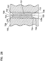
- An example is described below, and shown in Fig. 26 .
- Fig. 26 a fragmentary portion of media pack 102, Fig. 9 , is shown.
- the coiled media pack 102 includes center core 113.
- the core 113 needs to be sealed against unfiltered air flow therethrough. This is done by center piece, plug or core 721.
- Core 721 also provides for a lead end seal of the single facer strip which is coiled to form the media pack 102.
- the media lead end is shown in phantom at 722.
- the mold-in-place plug 721 is provided in center 113. Thus, it seals at least a portion of the lead end 724 of the media strip.
- the preferred plug 721 is a poured and cured core. By this it is meant that the plug 721 results from pouring a fluid resin into center 113 and allowing the resin to cure. A variety of shapes and sizes for the plug 721 are possible.
- the plug 721 when used as a lead end seal, the plug 721 will be configured to extend along, or engulf, at least 80% of the lead end seal length, typically at least 90% of that length. In some instances, for example in the instance shown in Fig. 26 , the plug 721 may be configured to cover or enclose the entire lead end 722.
- the plug 721 can be configured with recesses as shown, or it can be configured to have no recesses or even to have one or more projections extending outwardly from the element.
- region 724 will be spaced from end face 105 at least 2 mm, and region 725 will be spaced from end 105a by at least 2 mm.
- Region 727 extends from region 724 toward face 105, and terminates at face 105 as shown, or spaced therefrom within a preferred distance. This region defines an outer seal wall 728 with a hollow center 729. The seal wall 728 continues the sealing of the lead end 722 of the media pack 102. Region 727 can be viewed as a concave end to plug 721. Herein, region 727 will sometimes be referred to as a concave end with an axially outwardly projecting end skirt 728.
- Skirt 728 is not required to terminate at end face 105, although such termination is shown in the arrangement of Fig. 26 . It can terminate short thereof and can still accomplish much of its function of sealing the lead end 722, for example, by terminating at or adjacent the winding bead seal or single facer seal in this region.
- region 734 is provided, with outer seal area 735 and inner center recess 736.
- the seal area 735 provides, among other things, for sealing of the lead end 722 of the media 102 between region 725 and surface 105a.
- the seal area 735 can be seen as a concave end to plug 721.
- region 725 will sometimes be referred to as a concave end with an axially outwardly projecting end skirt 735.
- end skirt 735 is not required to terminate adjacent end face 105a, as shown. Rather skirt 735 can terminate short of end face 105a, and still accomplish an appropriate seal of the lead end 102 at this location, by terminating adjacent or in cooperation with a winding bead or seal bead at this location.
- structure could be embedded within plug 721.
- a hollow core or other structure from a winding process could be left within region 113, to be engulfed within core 721 as a result of a molding operation.
- the plug 721 can be molded-in-place, from a resin port into core 113.
- a plug could be provided projecting into core 113 from end face 105, having an appropriate shape.
- the resin could be poured in place, and a second plug put in place projecting into core 113 from end face 105a.
- a foamed urethane could be used in the resin for example, which would rise an form the shape shown.
- This molding operation could be conducted before the molding operation discussed above in connection with Figs. 11-16 .
- the mold arrangement 180 could be provided with the appropriate plug projecting into the central core 113 of the media pack involved, with the opposite end being formed by an appropriate plug.
- urethane having an as molded density of no more than 15 lbs. per cubic foot (0.24 grams/cc), and sometimes no more than 10 lbs. per cubic foot (0.16 grams/cc), can be used, although alternatives of higher density, can be used. It is anticipated that the as molded density would typically be at least 5 lbs./cubic foot (0.08 grams/cc).
Priority Applications (1)
| Application Number | Priority Date | Filing Date | Title |
|---|---|---|---|
| PL14196909T PL2865437T3 (pl) | 2003-12-22 | 2004-12-21 | Element filtracyjny zawierający układ uszczelnienia |
Applications Claiming Priority (3)
| Application Number | Priority Date | Filing Date | Title |
|---|---|---|---|
| US53278303P | 2003-12-22 | 2003-12-22 | |
| EP04815128.6A EP1713561B1 (en) | 2003-12-22 | 2004-12-21 | Filter element comprising a seal arrangement and method for making the same |
| PCT/US2004/043012 WO2005063361A1 (en) | 2003-12-22 | 2004-12-21 | Filter element comprising a seal arrangement and method for making the same |
Related Parent Applications (1)
| Application Number | Title | Priority Date | Filing Date |
|---|---|---|---|
| EP04815128.6A Division EP1713561B1 (en) | 2003-12-22 | 2004-12-21 | Filter element comprising a seal arrangement and method for making the same |
Publications (2)
| Publication Number | Publication Date |
|---|---|
| EP2865437A1 EP2865437A1 (en) | 2015-04-29 |
| EP2865437B1 true EP2865437B1 (en) | 2020-12-09 |
Family
ID=34738839
Family Applications (2)
| Application Number | Title | Priority Date | Filing Date |
|---|---|---|---|
| EP14196909.7A Active EP2865437B1 (en) | 2003-12-22 | 2004-12-21 | Filter element comprising a seal arrangement |
| EP04815128.6A Active EP1713561B1 (en) | 2003-12-22 | 2004-12-21 | Filter element comprising a seal arrangement and method for making the same |
Family Applications After (1)
| Application Number | Title | Priority Date | Filing Date |
|---|---|---|---|
| EP04815128.6A Active EP1713561B1 (en) | 2003-12-22 | 2004-12-21 | Filter element comprising a seal arrangement and method for making the same |
Country Status (11)
| Country | Link |
|---|---|
| US (9) | US7396376B2 (ko) |
| EP (2) | EP2865437B1 (ko) |
| JP (3) | JP4664926B2 (ko) |
| KR (1) | KR20060127066A (ko) |
| CN (2) | CN101693158B (ko) |
| AU (1) | AU2004308945B2 (ko) |
| BR (1) | BRPI0417849B1 (ko) |
| CA (2) | CA2550734C (ko) |
| PL (1) | PL2865437T3 (ko) |
| WO (1) | WO2005063361A1 (ko) |
| ZA (1) | ZA200605147B (ko) |
Families Citing this family (144)
| Publication number | Priority date | Publication date | Assignee | Title |
|---|---|---|---|---|
| US6966940B2 (en) | 2002-04-04 | 2005-11-22 | Donaldson Company, Inc. | Air filter cartridge |
| US11958007B2 (en) * | 2002-12-14 | 2024-04-16 | Parker-Hannifin Corporation | Filter element |
| KR20050098922A (ko) | 2003-02-11 | 2005-10-12 | 도널드선 컴파니 인코포레이티드 | 에어 크리너 배열과 서비스가능한 필터 구성 요소 및 방법 |
| WO2004082795A2 (en) | 2003-03-18 | 2004-09-30 | Donaldson Company, Inc. | Improved process and materials for coiling z-filter media, and/or closing flutes of filter media; and, products |
| US7396376B2 (en) | 2003-12-22 | 2008-07-08 | Donaldson Company, Inc. | Seal arrangement for filter element; filter element assembly; and, methods |
| US20090266041A1 (en) * | 2003-12-22 | 2009-10-29 | Donaldson Company, Inc. | Seal arrangement for filter element; Filter element assembly; and, methods |
| PL3470130T3 (pl) | 2004-03-24 | 2022-01-17 | Donaldson Company, Inc. | Wkład filtra powietrza i układ oczyszczacza powietrza |
| CN102258918B (zh) | 2004-04-30 | 2016-02-24 | 唐纳森公司 | 过滤器结构;外壳;组件及方法 |
| US7905936B2 (en) | 2004-04-30 | 2011-03-15 | Donaldson Company, Inc. | Filter arrangements; housing; assemblies; and, methods |
| ATE486647T1 (de) * | 2004-06-08 | 2010-11-15 | Donaldson Co Inc | Z-filtermedienpackungsanordnung |
| EP2243536B1 (en) | 2004-06-14 | 2013-11-20 | Donaldson Company, Inc. | Air filter arrangement and cartridge |
| US8016903B2 (en) | 2004-07-20 | 2011-09-13 | Donaldson Company, Inc. | Z-filter media pack arrangement; filter cartridge; air cleaner arrangement; and, methods |
| EP2246108B1 (en) | 2004-08-06 | 2016-07-13 | Donaldson Company, Inc. | Air filter arrangement |
| US20110197556A1 (en) | 2004-11-02 | 2011-08-18 | Baldwin Filters, Inc. | Filter element |
| US7931725B2 (en) | 2004-11-02 | 2011-04-26 | Baldwin Filters, Inc. | Fluted filter apparatus |
| US20070186528A1 (en) * | 2006-02-15 | 2007-08-16 | Baldwin Filters, Inc. | Fluted filter apparatus |
| US20060091064A1 (en) * | 2004-11-02 | 2006-05-04 | Baldwin Filters, Inc. | Filter apparatus with separable seal support frame |
| US7318851B2 (en) * | 2004-11-02 | 2008-01-15 | Baldwin Filters, Inc. | Filter element |
| US7909954B2 (en) * | 2004-11-03 | 2011-03-22 | Baldwin Filters, Inc. | Method and apparatus for winding a filter media pack |
| US7569090B2 (en) | 2004-11-12 | 2009-08-04 | Donaldson Company, Inc. | Method of forming filter arrangements; and, apparatus |
| DE102004059279B4 (de) * | 2004-12-09 | 2018-05-03 | Mann + Hummel Gmbh | Luftfilter |
| CN101163535B (zh) | 2005-01-13 | 2012-10-03 | 唐纳森公司 | 空气过滤器装置 |
| US8292983B2 (en) | 2005-01-13 | 2012-10-23 | Donaldson Company, Inc. | Air filter cartridge and air cleaner assembly |
| US7520913B2 (en) | 2005-02-04 | 2009-04-21 | Donaldson Company, Inc. | Non-cylindrical filter elements, and methods |
| ATE541631T1 (de) | 2005-05-03 | 2012-02-15 | Donaldson Co Inc | Luftreiniger |
| DE102005029750A1 (de) * | 2005-06-24 | 2006-12-28 | Mann + Hummel Gmbh | Filterdichtsystem |
| DE202005014235U1 (de) * | 2005-09-08 | 2007-02-01 | Mann + Hummel Gmbh | Filterelement, insbesondere für die Ansaugluft einer Brennkraftmaschine |
| US7794556B2 (en) * | 2005-09-20 | 2010-09-14 | Honeywell International Inc. | Filter and method of making |
| KR101819868B1 (ko) | 2005-10-11 | 2018-01-17 | 도날드슨 컴파니, 인코포레이티드 | 에어 필터 배열, 조립체, 및 방법 |
| ES2373744T3 (es) | 2005-11-09 | 2012-02-08 | Donaldson Company, Inc. | Sistema de sellado para cartucho de filtro. |
| DE202006001440U1 (de) * | 2006-01-31 | 2007-06-14 | Mann+Hummel Gmbh | Filterelement und Filtersystem, insbesondere für die Ansaugluft einer Brennkraftmaschine |
| US7753982B2 (en) | 2006-02-17 | 2010-07-13 | Baldwin Filters, Inc. | Filter with drained jacket, seal indicator/lock means, and seal baffle |
| US7625419B2 (en) | 2006-05-10 | 2009-12-01 | Donaldson Company, Inc. | Air filter arrangement; assembly; and, methods |
| DE102006028161A1 (de) | 2006-06-16 | 2007-12-27 | Mann + Hummel Gmbh | Kompaktfilterelement mit Ausklopfschutz |
| US7972404B2 (en) * | 2006-06-22 | 2011-07-05 | Donaldson Company, Inc. | Air cleaner arrangements; components thereof; and, methods |
| EP2086663B2 (en) | 2006-10-06 | 2018-04-11 | Donaldson Company, Inc. | Air cleaner |
| US10040020B2 (en) | 2006-12-06 | 2018-08-07 | Baldwin Filters, Inc. | Fluid filter apparatus having filter media wound about a winding frame |
| US9757676B2 (en) | 2006-12-06 | 2017-09-12 | Baldwin Filters, Inc. | Method and apparatus for winding a filter element |
| EP2117672B1 (en) | 2007-02-02 | 2013-01-23 | Donaldson Company, Inc. | Air filtration media pac |
| US8685130B2 (en) | 2007-02-26 | 2014-04-01 | Donaldson Company, Inc. | Air filter arrangement; air cleaner assembly; and methods |
| DE202007006962U1 (de) * | 2007-05-11 | 2008-09-18 | Mann+Hummel Gmbh | Kompaktfilterelement |
| US8404029B2 (en) | 2007-06-14 | 2013-03-26 | Donaldson Company, Inc. | Crankcase ventilation filter arrangments; components; and, methods |
| CA2691867C (en) | 2007-06-26 | 2016-10-04 | Donaldson Company, Inc. | Filtration media pack, filter element, and methods |
| US8066791B2 (en) | 2007-07-20 | 2011-11-29 | Donaldson Company, Inc. | Air cleaner arrangements with internal and external support for cartridge; components; and, methods |
| US8292984B2 (en) | 2007-07-20 | 2012-10-23 | Donaldson Company, Inc. | Air cleaner arrangments with end support for cartridge; components; and, methods |
| WO2009033040A1 (en) | 2007-09-07 | 2009-03-12 | Donaldson Company, Inc. | Air filter assembly; components thereof; and, methods |
| DE202007014821U1 (de) * | 2007-10-02 | 2009-02-26 | Mann+Hummel Gmbh | Filterelement V-Dichtung |
| DE202007013822U1 (de) * | 2007-10-02 | 2009-02-19 | Mann+Hummel Gmbh | Filterelement und Filtersystem |
| DE202007014822U1 (de) * | 2007-10-02 | 2009-02-19 | Mann+Hummel Gmbh | Filterelement Zackendichtung |
| US20090094953A1 (en) * | 2007-10-10 | 2009-04-16 | Mann+Hummel Gmbh | Compact filter element and method for sealing an end thereof |
| US9545593B2 (en) * | 2007-11-01 | 2017-01-17 | Baldwin Filters, Inc. | Winding core pressure relief for fluted filter |
| BRPI0820419B1 (pt) | 2007-11-15 | 2021-03-09 | Donaldson Company, Inc | cartuchos de filtro de ar e conjuntos de filtro de ar |
| CN105148614B (zh) | 2008-02-04 | 2020-01-17 | 唐纳森公司 | 用于形成槽纹过滤介质的方法和装置 |
| US8048187B2 (en) | 2008-06-30 | 2011-11-01 | Baldwin Filters, Inc. | Filter frame attachment and fluted filter having same |
| US7959703B2 (en) * | 2008-06-30 | 2011-06-14 | Baldwin Filters, Inc. | Fluted filter with integrated frame |
| MX2011000790A (es) * | 2008-07-22 | 2011-02-24 | Donaldson Co Inc | Montaje de depurador de aire, componentes para el mismo y metodos. |
| KR20100010598A (ko) * | 2008-07-23 | 2010-02-02 | 삼성전자주식회사 | 화상형성장치용 일체형 실링 부재 및 이를 형성하는 방법 |
| CN102159296A (zh) | 2008-07-25 | 2011-08-17 | 唐纳森公司 | 空气过滤介质包装、过滤器元件、空气过滤介质以及方法 |
| WO2010017407A1 (en) * | 2008-08-06 | 2010-02-11 | Donaldson Company, Inc. | Z-media having flute closures, methods and apparatus |
| US10293296B2 (en) | 2008-08-15 | 2019-05-21 | MANN+HUMMEL Filtration Technology Group Inc. | Filter |
| US8317890B2 (en) | 2008-08-29 | 2012-11-27 | Donaldson Company, Inc. | Filter assembly; components therefor; and, methods |
| US9446340B2 (en) * | 2008-11-07 | 2016-09-20 | Donaldson Company, Inc. | Air filter cartridge |
| CN105107653B (zh) | 2009-01-26 | 2018-01-09 | 3M创新有限公司 | 液体喷枪、喷枪平台和喷头组件 |
| US8506668B2 (en) * | 2009-03-30 | 2013-08-13 | Baldwin Filters, Inc. | Fluted filter with axial seal |
| BRPI1014857B1 (pt) | 2009-03-31 | 2020-09-15 | Donaldson Company, Inc | Cartucho de filtro de ar, limpador de ar e método de manutenção do mesmo |
| US8192623B2 (en) * | 2009-04-01 | 2012-06-05 | Wix Filtration Corp Llc | Filter structure |
| US8061530B2 (en) | 2009-04-09 | 2011-11-22 | Cummins Filtration Ip, Inc. | Filtration sealing system |
| EP2461884B1 (en) | 2009-08-03 | 2019-11-06 | Donaldson Company, Inc. | Method for forming fluted filtration media having tapered flutes |
| DE102009056511A1 (de) | 2009-12-02 | 2011-06-09 | Mann+Hummel Gmbh | Filterelement und Verfahren zum Herstellen eines Filterelements |
| CN105536383B (zh) | 2010-01-25 | 2019-12-24 | 唐纳森公司 | 具有楔形槽的褶状过滤介质 |
| WO2011115973A2 (en) | 2010-03-17 | 2011-09-22 | Baldwin Filters, Inc. | Fluid filter |
| WO2011115979A2 (en) | 2010-03-17 | 2011-09-22 | Baldwin Filters, Inc. | Fluid filter |
| JP6110313B2 (ja) | 2011-02-09 | 2017-04-05 | スリーエム イノベイティブ プロパティズ カンパニー | 液体スプレーガン用のノズルチップ及びスプレーヘッドアセンブリ |
| USD706831S1 (en) * | 2011-02-11 | 2014-06-10 | Briggs & Stratton Corporation | Air filter |
| WO2012135410A1 (en) | 2011-03-31 | 2012-10-04 | Donaldson Company, Inc. | Flow straightener arrangement for use with air cleaner assemblies; methods of assembly and use; and, air cleaner assemblies with flow straightener arrangement |
| BR112013034074B1 (pt) | 2011-06-30 | 2021-02-23 | Donaldson Company, Inc | cartucho de filtro e montagem de filtro de ventilação de cárter |
| WO2013016474A1 (en) | 2011-07-28 | 2013-01-31 | 3M Innovative Properties Company | Spray head assembly with integrated air cap/nozzle for a liquid spray gun |
| EP2766126B1 (en) | 2011-10-12 | 2019-11-27 | 3M Innovative Properties Company | Spray head assemblies for liquid spray guns |
| EA028952B1 (ru) | 2011-10-26 | 2018-01-31 | Дональдсон Компани, Инк. | Фильтры в сборе, их элементы и отличительные признаки, способы их применения и сборки |
| US9387425B2 (en) | 2011-10-26 | 2016-07-12 | Donaldson Company, Inc. | Filter assemblies; components and features thereof; and, methods of use and assembly |
| KR102032001B1 (ko) * | 2011-10-31 | 2019-10-14 | 도날드슨 컴파니, 인코포레이티드 | 에어 필터 어셈블리 |
| KR20140126721A (ko) * | 2012-02-07 | 2014-10-31 | 인텔리전트 에너지 리미티드 | 물 반응성 수소 연료 전지 전력 시스템 |
| US9802213B2 (en) | 2012-03-06 | 2017-10-31 | 3M Innovative Properties Company | Spray gun having internal boost passageway |
| DE102012005530A1 (de) | 2012-03-21 | 2013-09-26 | Mann+Hummel Gmbh | Verfahren zur Herstellung eines mit einem Dichtungsteil versehenen Filterelements |
| EP2828000B1 (en) | 2012-03-23 | 2019-08-21 | 3M Innovative Properties Company | Spray gun barrel with inseparable nozzle |
| CA2879865C (en) | 2012-07-25 | 2020-09-01 | Baldwin Filters, Inc. | Filter housing, fluted filter and safety filter |
| US8870990B2 (en) | 2012-10-15 | 2014-10-28 | Halliburton Energy Services, Inc. | Filtration system for a particulate storage fracking trailer |
| EP2999531B1 (en) * | 2013-05-22 | 2019-12-25 | Donaldson Company, Inc. | Air cleaner and filter element |
| CN105555389B (zh) | 2013-06-28 | 2017-10-31 | 唐纳森公司 | 用于空气滤清器组件的过滤器滤芯 |
| AU2014290641B2 (en) | 2013-07-15 | 2017-07-06 | 3M Innovative Properties Company | Air caps with face geometry inserts for liquid spray guns |
| EP3021952B1 (en) | 2013-07-19 | 2020-10-21 | Donaldson Company, Inc. | Filter element and air cleaner |
| CN104712469B (zh) * | 2013-12-17 | 2018-08-24 | 曼胡默尔滤清器(上海)有限公司 | 一种用于空滤系统的辅助密封结构 |
| TW201604500A (zh) * | 2014-07-30 | 2016-02-01 | Pro Pure Inc | 空氣濾清器 |
| US9500164B2 (en) | 2014-08-29 | 2016-11-22 | Caterpillar, Inc. | Air filter element and filter housing |
| WO2016040332A1 (en) * | 2014-09-09 | 2016-03-17 | Cummins Filtration Ip, Inc. | Axial flow air filter element |
| WO2016044293A1 (en) | 2014-09-15 | 2016-03-24 | Donaldson Company, Inc. | Filter cartridges; air cleaner assemblies; housings; features; components; and, methods |
| CN106794410A (zh) * | 2014-10-13 | 2017-05-31 | 曼·胡默尔有限公司 | 过滤器元件、特别是用于气体过滤的过滤器元件 |
| EP3218080B1 (en) | 2014-11-10 | 2021-06-30 | Donaldson Company, Inc. | Filtration media packs comprising plurality of bosses between filter media, filter elements, and methods for manufacturing |
| JP6687623B2 (ja) | 2014-12-27 | 2020-04-22 | ドナルドソン カンパニー,インコーポレイティド | エアクリーナアセンブリ、及びフィルタカートリッジ |
| USD786935S1 (en) | 2015-11-20 | 2017-05-16 | Baldwin Filters, Inc. | Filter element |
| EP3377751B1 (en) * | 2015-11-20 | 2020-09-09 | Baldwin Filters, Inc. | Filter element having mounting frame |
| USD798907S1 (en) | 2015-11-20 | 2017-10-03 | Baldwin Filters, Inc. | Filter element |
| US10245542B2 (en) | 2015-12-01 | 2019-04-02 | Joseph Dean Knuckles | Foldable filter frame |
| WO2017099984A1 (en) | 2015-12-11 | 2017-06-15 | Cummins Filtration Ip, Inc. | Filter with variable cross-section axial seal |
| EP4272855A3 (en) | 2016-02-12 | 2024-01-03 | Donaldson Company, Inc. | Filter elements and air cleaner assemblies |
| EP4324542A1 (en) | 2016-02-19 | 2024-02-21 | Baldwin Filters, Inc. | Surface coated filter |
| DE112017000710T5 (de) | 2016-03-18 | 2018-10-31 | Cummins Filtration Ip, Inc. | Gekuppelte stabile Filterbaugruppe |
| US10682597B2 (en) | 2016-04-14 | 2020-06-16 | Baldwin Filters, Inc. | Filter system |
| US11141687B2 (en) | 2016-05-02 | 2021-10-12 | Cummins Filtration Ip, Inc. | Filter with interlocking housing interface |
| TWI579480B (zh) * | 2016-05-19 | 2017-04-21 | 富利康科技股份有限公司 | 陶纖濾管強化方法及強化陶纖濾管 |
| DE102016006607A1 (de) * | 2016-06-02 | 2017-12-07 | Mann+Hummel Gmbh | Filterelement einer Filtervorrichtung, Filtergehäuse und Filtervorrichtung |
| US9861922B1 (en) * | 2016-10-14 | 2018-01-09 | Holley Performance Products, Inc. | Mating interface between air intake housing and air filter |
| EP3311902B1 (en) * | 2016-10-24 | 2020-06-24 | Donaldson Company, Inc. | Air filter element and method for producing same |
| US11554338B2 (en) | 2016-12-01 | 2023-01-17 | Donaldson Company, Inc. | Filter elements, air cleaner assemblies, and methods of use and assembly |
| CN110248714B (zh) | 2017-01-25 | 2022-06-07 | 康明斯过滤Ip公司 | 适用于无螺纹外壳的可扩展螺纹适配器 |
| USD836513S1 (en) * | 2017-02-08 | 2018-12-25 | General Electric Company | Ribbed convolution muffler |
| WO2018156489A1 (en) | 2017-02-21 | 2018-08-30 | Cummins Filtration Ip, Inc. | Undulated interlocking housing-endplate interface geometry |
| US11235275B2 (en) | 2017-03-16 | 2022-02-01 | Cummins Filtration Ip, Inc. | Filtration sealing system |
| EP3401000A1 (en) | 2017-05-09 | 2018-11-14 | Donaldson Company, Inc. | Adapter and air filter cartridge being adapted for use with such an adapter |
| PL3664915T3 (pl) | 2017-08-09 | 2023-05-29 | Donaldson Company, Inc. | Wkład filtracyjny powietrza i zespół oczyszczacza powietrza |
| USD885545S1 (en) | 2017-08-09 | 2020-05-26 | Donaldson Company, Inc. | Filter cartridge |
| USD885546S1 (en) | 2017-08-09 | 2020-05-26 | Donaldson Company, Inc. | Filter cartridge |
| US10427082B2 (en) | 2017-08-16 | 2019-10-01 | Donaldson Company, Inc. | Filter systems, elements and methods with short-range wireless tracking features |
| JP7241062B2 (ja) | 2017-08-31 | 2023-03-16 | ドナルドソン カンパニー,インコーポレイティド | フィルタカートリッジ、エアクリーナアセンブリ、ハウジング、特徴、構成要素及び方法 |
| CN114642925A (zh) | 2017-12-08 | 2022-06-21 | 康明斯滤清系统知识产权公司 | 具有稳定轮廓的椭圆形密封件 |
| CN108344582B (zh) * | 2017-12-22 | 2019-09-10 | 重庆长安汽车股份有限公司 | 一种汽车玻璃呢槽测试设备及测试方法 |
| CN110101345A (zh) * | 2018-02-01 | 2019-08-09 | 燕成祥 | 集尘盒 |
| DE112019002182B4 (de) * | 2018-04-27 | 2024-01-11 | Mann+Hummel Gmbh | Rundfilterelement, insbesondere zur gasfiltration und filtereinrichtung |
| USD884866S1 (en) | 2018-05-08 | 2020-05-19 | Cummins Filtration Ip, Inc. | Filter element |
| US10918978B2 (en) | 2018-05-08 | 2021-02-16 | Cummins Filtration Ip, Inc. | Oval filter with exterior elliptical radial seal and internal support structure |
| EP3680002A1 (en) | 2019-01-08 | 2020-07-15 | Donaldson Company, Inc. | Filter element and method for servicing a filter system |
| US11162494B2 (en) | 2019-01-23 | 2021-11-02 | Pratt & Whitney Canada Corp. | Scavenge pump |
| USD1002792S1 (en) | 2019-02-05 | 2023-10-24 | Donaldson Company, Inc. | Filter cartridge |
| USD915564S1 (en) * | 2019-02-08 | 2021-04-06 | Donaldson Company, Inc. | End cap seal |
| US11189152B2 (en) | 2019-06-05 | 2021-11-30 | Donaldson Company, Inc. | Multi-zone filtration monitoring systems and methods |
| CN114555209A (zh) | 2019-07-26 | 2022-05-27 | 唐纳森公司 | 过滤器元件和制造过滤器元件的方法 |
| DE202020105243U1 (de) | 2019-09-13 | 2020-12-14 | Donaldson Company, Inc. | Luftfiltersysteme, Filterschlauchanordnungen, Filterschläuche |
| US11369908B2 (en) | 2020-01-31 | 2022-06-28 | Pratt & Whitney Canada Corp. | Filter assembly for gas turbine engine |
| USD969289S1 (en) | 2020-03-05 | 2022-11-08 | Cummins Filtration Inc. | Filter element |
| EP3881922B1 (en) | 2020-03-19 | 2024-03-13 | Donaldson Company, Inc. | Filter element with seal receiver |
| DE102020117606A1 (de) * | 2020-07-03 | 2022-01-05 | Mann+Hummel Gmbh | Verfahren zum anformen einer dichteinrichtung an eine endfalte eines faltenbalgs, giessschalenanordnung und filterelement |
| USD946733S1 (en) * | 2020-07-05 | 2022-03-22 | Champion Laboratories, Inc. | Filter frame |
| EP4221865A1 (en) * | 2020-09-29 | 2023-08-09 | Parker-Hannifin Corporation | Filter element |
| EP4035757A1 (en) | 2021-01-27 | 2022-08-03 | Donaldson Company, Inc. | Filter element and method of manufacturing a filter element |
Family Cites Families (196)
| Publication number | Priority date | Publication date | Assignee | Title |
|---|---|---|---|---|
| US549930A (en) * | 1895-11-19 | Loom foe weaving cane | ||
| US997684A (en) * | 1911-02-24 | 1911-07-11 | Frederick E Martin | Attachment for sawmill-hogs. |
| US2155522A (en) * | 1937-06-04 | 1939-04-25 | John B Adler | Folding armchair |
| GB703823A (en) | 1952-04-18 | 1954-02-10 | Jordan Victor Bauer | Filter element |
| US3025963A (en) | 1958-03-13 | 1962-03-20 | Russell H Curtis | Products useful as filtering devices and methods of making them |
| US3019854A (en) | 1959-10-12 | 1962-02-06 | Waitus A O'bryant | Filter for heating and air conditioning ducts |
| US3293833A (en) | 1963-02-28 | 1966-12-27 | Cambridge Filter Corp | Pleated filter |
| US3209917A (en) | 1964-12-21 | 1965-10-05 | Walker Mfg Co | Filter cartridge |
| US3442067A (en) | 1968-02-26 | 1969-05-06 | Deere & Co | Air cleaner |
| US3849241A (en) | 1968-12-23 | 1974-11-19 | Exxon Research Engineering Co | Non-woven mats by melt blowing |
| US3841953A (en) | 1970-12-31 | 1974-10-15 | Exxon Research Engineering Co | Nonwoven mats of thermoplastic blends by melt blowing |
| GB1275651A (en) | 1969-02-20 | 1972-05-24 | Gen Motors Ltd | Liquid filter assemblies |
| US3676242A (en) | 1969-08-13 | 1972-07-11 | Exxon Research Engineering Co | Method of making a nonwoven polymer laminate |
| US3695437A (en) | 1971-01-11 | 1972-10-03 | Hastings Mfg Co | Oil filter with improved anti-drainback valve |
| US3740933A (en) | 1971-06-07 | 1973-06-26 | J Hollowell | Vacuum trash collector |
| AT331813B (de) | 1971-11-09 | 1976-08-25 | Marquet & Cie Noel | Filter und verfahren zu seiner herstellung |
| US3807150A (en) | 1972-02-28 | 1974-04-30 | Hepa Corp | Absolute filter pack structure having a toroidal section |
| JPS5148529B2 (ko) | 1972-05-13 | 1976-12-21 | ||
| US3912631A (en) | 1972-06-09 | 1975-10-14 | William C Turman | Oil filter and adapter |
| US4065341A (en) | 1972-11-21 | 1977-12-27 | Robert Bosch Gmbh | Method of making a liquid filter |
| US3878014A (en) | 1973-04-30 | 1975-04-15 | Beloit Corp | Process for matting melt blow microfibers |
| JPS5926113Y2 (ja) | 1976-05-26 | 1984-07-30 | いすゞ自動車株式会社 | オイルパンの弾性支持装置 |
| DE2856030A1 (de) | 1978-12-23 | 1980-06-26 | Sueddeutsche Kuehler Behr | Patrone fuer abgasreinigung |
| JPS56133005A (en) | 1980-03-19 | 1981-10-17 | Nippon Soken Inc | Filter element for liquid |
| US4322231A (en) | 1980-06-16 | 1982-03-30 | Farr Company | Filter element locking mechanism |
| JPS57140554A (en) * | 1981-02-23 | 1982-08-31 | Nippon Denso Co Ltd | Fluid cleaner |
| EP0059562B1 (en) | 1981-02-23 | 1986-05-28 | Nippondenso Co., Ltd. | Fluid cleaner systems |
| US4402830A (en) | 1982-01-13 | 1983-09-06 | Pall Corporation | Corrugated filter element with external spiral tape support |
| JPS58128754U (ja) | 1982-02-23 | 1983-08-31 | 三菱重工業株式会社 | 遠心鋳造用金型 |
| JPS58151417A (ja) | 1982-02-27 | 1983-09-08 | Sumitomo Metal Ind Ltd | 加熱炉 |
| JPS58151417U (ja) | 1982-03-31 | 1983-10-11 | 株式会社 土屋製作所 | 排気ガスフイルタ |
| US4449993A (en) | 1982-07-19 | 1984-05-22 | Equifab, Inc. | Filter module for dust collector system |
| JPS5926113A (ja) | 1982-07-31 | 1984-02-10 | Nippon Denso Co Ltd | 「ろ」過エレメント組立体 |
| JPS59154320U (ja) * | 1983-03-30 | 1984-10-16 | 株式会社土屋製作所 | エアクリ−ナ |
| JPS59170669U (ja) | 1983-04-30 | 1984-11-15 | 株式会社 土屋製作所 | エアクリ−ナ |
| JPS606870U (ja) | 1983-06-28 | 1985-01-18 | 株式会社 土屋製作所 | プレクリ−ナ付きエアクリ−ナ |
| JPS6071018A (ja) | 1983-09-26 | 1985-04-22 | Seibu Giken:Kk | フイルタ−素子 |
| JPS60112320A (ja) | 1983-11-24 | 1985-06-18 | Hitachi Ltd | トライステ−トゲ−トの保護方式 |
| JPS60112320U (ja) | 1983-12-28 | 1985-07-30 | 株式会社 土屋製作所 | 円錐部を有するハニカムエレメント内蔵のエアクリ−ナ |
| JPS60155921A (ja) | 1984-01-25 | 1985-08-16 | Nippon Soken Inc | 回転角検出装置 |
| JPS59170669A (ja) | 1984-03-09 | 1984-09-26 | 松下冷機株式会社 | 冷蔵庫等の電動圧縮機制御装置 |
| JPS60155921U (ja) | 1984-03-28 | 1985-10-17 | 株式会社 土屋製作所 | エアクリ−ナ |
| US4578091A (en) | 1984-04-20 | 1986-03-25 | Borja Antonio B | Multi-chambered air cleaner |
| US4617176A (en) | 1984-09-13 | 1986-10-14 | Minnesota Mining And Manufacturing Company | Catalytic converter for automotive exhaust system |
| JPH0248117Y2 (ko) | 1985-04-01 | 1990-12-18 | ||
| US5244571A (en) | 1985-05-14 | 1993-09-14 | Parker-Hannifin Corporation | Fuel filter assembly with heater |
| JP2566772B2 (ja) * | 1986-06-13 | 1996-12-25 | 株式会社 土屋製作所 | ▲ろ▼過エレメント |
| US4720292B1 (en) | 1986-07-14 | 1991-09-10 | Cylindrical air filter with lightweight housing and radially directed seal | |
| AU8326087A (en) | 1986-11-04 | 1988-06-01 | Eastman Kodak Company | Liquid filter apparatus |
| DE3789449T2 (de) | 1986-11-04 | 1994-11-03 | Osmonics Inc | Flüssigkeitsfilter mit trocken bleibendem gehäuse. |
| JPS63122617A (ja) | 1986-11-13 | 1988-05-26 | Lion Corp | 皮膚洗浄剤 |
| JPS63122617U (ko) | 1987-01-30 | 1988-08-09 | ||
| US4759783A (en) | 1987-06-25 | 1988-07-26 | Allied-Signal Inc. | Sealing arrangement for inlet air filter |
| JP2643153B2 (ja) | 1987-07-03 | 1997-08-20 | セイコーエプソン株式会社 | 高周波バイアススパッタ装置 |
| JPH0616808B2 (ja) * | 1987-08-05 | 1994-03-09 | 進和テック株式会社 | バグ再生式集塵装置 |
| JPH01148322A (ja) * | 1987-10-30 | 1989-06-09 | Tsuchiya Mfg Co Ltd | 濾過エレメントおよびその製造方法 |
| JPH01122817A (ja) | 1987-11-05 | 1989-05-16 | A & D Co Ltd | 振動増幅型振動フィーダ |
| JPH01171615A (ja) | 1987-12-25 | 1989-07-06 | Toyo Roki Seizo Kk | フィルタエレメント |
| US5038775A (en) * | 1988-01-04 | 1991-08-13 | Her Majesty The Queen In Right Of Canada As Represented By The Minister Of National Defence Of Canadian Government | Plastic scrim |
| US5174895A (en) | 1988-03-16 | 1992-12-29 | Mordeki Drori | Coiled filter strip with upstream and downstream butt ends |
| US4925561A (en) | 1988-03-31 | 1990-05-15 | Tsuchiya Mfg. Co., Ltd. | Composite planar and triangularly pleated filter element |
| JP2830080B2 (ja) | 1988-07-08 | 1998-12-02 | 株式会社デンソー | ▲ろ▼過エレメントおよびその製造方法 |
| JPH0248118A (ja) | 1988-08-05 | 1990-02-16 | Sodick Co Ltd | ワイヤカット放電加工方法 |
| JPH0248117A (ja) | 1988-08-09 | 1990-02-16 | Mitsubishi Electric Corp | ワイヤ放電加工方法 |
| JPH0248117U (ko) | 1988-09-30 | 1990-04-03 | ||
| US4997556A (en) | 1988-12-26 | 1991-03-05 | Mitsubishi Oil Co., Ltd. | Oil filter I |
| US4999038A (en) | 1989-02-07 | 1991-03-12 | Lundberg Bo E H | Filter unit |
| US5082476A (en) * | 1990-10-19 | 1992-01-21 | Donaldson Company, Inc. | Filtration arrangement and method |
| US5238474A (en) | 1990-10-19 | 1993-08-24 | Donaldson Company, Inc. | Filtration arrangement |
| JPH0815559B2 (ja) | 1990-11-13 | 1996-02-21 | 新日本製鐵株式会社 | 耐熱応力・耐熱疲労特性の優れたレーストラック型自動車排ガス触媒用金属担体 |
| US5128037A (en) | 1990-12-27 | 1992-07-07 | Millipore Corporation | Spiral wound filtration membrane cartridge |
| US5108604A (en) | 1991-08-23 | 1992-04-28 | Desalination Systems, Inc. | Semipermeable membrane cartridge and method of making |
| JP3239517B2 (ja) | 1992-06-17 | 2001-12-17 | 株式会社デンソー | 濾過エレメントの製造方法 |
| US5304312A (en) | 1992-07-27 | 1994-04-19 | Eastman Kodak Company | Filter assembly includng filter unit having deformable sealing end caps |
| US5266195A (en) * | 1992-08-10 | 1993-11-30 | Desalination Systems, Inc. | Spiral wound separation device and method of making same |
| US5350515A (en) | 1993-03-29 | 1994-09-27 | W. L. Gore & Associates, Inc. | Internally potted end cap for a pleated filter medium |
| JP3362453B2 (ja) | 1993-05-21 | 2003-01-07 | 株式会社デンソー | 濾過エレメント |
| US5611922A (en) | 1993-08-16 | 1997-03-18 | Donaldson Company | Filter cartridge retention system |
| US5487767A (en) | 1993-09-30 | 1996-01-30 | Dana Corporation | Radially sealed air filters |
| US5415677A (en) | 1993-12-28 | 1995-05-16 | Dana Corporation | Air filters including filters configured for both radial and axial sealing |
| EP0665365B1 (de) | 1993-12-31 | 1999-10-13 | J. Eberspächer GmbH & Co. | Abgasbehandlungsvorrichtung |
| US5547480A (en) | 1994-01-21 | 1996-08-20 | Donaldson Company, Inc. | Cylindrical air filter with radially directed seal |
| US5484466A (en) | 1994-02-14 | 1996-01-16 | Baldwin Filters, Inc. | Air filter element with radial seal sealing gasket |
| DE4412474C2 (de) * | 1994-04-14 | 1997-08-07 | Mann & Hummel Filter | Luftfilter, insbesondere für die Ansaugluft einer Brennkraftmaschine |
| SE506017C2 (sv) | 1994-05-10 | 1997-11-03 | Volvo Ab | Luftfilter |
| US5611992A (en) * | 1994-05-24 | 1997-03-18 | Champion Technologies Inc. | Corrosion inhibitor blends with phosphate esters |
| US5472463A (en) * | 1994-06-14 | 1995-12-05 | Cummins Engine Company, Inc. | Pressure side integrated air filter and filtering networks for engines |
| ATE185494T1 (de) * | 1994-07-12 | 1999-10-15 | Nittetsu Mining Co Ltd | Verstärktes filterelement |
| DE4427739A1 (de) | 1994-08-05 | 1996-02-08 | Stihl Maschf Andreas | Ansaugluftfilter |
| US5490930A (en) | 1994-09-27 | 1996-02-13 | Baldwin Filters, Inc. | Filter |
| US5938804A (en) | 1994-11-23 | 1999-08-17 | Donaldson Company, Inc. | Reverse flow air filter arrangement and method |
| US5613992A (en) | 1994-11-23 | 1997-03-25 | Donaldson Company, Inc. | Reverse flow air filter arrangement and method |
| CA2163167A1 (en) | 1994-11-30 | 1996-05-31 | Dennis B. Keller | Filter with molded end cap and media spacer |
| CA2209489C (en) | 1995-01-12 | 2006-05-30 | Donaldson Company, Inc. | Filter element |
| AU4858496A (en) | 1995-01-27 | 1996-08-14 | Mine Safety Appliances Company | Respirator filter system |
| JP3646342B2 (ja) * | 1995-04-21 | 2005-05-11 | 株式会社デンソー | フィルタエレメント固定構造 |
| US5672399A (en) | 1995-11-17 | 1997-09-30 | Donaldson Company, Inc. | Filter material construction and method |
| US5685985A (en) | 1995-12-20 | 1997-11-11 | Baldwin Filters, Inc. | Environmentally friendly filter cartridge |
| DE19548197C2 (de) | 1995-12-22 | 1999-05-20 | Freudenberg Carl Fa | Faltenfiltereinsatz |
| US5795361A (en) | 1996-03-12 | 1998-08-18 | Dana Corporation | Filter configuration |
| JP3434117B2 (ja) | 1996-03-29 | 2003-08-04 | 住友電気工業株式会社 | ディーゼルエンジン用パティキュレートトラップ |
| US5824232A (en) * | 1996-04-15 | 1998-10-20 | Filtration Technologies Corporation | Corrugated filter sheet configured into a cylindrical filter media having near circular concentric channels |
| USD425189S (en) | 1996-04-26 | 2000-05-16 | Donaldson Company, Inc. | Combined filter element and frame therefor |
| US5895574A (en) | 1996-04-26 | 1999-04-20 | Donaldson Company, Inc. | Rolled liquid filter using fluted media |
| US5792247A (en) | 1996-04-26 | 1998-08-11 | Donaldson Company, Inc. | Integrated resonator and filter apparatus |
| JP4303318B2 (ja) | 1996-04-26 | 2009-07-29 | ドナルドソン カンパニー,インコーポレイティド | 縦溝が付けられたフィルター媒体 |
| USD417268S (en) | 1996-04-26 | 1999-11-30 | Donaldson Company, Inc. | Oval filter |
| USD399944S (en) | 1996-04-26 | 1998-10-20 | Donaldson Company, Inc. | Conical filter |
| US5772883A (en) | 1996-04-26 | 1998-06-30 | Donaldson Company, Inc. | Slanted inline filter |
| US5902364A (en) | 1996-04-26 | 1999-05-11 | Donaldson Company, Inc. | Conical filter |
| USD398046S (en) | 1996-04-26 | 1998-09-08 | Donaldson Company, Inc. | Combined filter element and frame therefor |
| US5820646A (en) | 1996-04-26 | 1998-10-13 | Donaldson Company, Inc. | Inline filter apparatus |
| DE59702082D1 (de) | 1996-05-02 | 2000-08-31 | Mahle Filtersysteme Gmbh | Endscheibe für ein ringfilterelement mit radial wirkender dichtung |
| EP0858367B1 (en) | 1996-05-31 | 2003-01-15 | Nissan Motor Company, Limited | Carrier body for exhaust gas catalysts |
| US5730766A (en) | 1996-11-05 | 1998-03-24 | Bha Group, Inc. | Non-round unitary filter cartridge |
| EP0941141B1 (en) | 1996-12-01 | 2003-09-03 | Clifford Roy Warner | A magnetic decontamination device |
| DE69833136T2 (de) | 1997-02-06 | 2006-08-31 | Minnesota Mining And Mfg. Co., St. Paul | Mehrschichtige Blähmatte |
| JP3662092B2 (ja) | 1997-03-21 | 2005-06-22 | 東洋▲ろ▼機製造株式会社 | フィルターエレメント及びその製造方法 |
| USD398098S (en) * | 1997-06-16 | 1998-09-08 | Matsushita Home Appliance Corporation Of America | Upright vacuum cleaner |
| US6143049A (en) * | 1997-06-27 | 2000-11-07 | Donaldson Company, Inc. | Aerosol separator; and method |
| USD401306S (en) | 1997-09-12 | 1998-11-17 | Donaldson Company, Inc. | Filter element |
| US6051042A (en) | 1997-09-12 | 2000-04-18 | Donaldson Company, Inc. | Air cleaner assembly |
| US6165355A (en) | 1998-01-22 | 2000-12-26 | Donaldson Company, Inc. | Fluid filter having a three way valve construction |
| US6168240B1 (en) * | 1998-03-10 | 2001-01-02 | Archveyor Pty Ltd. | Atmospheric detection system for an automated mining system |
| US6099606A (en) | 1998-03-19 | 2000-08-08 | Donaldson Company, Inc. | Air filtration arrangements having spacer constructions |
| USD416308S (en) | 1998-07-24 | 1999-11-09 | Donaldson Company, Inc. | Safety filter element |
| JP3298052B2 (ja) | 1998-08-21 | 2002-07-02 | 豊田紡織株式会社 | エアフィルタ |
| AU6318399A (en) | 1998-12-11 | 2000-06-15 | Baldwin Filters, Inc. | Disposal fuel filter element and lid assembly |
| US6261334B1 (en) * | 1999-01-29 | 2001-07-17 | Nelson Industries, Inc. | High flow capacity filter |
| US6149700A (en) * | 1999-01-29 | 2000-11-21 | Nelson Industries, Inc. | Increased flow capacity filter |
| CN1590746B (zh) | 1999-02-26 | 2010-04-14 | 唐纳森公司 | 用于过滤器的密封系统 |
| USD437401S1 (en) | 1999-02-26 | 2001-02-06 | Donaldson Company, Inc. | In-line air cleaner |
| USD461003S1 (en) | 1999-02-26 | 2002-07-30 | Donaldson Company, Inc. | Filter element having sealing system |
| USD450827S1 (en) | 1999-02-26 | 2001-11-20 | Donaldson Company, Inc. | Filter element having sealing system |
| US6190432B1 (en) | 1999-02-26 | 2001-02-20 | Donaldson Company, Inc. | Filter arrangement; sealing system; and methods |
| US6210469B1 (en) | 1999-02-26 | 2001-04-03 | Donaldson Company, Inc. | Air filter arrangement having first and second filter media dividing a housing and methods |
| US6179890B1 (en) | 1999-02-26 | 2001-01-30 | Donaldson Company, Inc. | Air cleaner having sealing arrangement between media arrangement and housing |
| US6235195B1 (en) | 1999-02-26 | 2001-05-22 | Donaldson Company, Inc. | Filter element incorporating a handle member |
| US6187073B1 (en) * | 1999-03-17 | 2001-02-13 | Donaldson Company, Inc. | Air cleaner; aerosol separator; and method |
| CO5231195A1 (es) | 1999-06-03 | 2002-12-27 | Donaldson Co Inc | Filtro de aire de multiples etapas y metodo para instalar el filtro en una posicion operable |
| DE19935297A1 (de) * | 1999-07-27 | 2001-02-01 | Mahle Filtersysteme Gmbh | Filterkörper eines Fluidfilters, insbesondere Luftfilters |
| US6348084B1 (en) | 1999-11-05 | 2002-02-19 | Donaldson Company, Inc. | Filter element, air cleaner, and methods |
| US6348085B1 (en) | 1999-11-10 | 2002-02-19 | Donaldson Company, Inc. | Filter arrangement and methods |
| US6946012B1 (en) | 2000-05-18 | 2005-09-20 | Fleetguard, Inc. | Filter and forming system |
| DE10025141C2 (de) | 2000-05-20 | 2002-06-13 | Karlsruhe Forschzent | Filterelement |
| US6368374B1 (en) | 2000-06-13 | 2002-04-09 | Donaldson Company, Inc. | Filter arrangement and methods |
| US6673136B2 (en) | 2000-09-05 | 2004-01-06 | Donaldson Company, Inc. | Air filtration arrangements having fluted media constructions and methods |
| US6740142B2 (en) * | 2000-09-05 | 2004-05-25 | Donaldson Company, Inc. | Industrial bag house elements |
| US6652614B2 (en) | 2000-12-04 | 2003-11-25 | Donaldson Company, Inc. | Filter system; element configuration; and methods |
| US6568540B1 (en) | 2000-12-13 | 2003-05-27 | Nelson Industries, Inc. | Low force closure filter with integral seal |
| US6743317B2 (en) * | 2000-12-19 | 2004-06-01 | Robert M. Wydeven | Method of sealing, housing and constructing honeycomb filters |
| US6783881B2 (en) * | 2001-04-11 | 2004-08-31 | Donaldson Company, Inc. | Filter assembly for intake air of fuel cell |
| US6447567B1 (en) | 2001-05-14 | 2002-09-10 | Baldwin Filters, Inc. | Air filter element with integral radial seal gasket |
| US6517598B2 (en) | 2001-06-06 | 2003-02-11 | Donaldson Company, Inc. | Filter element having flange and methods |
| US6852141B2 (en) | 2001-06-06 | 2005-02-08 | Donaldson Company, Inc. | Filter element having center piece and methods |
| US6610126B2 (en) | 2001-06-06 | 2003-08-26 | Donaldson Company, Inc. | Filter element having sealing members and methods |
| US6638332B1 (en) | 2001-10-31 | 2003-10-28 | Fleetguard, Inc. | Filter with multi-purpose end cap |
| AU2002365873A1 (en) | 2001-12-03 | 2003-06-17 | Donaldson Company, Inc. | Filter element using corrugated media sheet |
| USD483459S1 (en) | 2002-01-23 | 2003-12-09 | Donaldson Company, Inc. | Air filter element for engine |
| JP2003214269A (ja) * | 2002-01-23 | 2003-07-30 | Eiken Industries Co Ltd | フィルタエレメント及びその製造方法 |
| US6966940B2 (en) | 2002-04-04 | 2005-11-22 | Donaldson Company, Inc. | Air filter cartridge |
| ATE543560T1 (de) * | 2002-05-09 | 2012-02-15 | Donaldson Co Inc | Luftfilter mit seitlichem zugang |
| DE10222800B4 (de) | 2002-05-23 | 2013-06-27 | Mann + Hummel Gmbh | Filter in einem Filtergehäuse |
| CN101306277B (zh) | 2002-07-10 | 2011-11-02 | 唐纳森公司 | 槽形过滤介体及其制造工艺 |
| EP1982754A3 (de) | 2002-08-08 | 2008-12-03 | Mann+Hummel Gmbh | Filtersystem |
| ATE372162T1 (de) | 2002-10-28 | 2007-09-15 | Donaldson Co Inc | Luftfilter; auswechselbare filterpatrone; und verfahren |
| CN100528338C (zh) * | 2002-10-29 | 2009-08-19 | 可乐丽化学株式会社 | 复合吸附材料和其制造方法以及净水材料及净水器 |
| KR20050098922A (ko) | 2003-02-11 | 2005-10-12 | 도널드선 컴파니 인코포레이티드 | 에어 크리너 배열과 서비스가능한 필터 구성 요소 및 방법 |
| US7300486B1 (en) | 2003-04-02 | 2007-11-27 | Wix Filtration Corp Llc | Filter elements having injection molded thermoplastic seals and methods of making same |
| CN1456384A (zh) | 2003-05-20 | 2003-11-19 | 华南理工大学 | 发动机的纤维复合过滤材料及其制备方法 |
| US20090266041A1 (en) * | 2003-12-22 | 2009-10-29 | Donaldson Company, Inc. | Seal arrangement for filter element; Filter element assembly; and, methods |
| US7396376B2 (en) | 2003-12-22 | 2008-07-08 | Donaldson Company, Inc. | Seal arrangement for filter element; filter element assembly; and, methods |
| PL3470130T3 (pl) | 2004-03-24 | 2022-01-17 | Donaldson Company, Inc. | Wkład filtra powietrza i układ oczyszczacza powietrza |
| EP2243536B1 (en) | 2004-06-14 | 2013-11-20 | Donaldson Company, Inc. | Air filter arrangement and cartridge |
| EP2246108B1 (en) | 2004-08-06 | 2016-07-13 | Donaldson Company, Inc. | Air filter arrangement |
| US20060090164A1 (en) * | 2004-10-05 | 2006-04-27 | Microsoft Corporation | Object cloning for demand events |
| US20070186528A1 (en) | 2006-02-15 | 2007-08-16 | Baldwin Filters, Inc. | Fluted filter apparatus |
| US20060091061A1 (en) | 2004-11-02 | 2006-05-04 | Baldwin Filters, Inc. | Filter assembly with sealing system |
| US20060090431A1 (en) | 2004-11-02 | 2006-05-04 | Baldwin Filters, Inc. | Filter assembly with combination filter element |
| US20060091064A1 (en) | 2004-11-02 | 2006-05-04 | Baldwin Filters, Inc. | Filter apparatus with separable seal support frame |
| US7318851B2 (en) | 2004-11-02 | 2008-01-15 | Baldwin Filters, Inc. | Filter element |
| US7261756B2 (en) | 2004-11-02 | 2007-08-28 | Baldwin Filters, Inc. | Safety filter element |
| US20110197556A1 (en) | 2004-11-02 | 2011-08-18 | Baldwin Filters, Inc. | Filter element |
| US8042694B2 (en) | 2004-11-02 | 2011-10-25 | Baldwin Filters, Inc. | Gathered filter media for an air filter and method of making same |
| US20060091084A1 (en) | 2004-11-02 | 2006-05-04 | Baldwin Filters, Inc. | Fluted filter media with intermediate flow restriction and method of making same |
| US7255300B2 (en) | 2004-11-03 | 2007-08-14 | Baldwin Filters, Inc. | Method and apparatus for winding a filter media pack |
| US7569090B2 (en) * | 2004-11-12 | 2009-08-04 | Donaldson Company, Inc. | Method of forming filter arrangements; and, apparatus |
| ES2373744T3 (es) | 2005-11-09 | 2012-02-08 | Donaldson Company, Inc. | Sistema de sellado para cartucho de filtro. |
| WO2007087233A2 (en) | 2006-01-23 | 2007-08-02 | Baldwin Filters, Inc. | Method and apparatus for precluding telescoping in a fluted filter device |
| US9757676B2 (en) | 2006-12-06 | 2017-09-12 | Baldwin Filters, Inc. | Method and apparatus for winding a filter element |
| EP2117672B1 (en) | 2007-02-02 | 2013-01-23 | Donaldson Company, Inc. | Air filtration media pac |
| US7972402B2 (en) | 2008-07-17 | 2011-07-05 | Mann + Hummel Gmbh | Reinforced filter element |
| US8506668B2 (en) | 2009-03-30 | 2013-08-13 | Baldwin Filters, Inc. | Fluted filter with axial seal |
| DE102009040202B4 (de) | 2009-09-07 | 2015-10-01 | Mann + Hummel Gmbh | Filter |
| DE112011103785B4 (de) | 2010-11-16 | 2022-06-23 | Cummins Filtration Ip, Inc. | Faltenfilterelemente mit sich verjüngenden Biegelinien |
| EP3204140A4 (en) | 2014-10-10 | 2018-09-05 | Baldwin Filters, Inc. | Filter media and filter element with adhesive reinforcing |
-
2004
- 2004-12-21 US US11/019,883 patent/US7396376B2/en active Active
- 2004-12-21 EP EP14196909.7A patent/EP2865437B1/en active Active
- 2004-12-21 CA CA2550734A patent/CA2550734C/en active Active
- 2004-12-21 CN CN2008101826969A patent/CN101693158B/zh not_active Expired - Fee Related
- 2004-12-21 PL PL14196909T patent/PL2865437T3/pl unknown
- 2004-12-21 KR KR1020067014757A patent/KR20060127066A/ko not_active Application Discontinuation
- 2004-12-21 CN CNB2004800385687A patent/CN100457232C/zh active Active
- 2004-12-21 JP JP2006547290A patent/JP4664926B2/ja active Active
- 2004-12-21 BR BRPI0417849A patent/BRPI0417849B1/pt active IP Right Grant
- 2004-12-21 CA CA2872093A patent/CA2872093C/en active Active
- 2004-12-21 EP EP04815128.6A patent/EP1713561B1/en active Active
- 2004-12-21 WO PCT/US2004/043012 patent/WO2005063361A1/en active Application Filing
- 2004-12-21 AU AU2004308945A patent/AU2004308945B2/en not_active Ceased
-
2006
- 2006-06-22 ZA ZA200605147A patent/ZA200605147B/en unknown
-
2008
- 2008-06-30 US US12/215,725 patent/US7935166B2/en not_active Expired - Fee Related
-
2009
- 2009-01-14 US US12/321,127 patent/US20090241494A1/en not_active Abandoned
- 2009-03-13 US US12/381,669 patent/US7931724B2/en not_active Expired - Fee Related
-
2010
- 2010-04-02 JP JP2010086447A patent/JP5722549B2/ja not_active Expired - Fee Related
-
2011
- 2011-05-02 US US13/098,983 patent/US8241384B2/en active Active
-
2012
- 2012-08-13 US US13/584,224 patent/US8685128B2/en active Active
-
2013
- 2013-07-08 JP JP2013143072A patent/JP5789643B2/ja not_active Expired - Fee Related
-
2014
- 2014-03-31 US US14/230,561 patent/US9457310B2/en active Active
-
2016
- 2016-08-29 US US15/250,308 patent/US10279303B2/en active Active
-
2019
- 2019-05-06 US US16/404,047 patent/US11123676B2/en active Active
Non-Patent Citations (1)
| Title |
|---|
| None * |
Also Published As
Similar Documents
| Publication | Publication Date | Title |
|---|---|---|
| US11123676B2 (en) | Seal arrangement for filter element; filter element assembly; and, methods | |
| US11117085B2 (en) | Seal arrangement for filter element; filter element assembly; and, methods | |
| US20090266041A1 (en) | Seal arrangement for filter element; Filter element assembly; and, methods | |
| EP1608453B1 (en) | Improved process for coiling z-filter media | |
| MXPA06007136A (en) | Filter element comprising a seal arrangement and method for making the same |
Legal Events
| Date | Code | Title | Description |
|---|---|---|---|
| PUAI | Public reference made under article 153(3) epc to a published international application that has entered the european phase |
Free format text: ORIGINAL CODE: 0009012 |
|
| 17P | Request for examination filed |
Effective date: 20141209 |
|
| AC | Divisional application: reference to earlier application |
Ref document number: 1713561 Country of ref document: EP Kind code of ref document: P |
|
| AK | Designated contracting states |
Kind code of ref document: A1 Designated state(s): AT BE BG CH CY CZ DE DK EE ES FI FR GB GR HU IE IS IT LI LT LU MC NL PL PT RO SE SI SK TR |
|
| R17P | Request for examination filed (corrected) |
Effective date: 20151029 |
|
| RBV | Designated contracting states (corrected) |
Designated state(s): AT BE BG CH CY CZ DE DK EE ES FI FR GB GR HU IE IS IT LI LT LU MC NL PL PT RO SE SI SK TR |
|
| STAA | Information on the status of an ep patent application or granted ep patent |
Free format text: STATUS: EXAMINATION IS IN PROGRESS |
|
| 17Q | First examination report despatched |
Effective date: 20171020 |
|
| GRAP | Despatch of communication of intention to grant a patent |
Free format text: ORIGINAL CODE: EPIDOSNIGR1 |
|
| STAA | Information on the status of an ep patent application or granted ep patent |
Free format text: STATUS: GRANT OF PATENT IS INTENDED |
|
| INTG | Intention to grant announced |
Effective date: 20200716 |
|
| RIN1 | Information on inventor provided before grant (corrected) |
Inventor name: THE OTHER INVENTORS HAVE WAIVED THEIR RIGHT TO BE THUS MENTIONED. Inventor name: SCHRAGE, KEVIN J. Inventor name: MORK,, DONALD RAYMOND |
|
| GRAS | Grant fee paid |
Free format text: ORIGINAL CODE: EPIDOSNIGR3 |
|
| GRAA | (expected) grant |
Free format text: ORIGINAL CODE: 0009210 |
|
| STAA | Information on the status of an ep patent application or granted ep patent |
Free format text: STATUS: THE PATENT HAS BEEN GRANTED |
|
| AC | Divisional application: reference to earlier application |
Ref document number: 1713561 Country of ref document: EP Kind code of ref document: P |
|
| AK | Designated contracting states |
Kind code of ref document: B1 Designated state(s): AT BE BG CH CY CZ DE DK EE ES FI FR GB GR HU IE IS IT LI LT LU MC NL PL PT RO SE SI SK TR |
|
| REG | Reference to a national code |
Ref country code: GB Ref legal event code: FG4D |
|
| REG | Reference to a national code |
Ref country code: AT Ref legal event code: REF Ref document number: 1342830 Country of ref document: AT Kind code of ref document: T Effective date: 20201215 Ref country code: CH Ref legal event code: EP |
|
| REG | Reference to a national code |
Ref country code: DE Ref legal event code: R096 Ref document number: 602004054879 Country of ref document: DE |
|
| REG | Reference to a national code |
Ref country code: IE Ref legal event code: FG4D |
|
| PG25 | Lapsed in a contracting state [announced via postgrant information from national office to epo] |
Ref country code: FI Free format text: LAPSE BECAUSE OF FAILURE TO SUBMIT A TRANSLATION OF THE DESCRIPTION OR TO PAY THE FEE WITHIN THE PRESCRIBED TIME-LIMIT Effective date: 20201209 |
|
| REG | Reference to a national code |
Ref country code: AT Ref legal event code: MK05 Ref document number: 1342830 Country of ref document: AT Kind code of ref document: T Effective date: 20201209 |
|
| PG25 | Lapsed in a contracting state [announced via postgrant information from national office to epo] |
Ref country code: BG Free format text: LAPSE BECAUSE OF FAILURE TO SUBMIT A TRANSLATION OF THE DESCRIPTION OR TO PAY THE FEE WITHIN THE PRESCRIBED TIME-LIMIT Effective date: 20210309 Ref country code: SE Free format text: LAPSE BECAUSE OF FAILURE TO SUBMIT A TRANSLATION OF THE DESCRIPTION OR TO PAY THE FEE WITHIN THE PRESCRIBED TIME-LIMIT Effective date: 20201209 |
|
| REG | Reference to a national code |
Ref country code: NL Ref legal event code: MP Effective date: 20201209 |
|
| PG25 | Lapsed in a contracting state [announced via postgrant information from national office to epo] |
Ref country code: NL Free format text: LAPSE BECAUSE OF FAILURE TO SUBMIT A TRANSLATION OF THE DESCRIPTION OR TO PAY THE FEE WITHIN THE PRESCRIBED TIME-LIMIT Effective date: 20201209 |
|
| REG | Reference to a national code |
Ref country code: LT Ref legal event code: MG9D |
|
| PG25 | Lapsed in a contracting state [announced via postgrant information from national office to epo] |
Ref country code: RO Free format text: LAPSE BECAUSE OF FAILURE TO SUBMIT A TRANSLATION OF THE DESCRIPTION OR TO PAY THE FEE WITHIN THE PRESCRIBED TIME-LIMIT Effective date: 20201209 Ref country code: SK Free format text: LAPSE BECAUSE OF FAILURE TO SUBMIT A TRANSLATION OF THE DESCRIPTION OR TO PAY THE FEE WITHIN THE PRESCRIBED TIME-LIMIT Effective date: 20201209 Ref country code: PT Free format text: LAPSE BECAUSE OF FAILURE TO SUBMIT A TRANSLATION OF THE DESCRIPTION OR TO PAY THE FEE WITHIN THE PRESCRIBED TIME-LIMIT Effective date: 20210409 Ref country code: LT Free format text: LAPSE BECAUSE OF FAILURE TO SUBMIT A TRANSLATION OF THE DESCRIPTION OR TO PAY THE FEE WITHIN THE PRESCRIBED TIME-LIMIT Effective date: 20201209 Ref country code: EE Free format text: LAPSE BECAUSE OF FAILURE TO SUBMIT A TRANSLATION OF THE DESCRIPTION OR TO PAY THE FEE WITHIN THE PRESCRIBED TIME-LIMIT Effective date: 20201209 Ref country code: CZ Free format text: LAPSE BECAUSE OF FAILURE TO SUBMIT A TRANSLATION OF THE DESCRIPTION OR TO PAY THE FEE WITHIN THE PRESCRIBED TIME-LIMIT Effective date: 20201209 |
|
| REG | Reference to a national code |
Ref country code: CH Ref legal event code: PL |
|
| PG25 | Lapsed in a contracting state [announced via postgrant information from national office to epo] |
Ref country code: AT Free format text: LAPSE BECAUSE OF FAILURE TO SUBMIT A TRANSLATION OF THE DESCRIPTION OR TO PAY THE FEE WITHIN THE PRESCRIBED TIME-LIMIT Effective date: 20201209 |
|
| REG | Reference to a national code |
Ref country code: BE Ref legal event code: MM Effective date: 20201231 |
|
| REG | Reference to a national code |
Ref country code: DE Ref legal event code: R097 Ref document number: 602004054879 Country of ref document: DE |
|
| PG25 | Lapsed in a contracting state [announced via postgrant information from national office to epo] |
Ref country code: IS Free format text: LAPSE BECAUSE OF FAILURE TO SUBMIT A TRANSLATION OF THE DESCRIPTION OR TO PAY THE FEE WITHIN THE PRESCRIBED TIME-LIMIT Effective date: 20210409 Ref country code: MC Free format text: LAPSE BECAUSE OF FAILURE TO SUBMIT A TRANSLATION OF THE DESCRIPTION OR TO PAY THE FEE WITHIN THE PRESCRIBED TIME-LIMIT Effective date: 20201209 |
|
| PLBE | No opposition filed within time limit |
Free format text: ORIGINAL CODE: 0009261 |
|
| STAA | Information on the status of an ep patent application or granted ep patent |
Free format text: STATUS: NO OPPOSITION FILED WITHIN TIME LIMIT |
|
| PG25 | Lapsed in a contracting state [announced via postgrant information from national office to epo] |
Ref country code: LU Free format text: LAPSE BECAUSE OF NON-PAYMENT OF DUE FEES Effective date: 20201221 Ref country code: IE Free format text: LAPSE BECAUSE OF NON-PAYMENT OF DUE FEES Effective date: 20201221 Ref country code: IT Free format text: LAPSE BECAUSE OF FAILURE TO SUBMIT A TRANSLATION OF THE DESCRIPTION OR TO PAY THE FEE WITHIN THE PRESCRIBED TIME-LIMIT Effective date: 20201209 |
|
| 26N | No opposition filed |
Effective date: 20210910 |
|
| PG25 | Lapsed in a contracting state [announced via postgrant information from national office to epo] |
Ref country code: LI Free format text: LAPSE BECAUSE OF NON-PAYMENT OF DUE FEES Effective date: 20201231 Ref country code: SI Free format text: LAPSE BECAUSE OF FAILURE TO SUBMIT A TRANSLATION OF THE DESCRIPTION OR TO PAY THE FEE WITHIN THE PRESCRIBED TIME-LIMIT Effective date: 20201209 Ref country code: CH Free format text: LAPSE BECAUSE OF NON-PAYMENT OF DUE FEES Effective date: 20201231 Ref country code: DK Free format text: LAPSE BECAUSE OF FAILURE TO SUBMIT A TRANSLATION OF THE DESCRIPTION OR TO PAY THE FEE WITHIN THE PRESCRIBED TIME-LIMIT Effective date: 20201209 Ref country code: ES Free format text: LAPSE BECAUSE OF FAILURE TO SUBMIT A TRANSLATION OF THE DESCRIPTION OR TO PAY THE FEE WITHIN THE PRESCRIBED TIME-LIMIT Effective date: 20201209 |
|
| PGFP | Annual fee paid to national office [announced via postgrant information from national office to epo] |
Ref country code: TR Payment date: 20211129 Year of fee payment: 18 Ref country code: GB Payment date: 20211118 Year of fee payment: 18 Ref country code: FR Payment date: 20211118 Year of fee payment: 18 Ref country code: DE Payment date: 20211117 Year of fee payment: 18 |
|
| PG25 | Lapsed in a contracting state [announced via postgrant information from national office to epo] |
Ref country code: IS Free format text: LAPSE BECAUSE OF FAILURE TO SUBMIT A TRANSLATION OF THE DESCRIPTION OR TO PAY THE FEE WITHIN THE PRESCRIBED TIME-LIMIT Effective date: 20210409 Ref country code: CY Free format text: LAPSE BECAUSE OF FAILURE TO SUBMIT A TRANSLATION OF THE DESCRIPTION OR TO PAY THE FEE WITHIN THE PRESCRIBED TIME-LIMIT Effective date: 20201209 |
|
| PG25 | Lapsed in a contracting state [announced via postgrant information from national office to epo] |
Ref country code: GR Free format text: LAPSE BECAUSE OF FAILURE TO SUBMIT A TRANSLATION OF THE DESCRIPTION OR TO PAY THE FEE WITHIN THE PRESCRIBED TIME-LIMIT Effective date: 20201209 Ref country code: BE Free format text: LAPSE BECAUSE OF NON-PAYMENT OF DUE FEES Effective date: 20201231 |
|
| P01 | Opt-out of the competence of the unified patent court (upc) registered |
Effective date: 20230412 |
|
| REG | Reference to a national code |
Ref country code: DE Ref legal event code: R119 Ref document number: 602004054879 Country of ref document: DE |
|
| GBPC | Gb: european patent ceased through non-payment of renewal fee |
Effective date: 20221221 |
|
| PG25 | Lapsed in a contracting state [announced via postgrant information from national office to epo] |
Ref country code: GB Free format text: LAPSE BECAUSE OF NON-PAYMENT OF DUE FEES Effective date: 20221221 Ref country code: DE Free format text: LAPSE BECAUSE OF NON-PAYMENT OF DUE FEES Effective date: 20230701 |
|
| PG25 | Lapsed in a contracting state [announced via postgrant information from national office to epo] |
Ref country code: FR Free format text: LAPSE BECAUSE OF NON-PAYMENT OF DUE FEES Effective date: 20221231 |
|
| PGFP | Annual fee paid to national office [announced via postgrant information from national office to epo] |
Ref country code: PL Payment date: 20231123 Year of fee payment: 20 |