EP2863587B1 - Flexray-Kommunikationen über Ethernet - Google Patents
Flexray-Kommunikationen über Ethernet Download PDFInfo
- Publication number
- EP2863587B1 EP2863587B1 EP14004242.5A EP14004242A EP2863587B1 EP 2863587 B1 EP2863587 B1 EP 2863587B1 EP 14004242 A EP14004242 A EP 14004242A EP 2863587 B1 EP2863587 B1 EP 2863587B1
- Authority
- EP
- European Patent Office
- Prior art keywords
- ethernet
- flexray
- module
- data packet
- node
- Prior art date
- Legal status (The legal status is an assumption and is not a legal conclusion. Google has not performed a legal analysis and makes no representation as to the accuracy of the status listed.)
- Active
Links
Images

Classifications
-
- H—ELECTRICITY
- H04—ELECTRIC COMMUNICATION TECHNIQUE
- H04L—TRANSMISSION OF DIGITAL INFORMATION, e.g. TELEGRAPHIC COMMUNICATION
- H04L47/00—Traffic control in data switching networks
- H04L47/70—Admission control; Resource allocation
- H04L47/80—Actions related to the user profile or the type of traffic
- H04L47/805—QOS or priority aware
-
- H—ELECTRICITY
- H04—ELECTRIC COMMUNICATION TECHNIQUE
- H04L—TRANSMISSION OF DIGITAL INFORMATION, e.g. TELEGRAPHIC COMMUNICATION
- H04L12/00—Data switching networks
- H04L12/28—Data switching networks characterised by path configuration, e.g. LAN [Local Area Networks] or WAN [Wide Area Networks]
- H04L12/40—Bus networks
- H04L12/40143—Bus networks involving priority mechanisms
- H04L12/40163—Bus networks involving priority mechanisms by assigning priority to messages according to a message field
-
- H—ELECTRICITY
- H04—ELECTRIC COMMUNICATION TECHNIQUE
- H04L—TRANSMISSION OF DIGITAL INFORMATION, e.g. TELEGRAPHIC COMMUNICATION
- H04L45/00—Routing or path finding of packets in data switching networks
-
- H—ELECTRICITY
- H04—ELECTRIC COMMUNICATION TECHNIQUE
- H04L—TRANSMISSION OF DIGITAL INFORMATION, e.g. TELEGRAPHIC COMMUNICATION
- H04L49/00—Packet switching elements
- H04L49/35—Switches specially adapted for specific applications
-
- H—ELECTRICITY
- H04—ELECTRIC COMMUNICATION TECHNIQUE
- H04L—TRANSMISSION OF DIGITAL INFORMATION, e.g. TELEGRAPHIC COMMUNICATION
- H04L49/00—Packet switching elements
- H04L49/35—Switches specially adapted for specific applications
- H04L49/351—Switches specially adapted for specific applications for local area network [LAN], e.g. Ethernet switches
-
- H—ELECTRICITY
- H04—ELECTRIC COMMUNICATION TECHNIQUE
- H04L—TRANSMISSION OF DIGITAL INFORMATION, e.g. TELEGRAPHIC COMMUNICATION
- H04L49/00—Packet switching elements
- H04L49/55—Prevention, detection or correction of errors
- H04L49/555—Error detection
-
- H—ELECTRICITY
- H04—ELECTRIC COMMUNICATION TECHNIQUE
- H04L—TRANSMISSION OF DIGITAL INFORMATION, e.g. TELEGRAPHIC COMMUNICATION
- H04L67/00—Network arrangements or protocols for supporting network services or applications
- H04L67/01—Protocols
- H04L67/12—Protocols specially adapted for proprietary or special-purpose networking environments, e.g. medical networks, sensor networks, networks in vehicles or remote metering networks
-
- H—ELECTRICITY
- H04—ELECTRIC COMMUNICATION TECHNIQUE
- H04L—TRANSMISSION OF DIGITAL INFORMATION, e.g. TELEGRAPHIC COMMUNICATION
- H04L12/00—Data switching networks
- H04L12/28—Data switching networks characterised by path configuration, e.g. LAN [Local Area Networks] or WAN [Wide Area Networks]
- H04L12/40—Bus networks
- H04L2012/40208—Bus networks characterized by the use of a particular bus standard
- H04L2012/40215—Controller Area Network CAN
-
- H—ELECTRICITY
- H04—ELECTRIC COMMUNICATION TECHNIQUE
- H04L—TRANSMISSION OF DIGITAL INFORMATION, e.g. TELEGRAPHIC COMMUNICATION
- H04L12/00—Data switching networks
- H04L12/28—Data switching networks characterised by path configuration, e.g. LAN [Local Area Networks] or WAN [Wide Area Networks]
- H04L12/40—Bus networks
- H04L2012/40208—Bus networks characterized by the use of a particular bus standard
- H04L2012/40241—Flexray
-
- H—ELECTRICITY
- H04—ELECTRIC COMMUNICATION TECHNIQUE
- H04L—TRANSMISSION OF DIGITAL INFORMATION, e.g. TELEGRAPHIC COMMUNICATION
- H04L12/00—Data switching networks
- H04L12/28—Data switching networks characterised by path configuration, e.g. LAN [Local Area Networks] or WAN [Wide Area Networks]
- H04L12/40—Bus networks
- H04L2012/40267—Bus for use in transportation systems
- H04L2012/40273—Bus for use in transportation systems the transportation system being a vehicle
Definitions
- the subject technology generally relates to network communications and, in particular, relates to implementing FlexRay communications using Ethernet.
- FlexRay is a network communications protocol developed to govern on-board automotive computing. It is designed to be faster and more reliable than Control Area Network (CAN) and time triggered protocol (TTP). FlexRay may provide fault-free communication between various electronic components of a communication system, and may deliver error tolerance and time-determinism performance requirements for x-by-wire applications. Relevant prior art documents are:
- US 2010/254382 A1 which discloses a communication system, particularly for motor vehicle, that has multiple FlexRay network nodes, by which respective data packets are prepared in Internet protocol data packet format or Ethernet data packet format.
- a vehicle may have several to as many as 150 or more electronic control units (ECU) for various subsystems.
- ECU electronice control unit
- One ECU is the engine control unit (also engine control module (ECM) or Powertrain Control Module (PCM) in automobiles).
- ECUs may be used for transmission, airbags, antilock braking, cruise control (e.g., adaptive cruise control), active suspension, drive-by-wire, electric power steering, audio systems, windows, doors, mirror adjustment, battery and recharging systems for hybrid/electric cars, etc.
- cruise control e.g., adaptive cruise control
- active suspension e.g., drive-by-wire
- electric power steering audio systems
- windows, doors, mirror adjustment battery and recharging systems for hybrid/electric cars, etc.
- a subsystem may need to control actuators or receive feedback from sensors.
- FlexRay provides a standard for communicating between different FlexRay nodes such as ECUs.
- the nodes may be connected to a FlexRay bus, and each node may be able to send and receive FlexRay messages using the bus.
- FlexRay utilizes time-division multiple access (TDMA) for communication between the nodes.
- TDMA time-division multiple access
- FlexRay provides a pre-set communication time cycle (e.g., 1 to 5 milliseconds) that includes multiple time slots, each of which may be assigned to a FlexRay node for use in sending a FlexRay message.
- a FlexRay message includes a data frame and a frame identification (ID) that identifies a time slot within the communication time cycle in which the data frame is scheduled to be transmitted.
- ID frame identification
- the communication time cycle may include a static segment followed by a dynamic segment.
- the static segment reserves time slots for deterministic data that are scheduled to arrive at a destination at a fixed period, such as for standard, non-critical data.
- the dynamic segment reserves time slots for event-triggered data, such as for high priority, urgent data. Since the event-triggered data from one node can be transmitted over multiple dynamic time slots in the same communication time cycle, the dynamic segment is organized such that higher priority nodes (e.g., having higher priority messages with lower frame IDs) may be assigned dynamic time slots that are closer to the beginning of the dynamic segment, thereby ensuring that their higher priority data can be transmitted first. In one or more implementations, no two nodes may have the same priority.
- the node sending the message with the numerically lower frame ID (e.g., representing a higher priority message) will transmit first because it would be assigned an earlier dynamic time slot. If this transmission occurs over multiple dynamic time slots and prevents the next lower priority node from sending its message, the next lower priority node may wait until the next communication time cycle to send its message (assuming that all higher priority nodes do not have any more messages to send during the dynamic segment of the next communication time cycle).
- FlexRay communications including the sending of high priority messages during a dynamic segment, may be implemented using Ethernet.
- Ethernet is a familiar standard used by many networked computing devices, and provides, among other things, higher bandwidth, switching operations, and a well-defined set of fault errors for diagnosing and troubleshooting errors in communications.
- FlexRay communications may be implemented in a faster and more efficient manner using Ethernet.
- many other services are provided over Ethernet in vehicles, such as multimedia streaming, advanced driver assist functionality, single or multiple camera displays, lane departure warnings, pedestrian detection, intranet and internet traffic (e.g., over instrument panels), etc.
- using Ethernet to implement FlexRay communications between FlexRay nodes may allow for converging of communications onto a single standard and thereby simplify vehicle designs.
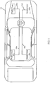
- FIG. 1 illustrates an example of vehicle 100 including Ethernet switch 102 for implementing FlexRay communications between FlexRay nodes 104a, 104b, 104c, and 104d over Ethernet links 106a, 106b, 106c, and 106d, in accordance with various aspects of the subject technology.
- FlexRay nodes 104a, 104b, 104c, and 104d may be ECUs used for engine control, transmission control, airbags, antilock braking, cruise control (e.g., adaptive cruise control), active suspension, drive-by-wire, electric power steering, audio systems, windows, doors, mirror adjustment, battery and recharging systems for hybrid/electric cars, lighting, power locks, and/or other functions.
- cruise control e.g., adaptive cruise control
- a FlexRay node having a FlexRay message to transmit may include an Ethernet adaptation module that converts the FlexRay message into an Ethernet data packet.
- This Ethernet data packet may be received over an Ethernet link (e.g., Ethernet link 106a) by Ethernet switch 102, which may then transmit the Ethernet data packet to one or more receiving FlexRay nodes (e.g., FlexRay nodes 104b, 104c, and 104d) over one or more Ethernet links (e.g., Ethernet links 106b, 106c, and 106d).
- the one or more receiving FlexRay nodes may each include Ethernet adaptation modules that convert the Ethernet data packet to the original FlexRay message.
- Ethernet switch 102 may implement preemption switching (e.g., using the Institute of Electrical and Electronics Engineers (IEEE) 802.1 Qbu proposed standard) and/or time-aware scheduling (e.g., using the IEEE 802.1Qbv proposed standard) to transmit higher priority messages (e.g., event-triggered data from a particular FlexRay node) before transmitting other lower priority messages, even if those lower priority messages were received by Ethernet switch 102 no later than the high priority messages.
- IEEE Institute of Electrical and Electronics Engineers
- time-aware scheduling e.g., using the IEEE 802.1Qbv proposed standard
- aspects of the subject technology provide for the low-latency Ethernet transmission of high priority FlexRay messages.
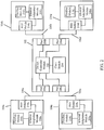
- FIG. 2 is a block diagram illustrating components of Ethernet switch 102 and FlexRay nodes 104a, 104b, 104c, and 104d, in accordance with various aspects of the subject technology.
- Ethernet switch 102 includes ports 206a, 206b, 206c, and 206d, switch controller module 202, and clock module 204, which are in communication with one another.
- FlexRay node 104a includes Ethernet adaptation module 208a, FlexRay module 210a, and physical layer (PHY) module 214a, which are in communication with one another.
- FlexRay node 104b includes Ethernet adaptation module 208b, FlexRay module 210b, and PHY module 214b.
- FlexRay node 104c includes Ethernet adaptation module 208c, FlexRay module 210c, and PHY module 214c.
- FlexRay node 104d includes Ethernet adaptation module 208d, FlexRay module 210d, and PHY module 214d.
- the modules may be implemented in software (e.g., subroutines and code).
- some or all of the modules may be implemented in hardware (e.g., an Application Specific Integrated Circuit (ASIC), a Field Programmable Gate Array (FPGA), a Programmable Logic Device (PLD), a controller, a state machine, gated logic, discrete hardware components, or any other suitable devices) and/or a combination of both. Additional features and functions of these modules according to various aspects of the subject technology are further described in the present disclosure.
- ASIC Application Specific Integrated Circuit
- FPGA Field Programmable Gate Array
- PLD Programmable Logic Device
- Ethernet switch 102 may facilitate the synchronization of timing for FlexRay nodes connected to Ethernet switch 102 (e.g., FlexRay nodes 104a, 104b, 104c, and 104d).
- clock module 204 includes logic, circuitry, and/or code for enabling Ethernet switch 102 to transmit and receive data packets according to timing cycles.
- Clock module 204 may generate a primary reference clock (e.g., from a free-running crystal oscillator) or receive the primary reference clock from another network component (e.g., another switch).
- Clock module 204 may provide the primary reference clock to switch controller module 202.
- Switch controller module 202 and/or a port may include a transceiver (e.g., a receiver and transmitter), a scrambler, a descrambler, one or more digital signal processing blocks, and/or other components for supporting communications with other network equipment.
- switch controller module 202 provides the primary reference clock received from clock module 204 to the FlexRay nodes connected to Ethernet switch 102 (e.g., via corresponding ports such as port 206a, 206b, 206c, and/or 206d) in order to synchronize the timing among these nodes.
- switch controller module 202 and/or clock module 204 may derive and/or generate a FlexRay reference cycle clock to synchronize timing for FlexRay nodes connected to Ethernet switch 102 using the IEEE 802.1AS standard, the IEEE 1588 standard, and/or other standards.
- a PHY module (e.g., PHY module 214a, 214b, 214c, or 214d) includes logic, circuitry, interfaces, and/or code for supporting communications with other network equipment.
- a PHY module may include a transceiver (e.g., a receiver and transmitter), a scrambler, a descrambler, one or more digital signal processing blocks, and/or other components for supporting communications with other network equipment.
- the PHY module may receive the primary reference clock from Ethernet switch 102 and provide the primary reference clock to a corresponding Ethernet adaptation module (e.g., Ethernet adaptation module 208a, 208b, 208c, or 208d).
- an Ethernet adaptation module includes logic, circuitry, and/or code for adapting FlexRay communications to Ethernet communications and vice versa.
- an Ethernet adaptation module provides the primary reference clock (received from a corresponding PHY module) to a corresponding FlexRay module (e.g., FlexRay module 210a, 210b, 210c, or 210d).
- a FlexRay module includes logic, circuitry, and/or code for generating FlexRay messages.
- the FlexRay module includes a FlexRay controller. Each FlexRay message includes a data frame and a frame ID that identifies a time slot (based on the primary reference clock) in which the data frame is scheduled to be transmitted.
- This time slot may either be a static time slot (e.g., a time slot in the static segment of a communication time cycle) or a dynamic time slot (e.g., a time slot in the dynamic segment of the communication time cycle).
- An Ethernet adaptation module may generate an Ethernet data packet based on a FlexRay message received from a corresponding FlexRay module. According to certain aspects, the Ethernet adaptation module may encapsulate a FlexRay message as an Ethernet data packet, thereby allowing the FlexRay message to be transmitted over an Ethernet link.
- a PHY module may receive the Ethernet data packet from a corresponding Ethernet adaptation module and provide the Ethernet data packet to Ethernet switch 102 over an Ethernet link (e.g., Ethernet link 106a, 106b, 106c, or 106d). According to certain aspects, the PHY module may transmit the Ethernet data packet during the time slot identified by a frame ID of a corresponding FlexRay message.
- a port of Ethernet switch 102 receives an Ethernet data packet from a respective FlexRay node (e.g., port 206a receives an Ethernet data packet from PHY module 214a of FlexRay node 104a over Ethernet link 106a, port 206b receives an Ethernet data packet from PHY module 214b of FlexRay node 104b over Ethernet link 106b, port 206c receives an Ethernet data packet from PHY module 214c of FlexRay node 104c over Ethernet link 106c, and/or port 206d receives an Ethernet data packet from PHY module 214d of FlexRay node 104d over Ethernet link 106d).
- the port may provide the received Ethernet data packet to switch controller module 202, which may route the Ethernet data packet to a destination via one or more other ports.
- clock module 204 may determine when switch controller module 202 should route the Ethernet data packet to its intended destination. Since a FlexRay message may include information regarding a desired time slot of a communication time cycle in which the message should be transmitted, switch controller module 202 may extract this timing information, and clock module 204 may determine an acceptable time (e.g., a transmit clock) to transmit the Ethernet data packet to its intended destination. Clock module 204 may determine the transmit clock using the primary reference clock that it generated (e.g., from a free-running crystal oscillator) or received from another network component (e.g., another switch). Switch controller module 202 may transmit an Ethernet data packet according to a corresponding transmit clock generated by clock module 204. The PHY module may receive the Ethernet data packet from Ethernet switch 102. The corresponding Ethernet adaptation module may extract the FlexRay message from the Ethernet data packet and provide the FlexRay message to the corresponding FlexRay module.
- a transmit clock e.g., a transmit clock
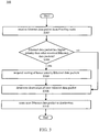
- FIG. 3 illustrates an example of method 300 for implementing FlexRay communications between FlexRay nodes 104a, 104b, 104c, and 104d over Ethernet links 106a, 106b, 106c, and 106d, in accordance with various aspects of the subject technology.
- Ethernet switch 102 may be used to implement method 300.
- method 300 may also be implemented by systems having other configurations.
- method 300 is described herein with reference to the examples of FIGS. 1 , 2 and 4 , method 300 is not limited to these examples.
- method 300 does not necessarily need to be performed in the order as shown. Based upon design preferences, it is understood that the order of method 300 may be rearranged.
- FlexRay node 104a intends to transmit a first Ethernet data packet (including a first FlexRay message that includes a first data frame and a first frame ID) to FlexRay node 104b.
- first data frame is event-triggered data
- first frame ID identifies a dynamic time slot for transmission of the first data frame.
- FlexRay node 104c intends to transmit a second Ethernet data packet (including a second FlexRay message that includes a second data frame and a second frame ID) to FlexRay node 104d.
- the second data frame is also event-triggered data, and thus, the second frame ID identifies a dynamic time slot for transmission of the second data frame.
- FlexRay nodes 104a and 104c may transmit the first Ethernet data packet and the second Ethernet data packet, respectively, to Ethernet switch 102, which receives these packets via ports 206a and 206c, respectively. Moreover, assume that Ethernet switch 102 receives the first Ethernet data packet no later than receiving the second Ethernet data packet. In other words, Ethernet switch 102 receives the second Ethernet data packet at the same time or later than the first Ethernet data packet is received (S302).
- switch controller module 202 is configured to determine whether the second Ethernet data packet has higher priority than the first Ethernet data packet for transmission (S304). For example, since the first frame data and the second frame data are event-triggered data (and therefore may occupy the same dynamic time slots), switch controller module 202 can determine which of these data frames (and corresponding Ethernet data packet) has priority for transmission. According to certain aspects, switch controller module 202 determines whether the second Ethernet data packet has higher priority than the first Ethernet data packet based on the first frame ID and the second frame ID. Switch controller module 202 may emulate the FlexRay prioritization process by giving higher priority to Ethernet data packets that are associated with lower frame IDs.
- switch controller module 202 may proceed with determining a destination of the next Ethernet data packet (e.g., the first Ethernet data packet) for transmission (S308). However, if the second Ethernet data packet is determined to have higher priority than the first Ethernet data packet (e.g., the second frame ID is less than the first frame ID), switch controller module 202 suspends routing of the first Ethernet data packet to allow the second Ethernet data packet to be transmitted (S306).
- switch controller module 202 determines a destination of the second Ethernet data packet (S308).
- the second FlexRay message from the second Ethernet data packet may include information regarding its intended destination.
- switch controller module 202 may determine the destination of the second Ethernet data packet by extracting the intended destination information from the second FlexRay message.
- the destination may be predetermined. For example, one or more nodes (e.g., FlexRay node 104b, 104c, and/or 104d) may be predetermined to receive all data packets originating from FlexRay node 104c.
- This predetermined destination may be provided to and/or stored in Ethernet switch 102.
- switch controller module 202 may determine the destination of the second Ethernet data packet by looking up the predetermined destination. As discussed above, the intended destination of the second Ethernet data packet is FlexRay node 104d. Thus, switch controller module 202 may determine that FlexRay node 104d is the destination of the second Ethernet data packet.
- the destination of the second Ethernet data packet is described as being determined after routing of the first Ethernet data packet is suspended, this destination may be determined at any time before the second Ethernet data packet is routed, such as immediately after the second Ethernet data packet is received, before the priority of the second Ethernet data packet is determined, before routing of the first Ethernet data packet is suspended, etc. In some aspects, the destination of the first Ethernet data packet may also be determined any time before the first Ethernet data packet is routed, even before the second Ethernet data packet is routed.
- switch controller module 202 routes the second Ethernet data packet to the determined destination via one or more corresponding ports (S310). For example, switch controller module 202 may route the second Ethernet data packet to FlexRay node 104d via port 206d. After the second Ethernet data packet has been routed, switch controller module 202 may resume routing of the first Ethernet data packet. In one or more implementations, switch controller module 202 may determine the intended destination of the first Ethernet data packet, which in this case is FlexRay node 104b, and route the first Ethernet data packet to FlexRay node 104b via port 206b.
- the second Ethernet data packet is described as being routed before the first Ethernet data packet (e.g., because the second Ethernet data packet has higher priority than the first Ethernet data packet), the second Ethernet data packet and the first Ethernet data packet may also be routed at the same time even though the second Ethernet data packet has higher priority than the first Ethernet data packet.
- switch controller module 202 may route the first Ethernet data packet and the second Ethernet data packet to their intended destinations at the same time (e.g., during the same transmission cycle) since these Ethernet data packets would not share the same Ethernet link for transmission.
- FlexRay bus status signaling may be propagated using Ethernet.
- This signaling may include FlexRay error messages.
- Switch controller module 202 may detect a FlexRay message error (e.g., an excessive cyclic redundancy check error, a local address not-reachable and/or not-listened-to error, etc.), and generate a corresponding Ethernet fault message based on the detected FlexRay message error.
- Switch controller module 202 may route the generated Ethernet fault message to the FlexRay node to which the error is applicable.
- the Ethernet adaptation module of this FlexRay node may receive the Ethernet fault message (via the corresponding PHY module), generate the corresponding FlexRay message error based on the received Ethernet fault message, and provide the FlexRay message error to the corresponding FlexRay module.
- the Ethernet adaptation module may also report cable faults (e.g., short, open, improper transmission line, etc.) to the FlexRay module.
- FlexRay communications are described above as being implemented using Ethernet switch 102, the FlexRay communications may also be implemented using a shared Ethernet bus operation (e.g., FlexRay nodes 104a, 104b, 104c, and 104d may transmit directly over a shared Ethernet link).
- a shared Ethernet bus operation may include the IEEE 802.3 Carrier-Sense, Multiple Access / Collision Detection (CSMA/CD) method, the master-slave timeslot access IEEE 802.3 Ethernet PON method, or variants thereof.
- CSMA/CD Carrier-Sense, Multiple Access / Collision Detection
- each FlexRay node may transmit and receive Ethernet data packets as described above, except that the transmission and receipt of the Ethernet data packets are over a single Ethernet link. Thus, all FlexRay nodes may listen to the transmissions occurring over the Ethernet link.
- each FlexRay node may monitor the Ethernet link during a dynamic time slot and inform a corresponding FlexRay module of whether the Ethernet link is free for transmission during the dynamic time slot. If so, a FlexRay node interested in transmitting a data frame during this time slot may do so. If the Ethernet link is not free for transmission (e.g., because a higher priority FlexRay node is transmitting during this time), a lower priority FlexRay node interested in transmitting may wait until a later transmission cycle to transmit its data frame.
- FIG. 4 is a block diagram illustrating components of controller 400, in accordance with various aspects of the subject technology.
- Controller 400 comprises processor module 404, storage module 410, input/output (I/O) module 408, memory module 406, and bus 402.
- Bus 402 may be any suitable communication mechanism for communicating information.
- Processor module 404, storage module 410, I/O module 408, and memory module 406 are coupled with bus 402 for communicating information between any of the modules of controller 400 and/or information between any module of controller 400 and a device external to controller 400.
- information communicated between any of the modules of controller 400 may include instructions and/or data.
- bus 402 may be a universal serial bus.
- bus 402 may provide Ethernet connectivity.
- processor module 404 may comprise one or more processors, where each processor may perform different functions or execute different instructions and/or processes. For example, one or more processors may execute instructions for implementing FlexRay communications using Ethernet, and one or more processors may execute instructions for input/output functions.
- Memory module 406 may be random access memory ("RAM") or other dynamic storage devices for storing information and instructions to be executed by processor module 404. Memory module 406 may also be used for storing temporary variables or other intermediate information during execution of instructions by processor 404. In some aspects, memory module 406 may comprise battery-powered static RAM, which stores information without requiring power to maintain the stored information. Storage module 410 may be a magnetic disk or optical disk and may also store information and instructions. In some aspects, storage module 410 may comprise hard disk storage or electronic memory storage (e.g., flash memory). In some aspects, memory module 406 and storage module 410 are both a machine-readable medium.
- RAM random access memory
- Memory module 406 may also be used for storing temporary variables or other intermediate information during execution of instructions by processor 404.
- memory module 406 may comprise battery-powered static RAM, which stores information without requiring power to maintain the stored information.
- Storage module 410 may be a magnetic disk or optical disk and may also store information and instructions. In some aspects, storage module 410 may comprise hard disk storage or
- Controller 400 may be coupled via I/O module 408 to a system control and management system (e.g., a vehicle central gateway), drive train system control unit, and/or a user interface, which may allow a user to communicate information and select commands to controller 400 as well as receive information from controller 400.
- a vehicle central gateway may provision bandwidth, log fault diagnostics, reset and recover actions, and log statistics.
- the user interface may be a monitor (e.g., liquid crystal display (LCD), a light emitting diode (LED) display, an organic light emitting diode (OLED) display, a flexible display, a flat panel display, a solid state display) for displaying information to a user.
- the user interface may also include, for example, a keyboard, a mouse, or any device with sensory feedback, visual feedback, auditory feedback, and/or tactile feedback coupled to controller 400 via I/O module 408 for communicating information and command selections to processor module 404.
- processor module 404 executes one or more sequences of instructions contained in memory module 406 and/or storage module 410.
- instructions may be read into memory module 406 from another machine-readable medium, such as storage module 410.
- instructions may be read directly into memory module 406 from I/O module 408, for example from a user via the user interface. Execution of the sequences of instructions contained in memory module 406 and/or storage module 410 may cause processor module 404 to perform methods to implement FlexRay communications using Ethernet.
- a computational algorithm for implementing FlexRay communications using Ethernet may be stored in memory module 406 and/or storage module 410 as one or more sequences of instructions.
- Information such as an Ethernet data packet, a FlexRay message, a destination, timing information, a FlexRay message error, an Ethernet fault message, and/or other information may be communicated from processor module 404 to memory module 406 and/or storage module 410 via bus 402 for storage.
- the information may be communicated from processor module 404, memory module 406, and/or storage module 410 to I/O module 408 via bus 402. The information may then be communicated from I/O module 408 to a user via the user interface.
- processors in a multi-processing arrangement may also be employed to execute the sequences of instructions contained in memory module 406 and/or storage module 410.
- hard-wired circuitry may be used in place of or in combination with software instructions to implement various aspects of the subject technology.
- aspects of the subject technology are not limited to any specific combination of hardware circuitry and software.
- machine-readable medium refers to any medium that participates in providing instructions to processor module 404 for execution. Such a medium may take many forms, including, but not limited to, non-volatile media and volatile media.
- Non-volatile media include, for example, optical or magnetic disks, such as storage module 410.
- Volatile media include dynamic memory, such as memory module 406.
- Machine-readable media or computer-readable media include, for example, floppy disk, a flexible disk, hard disk, magnetic tape, any other magnetic medium, a CD-ROM, DVD, any other optical medium, punch cards, paper tape, any other physical mediums with patterns of holes, a RAM, a PROM, an EPROM, a FLASH EPROM, any other memory chip or cartridge, or any other medium from which a processor can read.
- any specific order or hierarchy of blocks in the processes disclosed is an illustration of example approaches. Based upon design preferences, it is understood that the specific order or hierarchy of blocks in the processes may be rearranged, or that all illustrated blocks be performed. Any of the blocks may be performed simultaneously. In one or more implementations, multitasking and parallel processing may be advantageous. Moreover, the separation of various system components in the embodiments described above should not be understood as requiring such separation in all embodiments, and it should be understood that the described program components and systems can generally be integrated together in a single software product or packaged into multiple software products.
- the terms "receiver”, “computer”, “server”, “processor”, and “memory” all refer to electronic or other technological devices. These terms exclude people or groups of people.
- the terms “display” or “displaying” means displaying on an electronic device.
- the phrase "at least one of” preceding a series of items, with the term “and” or “or” to separate any of the items, modifies the list as a whole, rather than each member of the list (i.e., each item).
- the phrase "at least one of” does not require selection of at least one of each item listed; rather, the phrase allows a meaning that includes at least one of any one of the items, and/or at least one of any combination of the items, and/or at least one of each of the items.
- phrases “at least one of A, B, and C” or “at least one of A, B, or C” each refer to only A, only B, or only C; any combination of A, B, and C; and/or at least one of each of A, B, and C.
- a processor configured to analyze and control an operation or a component may also mean the processor being programmed to analyze and control the operation or the processor being operable to analyze and control the operation.
- a processor configured to execute code can be construed as a processor programmed to execute code or operable to execute code.
- a phrase such as "an aspect” does not imply that such aspect is essential to the subject technology or that such aspect applies to all configurations of the subject technology.
- a disclosure relating to an aspect may apply to all configurations, or one or more configurations.
- An aspect may provide one or more examples of the disclosure.
- a phrase such as an "aspect” may refer to one or more aspects and vice versa.
- a phrase such as an "embodiment” does not imply that such embodiment is essential to the subject technology or that such embodiment applies to all configurations of the subject technology.
- a disclosure relating to an embodiment may apply to all embodiments, or one or more embodiments.
- An embodiment may provide one or more examples of the disclosure.
- a phrase such an "embodiment” may refer to one or more embodiments and vice versa.
- a phrase such as a "configuration” does not imply that such configuration is essential to the subject technology or that such configuration applies to all configurations of the subject technology.
- a disclosure relating to a configuration may apply to all configurations, or one or more configurations.
- a configuration may provide one or more examples of the disclosure.
- a phrase such as a "configuration” may refer to one or more configurations and vice versa.
Landscapes
- Engineering & Computer Science (AREA)
- Computer Networks & Wireless Communication (AREA)
- Signal Processing (AREA)
- Health & Medical Sciences (AREA)
- Computing Systems (AREA)
- General Health & Medical Sciences (AREA)
- Medical Informatics (AREA)
- Small-Scale Networks (AREA)
Claims (9)
- FlexRay-Knoten (104) zum Durchführen von FlexRay-Kommunikationen unter Verwendung von Ethernet, wobei der FlexRay-Knoten umfasst:- ein Ethernet-Adaptionsmodul (208), das dafür ausgelegt ist, einen Bezugstakt zu empfangen, und- ein FlexRay-Modul (210), das dafür ausgelegt ist, basierend auf dem vom Ethernet-Adaptionsmodul empfangenen Bezugstakt eine FlexRay-Nachricht zu generieren, wobei die FlexRay-Nachricht einen Datenframe und eine Frame-Kennung (ID) umfasst, die basierend auf dem Bezugstakt, in dem der Datenframe zum Senden eingeplant wird, einen Zeitschlitz innerhalb eines Kommunikationszeitzyklus bestimmt, wobei die Frame-ID auf einer Priorität des FlexRay-Knotens basiert, und wobei- das Ethernet-Adaptionsmodul ferner dafür ausgelegt ist:- basierend auf der vom FlexRay-Modul empfangenen FlexRay-Nachricht ein Ethernet-Datenpaket zu generieren, und- das Ethernet-Datenpaket einem Sende-Empfangsgerät zuzuführen, um das Ethernet-Datenpaket über eine Ethernet-Verbindung an ein Ziel zu senden.
- FlexRay-Knoten nach Anspruch 1, wobei das Ethernet-Adaptionsmodul dafür ausgelegt ist, die FlexRay-Nachricht als das Ethernet-Datenpaket zu verkapseln.
- FlexRay-Knoten nach einem der vorhergehenden Ansprüche, wobei der FlexRay-Knoten ferner das Sende-Empfangsgerät umfasst, wobei das Sende-Empfangsgerät dafür ausgelegt ist, das Ethernet-Datenpaket an das Ziel zu senden.
- FlexRay-Knoten nach einem der vorhergehenden Ansprüche, wobei das Sende-Empfangsgerät dafür ausgelegt ist, den Bezugstakt über die Ethernet-Verbindung zu empfangen.
- FlexRay-Knoten nach einem der vorhergehenden Ansprüche, wobei das Sende-Empfangsgerät dafür ausgelegt ist, das Ethernet-Datenpaket während des Zeitschlitzes zu senden.
- FlexRay-Knoten nach einem der vorhergehenden Ansprüche, wobei die Ethernet-Verbindung einen gemeinsam genutzten Ethernet-Bus umfasst.
- FlexRay-Knoten nach einem der vorhergehenden Ansprüche, wobei das Ethernet-Adaptionsmodul dafür ausgelegt ist, eine Ethernet-Fehlermeldung zu empfangen.
- FlexRay-Knoten nach Anspruch 7, wobei das Ethernet-Adaptionsmodul dafür ausgelegt ist, basierend auf dem Empfang der Ethernet-Fehlermeldung dem FlexRay-Modul einen FlexRay-Nachrichtenfehler zuzuführen.
- FlexRay-Knoten nach Anspruch 1, wobei die Frame-ID ferner eine akzeptable Zeitdauer für einen Ethernet-Schalter bestimmt, um das über die Ethernet-Verbindung empfangene gesendete Ethernet-Datenpaket an das Ziel weiterzuleiten.
Applications Claiming Priority (3)
| Application Number | Priority Date | Filing Date | Title |
|---|---|---|---|
| US201261674834P | 2012-07-23 | 2012-07-23 | |
| US13/716,577 US9088514B2 (en) | 2012-07-23 | 2012-12-17 | Flexray communications using ethernet |
| EP13003106.5A EP2690826B1 (de) | 2012-07-23 | 2013-06-18 | Flexray-Kommunikationen über Ethernet |
Related Parent Applications (2)
| Application Number | Title | Priority Date | Filing Date |
|---|---|---|---|
| EP13003106.5A Division EP2690826B1 (de) | 2012-07-23 | 2013-06-18 | Flexray-Kommunikationen über Ethernet |
| EP13003106.5A Division-Into EP2690826B1 (de) | 2012-07-23 | 2013-06-18 | Flexray-Kommunikationen über Ethernet |
Publications (3)
| Publication Number | Publication Date |
|---|---|
| EP2863587A2 EP2863587A2 (de) | 2015-04-22 |
| EP2863587A3 EP2863587A3 (de) | 2015-07-08 |
| EP2863587B1 true EP2863587B1 (de) | 2017-08-09 |
Family
ID=48672335
Family Applications (2)
| Application Number | Title | Priority Date | Filing Date |
|---|---|---|---|
| EP13003106.5A Active EP2690826B1 (de) | 2012-07-23 | 2013-06-18 | Flexray-Kommunikationen über Ethernet |
| EP14004242.5A Active EP2863587B1 (de) | 2012-07-23 | 2013-06-18 | Flexray-Kommunikationen über Ethernet |
Family Applications Before (1)
| Application Number | Title | Priority Date | Filing Date |
|---|---|---|---|
| EP13003106.5A Active EP2690826B1 (de) | 2012-07-23 | 2013-06-18 | Flexray-Kommunikationen über Ethernet |
Country Status (5)
| Country | Link |
|---|---|
| US (2) | US9088514B2 (de) |
| EP (2) | EP2690826B1 (de) |
| KR (1) | KR101486071B1 (de) |
| CN (1) | CN103581061B (de) |
| TW (1) | TWI508500B (de) |
Families Citing this family (36)
| Publication number | Priority date | Publication date | Assignee | Title |
|---|---|---|---|---|
| DE102012215765A1 (de) * | 2012-09-05 | 2014-05-15 | Robert Bosch Gmbh | Gateway-Modul für ein Kommunikationssystem, Kommunikationssystem und Verfahren zur Übertragung von Daten zwischen Teilnehmern eines Kommunikationssystems |
| DE102012216689B4 (de) * | 2012-09-18 | 2017-05-04 | Continental Automotive Gmbh | Verfahren zur Überwachung eines Ethernet-basierten Kommunikationsnetzwerks in einem Kraftfahrzeug |
| CN103001722B (zh) * | 2012-11-23 | 2015-09-02 | 北京东土科技股份有限公司 | 一种基于时间触发以太网的数据传输方法及节点设备 |
| US9477276B2 (en) | 2013-06-13 | 2016-10-25 | Dell Products L.P. | System and method for switch management |
| KR101542016B1 (ko) * | 2014-09-17 | 2015-08-05 | 성균관대학교산학협력단 | 차량 내 이종 네트워크 도메인들 간의 동기화 게이트웨이 장치 및 동기화 방법 |
| CN104283752B (zh) * | 2014-10-17 | 2017-07-11 | 合肥工业大学 | 一种基于轮询调度器的FlexRay动态段消息调度方法 |
| KR101712370B1 (ko) | 2014-12-16 | 2017-03-06 | 주식회사 다산네트웍스 | 에러 패킷 분석을 지원하기 위한 이더넷 장치 및 시스템 |
| KR101622516B1 (ko) | 2015-04-20 | 2016-05-18 | 엘에스산전 주식회사 | 데이터 송수신 시스템 |
| JP6475096B2 (ja) * | 2015-06-11 | 2019-02-27 | 株式会社東海理化電機製作所 | 通信システム |
| CN104992550A (zh) * | 2015-07-22 | 2015-10-21 | 欧科佳(上海)汽车电子设备有限公司 | 基于以太网的总线仪表 |
| DE102015213845A1 (de) * | 2015-07-22 | 2017-01-26 | Robert Bosch Gmbh | Verfahren und Vorrichtung zur Validierung eines Zeitstempels einer Datenübertragung |
| CN105681145A (zh) * | 2016-02-29 | 2016-06-15 | 南京航空航天大学 | 一种基于FPGA的FlexRay通信模块 |
| EP3217614B1 (de) * | 2016-03-09 | 2018-09-19 | Mitsubishi Electric R&D Centre Europe B.V. | Multiplexverfahren für geplante rahmen in einem ethernet-schalter |
| CN105812464B (zh) * | 2016-03-10 | 2019-01-22 | 重庆大学 | 一种FlexRay总线的分布式加密存储方法及装置 |
| US10447606B2 (en) * | 2017-04-12 | 2019-10-15 | General Electric Company | Time-sensitive networking differentiation of traffic based upon content |
| DE102016221690A1 (de) * | 2016-11-04 | 2018-05-09 | Audi Ag | Verfahren zum Übertragen von Datenpaketen zwischen einem Ethernet und einem Bussystem in einem Kraftfahrzeug sowie Gatewayvorrichtung und Kraftfahrzeug |
| CN106603364B (zh) * | 2017-01-06 | 2019-11-01 | 上海理工大学 | 一种可用于实时传输的以太网通信方法 |
| DE102017203185B4 (de) | 2017-02-28 | 2018-09-06 | Audi Ag | Kraftfahrzeug mit einem in mehrere getrennte Domänen eingeteilten Datennetzwerk sowie Verfahren zum Betreiben des Datennetzwerks |
| CN107276845B (zh) * | 2017-06-06 | 2019-11-15 | 清华大学 | 一种轨道交通领域的具有容错功能的实时数据调度方法 |
| CN107276812B (zh) * | 2017-06-29 | 2021-06-04 | 北京广利核系统工程有限公司 | 一种核电站Level2层冗余设备的故障诊断装置、系统和方法 |
| JP6965767B2 (ja) * | 2018-01-23 | 2021-11-10 | 株式会社デンソー | 車載通信システム |
| CN110224909A (zh) * | 2018-03-02 | 2019-09-10 | 上海擎感智能科技有限公司 | 车载网络系统及汽车 |
| JP7001026B2 (ja) * | 2018-09-05 | 2022-01-19 | 株式会社デンソー | 車両用通信装置 |
| EP3694172B1 (de) * | 2019-02-07 | 2021-10-27 | AO Kaspersky Lab | System und verfahren zur steuerung des zugriffs auf ein cyber-physikalisches system |
| RU2726884C1 (ru) | 2019-02-07 | 2020-07-16 | Акционерное общество "Лаборатория Касперского" | Система и способ контроля доступа к кибер-физической системе |
| US11240061B2 (en) * | 2019-06-03 | 2022-02-01 | Progress Rail Locomotive Inc. | Methods and systems for controlling locomotives |
| CN115716455A (zh) * | 2019-09-12 | 2023-02-28 | 华为技术有限公司 | 实现汽车中电子控制功能的系统、方法以及汽车 |
| CN110933532A (zh) * | 2019-10-24 | 2020-03-27 | 北京邮电大学 | 基于帧抢占的tdm-pon移动前传光网络数据传输方法及装置 |
| KR102615478B1 (ko) * | 2019-10-24 | 2023-12-19 | 현대모비스 주식회사 | 자동차용 센서 통합 모듈 |
| CN111404697B (zh) * | 2020-03-31 | 2021-12-24 | 北京经纬恒润科技股份有限公司 | 一种车载以太网仿真板卡 |
| US11381421B2 (en) * | 2020-09-17 | 2022-07-05 | Ford Global Technologies, Llc | Using signal rating to identify security critical CAN messages and nodes for efficient implementation of distributed network security features |
| US11539714B2 (en) | 2020-09-17 | 2022-12-27 | Ford Global Technologies, Llc | Assigning categories for messages and symmetric key per category to localize the impact in case of key compromise |
| JP7547896B2 (ja) * | 2020-09-24 | 2024-09-10 | 株式会社デンソー | 車両用制御装置、車両用制御システム及びアクセス権管理プログラム |
| DE102020215329A1 (de) * | 2020-12-03 | 2022-06-09 | Continental Automotive Gmbh | Verfahren zum schnellen Flashen von Sensorknoten über ein Ethernetnetzwerk |
| EP4113909B1 (de) * | 2021-06-30 | 2025-10-08 | Aptiv Technologies AG | Lin-kommunikationsschaltung und verfahren zur kommunikation zwischen lin-bussen |
| DE102023116587A1 (de) * | 2023-06-23 | 2024-12-24 | Bayerische Motoren Werke Aktiengesellschaft | Steuervorrichtung und Verfahren zur Übermittlung von Steuerbefehlen |
Citations (1)
| Publication number | Priority date | Publication date | Assignee | Title |
|---|---|---|---|---|
| US20100254382A1 (en) * | 2007-12-21 | 2010-10-07 | Bayerische Motoren Werke Aktiengesellschaft | Communication System |
Family Cites Families (25)
| Publication number | Priority date | Publication date | Assignee | Title |
|---|---|---|---|---|
| JP3925234B2 (ja) * | 2002-02-18 | 2007-06-06 | ソニー株式会社 | データ通信システム、データ通信管理装置、および方法、並びにコンピュータ・プログラム |
| DE60314935T2 (de) | 2002-04-16 | 2007-12-20 | Robert Bosch Gmbh | Verfahren und Einheit zur Bitstromdekodierung |
| US7697549B2 (en) * | 2002-08-07 | 2010-04-13 | Extricom Ltd. | Wireless LAN control over a wired network |
| GB2396084B (en) * | 2002-12-03 | 2004-11-17 | Motorola Inc | System node and method for providing media arbitration |
| US7555017B2 (en) * | 2002-12-17 | 2009-06-30 | Tls Corporation | Low latency digital audio over packet switched networks |
| JP4401239B2 (ja) * | 2004-05-12 | 2010-01-20 | Necエレクトロニクス株式会社 | 通信メッセージ変換装置、通信方法及び通信システム |
| US7599377B2 (en) * | 2004-10-15 | 2009-10-06 | Temic Automotive Of North America, Inc. | System and method for tunneling standard bus protocol messages through an automotive switch fabric network |
| EP1758426A1 (de) * | 2005-08-24 | 2007-02-28 | Alcatel | Netzeinrichtung, Schnittstelleneinrichtung und Verfahren zum Austausch von Paketen |
| US7742505B2 (en) * | 2005-12-14 | 2010-06-22 | Adtran, Inc. | Systems and methods for enabling clock signal synchronization |
| JP4814950B2 (ja) * | 2006-09-29 | 2011-11-16 | 富士通セミコンダクター株式会社 | 送受信システム、ノード及び通信方法 |
| WO2008077320A1 (en) * | 2006-12-26 | 2008-07-03 | Hangzhou H3C Technologies Co., Ltd. | Method and device of ethernet switching |
| CN101843048B (zh) * | 2007-08-28 | 2014-06-11 | Tttech电脑技术股份公司 | 在网络中从分布式原理转换到主从原理的方法 |
| US9065673B2 (en) * | 2007-12-17 | 2015-06-23 | Broadcom Corporation | Method and system for a centralized vehicular electronics system utilizing ethernet with audio video bridging |
| WO2009124991A1 (en) * | 2008-04-10 | 2009-10-15 | Time-Critical Networks Ab | Calculating packet delay in a multihop ethernet network |
| US8179787B2 (en) * | 2009-01-27 | 2012-05-15 | Smsc Holding S.A.R.L. | Fault tolerant network utilizing bi-directional point-to-point communications links between nodes |
| WO2010116416A1 (ja) * | 2009-04-08 | 2010-10-14 | トヨタ自動車株式会社 | データ中継装置、及び当該装置で用いられるデータ中継方法 |
| US20100268841A1 (en) * | 2009-04-20 | 2010-10-21 | Texas Instruments Incorporated | Using higher layer information to facilitate coexistence in wireless networks |
| US20110130916A1 (en) * | 2009-12-01 | 2011-06-02 | Ise Corporation | Location Based Vehicle Data Logging and Diagnostic System and Method |
| EP2509263B1 (de) | 2009-12-02 | 2016-08-10 | Toyota Jidosha Kabushiki Kaisha | Datenkommunikationsnetzwerksystem |
| TW201121261A (en) * | 2009-12-10 | 2011-06-16 | Chung Shan Inst Of Science | Message conversion method, message conversion device, and message conversion system |
| JP2011131762A (ja) * | 2009-12-25 | 2011-07-07 | Hitachi Automotive Systems Ltd | データ中継用制御装置および車両制御システム |
| DE102010005658A1 (de) * | 2010-01-19 | 2011-07-21 | THALES Defence Deutschland GmbH, 75175 | Verbindungsmodul zum Anbinden mindestens eines Sensors, Aktors oder Effektors an ein Service Oriented Architecture- (SOA-) Netzwerk |
| TWI427973B (zh) * | 2010-04-13 | 2014-02-21 | Univ Nat Changhua Education | FlexRay發射器 |
| CN102014139B (zh) * | 2010-12-09 | 2013-02-27 | 北京交通大学 | 一种车用FlexRay总线与以太网的协议转换装置 |
| US8863256B1 (en) * | 2011-01-14 | 2014-10-14 | Cisco Technology, Inc. | System and method for enabling secure transactions using flexible identity management in a vehicular environment |
-
2012
- 2012-12-17 US US13/716,577 patent/US9088514B2/en active Active
-
2013
- 2013-06-18 EP EP13003106.5A patent/EP2690826B1/de active Active
- 2013-06-18 EP EP14004242.5A patent/EP2863587B1/de active Active
- 2013-06-26 TW TW102122732A patent/TWI508500B/zh not_active IP Right Cessation
- 2013-06-26 KR KR20130073658A patent/KR101486071B1/ko active Active
- 2013-06-28 CN CN201310268794.5A patent/CN103581061B/zh active Active
-
2015
- 2015-04-06 US US14/679,942 patent/US10462069B2/en active Active
Patent Citations (1)
| Publication number | Priority date | Publication date | Assignee | Title |
|---|---|---|---|---|
| US20100254382A1 (en) * | 2007-12-21 | 2010-10-07 | Bayerische Motoren Werke Aktiengesellschaft | Communication System |
Also Published As
| Publication number | Publication date |
|---|---|
| CN103581061B (zh) | 2017-04-12 |
| EP2690826A3 (de) | 2014-02-26 |
| EP2863587A2 (de) | 2015-04-22 |
| EP2690826A2 (de) | 2014-01-29 |
| EP2690826B1 (de) | 2015-08-12 |
| US20150229585A1 (en) | 2015-08-13 |
| KR101486071B1 (ko) | 2015-01-23 |
| KR20140012886A (ko) | 2014-02-04 |
| TWI508500B (zh) | 2015-11-11 |
| US20140022912A1 (en) | 2014-01-23 |
| US9088514B2 (en) | 2015-07-21 |
| TW201406109A (zh) | 2014-02-01 |
| US10462069B2 (en) | 2019-10-29 |
| EP2863587A3 (de) | 2015-07-08 |
| CN103581061A (zh) | 2014-02-12 |
Similar Documents
| Publication | Publication Date | Title |
|---|---|---|
| EP2863587B1 (de) | Flexray-Kommunikationen über Ethernet | |
| EP2690827B1 (de) | CAN-Kommunikationen über Ethernet | |
| US10678243B2 (en) | Systems and methods for scalable electrical engineering (EE) architecture in vehicular environments | |
| Navet et al. | In-vehicle communication networks-a historical perspective and review | |
| US10574348B2 (en) | Method for time synchronization between communication nodes in network | |
| JP7774641B2 (ja) | 時刻同期の検証 | |
| Talbot et al. | Comparision of fieldbus systems can, ttcan, flexray and lin in passenger vehicles | |
| CN105388858A (zh) | 网络中通信节点的操作方法 | |
| CN105306517A (zh) | 用车内时间同步报文提供车辆诊断黑盒服务的方法和设备 | |
| CN108093028B (zh) | 基于车辆网络中呈现时间再现内容的方法和装置 | |
| Umair et al. | Communication technologies and network protocols of automotive systems | |
| US20190305983A1 (en) | Method and apparatus for configuring backup path in vehicle network | |
| Cataldo | Ethernet Network in the Automotive field: Standards, possible approaches to Protocol Validation and Simulations | |
| HK1191773A (en) | Flexray communications using ethernet | |
| Manoj et al. | Automotive Networks: A Review | |
| HK1191772A (en) | Controller area network communications using ethernet | |
| Devi et al. | 2 Use of Communication | |
| Devi et al. | Use of Communication Protocols in Automotive Software Development Process | |
| Huang et al. | A Deterministic-Latency MAC Protocol for Future Automotive Ethernet | |
| CN121979060A (en) | Whole vehicle data fusion system and method | |
| Mischo et al. | Basic principles of networking | |
| Sedhumadhavan et al. | Design of FPGA based Flexray Communication Protocol for Superior Automotive Applications | |
| Simonot-Lion | Automotive Networked Embedded Systems |
Legal Events
| Date | Code | Title | Description |
|---|---|---|---|
| PUAI | Public reference made under article 153(3) epc to a published international application that has entered the european phase |
Free format text: ORIGINAL CODE: 0009012 |
|
| 17P | Request for examination filed |
Effective date: 20141216 |
|
| AC | Divisional application: reference to earlier application |
Ref document number: 2690826 Country of ref document: EP Kind code of ref document: P |
|
| AK | Designated contracting states |
Kind code of ref document: A2 Designated state(s): AL AT BE BG CH CY CZ DE DK EE ES FI FR GB GR HR HU IE IS IT LI LT LU LV MC MK MT NL NO PL PT RO RS SE SI SK SM TR |
|
| AX | Request for extension of the european patent |
Extension state: BA ME |
|
| PUAL | Search report despatched |
Free format text: ORIGINAL CODE: 0009013 |
|
| AK | Designated contracting states |
Kind code of ref document: A3 Designated state(s): AL AT BE BG CH CY CZ DE DK EE ES FI FR GB GR HR HU IE IS IT LI LT LU LV MC MK MT NL NO PL PT RO RS SE SI SK SM TR |
|
| AX | Request for extension of the european patent |
Extension state: BA ME |
|
| RIC1 | Information provided on ipc code assigned before grant |
Ipc: H04L 12/40 20060101AFI20150529BHEP |
|
| 17Q | First examination report despatched |
Effective date: 20150622 |
|
| RBV | Designated contracting states (corrected) |
Designated state(s): AL AT BE BG CH CY CZ DE DK EE ES FI FR GB GR HR HU IE IS IT LI LT LU LV MC MK MT NL NO PL PT RO RS SE SI SK SM TR |
|
| GRAP | Despatch of communication of intention to grant a patent |
Free format text: ORIGINAL CODE: EPIDOSNIGR1 |
|
| RIC1 | Information provided on ipc code assigned before grant |
Ipc: H04L 12/931 20130101ALI20170208BHEP Ipc: H04L 12/40 20060101AFI20170208BHEP |
|
| INTG | Intention to grant announced |
Effective date: 20170227 |
|
| RAP1 | Party data changed (applicant data changed or rights of an application transferred) |
Owner name: AVAGO TECHNOLOGIES GENERAL IP (SINGAPORE) PTE. LTD |
|
| GRAS | Grant fee paid |
Free format text: ORIGINAL CODE: EPIDOSNIGR3 |
|
| GRAA | (expected) grant |
Free format text: ORIGINAL CODE: 0009210 |
|
| AC | Divisional application: reference to earlier application |
Ref document number: 2690826 Country of ref document: EP Kind code of ref document: P |
|
| AK | Designated contracting states |
Kind code of ref document: B1 Designated state(s): AL AT BE BG CH CY CZ DE DK EE ES FI FR GB GR HR HU IE IS IT LI LT LU LV MC MK MT NL NO PL PT RO RS SE SI SK SM TR |
|
| REG | Reference to a national code |
Ref country code: GB Ref legal event code: FG4D |
|
| REG | Reference to a national code |
Ref country code: CH Ref legal event code: EP Ref country code: AT Ref legal event code: REF Ref document number: 917925 Country of ref document: AT Kind code of ref document: T Effective date: 20170815 |
|
| REG | Reference to a national code |
Ref country code: IE Ref legal event code: FG4D |
|
| REG | Reference to a national code |
Ref country code: DE Ref legal event code: R096 Ref document number: 602013024996 Country of ref document: DE |
|
| REG | Reference to a national code |
Ref country code: NL Ref legal event code: MP Effective date: 20170809 |
|
| REG | Reference to a national code |
Ref country code: LT Ref legal event code: MG4D |
|
| REG | Reference to a national code |
Ref country code: AT Ref legal event code: MK05 Ref document number: 917925 Country of ref document: AT Kind code of ref document: T Effective date: 20170809 |
|
| PG25 | Lapsed in a contracting state [announced via postgrant information from national office to epo] |
Ref country code: LT Free format text: LAPSE BECAUSE OF FAILURE TO SUBMIT A TRANSLATION OF THE DESCRIPTION OR TO PAY THE FEE WITHIN THE PRESCRIBED TIME-LIMIT Effective date: 20170809 Ref country code: AT Free format text: LAPSE BECAUSE OF FAILURE TO SUBMIT A TRANSLATION OF THE DESCRIPTION OR TO PAY THE FEE WITHIN THE PRESCRIBED TIME-LIMIT Effective date: 20170809 Ref country code: FI Free format text: LAPSE BECAUSE OF FAILURE TO SUBMIT A TRANSLATION OF THE DESCRIPTION OR TO PAY THE FEE WITHIN THE PRESCRIBED TIME-LIMIT Effective date: 20170809 Ref country code: HR Free format text: LAPSE BECAUSE OF FAILURE TO SUBMIT A TRANSLATION OF THE DESCRIPTION OR TO PAY THE FEE WITHIN THE PRESCRIBED TIME-LIMIT Effective date: 20170809 Ref country code: NL Free format text: LAPSE BECAUSE OF FAILURE TO SUBMIT A TRANSLATION OF THE DESCRIPTION OR TO PAY THE FEE WITHIN THE PRESCRIBED TIME-LIMIT Effective date: 20170809 Ref country code: SE Free format text: LAPSE BECAUSE OF FAILURE TO SUBMIT A TRANSLATION OF THE DESCRIPTION OR TO PAY THE FEE WITHIN THE PRESCRIBED TIME-LIMIT Effective date: 20170809 Ref country code: NO Free format text: LAPSE BECAUSE OF FAILURE TO SUBMIT A TRANSLATION OF THE DESCRIPTION OR TO PAY THE FEE WITHIN THE PRESCRIBED TIME-LIMIT Effective date: 20171109 |
|
| PG25 | Lapsed in a contracting state [announced via postgrant information from national office to epo] |
Ref country code: IS Free format text: LAPSE BECAUSE OF FAILURE TO SUBMIT A TRANSLATION OF THE DESCRIPTION OR TO PAY THE FEE WITHIN THE PRESCRIBED TIME-LIMIT Effective date: 20171209 Ref country code: BG Free format text: LAPSE BECAUSE OF FAILURE TO SUBMIT A TRANSLATION OF THE DESCRIPTION OR TO PAY THE FEE WITHIN THE PRESCRIBED TIME-LIMIT Effective date: 20171109 Ref country code: LV Free format text: LAPSE BECAUSE OF FAILURE TO SUBMIT A TRANSLATION OF THE DESCRIPTION OR TO PAY THE FEE WITHIN THE PRESCRIBED TIME-LIMIT Effective date: 20170809 Ref country code: ES Free format text: LAPSE BECAUSE OF FAILURE TO SUBMIT A TRANSLATION OF THE DESCRIPTION OR TO PAY THE FEE WITHIN THE PRESCRIBED TIME-LIMIT Effective date: 20170809 Ref country code: GR Free format text: LAPSE BECAUSE OF FAILURE TO SUBMIT A TRANSLATION OF THE DESCRIPTION OR TO PAY THE FEE WITHIN THE PRESCRIBED TIME-LIMIT Effective date: 20171110 Ref country code: PL Free format text: LAPSE BECAUSE OF FAILURE TO SUBMIT A TRANSLATION OF THE DESCRIPTION OR TO PAY THE FEE WITHIN THE PRESCRIBED TIME-LIMIT Effective date: 20170809 Ref country code: RS Free format text: LAPSE BECAUSE OF FAILURE TO SUBMIT A TRANSLATION OF THE DESCRIPTION OR TO PAY THE FEE WITHIN THE PRESCRIBED TIME-LIMIT Effective date: 20170809 |
|
| PG25 | Lapsed in a contracting state [announced via postgrant information from national office to epo] |
Ref country code: DK Free format text: LAPSE BECAUSE OF FAILURE TO SUBMIT A TRANSLATION OF THE DESCRIPTION OR TO PAY THE FEE WITHIN THE PRESCRIBED TIME-LIMIT Effective date: 20170809 Ref country code: CZ Free format text: LAPSE BECAUSE OF FAILURE TO SUBMIT A TRANSLATION OF THE DESCRIPTION OR TO PAY THE FEE WITHIN THE PRESCRIBED TIME-LIMIT Effective date: 20170809 Ref country code: RO Free format text: LAPSE BECAUSE OF FAILURE TO SUBMIT A TRANSLATION OF THE DESCRIPTION OR TO PAY THE FEE WITHIN THE PRESCRIBED TIME-LIMIT Effective date: 20170809 |
|
| REG | Reference to a national code |
Ref country code: DE Ref legal event code: R097 Ref document number: 602013024996 Country of ref document: DE |
|
| PG25 | Lapsed in a contracting state [announced via postgrant information from national office to epo] |
Ref country code: IT Free format text: LAPSE BECAUSE OF FAILURE TO SUBMIT A TRANSLATION OF THE DESCRIPTION OR TO PAY THE FEE WITHIN THE PRESCRIBED TIME-LIMIT Effective date: 20170809 Ref country code: SM Free format text: LAPSE BECAUSE OF FAILURE TO SUBMIT A TRANSLATION OF THE DESCRIPTION OR TO PAY THE FEE WITHIN THE PRESCRIBED TIME-LIMIT Effective date: 20170809 Ref country code: EE Free format text: LAPSE BECAUSE OF FAILURE TO SUBMIT A TRANSLATION OF THE DESCRIPTION OR TO PAY THE FEE WITHIN THE PRESCRIBED TIME-LIMIT Effective date: 20170809 Ref country code: SK Free format text: LAPSE BECAUSE OF FAILURE TO SUBMIT A TRANSLATION OF THE DESCRIPTION OR TO PAY THE FEE WITHIN THE PRESCRIBED TIME-LIMIT Effective date: 20170809 |
|
| PLBE | No opposition filed within time limit |
Free format text: ORIGINAL CODE: 0009261 |
|
| STAA | Information on the status of an ep patent application or granted ep patent |
Free format text: STATUS: NO OPPOSITION FILED WITHIN TIME LIMIT |
|
| 26N | No opposition filed |
Effective date: 20180511 |
|
| PG25 | Lapsed in a contracting state [announced via postgrant information from national office to epo] |
Ref country code: SI Free format text: LAPSE BECAUSE OF FAILURE TO SUBMIT A TRANSLATION OF THE DESCRIPTION OR TO PAY THE FEE WITHIN THE PRESCRIBED TIME-LIMIT Effective date: 20170809 |
|
| REG | Reference to a national code |
Ref country code: DE Ref legal event code: R082 Ref document number: 602013024996 Country of ref document: DE Representative=s name: BOSCH JEHLE PATENTANWALTSGESELLSCHAFT MBH, DE Ref country code: DE Ref legal event code: R081 Ref document number: 602013024996 Country of ref document: DE Owner name: AVAGO TECHNOLOGIES INTERNATIONAL SALES PTE. LT, SG Free format text: FORMER OWNER: AVAGO TECHNOLOGIES GENERAL IP (SINGAPORE) PTE. LTD., SINGAPORE, SG |
|
| REG | Reference to a national code |
Ref country code: CH Ref legal event code: PL |
|
| GBPC | Gb: european patent ceased through non-payment of renewal fee |
Effective date: 20180618 |
|
| REG | Reference to a national code |
Ref country code: BE Ref legal event code: MM Effective date: 20180630 |
|
| REG | Reference to a national code |
Ref country code: IE Ref legal event code: MM4A |
|
| PG25 | Lapsed in a contracting state [announced via postgrant information from national office to epo] |
Ref country code: LU Free format text: LAPSE BECAUSE OF NON-PAYMENT OF DUE FEES Effective date: 20180618 Ref country code: MC Free format text: LAPSE BECAUSE OF FAILURE TO SUBMIT A TRANSLATION OF THE DESCRIPTION OR TO PAY THE FEE WITHIN THE PRESCRIBED TIME-LIMIT Effective date: 20170809 |
|
| PG25 | Lapsed in a contracting state [announced via postgrant information from national office to epo] |
Ref country code: GB Free format text: LAPSE BECAUSE OF NON-PAYMENT OF DUE FEES Effective date: 20180618 Ref country code: IE Free format text: LAPSE BECAUSE OF NON-PAYMENT OF DUE FEES Effective date: 20180618 Ref country code: FR Free format text: LAPSE BECAUSE OF NON-PAYMENT OF DUE FEES Effective date: 20180630 Ref country code: LI Free format text: LAPSE BECAUSE OF NON-PAYMENT OF DUE FEES Effective date: 20180630 Ref country code: CH Free format text: LAPSE BECAUSE OF NON-PAYMENT OF DUE FEES Effective date: 20180630 |
|
| PG25 | Lapsed in a contracting state [announced via postgrant information from national office to epo] |
Ref country code: BE Free format text: LAPSE BECAUSE OF NON-PAYMENT OF DUE FEES Effective date: 20180630 |
|
| PG25 | Lapsed in a contracting state [announced via postgrant information from national office to epo] |
Ref country code: MT Free format text: LAPSE BECAUSE OF NON-PAYMENT OF DUE FEES Effective date: 20180618 |
|
| PG25 | Lapsed in a contracting state [announced via postgrant information from national office to epo] |
Ref country code: TR Free format text: LAPSE BECAUSE OF FAILURE TO SUBMIT A TRANSLATION OF THE DESCRIPTION OR TO PAY THE FEE WITHIN THE PRESCRIBED TIME-LIMIT Effective date: 20170809 |
|
| PG25 | Lapsed in a contracting state [announced via postgrant information from national office to epo] |
Ref country code: PT Free format text: LAPSE BECAUSE OF FAILURE TO SUBMIT A TRANSLATION OF THE DESCRIPTION OR TO PAY THE FEE WITHIN THE PRESCRIBED TIME-LIMIT Effective date: 20170809 |
|
| PG25 | Lapsed in a contracting state [announced via postgrant information from national office to epo] |
Ref country code: HU Free format text: LAPSE BECAUSE OF FAILURE TO SUBMIT A TRANSLATION OF THE DESCRIPTION OR TO PAY THE FEE WITHIN THE PRESCRIBED TIME-LIMIT; INVALID AB INITIO Effective date: 20130618 Ref country code: MK Free format text: LAPSE BECAUSE OF NON-PAYMENT OF DUE FEES Effective date: 20170809 Ref country code: CY Free format text: LAPSE BECAUSE OF FAILURE TO SUBMIT A TRANSLATION OF THE DESCRIPTION OR TO PAY THE FEE WITHIN THE PRESCRIBED TIME-LIMIT Effective date: 20170809 |
|
| PG25 | Lapsed in a contracting state [announced via postgrant information from national office to epo] |
Ref country code: AL Free format text: LAPSE BECAUSE OF FAILURE TO SUBMIT A TRANSLATION OF THE DESCRIPTION OR TO PAY THE FEE WITHIN THE PRESCRIBED TIME-LIMIT Effective date: 20170809 |
|
| PGFP | Annual fee paid to national office [announced via postgrant information from national office to epo] |
Ref country code: DE Payment date: 20250710 Year of fee payment: 13 |