EP2863187A2 - Durchflussmessverfahren und Vorrichtung - Google Patents
Durchflussmessverfahren und Vorrichtung Download PDFInfo
- Publication number
- EP2863187A2 EP2863187A2 EP20140189280 EP14189280A EP2863187A2 EP 2863187 A2 EP2863187 A2 EP 2863187A2 EP 20140189280 EP20140189280 EP 20140189280 EP 14189280 A EP14189280 A EP 14189280A EP 2863187 A2 EP2863187 A2 EP 2863187A2
- Authority
- EP
- European Patent Office
- Prior art keywords
- section
- max
- flow passage
- passage cross
- flow
- Prior art date
- Legal status (The legal status is an assumption and is not a legal conclusion. Google has not performed a legal analysis and makes no representation as to the accuracy of the status listed.)
- Granted
Links
- 238000000691 measurement method Methods 0.000 title description 15
- 238000000034 method Methods 0.000 claims abstract description 54
- 230000005540 biological transmission Effects 0.000 claims description 68
- 238000004364 calculation method Methods 0.000 claims description 38
- 239000012530 fluid Substances 0.000 claims description 28
- 238000005259 measurement Methods 0.000 abstract description 45
- 238000010586 diagram Methods 0.000 description 11
- 230000010354 integration Effects 0.000 description 6
- 230000000644 propagated effect Effects 0.000 description 5
- 238000004088 simulation Methods 0.000 description 4
- 238000012885 constant function Methods 0.000 description 3
- 238000002474 experimental method Methods 0.000 description 3
- 238000012360 testing method Methods 0.000 description 3
- 238000007796 conventional method Methods 0.000 description 2
- 230000003247 decreasing effect Effects 0.000 description 2
- 230000000694 effects Effects 0.000 description 2
- 239000007788 liquid Substances 0.000 description 2
- 238000013459 approach Methods 0.000 description 1
- 230000000052 comparative effect Effects 0.000 description 1
- 230000001419 dependent effect Effects 0.000 description 1
- 238000012545 processing Methods 0.000 description 1
- 238000007789 sealing Methods 0.000 description 1
- 230000009466 transformation Effects 0.000 description 1
- XLYOFNOQVPJJNP-UHFFFAOYSA-N water Substances O XLYOFNOQVPJJNP-UHFFFAOYSA-N 0.000 description 1
Images





Classifications
-
- G—PHYSICS
- G01—MEASURING; TESTING
- G01F—MEASURING VOLUME, VOLUME FLOW, MASS FLOW OR LIQUID LEVEL; METERING BY VOLUME
- G01F1/00—Measuring the volume flow or mass flow of fluid or fluent solid material wherein the fluid passes through a meter in a continuous flow
-
- G—PHYSICS
- G01—MEASURING; TESTING
- G01F—MEASURING VOLUME, VOLUME FLOW, MASS FLOW OR LIQUID LEVEL; METERING BY VOLUME
- G01F1/00—Measuring the volume flow or mass flow of fluid or fluent solid material wherein the fluid passes through a meter in a continuous flow
- G01F1/66—Measuring the volume flow or mass flow of fluid or fluent solid material wherein the fluid passes through a meter in a continuous flow by measuring frequency, phase shift or propagation time of electromagnetic or other waves, e.g. using ultrasonic flowmeters
- G01F1/667—Arrangements of transducers for ultrasonic flowmeters; Circuits for operating ultrasonic flowmeters
- G01F1/668—Compensating or correcting for variations in velocity of sound
-
- G—PHYSICS
- G01—MEASURING; TESTING
- G01F—MEASURING VOLUME, VOLUME FLOW, MASS FLOW OR LIQUID LEVEL; METERING BY VOLUME
- G01F1/00—Measuring the volume flow or mass flow of fluid or fluent solid material wherein the fluid passes through a meter in a continuous flow
- G01F1/05—Measuring the volume flow or mass flow of fluid or fluent solid material wherein the fluid passes through a meter in a continuous flow by using mechanical effects
-
- G—PHYSICS
- G01—MEASURING; TESTING
- G01F—MEASURING VOLUME, VOLUME FLOW, MASS FLOW OR LIQUID LEVEL; METERING BY VOLUME
- G01F1/00—Measuring the volume flow or mass flow of fluid or fluent solid material wherein the fluid passes through a meter in a continuous flow
- G01F1/66—Measuring the volume flow or mass flow of fluid or fluent solid material wherein the fluid passes through a meter in a continuous flow by measuring frequency, phase shift or propagation time of electromagnetic or other waves, e.g. using ultrasonic flowmeters
- G01F1/667—Arrangements of transducers for ultrasonic flowmeters; Circuits for operating ultrasonic flowmeters
-
- G—PHYSICS
- G01—MEASURING; TESTING
- G01F—MEASURING VOLUME, VOLUME FLOW, MASS FLOW OR LIQUID LEVEL; METERING BY VOLUME
- G01F15/00—Details of, or accessories for, apparatus of groups G01F1/00 - G01F13/00 insofar as such details or appliances are not adapted to particular types of such apparatus
- G01F15/02—Compensating or correcting for variations in pressure, density or temperature
Definitions
- the present invention relates to a method and apparatus for measuring a flow rate with a high degree of accuracy in a flow passage having difficulty in sufficiently achieving flow-straightening, typically in a liquid rocket engine or other ground testing facilities, and the like.
- a volume flow rate can be defined as a volume of a fluid flowing through a flow passage cross-section within a time unit.
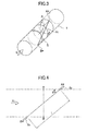
- a flow rate of a fluid flowing through a flow passage pipe arrangement 1 illustrated in FIG. 1 is represented as an integrated value of normal-directional components with respect to a flow passage cross-section of flow velocities at respective points on the flow passage cross-section, as follows:
- S represents a flow passage cross-section, wherein a position in the flow passage cross-section S is represented by (x, y).
- v z represents a normal-directional (z-directional) component of a flow velocity of the fluid with respect to the flow passage cross-section S
- v z (x, y) represents a normal-directional component at a position (x, y) of a flow velocity of the fluid at the position (x, y) on the flow passage cross-section S.
- y min (x) and y max (x) represent, respectively, a minimum value and a maximum value of the y-coordinate when the x-coordinate is fixed on the flow passage cross-section S
- x min and x max represent, respectively, a minimum value and a maximum value of the x-coordinate on the flow passage cross-section S.
- the flow passage cross-section S 1 is a plane orthogonal to an axis of the flow passage pipe arrangement 1, but even if the flow passage cross-section is inclined with respect to the axis, or is a curved surface, the flow rate can be represented by the above Formulas (1) to (3).
- V z (x i ) represents an average of values of v z (x, y) for respective points (x, y), on a region in the flow passage cross-section S in which the x-coordinate is equal to x i , namely on a line segment AB ( FIG. 2 ), and the V z (x i ) can be measured by, for example, an ultrasonic wave method.
- an ultrasonic element 2a configured to transmit an ultrasonic wave from the point A* and an ultrasonic element 2b configured to transmit an ultrasonic wave from the point B* are disposed on the flow passage pipe arrangement 1, to measure a propagation time of the ultrasonic wave transmitted from the ultrasonic element 2a until it is received by the ultrasonic element 2b, and a propagation time of the ultrasonic wave transmitted from the ultrasonic element 2b until it is received by the ultrasonic element 2a.
- this average value can be used as a value of V z (x i ).
- V z (x i ) can be measured at discrete positions.
- the pairs of ultrasonic elements on the flow passage pipe arrangement in a number corresponding to the number of x i points to be measured. In this case, however, there is a limit on the number of measurement points which can be arranged, and thus it is necessary to use a calculation technique capable of maintaining good accuracy even under a small number of measurement points.
- a method for deriving an approximate value of the flow rate Q represented by the Formula (1), from the discretely measured flow velocities, by Gaussian quadrature (Gauss-Legendre type, Chebyshev type, and Lobatto type) is disclosed in the Patent Document 2.
- the method disclosed in the Patent Document 2 is configured to determine an approximate value Q N of the flow rate Q by the following Formula, using Gaussian quadrature under a condition that an integrand is set to V z (x)L(x) and a weighting function is set to 1 (constant):
- x i and w i represent, respectively, a node and a coefficient of the Gaussian quadrature.
- the Patent Documents 3 and 4 disclose a method for deriving an approximate value of flow rate of a fluid flowing through a flow passage of a circular pipe having a radius R, from a discretely measured flow velocities.
- the weighting function is set as follows: 1 - x R 2 and on an assumption that the integrand is set to 2RV z (x)
- the nodes x i and the coefficients w i are calculated in accordance with Gaussian quadrature (Gauss-Chebyshev type).
- the flow velocity distribution itself is included in the integrand.
- a higher-order quadrature namely, a larger number of measurement points
- the present invention provides a method for measuring a flow rate Q of a fluid flowing through a flow passage, the flow rate Q being represented by the following Formula:
- V z x ⁇ y min x y max x ⁇ dy ⁇ ⁇ z x y y max x - y min x
- x y max x - y min x
- S represents a flow passage cross-section, wherein a position within the flow passage cross-section S is represented as (x, y);
- v z represents a normal-directional (z-directional) component with respect to the flow passage cross-section S of a flow
- the method of the present invention is characterized by formulating a weighting function V z0 (x)L(x) using an estimated flow velocity distribution on the flow passage cross-section S (which may be preliminarily derived by a theoretic calculation, a simulation, a preliminary experiment, or the like), and determining the approximate value of the flow rate by Gaussian quadrature.
- the integrand is expressed as: V z x i V z ⁇ 0 x i This represents a ratio of an average of values of actual flow velocity distribution to an average of values of the estimated flow velocity distribution for a certain x-coordinate.
- the accuracy of approximation is increased because the integrand becomes closer to a constant function.
- V' z0 (x) obtained by modifying the V z0 (x) with an appropriate offset function V z1 (x).
- the present invention provides a method for measuring a flow rate Q of a fluid flowing through a flow passage, the flow rate Q being represented by the Formulas (9) to (11), the method comprising the steps of:
- This method is based on an idea of using the offset function V z1 (x) to offset respective zero-points of V z0 (x) and V z (x) to thereby introduce V' z0 (x) and V' z (x), and then using them to apply Gaussian quadrature to a flow rate Q' obtained based on offset zero-points, as described below.
- V z1 (x) is preferably selected to allow V' z0 (x) to be always zero or more on the flow passage cross-section S, or to be always zero or less on the flow passage cross-section S.
- the node x i can be implemented in the integral interval as a corollary of the principle of Gaussian quadrature.
- the present invention further provides a flow rate measurement method, comprising the steps of: determining the approximate value Q N according to the method provided by the present invention as described above; and estimating an error range of the approximate value Q N based on the following Formula using a second approximate value Q SUB that is less reliable than the approximate value Q N : if Q SUB ⁇ Q N , Q SUB - Q N 2 ⁇ Q - Q N if Q SUB > Q N , Q SUB - Q N 2 > Q - Q N As described below, this method makes it possible to estimate an error of the approximate value Q N .
- the term second approximate value Q SUB which is "less reliable than the approximate value Q N" means an approximate value which is assumed to have an error greater than that of the approximate value Q N and which is determined by, for example, decreasing the number of measurement points N when using the method of the present invention, or, as described below, by uniformly replacing values of the integrand of the Gaussian quadrature with a maximum or minimum value thereof, instead of individually calculating the integrand of the Gaussian quadrature for respective nodes x i .
- the present invention further provides an apparatus for measuring a flow rate Q of a fluid flowing through a flow passage, the flow rate Q being represented by the Formulas (9) to (11), the apparatus comprising: a Gaussian quadrature operation section for determining a node x i and a coefficient w i for Gaussian quadrature [where i represents a natural number of 1 to N (where N represents an arbitrary natural number equal to or greater than 1)], using a weighting function V z0 (x) L(x) represented by the Formulas (12) and (13), where v z0 (x, y) represents an estimate value of a normal-directional component of a flow velocity at each position (x, y) within the flow passage cross-section S; a V z (x i ) determining section for determining V z (x i ) for each node x i determined by the Gaussian quadrature operation section; a V z0 (x i ) determining section for determining V z0 (
- the present invention further provides an apparatus for measuring a flow rate Q of a fluid flowing through a flow passage, the flow rate Q being represented by the Formulas (9) to (11), the apparatus comprising: a Gaussian quadrature operation section for determining a node x i and a coefficient w i for Gaussian quadrature [where i represents a natural number of 1 to N (where N represents an arbitrary natural number equal to or greater than 1)], using a weighting function V' z0 (x) L(x) represented by the Formula (18), using V' z0 (x) represented by the Formulas (16), (17) using an offset function V z1 (x), where v z0 (x, y) represents an estimate value of a normal-directional component of a flow velocity at each position (x, y) on the flow passage cross-section S; a V z (x i ) determining section for determining V z (x i ) for each node x i determined by the Gaussian quadrature operation
- the Gaussian quadrature operation section is preferably configured to use the V z1 (x) selected to allow V' z0 (x) to be always zero or more in the flow passage cross-section S, or to be always zero or less in the flow passage cross-section S.
- V z1 (x) selected to allow V' z0 (x) to be always zero or more in the flow passage cross-section S, or to be always zero or less in the flow passage cross-section S.
- V z1 (x) selected to allow V' z0 (x) to be always zero or more in the flow passage cross-section S, or to be always zero or less in the flow passage cross-section S.
- the V z (x i ) determining section may be configured to comprise:
- the above apparatus provided by the present invention may further comprise an error range estimating section for estimating an error range of the approximate value Q N based on the Formula (22), using a second approximate value Q SUB that is less reliable than the approximate value Q N .
- the present invention it is possible to formulate Gaussian quadrature optimal to a given flow velocity distribution. This makes it possible to accurately measure a flow rate under a small number of measurement points.
- the method and apparatus of the present invention is particularly effective for flow velocity distribution of unstraightened and distorted flow rate distribution.
- the integrand is not the flow velocity distribution itself, but represents a ratio of an actual flow velocity distribution with respect to an estimated flow velocity distribution. If a certain degree of probability of flow velocity distribution can be estimated in advance, the integrand becomes closer to a constant function even under a condition of significantly distorted flow velocity distribution and the like, so that it is possible to obtain a highly accurate approximate value of the flow rate.
- the error range estimation technique taught by the present invention it becomes possible to guess uncertainty of the actually measured flow rate (corresponding to an approximate error range of the integration) in a simplified manner. This makes it possible to evaluate the uncertainty of flow rate caused by an integration error without necessarily performing a comparison to a reference instrument. Of course, however, it is more secure to perform a comparison testing to the reference instrument if possible.
- This error range estimation technique is also applicable to a conventional art.
- a flow rate measurement method and a flow rate measurement apparatus of the present invention are not limited to the specific aspects described below, but are modifiable within a scope of the present invention.
- a flow rate of a fluid flowing through a flow passage of a circular pipe having a radius 1 is measured, but it is also possible to measure a flow rate of a fluid flowing through any other flow passage according to the present invention.
- the integral interval of Gaussian quadrature is deemed as [-1, 1].
- a system (a propagation time difference system) is used in which two ultrasonic elements are placed for every measurement point on the ow passage pipe arrangement, and a flow rate is determined from a difference in propagation times of the ultrasonic wave propagated in both directions between the ultrasonic elements.
- a Pulse Doppler system suitable for opaque liquid.
- the flow rate Q is measured as a volume flow rate, but alternatively, it is also possible to derive a mass flow rate by, for example, multiplying the measured volume flow rate by a density. Such a measurement of mass flow rate necessarily involves a measurement of volume flow rate, meaning that it falls within a technical scope of the present invention.
- circuits illustrated in FIG. 5 and 8 may be physically-isolated separate circuits, or conceptual and functional sections bearing each function in one circuit. Each circuit may comprise a plurality of circuits.
- a V' z0 (x i ), V z1 (x i ), Q z0 , Q z1 calculation circuit in FIG. 8 may be a circuit group consisting of a circuit for calculating V' z0 (x i ), a circuit for calculating V z1 (x i ), a circuit for calculating Q z0 , and a circuit for calculating Q z1 .
- Respective processing performed to implement the present invention can be arbitrarily distributed to any one or more elements.
- Gaussian quadrature is a collective term referring to a general numerical integration method determining the finite number of nodes and coefficients by using a weighting function and performed as a polynomial approximation by using the nodes and coefficients. Specific values of the nodes and coefficients are dependent on a condition such as the weighting function.
- the Gaussian quadrature in such a general sense will be described below.
- the approximate value Q N shown in the above Formula (14) can be obtained through a following procedure in the above Gaussian quadrature: setting the weighting function w(x) to V z0 (x)L(x) (Formula (12)); determining the nodes x i and the coefficients w i using the Formulas (23) to (27); setting the integrand f(x) to V z (x)/V z0 (x) (Formula (15)); and performing an arithmetic operation with the Formula (28).
- An approximate value Q N of the flow rate Q that is deemed to be most probable is derived according to a flow rate measurement method in one embodiment of the present invention.
- an approximate value Q SUB that is less reliable than Q N namely an approximate value Q SUB presumed to satisfy the following formula is derived by, for example, decreasing the number of measurement points utilized, and then using the flow rate measurement method of the present invention or any other methods: Q - Q N ⁇ Q - Q SUB
- the error range of Q N can be estimated as: if Q SUB ⁇ Q N , Q SUB - Q N 2 ⁇ Q - Q N if Q SUB > Q N , Q SUB - Q N 2 > Q - Q N
- the flow rate measurement apparatus in FIG. 5 comprises: a Gaussian quadrature operational circuit; at least one pair of ultrasonic elements 2a, 2b placed on the flow passage pipe arrangement 1, an ultrasonic wave transmission and receipt circuit; an ultrasonic wave transmission and receipt signal recording circuit; a flow velocity calculation circuit; a V z0 (x i ) calculation circuit; a Q N determination circuit; and, optionally, an error range estimation circuit.
- a V z (x i ) determining section is provided by the at least one pair of ultrasonic elements 2a, 2b, the ultrasonic wave transmission and receipt circuit, the ultrasonic wave transmission and receipt signal recording circuit and the flow velocity calculation circuit among these elements.
- an estimate value v z0 (x, y) of a normal-directional component of the flow velocity at each position (x, y) on the flow passage cross-section is input as an estimated flow velocity distribution.
- the normal direction (z-direction) corresponds to the axial direction, so that an estimate value v z0 (x, y) of the axial flow velocity at each position (x, y) on the flow passage cross-section S 1 is input as the estimated flow velocity distribution.
- the ultrasonic elements 2a, 2b are a pair of ultrasonic elements placed at an angle in an opposed relation on the flow passage pipe arrangement 1, as already described with reference to FIG. 4 .
- points A, B on the flow passage cross-section each corresponding to a respective one of a maximum value and a minimum value of the y-coordinate are determined as illustrated in FIG. 2 . Then, as illustrated in FIG.
- the pair of ultrasonic elements 2a, 2b are installed at respective position capable of performing transmission and receipt of the ultrasonic wave between A* and B*. That is, N sets of pair of ultrasonic elements 2a, 2b are placed.
- the ultrasonic wave transmission and receipt circuit is a circuit operable to transmit an ultrasonic wave transmission and receipt-instructing signal instructing a transmission and receipt of the ultrasonic wave to the ultrasonic elements 2a, 2b, and receive the ultrasonic signal received by the ultrasonic elements 2a, 2b, as well as transmit an ultrasonic wave transmission and receipt-indicative signal indicative of the transmission and receipt of the ultrasonic wave to the ultrasonic wave transmission and receipt signal recording circuit.
- the ultrasonic wave transmission and receipt signal recording circuit is a circuit operable to record the ultrasonic wave transmission and receipt-indicative signal transmitted from the ultrasonic wave transmission and receipt circuit.
- a signal indicative of t 1 , t 2 in the Formula (4) is transmitted from the ultrasonic wave transmission and receipt circuit and is recorded in the ultrasonic wave transmission and receipt signal recording circuit.
- the flow velocity calculation circuit is a circuit operable to receive the ultrasonic wave transmission and receipt-indicative signal from the ultrasonic wave transmission and receipt signal recording circuit, and perform an arithmetic operation on the signal to calculate V z (x i ) for each node x i .
- the flow velocity calculation circuit receives a signal indicative of t 1 , t 2 in the Formula (4) from the ultrasonic wave transmission and receipt signal recording circuit, calculatingly determines an average of values of v z (x, y) based on the Formula (4), and outputs the average value as V z (x i ).
- L and ⁇ (theta) in the Formula (4) shall be geometrically calculated by, for example, the Gaussian quadrature calculation circuit along with the node x i and the coefficient w i , and input to the flow velocity calculation circuit.
- the V z0 (x i ) calculation circuit calculatingly determines V z0 (x i ) using the estimated flow velocity distribution for each node x i determined by the Gaussian quadrature operation section. Since y min (x), y max (x) corresponding to each x-coordinate are determined by a shape of the flow passage cross-section, they can be preliminarily input to the V z0 (x i ) calculation circuit.
- the node x i is input from the Gaussian quadrature operation section.
- the v z0 (x, y) may be preliminarily input, or may be input from the Gaussian quadrature operation section.
- the Q N determination circuit is a circuit operable to receive inputs, from each of the operation and calculation circuits, of the coefficient w i determined by the Gaussian quadrature operational circuit, V z (x i ) determined by the flow velocity calculation circuit, and V z0 (x i ) determined by the V z0 (x i ) calculation circuit, and to calculatingly determine the approximate value Q N of the flow rate according to the Formula (14) using the above inputs.
- the error range estimation circuit is a circuit operable to receive an input of Q N from the Q N determination circuit and an input of the approximate value Q SUB that is less reliable than Q N from the Q N determination circuit or any other external circuit etc. (not illustrated) to estimate the error range according to the Formula (36).
- the estimated value v z0 (x, y) is input to the Gaussian quadrature operational circuit.
- the Gaussian quadrature operational circuit formulates the following weighting function from the input value v z0 (x, y), and determines the node x i and the coefficient w i according to the above described Gaussian quadrature.
- the transmission and receipt points A 1 * through A 3 *, B 1 * through B 3 * of the ultrasonic wave are determined ( FIG. 7 ).
- the points A 1 * through A 3 * and B 1 * through B 3 * are determined by determining points A 1 through A 3 and B 1 through B 3 for the nodes x 1 through x 3 in the manner as illustrated in FIG. 2 (the points A, B in FIG. 2 obtained by setting the point x i in FIG. 2 to a node x i are determined as the points A 1 , B 1 , the points A, B in FIG. 2 obtained by setting the point x i in FIG.
- Each of three pairs of ultrasonic elements 2a, 2b is placed at a position capable of performing transmission and receipt of the ultrasonic wave between each of A 1 * and B 1 *, A 2 * and B 2 *, and A 3 * and B 3 *.
- the placement of the ultrasonic elements can be performed by an optional actuator etc.
- the ultrasonic wave transmission and receipt circuit transmits the ultrasonic wave transmission and receipt-instructing signal to the three pairs of ultrasonic elements 2a, 2b.
- the three pairs of ultrasonic elements 2a, 2b bi-directionally transmit and receive the ultrasonic wave each between A 1 * and B 1 *, A 2 * and B 2 *, and A 3 * and B 3 * and the ultrasonic signal received by each ultrasonic element is transmitted to the ultrasonic wave transmission and receipt circuit.
- the ultrasonic wave transmission and receipt circuit measures, from the received ultrasonic signal, the propagation times t 1 , t 2 for each direction in each transmission and receipt passage, and transmits the propagation times to the ultrasonic wave transmission and receipt signal recording circuit as the ultrasonic wave transmission and receipt-indicative signal.
- the ultrasonic wave transmission and receipt signal recording circuit records the propagation times t 1 , t 2 for each direction in each transmission and receipt passage.
- the flow velocity calculation circuit receives the propagation times t 1 , t 2 from the ultrasonic wave transmission and receipt signal recording circuit, and calculates V z (x 1 ) through V z (x 3 ) for the nodes x 1 through x 3 according to the Formula (4).
- V z0 (x i ) calculation circuit calculatingly determines V z0 (x 1 ) through V z0 (x 3 ) for the nodes x 1 through x 3 using the estimated flow velocity distribution of the Formula (41) (In this case, ⁇ (square root of)(1 - x 2 ), and ⁇ (square root of)(1 - x 2 ).).
- the Q N determination circuit calculatingly determines the approximate value Q 3 of the flow rate according to the Formula (14) using the coefficients w 1 through w 3 determined by the Gaussian quadrature operational circuit, V z (x 1 ) through V z (x 3 ) determined by the flow velocity calculation circuit, and V z0 (x 1 ) through V z0 (x 3 ) determined by the V z0 (x i ) calculation circuit.
- the error range estimation circuit receives an input of Q 3 from the Q N determination circuit and an input of the approximate value Q SUB that is less reliable than Q N from the Q N determination circuit or any external circuit etc., to estimate the error range according to the Formula (36).
- the approximate value Q SUB may be an approximate value of the flow rate determined for N other than 3 using the above each circuit, or may be an approximate value of the flow rate determined according to any method different from the present invention.
- the technique of the present invention is more advantageous in most cases.
- the flow velocity distribution is closer to v z0 (x, y), the effect is larger.
- This method is based on an idea of using an appropriate function V z1 (x) to offset the zero-points of V z0 (x), V z (x) as the following Formulas (43) and (44), and selecting V z1 (x) particularly in such a manner as to allow V' z0 (x) to be always zero or more in the flow passage cross-section S, or to be always zero or less in the flow passage cross-section S, thereby to keep the sign of the weighting function to be constant:
- V z ⁇ 0 ⁇ x V z ⁇ 0 x + V z ⁇ 1 x
- V z ⁇ x V z x + Q N Q z ⁇ 0 ⁇ V z ⁇ 1 x
- the following formula is applied.
- the approximate value Q N can be determined by: determining the node x i and coefficient w i of Gaussian quadrature using the weighting function V' z0 (x)L(x) obtained based on an offset zero-point; determining V z (x i ) through the ultrasonic wave measurement or the like as described above for the determined measurement points x i ; calculatingly determining each of V' z0 (x i ), V z1 (x i ), Q z0 and Q z1 according to the definitional formulas; and substituting these values into the Formula (52).
- FIG. 8 One example of an apparatus capable of performing the flow rate measurement method of the present invention described in the second embodiment is illustrated in FIG. 8 .
- a V' z0 (x i ), V z1 (xi), Q z0 , Q z1 calculation circuit is used as substitute for the V z0 (x i ) calculation circuit in the apparatus illustrated in FIG. 5 .
- the structure and operation of the apparatus in FIG. 8 will be described below, in which an explanation of the same structure and operation as in the apparatus in FIG. 5 will be omitted.
- the flow rate measurement apparatus in FIG. 8 comprises: a Gaussian quadrature operational circuit; at least one pair of ultrasonic elements 2a, 2b placed on the flow passage pipe arrangement 1, an ultrasonic wave transmission and receipt circuit; an ultrasonic wave transmission and receipt signal recording circuit; a flow velocity calculation circuit; a V' z0 (x i ), V z1 (x i ), Q z0 , Q z1 calculation circuit; a Q N determination circuit, and, optionally, an error range estimation circuit.
- a V z (x i ) determining section is provided by the at least one pair of ultrasonic elements 2a, 2b, the ultrasonic wave transmission and receipt circuit, the ultrasonic wave transmission and receipt signal recording circuit and the flow velocity calculation circuit among these elements.
- an estimate value v z0 (x, y) of a normal-directional component of the flow velocity at each position (x, y) in the flow passage cross-section is input as an estimated flow velocity distribution, and preferably (although not necessary), an offset function V z1 (x) is input which is selected in such a manner as to allow V' z0 (x) represented by the Formula (16) to be always zero or more in the flow passage cross-section S, or to be always zero or less in the flow passage cross-section S.
- the ultrasonic elements 2a, 2b may be the same elements as described in relation to the apparatus in FIG. 5 .
- Each of the ultrasonic wave transmission and receipt circuit, the ultrasonic wave transmission and receipt signal recording circuit and the flow velocity calculation circuit may also be the same circuit as described in relation to the apparatus in FIG. 5 .
- the V' z0 (x i ), V z1 (x i ), Q z0 , Q z1 calculation circuit is a circuit operable to calculate V' z0 (x i ) and V z1 (x i ) for each node x i determined by the Gaussian quadrature operation section and calculatingly determine Q z0 and Q z1 .
- the node x i is input from the Gaussian quadrature operation section.
- the v z0 (x, y) may be preliminarily input, or may be input from the Gaussian quadrature operation section.
- the Q N determination circuit is a circuit operable to receive inputs, fro each of the operation and calculation circuits, of the coefficient w i determined by the Gaussian quadrature operational circuit, V z (x i ) determined by the flow velocity calculation circuit, and V' z0 (x i ), V z1 (x i ), Q z0 and Q z1 determined by the V' z0 (x i ), V z1 (x i ), Q z0 , Q z1 calculation circuit, and calculatingly determine the approximate value Q N of the flow rate according to the Formula (21) using the inputs.
- the arithmetic operation performed by each circuit is typically performed using a calculator etc.
- the error range estimation circuit is a circuit operable to receive an input of Q N from the Q N determination circuit and an input of the approximate value Q SUB that is less reliable than Q N from the Q N determination circuit or any other external circuit etc. to estimate the error range according to the Formula (36).
- the flow passage cross-section S 1 illustrated in FIG. 1 etc. is used as a flow passage cross-section, and the estimate value of the normal-directional component of the flow velocity is assumed to be v z0 (x, y).
- the estimate value v z0 (x, y) is input to the Gaussian quadrature operational circuit.
- V z1 (x) preferably (although not necessary)
- the transmission and receipt points A 1 * through A 3 *, B 1 * through B 3 * of the ultrasonic wave are determined ( FIG. 7 .
- an actual value of each of x 1 through x 3 is different from that in the first embodiment).
- the points A 1 * through A 3 * and B 1 * through B 3 * are determined by determining points A 1 through A 3 and B 1 through B 3 for the nodes x 1 through x 3 in the manner as illustrated in FIG. 2 (the points A, B in FIG. 2 obtained by setting the point x i to a node x 1 in FIG. 2 are determined as the points A 1 , B 1 , the points A, B in FIG.
- Each of three pairs of ultrasonic elements 2a, 2b is placed at a position capable of performing transmission and receipt of the ultrasonic wave between each of A 1 * and B 1 *, and B 2 *, and A 3 * and B 3 *.
- the ultrasonic wave transmission and receipt circuit transmits the ultrasonic wave transmission and receipt-instructing signal to the three pairs of ultrasonic elements 2a, 2b.
- the three pairs of ultrasonic elements 2a, 2b bidirectionally transmit and receive the ultrasonic wave each between A 1 * and B 1 *, A 2 * and B 2 *, and A 3 * and B 3 *, and the ultrasonic signal received by each ultrasonic element is transmitted to the ultrasonic wave transmission and receipt circuit.
- the ultrasonic wave transmission and receipt circuit measures, from the received ultrasonic signal, the propagation times t 1 , t 2 for each direction in each transmission and receipt passage, and transmits the propagation times to the ultrasonic wave transmission and receipt signal recording circuit as the ultrasonic wave transmission and receipt-indicative signal.
- the ultrasonic wave transmission and receipt signal recording circuit records the propagation times t 1 , t 2 for each direction in each transmission and receipt passage.
- the flow velocity calculation circuit receives the propagation times t 1 , t 2 from the ultrasonic wave transmission and receipt signal recording circuit, and calculates V z (x 1 ) through V z (x 3 ) for the nodes x 1 through x 3 according to the Formula (4).
- V' z0 (x i ), V z1 (x i ), Q z0 , Q z1 calculation circuit calculates V' z0 (x i ) and V z1 (x i ) for each of the nodes x 1 through x 3 and calculatingly determines Q z0 and Q z1 .
- the Q N determination circuit calculatingly determines the approximate value Q 3 of the flow rate according to the Formula (21) using the coefficients w 1 through w 3 determined by the Gaussian quadrature operational circuit, V z (x i ) through V z (x 3 ) determined by the flow velocity calculation circuit, and V' z0 (x 1 ) through V' z0 (x 3 ), V z1 (x 1 ) through V z1 (x 3 ), Q z0 and Q z1 determined by the V' z0 (x i ), V z1 (x i ), Q z0 , Q z1 calculation circuit.
- the error range estimation circuit receives an input of value of Q 3 from the Q N determination circuit and an input of the approximate value Q SUB that is less reliable than Q N from the Q N determination circuit or any external circuit etc., to estimate the error range according to the Formula (36).
- the approximate value Q SUB may be an approximate value of the flow rate determined for N other than 3 using the above each circuit, or may be an approximate value of the flow rate determined according to any method different from the present invention.
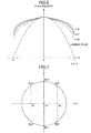
- FIG. 9A, 9B a flow passage of a circular pipe having a bent tube (elbow portion) and a baffle plate (partially sealing the flow passage cross-section downstream the bent tube) disposed therein.
- the baffle plate is disposed at a position X in FIG. 9A , and a cross-section thereof is semicircular as illustrated in FIG. 9B .
- the flow passage cross-section has a circular shape having a diameter of 83 mm.
- a test fluid (water) continues to flow with a constant flow rate of 5 (liter/sec.).
- a flow rate is measured at a cross-section A (immediately downstream the bent tube and baffle plate: a position about 200 mm away from the position X in an axial direction). Note that the estimated flow velocity distribution is derived by a preliminary simulation. A reverse flow occurs downstream the baffle plate, so that it is required to formulate Gaussian quadrature with virtually offsetting the zero-point of the flow velocity distribution.
- V z1 (x) a constant function (single the flow passage cross-section average of the estimated flow velocity)
- the weighting function was formulated based on the Formulas (16) to (18), and the flow rate was measured according to the method of the second embodiment.
- a flow rate was measured at the cross-section A according to the conventional art in the Patent Documents 3 and 4 (Gauss-Chebyshev type quadrature). Furthermore, as a reference value of the flow rate, a flow rate was also measured at the cross-section B (sufficiently downstream the bent tube and baffle plate: a position of 3000 mm or more away from the position X in an axial direction) using a general-purpose flow rate measurement apparatus.
- Each value of the node x i and a coefficient w i of Gaussian quadrature, V z0 (x i ), Q z0 , V z1 (x i ) and Q z1 when the flow rate is measured according to the method of the second embodiment of the present invention is as follows. Note that the radius of the flow passage is assumed to be 1, and the estimated flow velocity is normalized to be 1 in an average of flow passage cross-section.
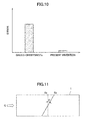
- FIG. 10 illustrates an absolute value of a difference between "a flow rate measured at a cross-section B" and "a flow rate measured at a cross-section A"' in each case of using a conventional Gauss-Chebyshev quadrature and of using the method of the second embodiment, as a flow rate measurement method at the cross-section A.
- the figure shows that the present invention is capable of reducing the flow rate measurement error to about the one-tenth thereof, as compared to the conventional art.
- the present invention makes it possible to measure the flow rate in the same principle.
- a flow passage cross-section S 2 inclined at an angle ⁇ (phi) with respect to an axis of the flow passage (which is obtained by rotating the flow passage cross-section S 1 by ⁇ (phi) about the x-axis in FIG. 1 ) is used as illustrated in FIG. 11
- the flow rate can be measured by defining the x- and y-coordinates on the flow passage cross-section S 2 as illustrated in FIG. 12 , and in the similar method as that already described above.
- the fluid is flowing in the axial direction of the flow passage pipe arrangement 1 as illustrated in FIG.
- each of the positions A*, B* for performing transmission and receipt of the ultrasonic wave may be the position shifted from each of A, B illustrated in FIG. 12 by a given distance in axially opposite directions of the flow passage pipe arrangement 1.
- the average flow velocity obtained by using the Formula (4) multiplied by cos ⁇ (phi) provides V z (x i ).
- v z (x, y) can be determined to perform the flow rate measurement in a similar manner by using a normal-directional component corresponding to each position (x, y) on the flow passage cross-section (using different ⁇ (phi) at each position (x, y)).
- the measurement method and measurement apparatus of the present invention can be potentially used for high-accuracy general flow rate measurement. For example, when used in an actual plant etc., it becomes possible to perform an accurate measurement under the flow velocity distribution of unstraightened flow in contrast to the conventional way. Thus, it can be expected, for example, to shorten the pipe line elongated for flow-straightening, improve the degree of freedom in a position for attaching a flowmeter, and so on.
Landscapes
- Physics & Mathematics (AREA)
- Fluid Mechanics (AREA)
- General Physics & Mathematics (AREA)
- Electromagnetism (AREA)
- Measuring Volume Flow (AREA)
Applications Claiming Priority (1)
| Application Number | Priority Date | Filing Date | Title |
|---|---|---|---|
| JP2013217695A JP6212762B2 (ja) | 2013-10-18 | 2013-10-18 | 流量計測方法及び装置 |
Publications (3)
| Publication Number | Publication Date |
|---|---|
| EP2863187A2 true EP2863187A2 (de) | 2015-04-22 |
| EP2863187A3 EP2863187A3 (de) | 2015-05-20 |
| EP2863187B1 EP2863187B1 (de) | 2016-10-05 |
Family
ID=51703109
Family Applications (1)
| Application Number | Title | Priority Date | Filing Date |
|---|---|---|---|
| EP14189280.2A Not-in-force EP2863187B1 (de) | 2013-10-18 | 2014-10-16 | Durchflussmessverfahren und Vorrichtung |
Country Status (3)
| Country | Link |
|---|---|
| US (1) | US10352741B2 (de) |
| EP (1) | EP2863187B1 (de) |
| JP (1) | JP6212762B2 (de) |
Cited By (2)
| Publication number | Priority date | Publication date | Assignee | Title |
|---|---|---|---|---|
| US20150112614A1 (en) * | 2013-10-18 | 2015-04-23 | Japan Aerospace Exploration Agency | Flow rate measurement method and apparatus |
| CN116593731A (zh) * | 2023-04-12 | 2023-08-15 | 中电华创电力技术研究有限公司 | 一种锅炉一次风速的测量装置及方法 |
Families Citing this family (6)
| Publication number | Priority date | Publication date | Assignee | Title |
|---|---|---|---|---|
| US9304024B2 (en) * | 2014-01-13 | 2016-04-05 | Cameron International Corporation | Acoustic flow measurement device including a plurality of chordal planes each having a plurality of axial velocity measurements using transducer pairs |
| US10393568B2 (en) * | 2015-12-28 | 2019-08-27 | Cameron International Corporation | Ultrasonic meter employing two or more dissimilar chordal multipath integration methods in one body |
| JP6374893B2 (ja) | 2016-02-02 | 2018-08-15 | 矢崎総業株式会社 | 車両用回路体 |
| CN107515030B (zh) * | 2017-08-30 | 2019-08-23 | 华南理工大学 | 一种多声道超声流量计的各声道流速加权系数确定方法 |
| EP3835731B1 (de) * | 2018-08-11 | 2024-08-21 | Li, Yanqin | Verfahren und system zur messung der axialströmungsratenverteilung und des durchflusses in einem rohr unter verwendung eines akustikwellenverfahrens |
| CN118761285B (zh) * | 2024-09-02 | 2025-03-21 | 长江三峡集团实业发展(北京)有限公司 | 一种水库渗流量的计算方法、装置、设备及介质 |
Citations (3)
| Publication number | Priority date | Publication date | Assignee | Title |
|---|---|---|---|---|
| US3564912A (en) | 1968-10-28 | 1971-02-23 | Westinghouse Electric Corp | Fluid flow measurement system |
| US3940985A (en) | 1975-04-18 | 1976-03-02 | Westinghouse Electric Corporation | Fluid flow measurement system for pipes |
| JP2001208584A (ja) | 2000-01-26 | 2001-08-03 | Natl Inst Of Advanced Industrial Science & Technology Meti | 流量測定装置 |
Family Cites Families (34)
| Publication number | Priority date | Publication date | Assignee | Title |
|---|---|---|---|---|
| US3283574A (en) * | 1958-01-14 | 1966-11-08 | Roth Lab For Physical Res | Ultrasonic flowmeter |
| US3188862A (en) * | 1958-01-14 | 1965-06-15 | Roth Lab For Physical Res | Flowmeters |
| GB1422531A (en) * | 1972-02-07 | 1976-01-28 | English Clays Lovering Pochin | Hoses including devices for inducing streamline flow in fluids |
| US4109523A (en) * | 1977-10-21 | 1978-08-29 | Westinghouse Electric Corp. | Method of determining acoustic flow meter correction factor |
| US4317178A (en) * | 1979-03-01 | 1982-02-23 | Fischer & Porter Company | Multiple velocity traverse flow rate measuring technique |
| US4300401A (en) * | 1979-10-09 | 1981-11-17 | Panametrics, Inc. | Method and apparatus for determining fluid flow |
| US4336719A (en) * | 1980-07-11 | 1982-06-29 | Panametrics, Inc. | Ultrasonic flowmeters using waveguide antennas |
| JPS5870132A (ja) * | 1981-10-21 | 1983-04-26 | Yokogawa Hokushin Electric Corp | 超音波流量計 |
| JPS59195126A (ja) * | 1983-04-21 | 1984-11-06 | Yokogawa Hokushin Electric Corp | 超音波流量計 |
| US4856321A (en) * | 1983-07-29 | 1989-08-15 | Panametrics, Inc. | Apparatus and methods for measuring fluid flow parameters |
| US4754650A (en) * | 1983-07-29 | 1988-07-05 | Panametrics, Inc. | Apparatus and methods for measuring fluid flow parameters |
| JPS6262218A (ja) * | 1985-09-12 | 1987-03-18 | Kansai Electric Power Co Inc:The | 超音波流量計 |
| JPH0749976B2 (ja) * | 1986-02-26 | 1995-05-31 | 富士電機株式会社 | 超音波式測定装置 |
| US5741980A (en) * | 1994-11-02 | 1998-04-21 | Foster-Miller, Inc. | Flow analysis system and method |
| US5597962A (en) * | 1995-03-31 | 1997-01-28 | Caldon, Inc. | Apparatus for determining fluid flow |
| EP1182431A4 (de) * | 1999-03-17 | 2006-06-14 | Matsushita Electric Industrial Co Ltd | Ultraschall-durchflussmeter |
| JP2001056244A (ja) * | 1999-08-19 | 2001-02-27 | Kaijo Corp | 超音波流量計 |
| US6502465B1 (en) * | 1999-09-27 | 2003-01-07 | Ohio University | Determining gas and liquid flow rates in a multi-phase flow |
| JP2001183200A (ja) * | 1999-12-28 | 2001-07-06 | Tokimec Inc | 流量計及び流量測定方法 |
| TW585995B (en) * | 2000-10-10 | 2004-05-01 | Matsushita Electric Industrial Co Ltd | Flow meter |
| US6732595B2 (en) * | 2002-07-18 | 2004-05-11 | Panametrics, Inc. | Method of and system for determining the mass flow rate of a fluid flowing in a conduit |
| US6837113B1 (en) * | 2003-09-05 | 2005-01-04 | Daniel Industries, Inc. | Enhanced velocity estimation in ultrasonic flow meters |
| DE10361464A1 (de) * | 2003-12-23 | 2005-07-28 | Endress + Hauser Flowtec Ag, Reinach | Vorrichtung zur Bestimmung und/oder Überwachung des Volumen- und/oder Massendurchflusses eines Messmediums |
| KR100562266B1 (ko) * | 2004-08-11 | 2006-03-22 | (주)씨엠엔텍 | 초음파다회선유량계의 이중적분식 유속측정방법 |
| JP2007152074A (ja) * | 2005-01-21 | 2007-06-21 | Chikayoshi Sumi | 変位又は歪計測方法及び装置、速度計測方法、弾性率・粘弾性率計測装置、及び、超音波診断装置 |
| US7523676B2 (en) * | 2006-12-07 | 2009-04-28 | General Electric Company | Ultrasonic flow rate measurement method and system |
| RU2347102C1 (ru) * | 2007-11-21 | 2009-02-20 | Общество с ограниченной ответственностью "Энергопромприбор" | Способ определения объемного расхода жидкости в трубопроводах гидроэлектростанций (варианты) |
| US7942068B2 (en) * | 2009-03-11 | 2011-05-17 | Ge Infrastructure Sensing, Inc. | Method and system for multi-path ultrasonic flow rate measurement |
| JP5550443B2 (ja) * | 2010-05-13 | 2014-07-16 | 日立アロカメディカル株式会社 | 超音波診断装置及び該装置における数値シミュレーション方法 |
| JP2012220465A (ja) * | 2011-04-14 | 2012-11-12 | Panasonic Corp | 流量計測装置 |
| DE102011075997A1 (de) * | 2011-05-17 | 2012-11-22 | Endress + Hauser Flowtec Ag | Ultraschall-Durchflussmessgerät |
| WO2013051272A1 (ja) * | 2011-10-06 | 2013-04-11 | パナソニック株式会社 | 流量計測装置の設定方法 |
| JP5919479B2 (ja) * | 2012-11-08 | 2016-05-18 | パナソニックIpマネジメント株式会社 | 超音波流量計 |
| JP6212762B2 (ja) * | 2013-10-18 | 2017-10-18 | 国立研究開発法人宇宙航空研究開発機構 | 流量計測方法及び装置 |
-
2013
- 2013-10-18 JP JP2013217695A patent/JP6212762B2/ja active Active
-
2014
- 2014-10-14 US US14/514,304 patent/US10352741B2/en active Active
- 2014-10-16 EP EP14189280.2A patent/EP2863187B1/de not_active Not-in-force
Patent Citations (4)
| Publication number | Priority date | Publication date | Assignee | Title |
|---|---|---|---|---|
| US3564912A (en) | 1968-10-28 | 1971-02-23 | Westinghouse Electric Corp | Fluid flow measurement system |
| US3940985A (en) | 1975-04-18 | 1976-03-02 | Westinghouse Electric Corporation | Fluid flow measurement system for pipes |
| JPS51129261A (en) | 1975-04-18 | 1976-11-10 | Westinghouse Electric Corp | Flow meter |
| JP2001208584A (ja) | 2000-01-26 | 2001-08-03 | Natl Inst Of Advanced Industrial Science & Technology Meti | 流量測定装置 |
Cited By (3)
| Publication number | Priority date | Publication date | Assignee | Title |
|---|---|---|---|---|
| US20150112614A1 (en) * | 2013-10-18 | 2015-04-23 | Japan Aerospace Exploration Agency | Flow rate measurement method and apparatus |
| US10352741B2 (en) * | 2013-10-18 | 2019-07-16 | Japan Aerospace Exploration Agency | Flow rate measurement method and apparatus |
| CN116593731A (zh) * | 2023-04-12 | 2023-08-15 | 中电华创电力技术研究有限公司 | 一种锅炉一次风速的测量装置及方法 |
Also Published As
| Publication number | Publication date |
|---|---|
| US10352741B2 (en) | 2019-07-16 |
| JP6212762B2 (ja) | 2017-10-18 |
| US20150112614A1 (en) | 2015-04-23 |
| EP2863187B1 (de) | 2016-10-05 |
| JP2015078962A (ja) | 2015-04-23 |
| EP2863187A3 (de) | 2015-05-20 |
Similar Documents
| Publication | Publication Date | Title |
|---|---|---|
| EP2863187A2 (de) | Durchflussmessverfahren und Vorrichtung | |
| EP2909587B1 (de) | Ultraschall-durchflussmesssystem mit einem vorgeschalteten druckwandler | |
| US7984637B2 (en) | System and method for field calibration of flow meters | |
| US4109523A (en) | Method of determining acoustic flow meter correction factor | |
| US9134156B2 (en) | Determination of reference values for ultrasonic flow metering systems | |
| US9134154B2 (en) | Percentage deviation based evaluation of velocity dependent characteristics in ultrasonic flow metering systems | |
| US10520480B2 (en) | Deconvolution method for emissions measurement | |
| EP3729017B1 (de) | Durchflussmesssystem und durchflussmessverfahren | |
| US12188807B2 (en) | Ultrasonic meter employing two or more dissimilar chordal multipath integration methods in one body | |
| US20170328803A1 (en) | Position estimation device, position estimation system, position estimation method, and computer-readable recording medium | |
| CN106895890A (zh) | 一种多声道超声波气体流量计声道权系数计算方法 | |
| CN103106332B (zh) | 一种测量不确定度的分析方法 | |
| Tereshchenko et al. | Acoustical multipath flow measurements based on quadrature integration methods | |
| US7958178B2 (en) | Finite impulse response filter for a time-synchronized system | |
| RU2541919C1 (ru) | Способ повышения точности аппроксимации при выделении полезного сигнала в условиях априорной неопределенности и устройство, его реализующее | |
| Brown et al. | Quantitative self-verification, a breakthrough in ultrasonic metering technology | |
| CN106771600A (zh) | 频率失配条件下的自适应无偏相位差估计方法 | |
| CN120907622A (zh) | 一种流体速度的确定方法、装置、超声流量计及存储介质 | |
| CN105890684A (zh) | 一种采用高斯-雅可比多项式确定声道位置的设置新方法 | |
| Harman | Turbulence Profile Effects on the Accuracy of Ultrasonic Meters | |
| bin Wan Hamzah | COMPARATIVE STUDV OF UNCERTAINTV ESTIMATION USING ANALYTICAL, AND NUMERICAL, MIETHOD |
Legal Events
| Date | Code | Title | Description |
|---|---|---|---|
| PUAL | Search report despatched |
Free format text: ORIGINAL CODE: 0009013 |
|
| PUAI | Public reference made under article 153(3) epc to a published international application that has entered the european phase |
Free format text: ORIGINAL CODE: 0009012 |
|
| 17P | Request for examination filed |
Effective date: 20141016 |
|
| AK | Designated contracting states |
Kind code of ref document: A2 Designated state(s): AL AT BE BG CH CY CZ DE DK EE ES FI FR GB GR HR HU IE IS IT LI LT LU LV MC MK MT NL NO PL PT RO RS SE SI SK SM TR |
|
| AX | Request for extension of the european patent |
Extension state: BA ME |
|
| AK | Designated contracting states |
Kind code of ref document: A3 Designated state(s): AL AT BE BG CH CY CZ DE DK EE ES FI FR GB GR HR HU IE IS IT LI LT LU LV MC MK MT NL NO PL PT RO RS SE SI SK SM TR |
|
| AX | Request for extension of the european patent |
Extension state: BA ME |
|
| RIC1 | Information provided on ipc code assigned before grant |
Ipc: G01F 1/66 20060101AFI20150413BHEP Ipc: G01P 5/24 20060101ALI20150413BHEP Ipc: G01P 5/00 20060101ALI20150413BHEP |
|
| R17P | Request for examination filed (corrected) |
Effective date: 20151119 |
|
| RBV | Designated contracting states (corrected) |
Designated state(s): AL AT BE BG CH CY CZ DE DK EE ES FI FR GB GR HR HU IE IS IT LI LT LU LV MC MK MT NL NO PL PT RO RS SE SI SK SM TR |
|
| REG | Reference to a national code |
Ref country code: DE Ref legal event code: R079 Ref document number: 602014004074 Country of ref document: DE Free format text: PREVIOUS MAIN CLASS: G01F0001660000 Ipc: G01F0001000000 |
|
| GRAP | Despatch of communication of intention to grant a patent |
Free format text: ORIGINAL CODE: EPIDOSNIGR1 |
|
| INTG | Intention to grant announced |
Effective date: 20160426 |
|
| RIC1 | Information provided on ipc code assigned before grant |
Ipc: G01F 1/00 20060101AFI20160418BHEP Ipc: G01F 1/66 20060101ALI20160418BHEP Ipc: G01F 1/05 20060101ALI20160418BHEP |
|
| GRAS | Grant fee paid |
Free format text: ORIGINAL CODE: EPIDOSNIGR3 |
|
| GRAJ | Information related to disapproval of communication of intention to grant by the applicant or resumption of examination proceedings by the epo deleted |
Free format text: ORIGINAL CODE: EPIDOSDIGR1 |
|
| GRAL | Information related to payment of fee for publishing/printing deleted |
Free format text: ORIGINAL CODE: EPIDOSDIGR3 |
|
| GRAR | Information related to intention to grant a patent recorded |
Free format text: ORIGINAL CODE: EPIDOSNIGR71 |
|
| GRAA | (expected) grant |
Free format text: ORIGINAL CODE: 0009210 |
|
| INTC | Intention to grant announced (deleted) | ||
| RIN1 | Information on inventor provided before grant (corrected) |
Inventor name: HORI, SHUSUKE Inventor name: UCHIUMI, MASAHARU Inventor name: YOSHIDA, YOSHIKI Inventor name: NANRI, HIDEAKI Inventor name: KANNAN, HIROKI |
|
| AK | Designated contracting states |
Kind code of ref document: B1 Designated state(s): AL AT BE BG CH CY CZ DE DK EE ES FI FR GB GR HR HU IE IS IT LI LT LU LV MC MK MT NL NO PL PT RO RS SE SI SK SM TR |
|
| INTG | Intention to grant announced |
Effective date: 20160830 |
|
| REG | Reference to a national code |
Ref country code: GB Ref legal event code: FG4D |
|
| REG | Reference to a national code |
Ref country code: CH Ref legal event code: EP Ref country code: FR Ref legal event code: PLFP Year of fee payment: 3 |
|
| REG | Reference to a national code |
Ref country code: AT Ref legal event code: REF Ref document number: 835040 Country of ref document: AT Kind code of ref document: T Effective date: 20161015 |
|
| REG | Reference to a national code |
Ref country code: IE Ref legal event code: FG4D |
|
| REG | Reference to a national code |
Ref country code: DE Ref legal event code: R096 Ref document number: 602014004074 Country of ref document: DE |
|
| REG | Reference to a national code |
Ref country code: NL Ref legal event code: MP Effective date: 20161005 |
|
| REG | Reference to a national code |
Ref country code: LT Ref legal event code: MG4D |
|
| PG25 | Lapsed in a contracting state [announced via postgrant information from national office to epo] |
Ref country code: BE Free format text: LAPSE BECAUSE OF NON-PAYMENT OF DUE FEES Effective date: 20161031 Ref country code: LV Free format text: LAPSE BECAUSE OF FAILURE TO SUBMIT A TRANSLATION OF THE DESCRIPTION OR TO PAY THE FEE WITHIN THE PRESCRIBED TIME-LIMIT Effective date: 20161005 |
|
| REG | Reference to a national code |
Ref country code: AT Ref legal event code: MK05 Ref document number: 835040 Country of ref document: AT Kind code of ref document: T Effective date: 20161005 |
|
| PG25 | Lapsed in a contracting state [announced via postgrant information from national office to epo] |
Ref country code: NO Free format text: LAPSE BECAUSE OF FAILURE TO SUBMIT A TRANSLATION OF THE DESCRIPTION OR TO PAY THE FEE WITHIN THE PRESCRIBED TIME-LIMIT Effective date: 20170105 Ref country code: LT Free format text: LAPSE BECAUSE OF FAILURE TO SUBMIT A TRANSLATION OF THE DESCRIPTION OR TO PAY THE FEE WITHIN THE PRESCRIBED TIME-LIMIT Effective date: 20161005 Ref country code: SE Free format text: LAPSE BECAUSE OF FAILURE TO SUBMIT A TRANSLATION OF THE DESCRIPTION OR TO PAY THE FEE WITHIN THE PRESCRIBED TIME-LIMIT Effective date: 20161005 Ref country code: GR Free format text: LAPSE BECAUSE OF FAILURE TO SUBMIT A TRANSLATION OF THE DESCRIPTION OR TO PAY THE FEE WITHIN THE PRESCRIBED TIME-LIMIT Effective date: 20170106 |
|
| PG25 | Lapsed in a contracting state [announced via postgrant information from national office to epo] |
Ref country code: NL Free format text: LAPSE BECAUSE OF FAILURE TO SUBMIT A TRANSLATION OF THE DESCRIPTION OR TO PAY THE FEE WITHIN THE PRESCRIBED TIME-LIMIT Effective date: 20161005 Ref country code: RS Free format text: LAPSE BECAUSE OF FAILURE TO SUBMIT A TRANSLATION OF THE DESCRIPTION OR TO PAY THE FEE WITHIN THE PRESCRIBED TIME-LIMIT Effective date: 20161005 Ref country code: HR Free format text: LAPSE BECAUSE OF FAILURE TO SUBMIT A TRANSLATION OF THE DESCRIPTION OR TO PAY THE FEE WITHIN THE PRESCRIBED TIME-LIMIT Effective date: 20161005 Ref country code: AT Free format text: LAPSE BECAUSE OF FAILURE TO SUBMIT A TRANSLATION OF THE DESCRIPTION OR TO PAY THE FEE WITHIN THE PRESCRIBED TIME-LIMIT Effective date: 20161005 Ref country code: ES Free format text: LAPSE BECAUSE OF FAILURE TO SUBMIT A TRANSLATION OF THE DESCRIPTION OR TO PAY THE FEE WITHIN THE PRESCRIBED TIME-LIMIT Effective date: 20161005 Ref country code: PL Free format text: LAPSE BECAUSE OF FAILURE TO SUBMIT A TRANSLATION OF THE DESCRIPTION OR TO PAY THE FEE WITHIN THE PRESCRIBED TIME-LIMIT Effective date: 20161005 Ref country code: BE Free format text: LAPSE BECAUSE OF FAILURE TO SUBMIT A TRANSLATION OF THE DESCRIPTION OR TO PAY THE FEE WITHIN THE PRESCRIBED TIME-LIMIT Effective date: 20161005 Ref country code: PT Free format text: LAPSE BECAUSE OF FAILURE TO SUBMIT A TRANSLATION OF THE DESCRIPTION OR TO PAY THE FEE WITHIN THE PRESCRIBED TIME-LIMIT Effective date: 20170206 Ref country code: IS Free format text: LAPSE BECAUSE OF FAILURE TO SUBMIT A TRANSLATION OF THE DESCRIPTION OR TO PAY THE FEE WITHIN THE PRESCRIBED TIME-LIMIT Effective date: 20170205 Ref country code: FI Free format text: LAPSE BECAUSE OF FAILURE TO SUBMIT A TRANSLATION OF THE DESCRIPTION OR TO PAY THE FEE WITHIN THE PRESCRIBED TIME-LIMIT Effective date: 20161005 |
|
| REG | Reference to a national code |
Ref country code: DE Ref legal event code: R097 Ref document number: 602014004074 Country of ref document: DE |
|
| REG | Reference to a national code |
Ref country code: IE Ref legal event code: MM4A |
|
| PG25 | Lapsed in a contracting state [announced via postgrant information from national office to epo] |
Ref country code: MC Free format text: LAPSE BECAUSE OF FAILURE TO SUBMIT A TRANSLATION OF THE DESCRIPTION OR TO PAY THE FEE WITHIN THE PRESCRIBED TIME-LIMIT Effective date: 20161005 Ref country code: RO Free format text: LAPSE BECAUSE OF FAILURE TO SUBMIT A TRANSLATION OF THE DESCRIPTION OR TO PAY THE FEE WITHIN THE PRESCRIBED TIME-LIMIT Effective date: 20161005 Ref country code: CZ Free format text: LAPSE BECAUSE OF FAILURE TO SUBMIT A TRANSLATION OF THE DESCRIPTION OR TO PAY THE FEE WITHIN THE PRESCRIBED TIME-LIMIT Effective date: 20161005 Ref country code: DK Free format text: LAPSE BECAUSE OF FAILURE TO SUBMIT A TRANSLATION OF THE DESCRIPTION OR TO PAY THE FEE WITHIN THE PRESCRIBED TIME-LIMIT Effective date: 20161005 Ref country code: SK Free format text: LAPSE BECAUSE OF FAILURE TO SUBMIT A TRANSLATION OF THE DESCRIPTION OR TO PAY THE FEE WITHIN THE PRESCRIBED TIME-LIMIT Effective date: 20161005 Ref country code: EE Free format text: LAPSE BECAUSE OF FAILURE TO SUBMIT A TRANSLATION OF THE DESCRIPTION OR TO PAY THE FEE WITHIN THE PRESCRIBED TIME-LIMIT Effective date: 20161005 |
|
| PLBE | No opposition filed within time limit |
Free format text: ORIGINAL CODE: 0009261 |
|
| STAA | Information on the status of an ep patent application or granted ep patent |
Free format text: STATUS: NO OPPOSITION FILED WITHIN TIME LIMIT |
|
| PG25 | Lapsed in a contracting state [announced via postgrant information from national office to epo] |
Ref country code: SM Free format text: LAPSE BECAUSE OF FAILURE TO SUBMIT A TRANSLATION OF THE DESCRIPTION OR TO PAY THE FEE WITHIN THE PRESCRIBED TIME-LIMIT Effective date: 20161005 Ref country code: IT Free format text: LAPSE BECAUSE OF FAILURE TO SUBMIT A TRANSLATION OF THE DESCRIPTION OR TO PAY THE FEE WITHIN THE PRESCRIBED TIME-LIMIT Effective date: 20161005 Ref country code: BG Free format text: LAPSE BECAUSE OF FAILURE TO SUBMIT A TRANSLATION OF THE DESCRIPTION OR TO PAY THE FEE WITHIN THE PRESCRIBED TIME-LIMIT Effective date: 20170105 Ref country code: LU Free format text: LAPSE BECAUSE OF NON-PAYMENT OF DUE FEES Effective date: 20161016 |
|
| 26N | No opposition filed |
Effective date: 20170706 |
|
| REG | Reference to a national code |
Ref country code: FR Ref legal event code: PLFP Year of fee payment: 4 |
|
| PG25 | Lapsed in a contracting state [announced via postgrant information from national office to epo] |
Ref country code: SI Free format text: LAPSE BECAUSE OF FAILURE TO SUBMIT A TRANSLATION OF THE DESCRIPTION OR TO PAY THE FEE WITHIN THE PRESCRIBED TIME-LIMIT Effective date: 20161005 Ref country code: IE Free format text: LAPSE BECAUSE OF NON-PAYMENT OF DUE FEES Effective date: 20161016 |
|
| PG25 | Lapsed in a contracting state [announced via postgrant information from national office to epo] |
Ref country code: HU Free format text: LAPSE BECAUSE OF FAILURE TO SUBMIT A TRANSLATION OF THE DESCRIPTION OR TO PAY THE FEE WITHIN THE PRESCRIBED TIME-LIMIT; INVALID AB INITIO Effective date: 20141016 |
|
| REG | Reference to a national code |
Ref country code: CH Ref legal event code: PL |
|
| PG25 | Lapsed in a contracting state [announced via postgrant information from national office to epo] |
Ref country code: MT Free format text: LAPSE BECAUSE OF NON-PAYMENT OF DUE FEES Effective date: 20161031 Ref country code: CY Free format text: LAPSE BECAUSE OF FAILURE TO SUBMIT A TRANSLATION OF THE DESCRIPTION OR TO PAY THE FEE WITHIN THE PRESCRIBED TIME-LIMIT Effective date: 20161005 Ref country code: MK Free format text: LAPSE BECAUSE OF FAILURE TO SUBMIT A TRANSLATION OF THE DESCRIPTION OR TO PAY THE FEE WITHIN THE PRESCRIBED TIME-LIMIT Effective date: 20161005 |
|
| PG25 | Lapsed in a contracting state [announced via postgrant information from national office to epo] |
Ref country code: LI Free format text: LAPSE BECAUSE OF NON-PAYMENT OF DUE FEES Effective date: 20171031 Ref country code: CH Free format text: LAPSE BECAUSE OF NON-PAYMENT OF DUE FEES Effective date: 20171031 |
|
| REG | Reference to a national code |
Ref country code: FR Ref legal event code: PLFP Year of fee payment: 5 |
|
| PG25 | Lapsed in a contracting state [announced via postgrant information from national office to epo] |
Ref country code: TR Free format text: LAPSE BECAUSE OF FAILURE TO SUBMIT A TRANSLATION OF THE DESCRIPTION OR TO PAY THE FEE WITHIN THE PRESCRIBED TIME-LIMIT Effective date: 20161005 |
|
| PG25 | Lapsed in a contracting state [announced via postgrant information from national office to epo] |
Ref country code: AL Free format text: LAPSE BECAUSE OF FAILURE TO SUBMIT A TRANSLATION OF THE DESCRIPTION OR TO PAY THE FEE WITHIN THE PRESCRIBED TIME-LIMIT Effective date: 20161005 |
|
| PGFP | Annual fee paid to national office [announced via postgrant information from national office to epo] |
Ref country code: DE Payment date: 20211020 Year of fee payment: 8 Ref country code: GB Payment date: 20211022 Year of fee payment: 8 |
|
| PGFP | Annual fee paid to national office [announced via postgrant information from national office to epo] |
Ref country code: FR Payment date: 20211022 Year of fee payment: 8 |
|
| REG | Reference to a national code |
Ref country code: DE Ref legal event code: R119 Ref document number: 602014004074 Country of ref document: DE |
|
| GBPC | Gb: european patent ceased through non-payment of renewal fee |
Effective date: 20221016 |
|
| PG25 | Lapsed in a contracting state [announced via postgrant information from national office to epo] |
Ref country code: FR Free format text: LAPSE BECAUSE OF NON-PAYMENT OF DUE FEES Effective date: 20221031 Ref country code: DE Free format text: LAPSE BECAUSE OF NON-PAYMENT OF DUE FEES Effective date: 20230503 |
|
| PG25 | Lapsed in a contracting state [announced via postgrant information from national office to epo] |
Ref country code: GB Free format text: LAPSE BECAUSE OF NON-PAYMENT OF DUE FEES Effective date: 20221016 |