EP3729017B1 - Durchflussmesssystem und durchflussmessverfahren - Google Patents
Durchflussmesssystem und durchflussmessverfahren Download PDFInfo
- Publication number
- EP3729017B1 EP3729017B1 EP18833787.7A EP18833787A EP3729017B1 EP 3729017 B1 EP3729017 B1 EP 3729017B1 EP 18833787 A EP18833787 A EP 18833787A EP 3729017 B1 EP3729017 B1 EP 3729017B1
- Authority
- EP
- European Patent Office
- Prior art keywords
- fluid
- flow
- factor
- flow meter
- meter
- Prior art date
- Legal status (The legal status is an assumption and is not a legal conclusion. Google has not performed a legal analysis and makes no representation as to the accuracy of the status listed.)
- Active
Links
Images


Classifications
-
- G—PHYSICS
- G01—MEASURING; TESTING
- G01F—MEASURING VOLUME, VOLUME FLOW, MASS FLOW OR LIQUID LEVEL; METERING BY VOLUME
- G01F1/00—Measuring the volume flow or mass flow of fluid or fluent solid material wherein the fluid passes through a meter in a continuous flow
- G01F1/66—Measuring the volume flow or mass flow of fluid or fluent solid material wherein the fluid passes through a meter in a continuous flow by measuring frequency, phase shift or propagation time of electromagnetic or other waves, e.g. using ultrasonic flowmeters
- G01F1/667—Arrangements of transducers for ultrasonic flowmeters; Circuits for operating ultrasonic flowmeters
-
- G—PHYSICS
- G01—MEASURING; TESTING
- G01F—MEASURING VOLUME, VOLUME FLOW, MASS FLOW OR LIQUID LEVEL; METERING BY VOLUME
- G01F1/00—Measuring the volume flow or mass flow of fluid or fluent solid material wherein the fluid passes through a meter in a continuous flow
- G01F1/66—Measuring the volume flow or mass flow of fluid or fluent solid material wherein the fluid passes through a meter in a continuous flow by measuring frequency, phase shift or propagation time of electromagnetic or other waves, e.g. using ultrasonic flowmeters
- G01F1/662—Constructional details
-
- G—PHYSICS
- G01—MEASURING; TESTING
- G01F—MEASURING VOLUME, VOLUME FLOW, MASS FLOW OR LIQUID LEVEL; METERING BY VOLUME
- G01F25/00—Testing or calibration of apparatus for measuring volume, volume flow or liquid level or for metering by volume
- G01F25/10—Testing or calibration of apparatus for measuring volume, volume flow or liquid level or for metering by volume of flowmeters
-
- G—PHYSICS
- G01—MEASURING; TESTING
- G01F—MEASURING VOLUME, VOLUME FLOW, MASS FLOW OR LIQUID LEVEL; METERING BY VOLUME
- G01F15/00—Details of, or accessories for, apparatus of groups G01F1/00 - G01F13/00 insofar as such details or appliances are not adapted to particular types of such apparatus
-
- G—PHYSICS
- G01—MEASURING; TESTING
- G01F—MEASURING VOLUME, VOLUME FLOW, MASS FLOW OR LIQUID LEVEL; METERING BY VOLUME
- G01F25/00—Testing or calibration of apparatus for measuring volume, volume flow or liquid level or for metering by volume
- G01F25/10—Testing or calibration of apparatus for measuring volume, volume flow or liquid level or for metering by volume of flowmeters
- G01F25/11—Testing or calibration of apparatus for measuring volume, volume flow or liquid level or for metering by volume of flowmeters using a seal ball or piston in a test loop
-
- G—PHYSICS
- G01—MEASURING; TESTING
- G01F—MEASURING VOLUME, VOLUME FLOW, MASS FLOW OR LIQUID LEVEL; METERING BY VOLUME
- G01F25/00—Testing or calibration of apparatus for measuring volume, volume flow or liquid level or for metering by volume
- G01F25/10—Testing or calibration of apparatus for measuring volume, volume flow or liquid level or for metering by volume of flowmeters
- G01F25/13—Testing or calibration of apparatus for measuring volume, volume flow or liquid level or for metering by volume of flowmeters using a reference counter
Definitions
- the entities may use flow meters such as liquid ultrasonic flow meters.
- Ultrasonic flow meters transfer acoustic signals across fluids for flow measurements. Based on the acoustic signals, the ultrasonic flow meters determine average velocities of the fluids. An operator or other entity may calculate cross-sectional areas of the ultrasonic flow meters using known dimensions. Based on the average velocities and the cross-sectional areas, the ultrasonic flow meters determine volumes of the fluids flowing through the pipelines. An example of a prior art flow meter system is shown in US2014/0238148 .
- the flow meter system comprises a flow meter configured to enable a first flow of a first fluid through the flow meter, and transmitter electronics coupled to the flow meter and configured to calculate a first profile factor of the first fluid during the first flow, calculate a first meter factor corresponding to the first profile factor based on a single correlation between a plurality of profile factors and a plurality of meter factors for multiple fluids of different viscosities, and calculate a first volume of the first fluid using the first meter factor.
- the method comprises enabling a first flow of a first fluid through a flow meter, calculating a first profile factor (PF) of the first fluid during the first flow, calculating a first meter factor (MF) corresponding to the first profile factor based on a single correlation between a plurality of profile factors and a plurality of meter factors for multiple fluids of different viscosities, and calculating a first volume of the first fluid using the first meter factor.
- PF profile factor
- MF first meter factor
- the embodiments provide a correlation between PFs and MFs so that a flow meter system may calculate a different MF for each PF.
- the flow meter system makes more accurate measurements such as volume measurements within an error of about 0.15% or less.
- the flow meter system makes measurements for multiple fluids. This is because fluids of different viscosities or Reynolds numbers may not have overlapping PF ranges.
- PF ranges of multiple fluids may be combined into a single correlation between PFs and MFs.
- Other approaches based on velocity or flow rate may not make measurements for multiple fluids using a single correction curve because different hydrocarbon fluids have different curves that cannot be combined.
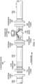
- FIG. 1 is a schematic diagram of a flow meter system 100.
- the flow meter system 100 comprises pipes 105, 125, 160; upstream flanges 110, 130, 150; downstream flanges 115, 135, 155; a flow conditioner 120; transmitter electronics 140; and a flow meter 145.
- a similar system is described in United States patent number 9,068,870 titled “Ultrasonic Flow Metering With Laminar to Turbulent Transition Flow Control" and filed by Daniel Measurement and Control, Inc. ("'870 Patent”).
- a downstream direction is a direction from left to right in which fluids flow through the flow meter system 100, and an upstream direction is a direction from right to left and opposite the downstream direction.
- the terms “downstream” and “upstream” are relative terms so that the downstream flange 115 is downstream from the upstream flange 110, but upstream from the upstream flange 130.
- the pipes 105, 125, 160 comprise materials such as high-carbon steel or stainless steel and allow fluids to freely flow.
- the fluids may be hydrocarbon liquids such as crude oil or refined liquids.
- the pipe 105 may have a length of at least two times its diameter, the pipe 125 may have a length of eight times its diameter, and the pipe 160 may have a length at least five times its diameter.
- the upstream flanges 110, 130, 150 and the downstream flanges 115, 135, 155 comprise materials such as high-carbon steel or stainless steel.
- the upstream flange 110 and the downstream flange 115 facilitate coupling of the pipe 105 to the pipe 125
- the upstream flange 130 and the downstream flange 135 facilitate coupling of the pipe 125 to the flow meter 145
- the upstream flange 150 and the downstream flange 155 facilitate coupling of the flow meter 145 to the pipe 160.
- the flow conditioner 120 conditions fluids flowing through it by eliminating swirls, reducing large-scale turbulence fluctuations, and improving mean velocity profiles of those fluids.
- the flow conditioner 120 does so in order to provide more accurate measurements at the flow meter 145.
- the flow conditioner 120 may be a tube bundle that directs the fluids through a series of tubes or may be a perforated plate that directs the fluids through small apertures.
- the flow meter system 100 does not comprise an expander, a reducer, or a pipe section connecting an expander or a reducer. Those components condition average velocity profiles of fluids and improve repeatability to enable measurements at Reynolds numbers below 5,000. However, such flow velocity reduction may not be necessary in the flow meter system 100 because the flow meter system 100 is designed to perform measurements at Reynolds numbers between 7,000 and 200,000.
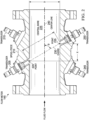
- FIG. 2 is a cross-sectional overhead view of the flow meter 145 in FIG. 1 .
- FIG. 2 shows that the flow meter 145 comprises a spool piece 210 and transducers 205, 215, 245, 250.
- the spool piece 210 defines a central bore 225 with a diameter D.
- the central bore 225 allows fluids to freely flow through it.
- the transducers 205, 215, 245, 250 are acoustic transceivers that generate and transmit acoustic signals on one hand and receive acoustic signals on the other hand.
- the acoustic signals may be ultrasonic signals above about 20 kHz.
- the transmitter electronics 140 shown in FIG. 1 transmit analog electrical signals to the transducers 205, 215, 245, 250.
- Piezoelectric elements in the transducers 205, 215, 245, 250 receive the analog electrical signals and vibrate in response, and the vibrations generate ultrasonic signals.
- the transducers 205, 215 transmit the ultrasonic signals through fluids flowing through the central bore 225 and to opposing transducers 245, 250.
- transducers 205, 215, 245, 250 For the transducers 205, 215, 245, 250 to receive acoustic signals, piezoelectric elements in the transducers 205, 215, 245, 250 receive the acoustic signals and vibrate in response, and the vibrations generate analog electrical signals.
- the transducers 205, 215, 245, 250 transmit the analog electrical signals to the transmitter electronics 140.
- the transmitter electronics 140 detect the analog electrical signals, digitize the analog electrical signals to create digital electrical signals, and analyze the digital electrical signals.
- a chord 230 exists between the transducer 205 and the transducer 250 at an angle ⁇ with respect to a centerline 240 of the flow meter 145.
- the chord 230 is a path for ultrasonic signals to travel from a point 220 in the transducer 205 to a point 235 in the transducer 250, or for ultrasonic signals to travel from the point 235 in the transducer 250 to the point 220 in the transducer 205.
- L is a length defining a linear distance of the chord 230 between the point 220 and the point 235
- X is a length defining an axial distance between the point 220 and the point 235
- T up is a time it takes for an acoustic signal to travel from the point 235 to the point 220 or a time of flight in an upstream direction
- T down is a time it takes for an acoustic signal to travel from the point 220 to the point 235 or a time of flight in a downstream direction.
- ⁇ is in units of m/s
- L is in units of m
- X is in units of m
- T up is in units of s
- T down is in units of s.
- T down is typically smaller than T up because T down is the time of flight for ultrasonic signals traveling in approximately a same direction as fluid direction while T up is the time of flight for ultrasonic signals traveling in approximately an opposite direction as the fluid direction.
- T up is the time of flight for ultrasonic signals traveling in approximately an opposite direction as the fluid direction.
- chord 230 is described, another chord exists between the transducer 215 and the transducer 245 at the angle ⁇ with respect to the centerline 240.
- a typical four-path ultrasonic flow meter has four chords.
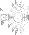
- FIG. 3 is a cross-sectional side elevation view of a portion 300 of the flow meter 145 in FIG. 1 .
- the portion 300 comprises the transmitter electronics 140 and the spool piece 210.
- the cross-sectional side elevation view in FIG. 3 shows that the flow meter 145 comprises the transducers 245, 250, 215, 205.
- the cross-sectional side elevation view in FIG. 3 also shows that the flow meter 145 comprises transducers 310, 320, 330, 340 and thus four chords.
- Chord A exists between the transducer 310 and the transducer 330
- chord B exists between the transducer 245 and the transducer 215
- chord C exists between the transducer 250 and the transducer 205
- chord D exists between the transducer 320 and the transducer 340.
- Chord C may be the same as the chord 230 in FIG. 2 .
- the transmitter electronics 140 calculate ⁇ A for chord A, ⁇ B for chord B, ⁇ C for chord C, and ⁇ D for chord D.
- PF is a dimensionless parameter.
- PF is a ratio of inner chordal flow velocities to outer chordal flow velocities, where chord B and chord C are inner chords and chord A and chord D are outer chords, and thus ⁇ B and ⁇ C are inner chordal flow velocities and ⁇ A and ⁇ D are outer chordal flow velocities.
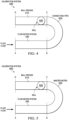
- FIG. 4 is a schematic diagram of a calibration system 400.
- the calibration system 400 performs direct proving and may be referred to as a ball prover flow meter calibration system.
- the calibration system 400 comprises the flow meter system 100 in FIG. 1 , a connecting pipe 430, and a ball prover 410.
- the ball prover 410 is a piece of standard equipment that provides precision measurements when calibrated.
- the ball prover 410 is either straight or curved and comprises a ball 420.
- the connecting pipe 430 connects the flow meter system 100 to the ball prover 410 so that the flow meter system 100 and the ball prover 410 are in series with each other.
- fluids enter the flow meter system 100 at point A, exit the flow meter system 100 at point B, move from point B to point C within the connecting pipe 430, enter the ball prover 410 at point C, push the ball 420 from point C to point D within the ball prover 410, and exit the ball prover 410 at point D.
- This system is called direct proving.
- FIG. 5 is a schematic diagram of another calibration system 500.
- the calibration system 500 is similar to the calibration system 400 in FIG. 4 .
- the calibration system 500 comprises the flow meter system 100 in FIG. 1 and a ball prover 510, and the ball prover 510 comprises a ball 520.
- the calibration system 500 instead of the connecting pipe 430 like in the calibration system 400, the calibration system 500 comprises a master meter 530. An operator or other entity pre-calibrates the master meter 530 against the ball prover 510.
- FIG. 6 is a flowchart illustrating a method 600 of multi-fluid calibration according to an embodiment of the disclosure.
- MFs are calculated.
- An operator uses either the calibration system 400 or the calibration system 500 to calculate the MFs.
- the operator calculates a volume Q ref of the ball prover 410 or 510 as follows:
- Q ref CS ref ⁇ L C ⁇ D .
- CS ref is a known cross-sectional area of the ball prover 410 or 510
- L C-D is a length of the ball prover 410 or 510 from point C to point D.
- Q ref is in units of m 3
- CS ref is in units of m 2
- L C-D is in units of m.
- the operator obtains and determines a volume of a fluid.
- the operator causes the volume of the fluid to flow through the flow meter system 100 from point A to B.
- w i is a chordal weighting factor for each chordal flow velocity ⁇ i .
- ⁇ avg is in units of m/s
- ⁇ i is in units of m/s
- w i is a dimensionless parameter.
- the operator then causes the volume of the fluid to pass the ball 420 or 520 from point C to point D in the ball prover 410 or 510, and the operator determines a time t it takes to do so.
- ⁇ avg is the average velocity of the fluid
- CS FMS is a known cross-sectional area of the flow meter system 100
- t is the time it takes the volume of the fluid to pass the ball 420 or 520 from point C to point D in the ball prover 410 or 510.
- MF Q ref Q FMS .
- MF may be a constant around 1, for instance 0.98.
- a ratio of a volume of the ball prover 410 or 510 to a volume of the flow meter system 100 yields MF.
- PFs are calculated.
- the transmitter electronics 140 calculate a PF while the fluid passes from point A to point B in the flow meter system 100.
- PF in equation (2) may be a constant between about 1.1 and 1.30.
- Steps 610 and 620 are repeated in order to obtain a plurality of MFs and plurality of corresponding PFs for the fluid.
- Steps 610 and 620 may be repeated to obtain a plurality of MFs and a plurality of corresponding PFs for additional fluids as well.
- a correlation between the MFs and the PFs is established.
- the operator provides the MFs and the PFs to an algorithm.
- the operator may do so for multiple fluids.
- the algorithm generates an MF-PF curve based on the MFs and PFs.
- Such an algorithm is known in the art and may be a software program run on a separate computing device.
- the algorithm determines a 0 - a 8 .
- the operator provides the MFs and the PFs to the algorithm separately for each fluid, and the algorithm generates MF-PF curves for each fluid.
- FIG. 7 is a graph 700 of MF-PF curves according to an embodiment of the disclosure.
- the x-axis represents a dimensionless PF
- the y-axis represents a dimensionless MF.
- a first curve 710 which is represented by downward-facing triangles and which corresponds to a low-viscosity fluid at about 11 cSt, provides a first correlation between PFs and MFs.
- a second curve 720 which is represented by diamonds and which corresponds to a high-viscosity fluid at about 90 cSt, provides a second correlation between PFs and MFs.
- the algorithm generates the first curve 710 and the second curve 720 using equation (7).
- the low-viscosity fluid has a PF range of about 1.17 to about 1.24
- the high-viscosity fluid has a PF range of about 1.24 to about 1.28
- the low-viscosity fluid and the high-viscosity fluid overlap at a PF of about 1.24 in the graph 700, so the correlation represents both low-viscosity fluids and high-viscosity fluids across a broad range of PFs from about 1.17 to about 1.28.
- the algorithm may do so by separately generating the first curve 710 and the second curve 720, or the algorithm may do so by generating a single curve that incorporates both the first curve 710 and the second curve 720.
- FIG. 8 is a graph 800 demonstrating a correlation between PF and Reynolds number.
- the x-axis represents a dimensionless Reynolds number
- the y-axis represents a dimensionless PF.
- a Reynolds number is a dimensionless parameter that describes whether a fluid is in laminar flow or turbulent flow.
- fluid flows with Reynolds numbers at or below 2,300 are laminar flows
- fluid flows with Reynolds numbers between 2,300 and 5,000 are transitional fluid flows in which the state of the fluid flow may rapidly change between laminar flow and turbulent flow
- fluid flows with Reynolds numbers at or above 5,000 are typically turbulent flows.
- a first curve 810 which is represented by downward-facing triangles and which corresponds to a low-viscosity fluid at about 11 cSt, provides a first correlation between Reynolds number and PF.
- a second curve 820 which is represented by diamonds and which corresponds to a high-viscosity fluid at about 90 cSt, provides a second correlation between Reynolds number and PF. As shown, a single value for Reynolds number does not correlate to more than one value for PF. Thus, the correlation also represents both low-viscosity fluids and high-viscosity fluids across a broad range of Reynolds numbers.
- the graph 800 shows that the range of Reynolds number extends from about 7,000 to about 185,000, but the correlation may represent fluids with a range of Reynolds number from about 7,000 to about 200,000 or any range therein.
- the correlation is stored in the transmitter electronics 140.
- the operator obtains the first curve 710 and the second curve 720 from the algorithm, combines the first curve 710 and the second curve 720 to form the correlation, and stores the correlation in the transmitter electronics 140.
- the transmitter electronics 140 may store the correlation as user input values in firmware.
- the correlation provides a correction to measurements such as volume measurements that the transmitter electronics 140 make.
- the flow meter system 100 may be referred to as a corrected or calibrated flow meter system or a MF-corrected or MF-calibrated flow meter system.
- Step 650 the flow meter system 100 is tested using the correlation.
- Step 650 may be referred to as verification.
- the corrected volume Q FMS ' corrects the volume Q FMS by multiplying the average velocity of the fluid ⁇ avg by MF .
- ⁇ avg is an average velocity of the fluid
- MF is an MF corresponding to a PF based on the correlation
- CS FMS is the known cross-sectional area of the flow meter system 100
- t is the time it takes for the volume of the fluid to pass the ball 420 from point C to point D in the ball prover 410.
- Q FMS ' is in units of m 3
- ⁇ avg is in units of m/s
- MF is dimensionless
- CS FMS is in units of m 2
- t is in units of s.
- the error margin is 0.15% or another error margin suitable for industry standards or other criteria.
- measurements are performed using the correlation.
- ⁇ avg is an average velocity of the fluid
- MF is an MF corresponding to a PF based on the correlation
- CS FMS is the known cross-sectional area of the flow meter system 100.
- t is the time it takes for the volume of the fluid to pass from point A to point B in the flow meter system 100.
- Point A and point B can be as far away from each other as possible.
- Q is in units of m 3
- v avg is in units of m/s
- MF is dimensionless
- CS FMS is in units of m 2
- t is in units of s.
- the transmitter electronics 140 calibrate the flow meter system 100 by correcting a calculation or measurement of Q. The transmitter electronics 140 may do so for multiple fluids.
- FIG. 9 is a flowchart illustrating a method 900 of fluid flow measurement according to an embodiment of the disclosure.
- the flow meter system 100 implements the method 900.
- a first flow of a first fluid is enabled.
- the flow meter system 100 enables a first fluid to flow through the flow meter 145.
- a first PF of the first fluid is calculated.
- the transmitter electronics 140 calculate the first PF using equation (2).
- a first MF corresponding to the first PF is calculated based on a correlation between PFs and MFs.
- the transmitter electronics 140 calculate the first MF based on the correlation described above with respect to step 630 in FIG. 6 .
- a first volume of the first fluid is calculated using the first MF.
- the transmitter electronics 140 calculate the first volume using MF as shown in equation (8).
- FIG. 10 is a model 1000 of multi-fluid calibration according to an embodiment of the disclosure.
- the transmitter electronics 140 implement the model 1000.
- a PF and velocity computer 1010 calculates PF using equation (2) and calculates ⁇ avg using equation (4).
- an MF-PF correlator 1020 provides MF using the correlation described in step 630 in FIG. 6 above.
- a volume/flow rate calculator 1030 uses ⁇ avg from the PF and velocity computer 1010 to calculates Q FMS using equation (5).
- a corrector 1040 calculates Q using equation (8).
- FIG. 11 is a schematic diagram of an apparatus 1100 according to an embodiment of the disclosure.
- the apparatus 1100 implements the disclosed embodiments.
- the apparatus 1100 may represent the transmitter electronics 140, implement a portion of the transmitter electronics 140, or implement a separate apparatus.
- the apparatus 1100 comprises ingress ports 1110 and an RX 1120 to receive data; a processor, logic unit, baseband unit, or CPU 1130 to process the data; a TX 1140 and egress ports 1150 to transmit the data; and a memory 1160 to store the data.
- the apparatus 1100 may also comprise OE components, EO components, or RF components coupled to the ingress ports 1110, the RX 1120, the TX 1140, and the egress ports 1150 for ingress or egress of electrical, optical, or RF signals.
- the processor 1130 is any suitable combination of hardware, middleware, firmware, or software.
- the processor 1130 comprises any combination of one or more CPU chips, cores, FPGAs, ASICs, or DSPs.
- the processor 1130 communicates with the ingress ports 1110, RX 1120, TX 1140, egress ports 1150, and memory 1160.
- the processor 1130 comprises a fluid measurer 1170, which implements the disclosed embodiments. The inclusion of the fluid measurer 1170 therefore provides a substantial improvement to the functionality of the apparatus 1100 and effects a transformation of the apparatus 1100 to a different state.
- the memory 1160 stores the fluid measurer 1170 as instructions, and the processor 1130 executes those instructions.
- any suitable combination of components implements the disclosed embodiments.
- the memory 1160 comprises one or more disks, tape drives, or solid-state drives.
- the apparatus 1100 may use the memory 1160 as an over-flow data storage device to store programs when the apparatus 1100 selects those programs for execution and to store instructions and data that the apparatus 1100 reads during execution of those programs.
- the memory 1160 may be volatile or non-volatile and may be any combination of ROM, RAM, TCAM, or SRAM.
Landscapes
- Physics & Mathematics (AREA)
- Fluid Mechanics (AREA)
- General Physics & Mathematics (AREA)
- Electromagnetism (AREA)
- Measuring Volume Flow (AREA)
Claims (13)
- Durchflussmessersystem (100), das Folgendes umfasst:einen Durchflussmesser (145), der dafür konfiguriert ist, einen ersten Fluss eines ersten Fluids durch den Durchflussmesser zu ermöglichen; undeine Senderelektronik (140), die mit dem Durchflussmesser (145) gekoppelt und für Folgendes konfiguriert ist:Berechnen eines ersten Profilfaktors (PF) des ersten Fluids während des ersten Flusses,Berechnen eines ersten Messfaktors (MF), der dem ersten Profilfaktor (PF) basierend auf einer einzigen Korrelation zwischen einer Vielzahl von Profilfaktoren und einer Vielzahl von Messfaktoren für mehrere Fluide unterschiedlicher Viskosität entspricht, undBerechnen eines ersten Volumens des ersten Fluids unter Verwendung des ersten Messfaktors (MF).
- Durchflussmessersystem (100) nach Anspruch 1, wobei die Senderelektronik (140) ferner für Folgendes konfiguriert ist:Berechnen eines zweiten Profilfaktors (PF) des ersten Fluids während des ersten Flusses,Berechnen eines zweiten Messfaktors (MF), der dem zweiten Profilfaktor (PF) entspricht, basierend auf der Korrelation, undBerechnen eines zweiten Volumens des ersten Fluids unter Verwendung des zweiten Messfaktors (MF).
- Durchflussmessersystem (100) nach Anspruch 2, wobei die Senderelektronik (140) ferner für Folgendes konfiguriert ist:weiteres Berechnen des ersten Volumens, wenn das erste Fluid mit einer ersten Durchschnittsgeschwindigkeit durch den Durchflussmesser fließt, undweiteres Berechnen des zweiten Volumens, wenn das erste Fluid mit einer zweiten Durchschnittsgeschwindigkeit durch den Durchflussmesser fließt.
- Durchflussmessersystem (100) nach Anspruch 1, wobei der Durchflussmesser (145) ferner dafür konfiguriert ist, einen zweiten Fluss eines zweiten Fluids zu ermöglichen, und wobei die Senderelektronik (140) ferner für Folgendes konfiguriert ist:Berechnen eines zweiten Profilfaktors (PF) des zweiten Fluids während des zweiten Flusses,Berechnen eines zweiten Messfaktors (MF), der dem zweiten Profilfaktor (PF) entspricht, basierend auf der Korrelation, undBerechnen eines zweiten Volumens des zweiten Fluids unter Verwendung des zweiten Messfaktors (MF).
- Durchflussmessersystem (100) nach Anspruch 1, wobei die Korrelation dem ersten Fluid und einem zweiten Fluid zugeordnet ist, wobei die Korrelation Fluide mit Profilfaktoren von etwa 1,17 bis etwa 1,28 darstellt, oder wobei die Korrelation Fluide mit Reynoldszahlen von etwa 5.000 bis etwa 200.000 darstellt.
- Durchflussmessersystem (100) nach Anspruch 1, wobei der Durchflussmesser (145) Folgendes umfasst:eine innere Sehne, undeine äußere Sehne,wobei der erste Profilfaktor (PF) direkt proportional zu einer der inneren Sehne zugeordneten Strömungsgeschwindigkeit und umgekehrt proportional zu einer der äußeren Sehne zugeordneten Strömungsgeschwindigkeit ist.
- Durchflussmessersystem (100) nach Anspruch 6, wobei die Korrelation eine polynomische Gleichung ist, und wobei die Senderelektronik (140) ferner dafür konfiguriert ist, das erste Volumen unter Verwendung einer Durchschnittsgeschwindigkeit des ersten Fluids, einer Querschnittsfläche des Durchflussmessersystems und einer Zeit, die das erste Fluid benötigt, um durch das Durchflussmessersystem zu fließen, weiter zu berechnen.
- Verfahren, das Folgendes umfasst:Ermöglichen eines ersten Flusses eines ersten Fluids durch einen Durchflussmesser (145);Berechnen eines ersten Profilfaktors (PF) des ersten Fluids während des ersten Flusses,Berechnen eines ersten Messfaktors (MF), der dem ersten Profilfaktor (PF) basierend auf einer Korrelation zwischen einer Vielzahl von Profilfaktoren und einer Vielzahl von Messfaktoren für mehrere Fluide unterschiedlicher Viskosität entspricht; undBerechnen eines ersten Volumens des ersten Fluids unter Verwendung des ersten Messfaktors (MF).
- Verfahren nach Anspruch 8, das ferner Folgendes umfasst:Berechnen eines zweiten Profilfaktors (PF) des ersten Fluids während des ersten Flusses;Berechnen eines zweiten MF, der dem zweiten Profilfaktor (PF) entspricht, basierend auf der Korrelation; undBerechnen eines zweiten Volumens des ersten Fluids unter Verwendung des zweiten Messfaktors (MF).
- Verfahren nach Anspruch 8, das ferner Folgendes umfasst:Ermöglichen eines zweiten Flusses eines zweiten Fluids;Berechnen eines zweiten Profilfaktors (PF) des zweiten Fluids während des zweiten Flusses;Berechnen eines zweiten Messfaktors (MF), der dem zweiten Profilfaktor (PF) entspricht, basierend auf der Korrelation; undBerechnen eines zweiten Volumens des zweiten Fluids unter Verwendung des zweiten Messfaktors (MF).
- Verfahren nach Anspruch 8, wobei die Korrelation Fluide mit Reynoldszahlen von etwa 5.000 bis etwa 200.000 darstellt.
- Verfahren nach Anspruch 8, wobei der erste Profilfaktor (PF) direkt proportional zu einer inneren Sehnenströmungsgeschwindigkeit und umgekehrt proportional zu einer äußeren Sehnenströmungsgeschwindigkeit ist.
- Verfahren nach Anspruch 12, wobei die Korrelation eine polynomische Gleichung ist, und wobei das Verfahren ferner die weitere Berechnung des ersten Volumens unter Verwendung einer Durchschnittsgeschwindigkeit des ersten Fluids, einer Querschnittsfläche und einer Zeit, die das erste Fluid zum Durchlaufen benötigt, umfasst.
Applications Claiming Priority (2)
| Application Number | Priority Date | Filing Date | Title |
|---|---|---|---|
| US15/847,445 US10809107B2 (en) | 2017-12-19 | 2017-12-19 | Multi-fluid calibration |
| PCT/US2018/066560 WO2019126362A1 (en) | 2017-12-19 | 2018-12-19 | Multi-fluid calibration |
Publications (2)
| Publication Number | Publication Date |
|---|---|
| EP3729017A1 EP3729017A1 (de) | 2020-10-28 |
| EP3729017B1 true EP3729017B1 (de) | 2024-11-20 |
Family
ID=65019608
Family Applications (1)
| Application Number | Title | Priority Date | Filing Date |
|---|---|---|---|
| EP18833787.7A Active EP3729017B1 (de) | 2017-12-19 | 2018-12-19 | Durchflussmesssystem und durchflussmessverfahren |
Country Status (4)
| Country | Link |
|---|---|
| US (1) | US10809107B2 (de) |
| EP (1) | EP3729017B1 (de) |
| CN (1) | CN109932026B (de) |
| WO (1) | WO2019126362A1 (de) |
Families Citing this family (6)
| Publication number | Priority date | Publication date | Assignee | Title |
|---|---|---|---|---|
| CN206440316U (zh) * | 2017-01-23 | 2017-08-25 | 青岛海威茨仪表有限公司 | 一种多通道超声波流量计 |
| CN216081636U (zh) * | 2021-09-03 | 2022-03-18 | 霍尼韦尔控制科技(中国)有限公司 | 整流器以及流量计 |
| DE102022133472A1 (de) * | 2022-12-15 | 2024-06-20 | Endress+Hauser Flowtec Ag | Verfahren zur Korrektur von Durchflussmesswerten bei einem Ultraschall-Durchflussmessgerät und ein solches Ultraschall-Durchflussmessgerät |
| CN117515430A (zh) * | 2023-11-16 | 2024-02-06 | 武汉市燃气集团有限公司 | 燃气管网用输配管道的流量检测设备及其检测方法 |
| US20250207735A1 (en) * | 2023-12-26 | 2025-06-26 | Honeywell International Inc. | Front-insert assembly method and apparatus for flow conditioner |
| DE102024117335A1 (de) * | 2024-06-19 | 2025-12-24 | Endress+Hauser Flowtec Ag | Verfahren zur Korrektur von Durchflussmesswerten bei einem Ultraschall-Durchflussmessgerät und ein solches Ultraschall-Durchflussmessgerät |
Citations (1)
| Publication number | Priority date | Publication date | Assignee | Title |
|---|---|---|---|---|
| US20140238148A1 (en) * | 2013-02-27 | 2014-08-28 | Daniel Measurement And Control, Inc. | Ultrasonic flow metering with laminar to turbulent transition flow control |
Family Cites Families (12)
| Publication number | Priority date | Publication date | Assignee | Title |
|---|---|---|---|---|
| US5387997A (en) * | 1993-11-29 | 1995-02-07 | The United States Of America As Represented By The Secretary Of The Army | Optical modulator based on piezoelectrically driven anisotropic optical absorption |
| US5597962A (en) * | 1995-03-31 | 1997-01-28 | Caldon, Inc. | Apparatus for determining fluid flow |
| NL1001719C2 (nl) | 1995-11-22 | 1997-05-23 | Krohne Altometer | Werkwijze en inrichting voor de ultrasone meting van de snelheid en doorstroomhoeveelheid van een medium in een buisleiding. |
| US5824879A (en) | 1996-10-04 | 1998-10-20 | Rosemount Inc. | Method of calibrating an ultrasonic flow meter |
| CN100416253C (zh) | 2004-11-11 | 2008-09-03 | 西安交通大学 | 微尺度迷宫型单元流道的制造及水力性能测试方法和装置 |
| US7373808B2 (en) | 2005-06-01 | 2008-05-20 | Daniel Measurement And Control, Inc. | Method and ultrasonic meter system for determining pipe roughness |
| CN101246035A (zh) * | 2008-03-17 | 2008-08-20 | 成都康斯博科技有限责任公司 | 便携式天然气流量计量核查系统 |
| CN102762960B (zh) | 2009-12-01 | 2014-07-16 | 微动公司 | 振动流量计摩擦补偿 |
| DE102010039543A1 (de) | 2010-08-19 | 2012-02-23 | Endress + Hauser Flowtec Ag | Meßsystem mit einem Meßwandler vom Vibrationstyp |
| CN102128666B (zh) * | 2011-02-11 | 2012-08-08 | 合肥工业大学 | 一种科里奥利质量流量计的标定方法 |
| US9134155B2 (en) | 2012-10-19 | 2015-09-15 | Daniel Measurement And Control, Inc. | Reynolds number based verification for ultrasonic flow metering systems |
| CN105222839B (zh) * | 2015-08-21 | 2018-04-24 | 浙江天信超声技术有限公司 | 超声波流量计仪表系数的非线性修正方法 |
-
2017
- 2017-12-19 US US15/847,445 patent/US10809107B2/en active Active
-
2018
- 2018-06-19 CN CN201810631544.6A patent/CN109932026B/zh active Active
- 2018-12-19 WO PCT/US2018/066560 patent/WO2019126362A1/en not_active Ceased
- 2018-12-19 EP EP18833787.7A patent/EP3729017B1/de active Active
Patent Citations (1)
| Publication number | Priority date | Publication date | Assignee | Title |
|---|---|---|---|---|
| US20140238148A1 (en) * | 2013-02-27 | 2014-08-28 | Daniel Measurement And Control, Inc. | Ultrasonic flow metering with laminar to turbulent transition flow control |
Also Published As
| Publication number | Publication date |
|---|---|
| US10809107B2 (en) | 2020-10-20 |
| EP3729017A1 (de) | 2020-10-28 |
| WO2019126362A1 (en) | 2019-06-27 |
| US20190186967A1 (en) | 2019-06-20 |
| CN109932026B (zh) | 2020-11-03 |
| CN109932026A (zh) | 2019-06-25 |
Similar Documents
| Publication | Publication Date | Title |
|---|---|---|
| EP3729017B1 (de) | Durchflussmesssystem und durchflussmessverfahren | |
| EP2962073B1 (de) | Ultraschallströmungsmessung mit laminar-zu turbulent-übergangsströmungssteuerung | |
| US9134155B2 (en) | Reynolds number based verification for ultrasonic flow metering systems | |
| EP2909587B1 (de) | Ultraschall-durchflussmesssystem mit einem vorgeschalteten druckwandler | |
| EP2893304B1 (de) | Ultraschalldurchflussmessung mit kompensierter berechneter temperatur | |
| US7942068B2 (en) | Method and system for multi-path ultrasonic flow rate measurement | |
| CA2702666C (en) | A method and system for detecting deposit buildup within an ultrasonic flow meter | |
| US9816847B2 (en) | Ultrasonic flowmeter and method for measuring flow | |
| US20040176917A1 (en) | Ultrasonic flow-measuring method | |
| EP3094947B1 (de) | Selbstprüfendes durchflussmesser und verfahren | |
| CN105222839B (zh) | 超声波流量计仪表系数的非线性修正方法 | |
| US7299140B2 (en) | Method and system for multi-path ultrasonic flow measurement of partially developed flow profiles | |
| US10488237B2 (en) | Measurement apparatus for measuring a flow rate of a fluid | |
| US20030125902A1 (en) | Peak switch detector for transit time ultrasonic meters | |
| NO20171056A1 (en) | Ultrasonic viscometer | |
| US6463808B1 (en) | Ultrasonic measurement system with chordal path | |
| CN105890684A (zh) | 一种采用高斯-雅可比多项式确定声道位置的设置新方法 |
Legal Events
| Date | Code | Title | Description |
|---|---|---|---|
| STAA | Information on the status of an ep patent application or granted ep patent |
Free format text: STATUS: UNKNOWN |
|
| STAA | Information on the status of an ep patent application or granted ep patent |
Free format text: STATUS: THE INTERNATIONAL PUBLICATION HAS BEEN MADE |
|
| PUAI | Public reference made under article 153(3) epc to a published international application that has entered the european phase |
Free format text: ORIGINAL CODE: 0009012 |
|
| STAA | Information on the status of an ep patent application or granted ep patent |
Free format text: STATUS: REQUEST FOR EXAMINATION WAS MADE |
|
| 17P | Request for examination filed |
Effective date: 20200716 |
|
| AK | Designated contracting states |
Kind code of ref document: A1 Designated state(s): AL AT BE BG CH CY CZ DE DK EE ES FI FR GB GR HR HU IE IS IT LI LT LU LV MC MK MT NL NO PL PT RO RS SE SI SK SM TR |
|
| AX | Request for extension of the european patent |
Extension state: BA ME |
|
| DAV | Request for validation of the european patent (deleted) | ||
| DAX | Request for extension of the european patent (deleted) | ||
| RAP1 | Party data changed (applicant data changed or rights of an application transferred) |
Owner name: MICRO MOTION, INC. |
|
| STAA | Information on the status of an ep patent application or granted ep patent |
Free format text: STATUS: EXAMINATION IS IN PROGRESS |
|
| 17Q | First examination report despatched |
Effective date: 20230119 |
|
| P01 | Opt-out of the competence of the unified patent court (upc) registered |
Effective date: 20230530 |
|
| REG | Reference to a national code |
Ref country code: DE Free format text: PREVIOUS MAIN CLASS: G01F0025000000 Ref country code: DE Ref legal event code: R079 Ref document number: 602018076799 Country of ref document: DE Free format text: PREVIOUS MAIN CLASS: G01F0025000000 Ipc: G01F0001660000 |
|
| GRAP | Despatch of communication of intention to grant a patent |
Free format text: ORIGINAL CODE: EPIDOSNIGR1 |
|
| STAA | Information on the status of an ep patent application or granted ep patent |
Free format text: STATUS: GRANT OF PATENT IS INTENDED |
|
| RIC1 | Information provided on ipc code assigned before grant |
Ipc: G01F 15/00 20060101ALN20240313BHEP Ipc: G01F 25/10 20220101ALI20240313BHEP Ipc: G01F 1/667 20220101ALI20240313BHEP Ipc: G01F 1/66 20060101AFI20240313BHEP |
|
| INTG | Intention to grant announced |
Effective date: 20240328 |
|
| GRAJ | Information related to disapproval of communication of intention to grant by the applicant or resumption of examination proceedings by the epo deleted |
Free format text: ORIGINAL CODE: EPIDOSDIGR1 |
|
| STAA | Information on the status of an ep patent application or granted ep patent |
Free format text: STATUS: EXAMINATION IS IN PROGRESS |
|
| INTC | Intention to grant announced (deleted) | ||
| GRAP | Despatch of communication of intention to grant a patent |
Free format text: ORIGINAL CODE: EPIDOSNIGR1 |
|
| STAA | Information on the status of an ep patent application or granted ep patent |
Free format text: STATUS: GRANT OF PATENT IS INTENDED |
|
| RIC1 | Information provided on ipc code assigned before grant |
Ipc: G01F 15/00 20060101ALN20240605BHEP Ipc: G01F 25/10 20220101ALI20240605BHEP Ipc: G01F 1/667 20220101ALI20240605BHEP Ipc: G01F 1/66 20060101AFI20240605BHEP |
|
| INTG | Intention to grant announced |
Effective date: 20240620 |
|
| GRAS | Grant fee paid |
Free format text: ORIGINAL CODE: EPIDOSNIGR3 |
|
| GRAA | (expected) grant |
Free format text: ORIGINAL CODE: 0009210 |
|
| STAA | Information on the status of an ep patent application or granted ep patent |
Free format text: STATUS: THE PATENT HAS BEEN GRANTED |
|
| AK | Designated contracting states |
Kind code of ref document: B1 Designated state(s): AL AT BE BG CH CY CZ DE DK EE ES FI FR GB GR HR HU IE IS IT LI LT LU LV MC MK MT NL NO PL PT RO RS SE SI SK SM TR |
|
| REG | Reference to a national code |
Ref country code: GB Ref legal event code: FG4D |
|
| REG | Reference to a national code |
Ref country code: CH Ref legal event code: EP |
|
| REG | Reference to a national code |
Ref country code: DE Ref legal event code: R096 Ref document number: 602018076799 Country of ref document: DE |
|
| REG | Reference to a national code |
Ref country code: IE Ref legal event code: FG4D |
|
| REG | Reference to a national code |
Ref country code: LT Ref legal event code: MG9D |
|
| REG | Reference to a national code |
Ref country code: NL Ref legal event code: MP Effective date: 20241120 |
|
| PG25 | Lapsed in a contracting state [announced via postgrant information from national office to epo] |
Ref country code: PT Free format text: LAPSE BECAUSE OF FAILURE TO SUBMIT A TRANSLATION OF THE DESCRIPTION OR TO PAY THE FEE WITHIN THE PRESCRIBED TIME-LIMIT Effective date: 20250320 Ref country code: HR Free format text: LAPSE BECAUSE OF FAILURE TO SUBMIT A TRANSLATION OF THE DESCRIPTION OR TO PAY THE FEE WITHIN THE PRESCRIBED TIME-LIMIT Effective date: 20241120 Ref country code: IS Free format text: LAPSE BECAUSE OF FAILURE TO SUBMIT A TRANSLATION OF THE DESCRIPTION OR TO PAY THE FEE WITHIN THE PRESCRIBED TIME-LIMIT Effective date: 20250320 |
|
| PG25 | Lapsed in a contracting state [announced via postgrant information from national office to epo] |
Ref country code: NL Free format text: LAPSE BECAUSE OF FAILURE TO SUBMIT A TRANSLATION OF THE DESCRIPTION OR TO PAY THE FEE WITHIN THE PRESCRIBED TIME-LIMIT Effective date: 20241120 Ref country code: FI Free format text: LAPSE BECAUSE OF FAILURE TO SUBMIT A TRANSLATION OF THE DESCRIPTION OR TO PAY THE FEE WITHIN THE PRESCRIBED TIME-LIMIT Effective date: 20241120 |
|
| REG | Reference to a national code |
Ref country code: AT Ref legal event code: MK05 Ref document number: 1743934 Country of ref document: AT Kind code of ref document: T Effective date: 20241120 |
|
| PG25 | Lapsed in a contracting state [announced via postgrant information from national office to epo] |
Ref country code: BG Free format text: LAPSE BECAUSE OF FAILURE TO SUBMIT A TRANSLATION OF THE DESCRIPTION OR TO PAY THE FEE WITHIN THE PRESCRIBED TIME-LIMIT Effective date: 20241120 |
|
| PG25 | Lapsed in a contracting state [announced via postgrant information from national office to epo] |
Ref country code: ES Free format text: LAPSE BECAUSE OF FAILURE TO SUBMIT A TRANSLATION OF THE DESCRIPTION OR TO PAY THE FEE WITHIN THE PRESCRIBED TIME-LIMIT Effective date: 20241120 |
|
| PG25 | Lapsed in a contracting state [announced via postgrant information from national office to epo] |
Ref country code: NO Free format text: LAPSE BECAUSE OF FAILURE TO SUBMIT A TRANSLATION OF THE DESCRIPTION OR TO PAY THE FEE WITHIN THE PRESCRIBED TIME-LIMIT Effective date: 20250220 |
|
| PG25 | Lapsed in a contracting state [announced via postgrant information from national office to epo] |
Ref country code: GR Free format text: LAPSE BECAUSE OF FAILURE TO SUBMIT A TRANSLATION OF THE DESCRIPTION OR TO PAY THE FEE WITHIN THE PRESCRIBED TIME-LIMIT Effective date: 20250221 Ref country code: LV Free format text: LAPSE BECAUSE OF FAILURE TO SUBMIT A TRANSLATION OF THE DESCRIPTION OR TO PAY THE FEE WITHIN THE PRESCRIBED TIME-LIMIT Effective date: 20241120 Ref country code: AT Free format text: LAPSE BECAUSE OF FAILURE TO SUBMIT A TRANSLATION OF THE DESCRIPTION OR TO PAY THE FEE WITHIN THE PRESCRIBED TIME-LIMIT Effective date: 20241120 |
|
| PG25 | Lapsed in a contracting state [announced via postgrant information from national office to epo] |
Ref country code: PL Free format text: LAPSE BECAUSE OF FAILURE TO SUBMIT A TRANSLATION OF THE DESCRIPTION OR TO PAY THE FEE WITHIN THE PRESCRIBED TIME-LIMIT Effective date: 20241120 |
|
| PG25 | Lapsed in a contracting state [announced via postgrant information from national office to epo] |
Ref country code: RS Free format text: LAPSE BECAUSE OF FAILURE TO SUBMIT A TRANSLATION OF THE DESCRIPTION OR TO PAY THE FEE WITHIN THE PRESCRIBED TIME-LIMIT Effective date: 20250220 |
|
| PG25 | Lapsed in a contracting state [announced via postgrant information from national office to epo] |
Ref country code: SM Free format text: LAPSE BECAUSE OF FAILURE TO SUBMIT A TRANSLATION OF THE DESCRIPTION OR TO PAY THE FEE WITHIN THE PRESCRIBED TIME-LIMIT Effective date: 20241120 |
|
| PG25 | Lapsed in a contracting state [announced via postgrant information from national office to epo] |
Ref country code: DK Free format text: LAPSE BECAUSE OF FAILURE TO SUBMIT A TRANSLATION OF THE DESCRIPTION OR TO PAY THE FEE WITHIN THE PRESCRIBED TIME-LIMIT Effective date: 20241120 |
|
| PG25 | Lapsed in a contracting state [announced via postgrant information from national office to epo] |
Ref country code: EE Free format text: LAPSE BECAUSE OF FAILURE TO SUBMIT A TRANSLATION OF THE DESCRIPTION OR TO PAY THE FEE WITHIN THE PRESCRIBED TIME-LIMIT Effective date: 20241120 |
|
| PG25 | Lapsed in a contracting state [announced via postgrant information from national office to epo] |
Ref country code: RO Free format text: LAPSE BECAUSE OF FAILURE TO SUBMIT A TRANSLATION OF THE DESCRIPTION OR TO PAY THE FEE WITHIN THE PRESCRIBED TIME-LIMIT Effective date: 20241120 |
|
| PG25 | Lapsed in a contracting state [announced via postgrant information from national office to epo] |
Ref country code: SK Free format text: LAPSE BECAUSE OF FAILURE TO SUBMIT A TRANSLATION OF THE DESCRIPTION OR TO PAY THE FEE WITHIN THE PRESCRIBED TIME-LIMIT Effective date: 20241120 |
|
| PG25 | Lapsed in a contracting state [announced via postgrant information from national office to epo] |
Ref country code: CZ Free format text: LAPSE BECAUSE OF FAILURE TO SUBMIT A TRANSLATION OF THE DESCRIPTION OR TO PAY THE FEE WITHIN THE PRESCRIBED TIME-LIMIT Effective date: 20241120 |
|
| PG25 | Lapsed in a contracting state [announced via postgrant information from national office to epo] |
Ref country code: IT Free format text: LAPSE BECAUSE OF FAILURE TO SUBMIT A TRANSLATION OF THE DESCRIPTION OR TO PAY THE FEE WITHIN THE PRESCRIBED TIME-LIMIT Effective date: 20241120 |
|
| PG25 | Lapsed in a contracting state [announced via postgrant information from national office to epo] |
Ref country code: LU Free format text: LAPSE BECAUSE OF NON-PAYMENT OF DUE FEES Effective date: 20241219 |
|
| REG | Reference to a national code |
Ref country code: DE Ref legal event code: R097 Ref document number: 602018076799 Country of ref document: DE |
|
| PG25 | Lapsed in a contracting state [announced via postgrant information from national office to epo] |
Ref country code: SE Free format text: LAPSE BECAUSE OF FAILURE TO SUBMIT A TRANSLATION OF THE DESCRIPTION OR TO PAY THE FEE WITHIN THE PRESCRIBED TIME-LIMIT Effective date: 20241120 |
|
| PG25 | Lapsed in a contracting state [announced via postgrant information from national office to epo] |
Ref country code: MC Free format text: LAPSE BECAUSE OF FAILURE TO SUBMIT A TRANSLATION OF THE DESCRIPTION OR TO PAY THE FEE WITHIN THE PRESCRIBED TIME-LIMIT Effective date: 20241120 |
|
| PLBE | No opposition filed within time limit |
Free format text: ORIGINAL CODE: 0009261 |
|
| STAA | Information on the status of an ep patent application or granted ep patent |
Free format text: STATUS: NO OPPOSITION FILED WITHIN TIME LIMIT |
|
| REG | Reference to a national code |
Ref country code: BE Ref legal event code: MM Effective date: 20241231 |
|
| PG25 | Lapsed in a contracting state [announced via postgrant information from national office to epo] |
Ref country code: BE Free format text: LAPSE BECAUSE OF NON-PAYMENT OF DUE FEES Effective date: 20241231 |
|
| 26N | No opposition filed |
Effective date: 20250821 |
|
| PG25 | Lapsed in a contracting state [announced via postgrant information from national office to epo] |
Ref country code: IE Free format text: LAPSE BECAUSE OF NON-PAYMENT OF DUE FEES Effective date: 20241219 |
|
| REG | Reference to a national code |
Ref country code: CH Ref legal event code: U11 Free format text: ST27 STATUS EVENT CODE: U-0-0-U10-U11 (AS PROVIDED BY THE NATIONAL OFFICE) Effective date: 20260101 |
|
| PGFP | Annual fee paid to national office [announced via postgrant information from national office to epo] |
Ref country code: DE Payment date: 20251126 Year of fee payment: 8 |
|
| PGFP | Annual fee paid to national office [announced via postgrant information from national office to epo] |
Ref country code: GB Payment date: 20251120 Year of fee payment: 8 |
|
| PGFP | Annual fee paid to national office [announced via postgrant information from national office to epo] |
Ref country code: FR Payment date: 20251120 Year of fee payment: 8 |
|
| PGFP | Annual fee paid to national office [announced via postgrant information from national office to epo] |
Ref country code: CH Payment date: 20260101 Year of fee payment: 8 |