EP2863059B1 - Scroll compression device - Google Patents
Scroll compression device Download PDFInfo
- Publication number
- EP2863059B1 EP2863059B1 EP13804097.7A EP13804097A EP2863059B1 EP 2863059 B1 EP2863059 B1 EP 2863059B1 EP 13804097 A EP13804097 A EP 13804097A EP 2863059 B1 EP2863059 B1 EP 2863059B1
- Authority
- EP
- European Patent Office
- Prior art keywords
- pressure
- fixed
- oil
- scroll
- oil groove
- Prior art date
- Legal status (The legal status is an assumption and is not a legal conclusion. Google has not performed a legal analysis and makes no representation as to the accuracy of the status listed.)
- Active
Links
- 230000006835 compression Effects 0.000 title claims description 82
- 238000007906 compression Methods 0.000 title claims description 82
- 239000003921 oil Substances 0.000 claims description 146
- 230000002093 peripheral effect Effects 0.000 claims description 71
- 239000010721 machine oil Substances 0.000 claims description 4
- 239000003507 refrigerant Substances 0.000 description 28
- 230000007423 decrease Effects 0.000 description 17
- 239000010687 lubricating oil Substances 0.000 description 16
- 238000007789 sealing Methods 0.000 description 14
- 235000014676 Phragmites communis Nutrition 0.000 description 7
- 239000012530 fluid Substances 0.000 description 7
- 230000001846 repelling effect Effects 0.000 description 5
- 229910000897 Babbitt (metal) Inorganic materials 0.000 description 3
- 230000008878 coupling Effects 0.000 description 3
- 238000010168 coupling process Methods 0.000 description 3
- 238000005859 coupling reaction Methods 0.000 description 3
- 230000002708 enhancing effect Effects 0.000 description 3
- 230000015572 biosynthetic process Effects 0.000 description 2
- 230000015556 catabolic process Effects 0.000 description 2
- 238000006731 degradation reaction Methods 0.000 description 2
- 238000005461 lubrication Methods 0.000 description 2
- 230000000149 penetrating effect Effects 0.000 description 2
- 238000005299 abrasion Methods 0.000 description 1
- 230000001050 lubricating effect Effects 0.000 description 1
- 238000005057 refrigeration Methods 0.000 description 1
Images


Classifications
-
- F—MECHANICAL ENGINEERING; LIGHTING; HEATING; WEAPONS; BLASTING
- F04—POSITIVE - DISPLACEMENT MACHINES FOR LIQUIDS; PUMPS FOR LIQUIDS OR ELASTIC FLUIDS
- F04C—ROTARY-PISTON, OR OSCILLATING-PISTON, POSITIVE-DISPLACEMENT MACHINES FOR LIQUIDS; ROTARY-PISTON, OR OSCILLATING-PISTON, POSITIVE-DISPLACEMENT PUMPS
- F04C18/00—Rotary-piston pumps specially adapted for elastic fluids
- F04C18/02—Rotary-piston pumps specially adapted for elastic fluids of arcuate-engagement type, i.e. with circular translatory movement of co-operating members, each member having the same number of teeth or tooth-equivalents
- F04C18/0207—Rotary-piston pumps specially adapted for elastic fluids of arcuate-engagement type, i.e. with circular translatory movement of co-operating members, each member having the same number of teeth or tooth-equivalents both members having co-operating elements in spiral form
- F04C18/0246—Details concerning the involute wraps or their base, e.g. geometry
- F04C18/0253—Details concerning the base
-
- F—MECHANICAL ENGINEERING; LIGHTING; HEATING; WEAPONS; BLASTING
- F04—POSITIVE - DISPLACEMENT MACHINES FOR LIQUIDS; PUMPS FOR LIQUIDS OR ELASTIC FLUIDS
- F04C—ROTARY-PISTON, OR OSCILLATING-PISTON, POSITIVE-DISPLACEMENT MACHINES FOR LIQUIDS; ROTARY-PISTON, OR OSCILLATING-PISTON, POSITIVE-DISPLACEMENT PUMPS
- F04C18/00—Rotary-piston pumps specially adapted for elastic fluids
- F04C18/02—Rotary-piston pumps specially adapted for elastic fluids of arcuate-engagement type, i.e. with circular translatory movement of co-operating members, each member having the same number of teeth or tooth-equivalents
- F04C18/0207—Rotary-piston pumps specially adapted for elastic fluids of arcuate-engagement type, i.e. with circular translatory movement of co-operating members, each member having the same number of teeth or tooth-equivalents both members having co-operating elements in spiral form
- F04C18/0215—Rotary-piston pumps specially adapted for elastic fluids of arcuate-engagement type, i.e. with circular translatory movement of co-operating members, each member having the same number of teeth or tooth-equivalents both members having co-operating elements in spiral form where only one member is moving
-
- F—MECHANICAL ENGINEERING; LIGHTING; HEATING; WEAPONS; BLASTING
- F04—POSITIVE - DISPLACEMENT MACHINES FOR LIQUIDS; PUMPS FOR LIQUIDS OR ELASTIC FLUIDS
- F04C—ROTARY-PISTON, OR OSCILLATING-PISTON, POSITIVE-DISPLACEMENT MACHINES FOR LIQUIDS; ROTARY-PISTON, OR OSCILLATING-PISTON, POSITIVE-DISPLACEMENT PUMPS
- F04C27/00—Sealing arrangements in rotary-piston pumps specially adapted for elastic fluids
- F04C27/005—Axial sealings for working fluid
-
- F—MECHANICAL ENGINEERING; LIGHTING; HEATING; WEAPONS; BLASTING
- F04—POSITIVE - DISPLACEMENT MACHINES FOR LIQUIDS; PUMPS FOR LIQUIDS OR ELASTIC FLUIDS
- F04C—ROTARY-PISTON, OR OSCILLATING-PISTON, POSITIVE-DISPLACEMENT MACHINES FOR LIQUIDS; ROTARY-PISTON, OR OSCILLATING-PISTON, POSITIVE-DISPLACEMENT PUMPS
- F04C27/00—Sealing arrangements in rotary-piston pumps specially adapted for elastic fluids
- F04C27/008—Sealing arrangements in rotary-piston pumps specially adapted for elastic fluids for other than working fluid, i.e. the sealing arrangements are not between working chambers of the machine
-
- F—MECHANICAL ENGINEERING; LIGHTING; HEATING; WEAPONS; BLASTING
- F04—POSITIVE - DISPLACEMENT MACHINES FOR LIQUIDS; PUMPS FOR LIQUIDS OR ELASTIC FLUIDS
- F04C—ROTARY-PISTON, OR OSCILLATING-PISTON, POSITIVE-DISPLACEMENT MACHINES FOR LIQUIDS; ROTARY-PISTON, OR OSCILLATING-PISTON, POSITIVE-DISPLACEMENT PUMPS
- F04C27/00—Sealing arrangements in rotary-piston pumps specially adapted for elastic fluids
- F04C27/02—Liquid sealing for high-vacuum pumps or for compressors
-
- F—MECHANICAL ENGINEERING; LIGHTING; HEATING; WEAPONS; BLASTING
- F04—POSITIVE - DISPLACEMENT MACHINES FOR LIQUIDS; PUMPS FOR LIQUIDS OR ELASTIC FLUIDS
- F04C—ROTARY-PISTON, OR OSCILLATING-PISTON, POSITIVE-DISPLACEMENT MACHINES FOR LIQUIDS; ROTARY-PISTON, OR OSCILLATING-PISTON, POSITIVE-DISPLACEMENT PUMPS
- F04C29/00—Component parts, details or accessories of pumps or pumping installations, not provided for in groups F04C18/00 - F04C28/00
- F04C29/02—Lubrication; Lubricant separation
- F04C29/028—Means for improving or restricting lubricant flow
-
- F—MECHANICAL ENGINEERING; LIGHTING; HEATING; WEAPONS; BLASTING
- F04—POSITIVE - DISPLACEMENT MACHINES FOR LIQUIDS; PUMPS FOR LIQUIDS OR ELASTIC FLUIDS
- F04C—ROTARY-PISTON, OR OSCILLATING-PISTON, POSITIVE-DISPLACEMENT MACHINES FOR LIQUIDS; ROTARY-PISTON, OR OSCILLATING-PISTON, POSITIVE-DISPLACEMENT PUMPS
- F04C29/00—Component parts, details or accessories of pumps or pumping installations, not provided for in groups F04C18/00 - F04C28/00
- F04C29/02—Lubrication; Lubricant separation
- F04C29/023—Lubricant distribution through a hollow driving shaft
Definitions
- the present disclosure relates to scroll compressors, and particularly to a sealing structure of a thrust sliding surface between a fixed scroll and an orbiting scroll.
- a pressing force toward a fixed scroll is applied to an orbiting scroll so as to prevent the orbiting scroll from moving away from the fixed scroll.
- Japanese Unexamined Patent Publication No. 2001-214872 describes a scroll compressor in which high-pressure oil is supplied to the back surface of an orbiting scroll so that a pressing force toward a fixed scroll is applied to the orbiting scroll.
- This scroll compressor includes a seal ring that divides a back-pressure space at the back surface of the orbiting scroll into an inner first back-pressure space and an outer second back-pressure space.
- high-pressure oil is supplied to the first back-pressure space, whereas the second back-pressure space serves as a low-pressure space, so that a pressing force is generated by a high-pressure force of the first back-pressure space.
- high-pressure oil is supplied to an oil groove formed in a thrust sliding surface between the fixed scroll and the orbiting scroll so that the pressing force is suppressed by a pushback force so as to prevent excessive pressing.
- the high-pressure oil supplied to the oil groove is distributed over the thrust sliding surface to be used for sealing as well as to lubricate the thrust sliding surface.
- Japanese Unexamined Patent Publication No. 2010-043641 describes a scroll compressor including a communication passage that communicates a compression chamber and a back-pressure space in an end plate of an orbiting scroll.
- refrigerant gas that is being compressed is introduced into the back-pressure space at the back surface of the orbiting scroll.
- a pressure i.e., an intermediate pressure
- refrigerant gas that is being compressed is caused to act on the back surface of the orbiting scroll, thereby pressing the orbiting scroll against the fixed scroll.
- US 2004/265159 A1 discloses a scroll compressor having an oil groove in a fixed slideable contact surface of a fixed scroll, the oil groove extending around the entire circumference of the contact surface.
- the oil groove (81) may have an outer peripheral chamfer (82) and an inner peripheral chamfer (83), and a size of the outer peripheral chamfer (82) may be larger than a size of the inner peripheral chamfer (83).
- An outer peripheral chamfer (82) may beprovided only in an outer peripheral portion of the oil groove (81).
- a portion of the oil groove (81) corresponding to an inflow end of high-pressure oil is a proximal portion (81a)
- a portion of the oil groove (81) formed around the suction space (50 L) of fluid is a distal portion (81b) having a distal end, and at least one of a radial width or a depth of the distal portion (81b) is larger than that of the proximal portion (81a).
- High-pressure oil that has flowed from the proximal portion (81a) into the oil groove (81) has its pressure reduced toward the distal end as the width or depth of the oil groove (81) increases toward the distal portion (81b). In this manner, the pressure difference between the pressure of oil and the pressure at a low-pressure portion at the suction side of the compression chamber (50) decreases, and the amount of oil flowing into the compression chamber (50) decreases.
- the radially outer seal length (L1) is smaller than the radially inner seal length (L2) during orbiting of the orbiting scroll (5), when the outer space at the back surface of the movable end plate (51) is at an intermediate pressure or a high pressure, high-pressure oil in the oil groove (81) does not flow only into the low-pressure space at the suction side of the compression chamber (50) but also easily flows into the outer space (24) at the back surface of the movable end plate (51). Consequently, oil also easily spreads to the outer peripheral portion of the oil groove (81). Thus, a sealing failure is less likely to occur in the outer peripheral portion of the oil groove (81).
- the pressure of the back-pressure space at the back surface of the movable end plate (51) can be maintained, and overturn of the orbiting scroll (5) can be reduced, thereby reducing degradation of performance and reliability of the compressor.
- a small amount of high-pressure oil flows from the low-pressure portion into the compression chamber (50) a decrease in efficiency of the compressor can also be reduced.
- the oil groove (81) may have the inner peripheral chamfer (83) and the outer peripheral chamfer (82) such that the size of the outer peripheral chamfer (82) is larger than that of the inner peripheral chamfer (83) or the oil groove (81) may have only the outer peripheral chamfer (82) so that no inner peripheral chamfer (83) is formed. Accordingly, high-pressure oil easily flows into the outer peripheral portion of the oil groove (81). Thus, oil easily spreads to the outer peripheral portion of the oil groove (81), and a sealing failure is less likely to occur in the outer peripheral portion of the oil groove (81).
- the width or the depth of the oil groove (81) increases toward the distal portion (81b).
- the pressure of high-pressure oil that has flowed from the proximal portion (81a) into the oil groove (81) decreases toward the distal end.
- the pressure difference between the pressure of oil and the pressure of the lower-portion at the suction side of the compression chamber (50) decreases, and a small amount of oil flows into the compression chamber (50) so that operation is performed efficiently.
- performance of the compressor is enhanced.
- unwanted oil discharge is reduced, thereby enhancing reliability of the compressor.
- FIG. 1 is a vertical sectional view illustrating a scroll compressor (1) according to the embodiment
- FIG. 2 is an enlarged view illustrating a main portion of FIG. 1 .
- the scroll compressor (1) is connected to a refrigerant circuit (not shown) that performs a refrigeration cycle by circulating refrigerant, and compresses fluid refrigerant.
- the scroll compressor (1) is a hermetic compressor including a compression mechanism (14) that sucks and compresses refrigerant and a vertical hollow cylindrical casing (10) that houses the compression mechanism (14).
- the casing (10) is a pressure vessel composed of a casing body (11), an upper wall (12), and a bottom wall (13).
- the casing body (11) is a cylindrical body having an axial line extending vertically.
- the upper wall (12) has a bowl shape with an upward convex surface and is hermetically welded to the upper end of the casing body (11).
- the bottom wall (13) has a bowl shape with a downward convex surface and is hermetically welded to the lower end of the casing body (11).
- the casing (10) accommodates the compression mechanism (14) and an electric motor (6) that drives the compression mechanism (14).
- the electric motor (6) is located below the compression mechanism (14).
- the compression mechanism (14) and the electric motor (6) are coupled together by a driving shaft (7) extending vertically in the casing (10).
- An oil sump (15) in which lubricating oil (refrigerating machine oil) is stored is formed at the bottom of the casing (10).
- the upper wall (12) of the casing (10) is provided with a suction pipe (18) for guiding refrigerant in the refrigerant circuit to the compression mechanism (14).
- the casing body (11) is provided with a discharge pipe (19) for guiding refrigerant in the casing (10) to outside the casing (10).
- the driving shaft (7) includes a main shaft (71), an eccentric portion (72), and a counterweight portion (73).
- the eccentric portion (72) has a relatively short shaft shape, and projects from the upper end of the main shaft (71).
- the shaft center of the eccentric portion (72) is eccentric away from the shaft center of the main shaft (71) by a predetermined distance.
- the counterweight portion (73) is integrally formed with the main shaft (71) in order to be dynamically balanced with, for example, an orbiting scroll (5), which will be described later, and the eccentric portion (72).
- an oil passage (74) extending from the top to the bottom of the driving shaft (7) is formed.
- the lower end of the driving shaft (7) is immsersed in the oil sump (15).
- the electric motor (6) includes a stator (61) and a rotor (62).
- the stator (61) is fixed to the casing body (11) by, for example, shrinkage fitting with heat.
- the rotor (62) is disposed inside the stator (61), and fixed to the main shaft (71) of the driving shaft (7).
- the rotor (62) is disposed substantially coaxially with the main shaft (71).
- a lower bearing member (21) is provided in a lower portion of the casing (10).
- the lower bearing member (21) is fixed to a portion near the lower end of the casing body (11).
- a through hole is formed in a center portion of the lower bearing member (21), and the driving shaft (7) penetrates the through hole.
- the lower bearing member (21) supports the lower end of the driving shaft (7) such that the driving shaft (7) can rotate.
- the compression mechanism (14) includes a housing (3), a fixed scroll (4), and an orbiting scroll (5).
- the housing (3) is fixed to the casing body (11).
- the fixed scroll (4) is disposed on the upper surface of the housing (3).
- the orbiting scroll (5) is disposed between the fixed scroll (4) and the housing (3).
- the housing (3) has a pan shape that is recessed at the center.
- the housing (3) includes an outer ring (31) and an inner recess (32).
- the housing (3) is fixed to the upper edge of the casing body (11) by press fitting. Specifically, the outer peripheral surface of the ring (31) of the housing (3) is in close contact with the inner peripheral surface of the casing body (11) in the full circumference.
- the housing (3) divides the inner space of the casing (10) into an upper space (16) and a lower space (17).
- the upper space (16) is a first space close to the compression mechanism (14).
- the lower space (17) is a second space housing the electric motor (6).
- the housing (3) has a through hole (33) penetrating the housing (3) from the bottom of the recess (32) to the lower end of the housing (3).
- a bearing metal (20) is inserted in the through hole (33).
- the driving shaft (7) is inserted through the bearing metal (20).
- the housing (3) constitutes an upper bearing supporting the upper end of the driving shaft (7) such that the driving shaft (7) can rotate.
- the fixed scroll (4) includes a fixed end plate (41), a fixed lap (42), and an outer wall (43).
- the fixed lap (42) has an involute spiral wall shape, projects from the front surface (i.e., the lower surface in FIG. 2 ) of the fixed end plate (41), and is integrated with the fixed end plate (41).
- the outer wall (43) surrounds the outer periphery of the fixed lap (42) and projects from the front surface of the fixed end plate (41).
- the end surface of the fixed lap (42) is substantially flush with the end surface of the outer wall (43).
- the fixed scroll (4) is fixed to the housing (3).
- the orbiting scroll (5) includes a movable end plate (51), a movable lap (52), and a boss (53).
- the movable end plate (51) is in the shape of an approximately circular flat plate.
- the movable lap (52) has an involute spiral wall shape, projects from the front surface (i.e., the upper surface in FIG. 2 ) of the movable end plate (51), and is integrated with the movable end plate (51).
- the boss (53) has a cylindrical shape, and is disposed at the center of the back surface (57) of the movable end plate (51).
- the movable lap (52) of the orbiting scroll (5) is engaged with the fixed lap (42) of the fixed scroll (4).
- the fixed lap (42) and the movable lap (52) are engaged with each other to form a compression chamber (50).
- the fixed end plate (41) and the movable end plate (51) are in pressure contact with each other and form a thrust sliding surface (80).
- a portion of the tip surface (i.e., the lower surface in FIG. 2 ) of the outer wall (43) of the fixed scroll (4) along the inner edge of the outer wall (43) serves as a fixed slidable-contact surface (84) that is in slidable contact with the movable end plate (51) of the orbiting scroll (5).
- a portion of the front surface (i.e., the upper surface in FIG. 2 ) of the movable end plate (51) of the orbiting scroll (5) surrounding the movable lap (52) serves as a movable slidable-contact surface (85) that is in slidable contact with the fixed slidable-contact surface (84) of the fixed scroll (4).
- the outer wall (43) of the fixed scroll (4) has a suction port (25).
- the suction port (25) is connected to an downstream end of the suction pipe (18).
- the suction pipe (18) penetrates the upper wall (12) of the casing (10) and extends to the outside of the casing (10).
- a discharge port (44) penetrating the fixed end plate (41) of the fixed scroll (4) is formed in the center of the fixed end plate (41).
- a high-pressure chamber (45) is formed in the center of the back surface (i.e., the upper surface in FIG. 2 ) of the fixed end plate (41).
- the discharge port (44) is open to the high-pressure chamber (45).
- the high-pressure chamber (45) constitutes a high-pressure space.
- the fixed scroll (4) has a first flow passage (46) that communicates with the high-pressure chamber (45).
- the first flow passage (46) extends radially outward from the high-pressure chamber (45) in the back surface of the fixed end plate (41), extends in the outer wall (43) in an outer peripheral portion of the fixed end plate (41), and is open at the tip surface (i.e., the lower surface in FIG. 2 ) of the outer wall (43).
- a cover member (47) covering the high-pressure chamber (45) and the first flow passage (46) is attached to the back surface of the fixed end plate (41).
- the cover member (47) hermetically separates the high-pressure chamber (45) and the first flow passage (46) from the upper space (16) so that refrigerant gas discharged to the high-pressure chamber (45) and the first flow passage (46) does not leak into the upper space (16).
- the fixed end plate (41) is provided with a distribution mechanism that guides refrigerant from the compression chamber (50) to the upper space (16) of the casing (10).
- the distribution mechanism is configured to allow a back-pressure space (24), which will be described later, and the upper space (16) to communicate with the compression chamber (50) in which refrigerant is being compressed, and includes an intermediate-pressure passage (48) connecting the compression chamber (50) and the upper space (16) to each other.
- the volume of the compression chamber (50) gradually decreases from when a suction port is completely closed to when the discharge port (44) is open to the compression chamber (50).
- An end of the intermediate-pressure passage (48) facing the compression chamber (50) is open to the compression chamber (50) at an intermediate pressure having a predetermined volume.
- a reed valve (49) is provided on the back surface of the fixed end plate (41) of the fixed scroll (4).
- the reed valve (49) is a check valve that opens or closes an opening of the intermediate-pressure passage (48) facing the upper space (16).
- the reed valve (49) opens, or otherwise the reed valve (49) closes.
- the reed valve (49) opens, the compression chamber (50) and the upper space (16) communicate with each other through the intermediate-pressure passage (48).
- the pressure of the upper space (16) becomes an intermediate pressure that is higher than the pressure (a suction pressure) of a low-pressure gas refrigerant sucked into the compression chamber (50) and is lower than the pressure (a discharge pressure) of high-pressure gas refrigerant discharged from the compression chamber (50).
- the ring (31) of the housing (3) includes four attachment portions (34, 34, 7) for mounting the fixed scroll (4).
- the attachment portions (34, 34, ...) have screw holes to which the fixed scroll (4) is bolted.
- One of the attachment portions (34, 34, ...) has a second flow passage (39) that passes through the ring (31).
- the second flow passage (39) is disposed so as to communicate with the first flow passage (46) of the fixed scroll (4) when the fixed scroll (4) is attached to the housing (3).
- Refrigerant gas discharged from the compression chamber (50) to the high-pressure chamber (45) passes through the first flow passage (46) and the second flow passage (39) in this order, and flows into the lower space (17) of the casing (10).
- An inner circumferential wall (35) having a ring shape surrounding the center recess (32) is formed in an inner portion of the ring (31).
- the inner circumferential wall (35) is lower than that of the attachment portions (34, 34, ...), and is higher than the other portion (except the attachment portions (34, 34, ...)) of the ring (31).
- a seal groove (36) having a ring shape is formed in the tip surface (i.e., the upper surface in FIG. 2 ) of the iinner circumferential wall (35) and extends along the inner circumferential wall (35). As illustrated in FIG. 2 , an annular seal ring (37) is fitted in the seal groove (36). The seal ring (37) closes a gap between the housing (3) and the movable end plate (51) when being in contact with the back surface (57) of the movable end plate (51) of the orbiting scroll (5).
- a back-pressure space (22) is formed between the housing (3) and the fixed scroll (4).
- the back-pressure space (22) is divided by the seal ring (37) into a first back-pressure space (23) at an inner side of the seal ring (37) and a second back-pressure space (24) located at an outer side of the seal ring (37).
- the first back-pressure space (23) communicates with the lower space (17) of the casing (10) through a minute gap formed in a sliding surface between the bearing metal (20) and the driving shaft (7).
- the housing (3) has an oil discharge passage that is open to the bottom of the first back-pressure space (23). The oil discharge passage allows the first back-pressure space (23) and the lower space (17) to communicate with each other so that lubricating oil in the first back-pressure space (23) can be discharged to the lower space (17).
- the eccentric portion (72) of the driving shaft (7) and the boss (53) of the orbiting scroll (5) are disposed.
- the eccentric portion (72) is placed in the boss (53) of the orbiting scroll (5) such that the eccentric portion (72) can rotate.
- the oil passage (74) is open at the upper end of the eccentric portion (72).
- high-pressure lubricating oil is supplied into the boss (53) from the oil passage (74), and the sliding surface between the boss (53) and the eccentric portion (72) is lubricated with the lubricating oil.
- An in-boss space (58) formed between the upper end surface of the eccentric portion (72) and the back surface (57) of the movable end plate (51) constitutes a high-pressure space.
- the second back-pressure space (24) is a space facing the outer peripheral surface (56) and the back surface (57) of the movable end plate (51), and constitutes an intermediate-pressure space.
- the second back-pressure space (24) communicates with the upper space (16) through a gap between the housing (3) and the fixed scroll (4).
- the second back-pressure space (24) may be a high-pressure space.
- the attachment portions (34, 34, ...) of the housing (3) to which the fixed scroll (4) is attached project upward in the ring (31) as illustrated in FIGS. 3A and 3B .
- a gap is formed between the fixed scroll (4) and the ring (31) of the housing (3) in a portion except the attachment portions (34, 34, ).
- the second back-pressure space (24) and the upper space (16) communicate with each other.
- the second back-pressure space (24) is provided with an Oldham coupling (55).
- the Oldham coupling (55) is engaged with a key groove (54) formed in the back surface (57) of the movable end plate (51) of the orbiting scroll (5) and key grooves (38, 38) formed in the ring (31) of the housing (3), and controls revolution of the orbiting scroll (5).
- an oil groove (81) to which high-pressure refrigerating machine oil is supplied is formed in the thrust sliding surface (80) in the compression mechanism (14).
- the oil groove (81) is a groove formed in the fixed slidable-contact surface (84) at the bottom of the fixed end plate (41), and has an arc shape extending along the periphery of the compression chamber (50).
- the fixed slidable-contact surface (84) is formed along the inner edge of the lower surface of the outer wall (43) of the fixed scroll (4).
- an envelope (86) of the outer peripheral surface (56) of the movable end plate (51) when the orbiting scroll (5) orbits serves as an outer edge of the fixed slidable-contact surface (84).
- an oil supply passage (87) is formed in the movable end plate (51) of the orbiting scroll (5).
- the oil supply passage (87) is open to the in-boss space (58) at an inflow end thereof, and is open to the movable slidable-contact surface (85) of the movable end plate (51) at an outflow end thereof.
- the outflow end of the oil supply passage (87) also orbits in an orbit with a radius corresponding to the orbit of the orbiting scroll (5).
- a communication recess (88) for always allowing the oil supply passage (87) and the oil groove (81) to communicate with each other when the orbiting scroll (5) revolves.
- the communication recess (88) is a middle part of the oil groove (81) that widens radially inward and outward in the orbiting scroll (5).
- the foregoing configuration causes high-pressure oil in the in-boss space (58) to be always supplied to the oil groove (81) when the orbiting scroll (5) orbits.
- FIGS. 7 and 8 are bottom views of the fixed scroll (4).
- FIG. 7 illustraes a first engaged state of the fixed lap (42) and the movable lap (52).
- FIG. 8 illustrates a second engaged state of the fixed lap (42) and the movable lap (52).
- FIG. 7 illustrates a position at which the suction port of the first compression chamber (50a) formed at an outer side of the movable lap (52) is completely closed.
- FIG. 8 illustrates a position at which the suction port of the second compression chamber (50b) formed at an inner side of the movable lap (52) is completely closed.
- point A indicates a compression start position (a suction-port closed position) of the first compression chamber (50a).
- Point B indicates a position at which the orbiting scroll (5) orbits 180° from the compression start position.
- the length of time in which the compression chamber (50) communicates with the suction port (25) is long in a turn of the driving shaft (7), and the region between point A and point B is at a low pressure in more than a half of one turn.
- a region from point A to point B is a suction space of fluid at an outer side of the compression chamber (50), i.e., a space to be a low-pressure space (50 L).
- a region from point A to point B is a suction space of fluid at an outer side of the compression chamber (50)
- a region to be a low-pressure space 50 L.
- an outer seal length (L1) from an outer peripheral edge of the oil groove (81) to an "outer edge (86) of the movable end plate (51)" in the thrust sliding surface (80) is smaller than an inner seal length (L2) from an inner peripheral edge of the oil groove (81) to an "edge of the compression chamber (50).”
- the "outer edge (86) of the movable end plate (51)” corresponds to the “envelope (86) of the outer peripheral surface (56) of the movable end plate (51) when orbiting scroll (5) orbits” described above, and the "edge of the compression chamber (50)” corresponds to the "inner surface of an outermost fixed lap (42).
- the outer seal length (L1) is determined such that the minimum outer seal length (L1) is smaller than the smaller than the inner seal length (L2) in a state in which at least the minimum outer seal length (L1) in the revolution of the orbiting scroll (5) is at minimum when the orbiting scroll (5) orbits. That is, when at least the outer seal length (L1) is at minimum, this outer seal length (L1) is smaller than the inner seal length (L2).
- the oil groove (81) has an outer peripheral chamfer (82) and an inner peripheral chamfer (83).
- the size of the outer peripheral chamfer (82) is larger than that of the inner peripheral chamfer (83).
- the orbiting scroll (5) of the compression mechanism (14) is driven by the driving shaft (7).
- the orbiting scroll (5) revolves about the shaft center of the driving shaft (7) in an orbit with a radius corresponding to an eccentricity amount of the eccentric portion (72) with rotation of the orbiting scroll (5) being prevented by the Oldham coupling (55).
- the revolution of the orbiting scroll (5) causes low-pressure gas refrigerant from the suction pipe (18) to be sucked and compressed in the compression chamber (50) of the compression mechanism (14).
- the compressed refrigerant i.e., high-pressure gas refrigerant
- the high-pressure refrigerant gas that has flowed into the high-pressure chamber (45) passes through the first flow passage (46) of the fixed scroll (4) and the second flow passage (39) of the housing (3) in this order, and flow out into the lower space (17) of the casing (10).
- the refrigerant gas that has flowed into the lower space (17) is discharged to the outside of the casing (10) through the discharge pipe (19).
- the lower space (17) of the casing (10) is at a pressure (i.e., a discharge pressure) equal to that of high-pressure gas refrigerant discharged from the compression mechanism (14).
- a pressure i.e., a discharge pressure
- the pressure of lubricating oil stored in the oil sump (15) below the lower space (17) is substantially equal to the discharge pressure.
- High-pressure lubricating oil in the oil sump (15) flows from the lower end to the upper end of the oil passage (74) of the driving shaft (7), and flows into the in-boss space (58) of the orbiting scroll (5) through the opening in the upper end of the eccentric portion (72) of the driving shaft (7).
- Part of the lubricating oil supplied to the in-boss space (58) lubricates the sliding surface between the boss (53) and the eccentric portion (72), and flows out into the first back-pressure space (23).
- the lubricating oil that has flowed into the first back-pressure space (23) is discharged to the lower space (17) through the oil discharge passage (not shown).
- the first back-pressure space (23) communicates with the lower space (17) through the oil discharge passage.
- the pressure of the first back-pressure space (23) is substantially equal to the discharge pressure.
- the other part of the lubricating oil supplied to the in-boss space (58) is supplied to the oil groove (81) through the oil supply passage (87).
- the lubricating oil supplied to the oil groove (81) spreads over the thrust sliding surface (80) and forms an oil film, thereby lubricating the fixed slidable-contact surface (84) and the movable slidable-contact surface (85) and sealing a gap between the compression chamber (50) and the second back-pressure space (24).
- An intermediate-pressure passage (48) is formed in the fixed end plate (41) of the fixed scroll (4).
- the reed valve (49) opens, part of refrigerant that is being compressed in the compression chamber (50) of the compression mechanism (14) flows into the upper space (16) in the casing (10) through the intermediate-pressure passage (48).
- the upper space (16) communicates with the second back-pressure space (24) at the back surface of the orbiting scroll (5).
- the pressure of the second back-pressure space (24) is a pressure (i.e., an intermediate pressure) substantially equal to the pressure of gas refrigerant that is being compressed.
- a fluid pressure (a discharge pressure) in the first back-pressure space (23) and a fluid pressure (an intermediate pressure) in the second back-pressure space (24) are applied onto the back surface (57) of the movable end plate (51) of the orbiting scroll (5).
- a pressing force is applied to the orbiting scroll (5) in an axial direction such that the orbiting scroll (5) is pressed against the fixed scroll (4).
- a refrigerant pressure in the compression chamber (50) and a pressure of lubricating oil in the oil groove (81) are applied onto the front surface of the movable end plate (51) of the orbiting scroll (5).
- a force in an axial direction i.e., a repelling force
- a pressing force acts on the orbiting scroll (5), and the orbiting scroll (5) is pressed against the fixed scroll (4) in opposition to the repelling force. Consequently, a tilt (an overturn) of the orbiting scroll (5) due to the repelling force can be reduced.
- the ratio between the area on which the discharge pressure acts and the area on which the intermediate pressure acts in the back surface of the orbiting scroll (5), the location of the opening at the compression chamber (50) of the intermediate-pressure passage (48) formed in the fixed scroll (4), and the release pressure of the reed valve (49) in the fixed scroll (4) are appropriately adjusted, thereby applying an appropriate pressing force to the orbiting scroll (5).
- the scroll compressor (1) of this embodiment is designed such that an appropriate pressing force acts on the orbiting scroll (5).
- the orbiting scroll (5) hardly tilts as long as the scroll compressor (1) operates under operating conditions expected in design and the operating state of, for example, the rotation speed of the electric motor (6) is kept within a range, i.e., in a steady state.
- the oil groove (81) in the thrust sliding surface (80) can prevent overturn of the orbiting scroll (5) in the following manner.
- the outer second back-pressure space (24) at the back surface of the movable end plate (41) is at an intermediate pressure.
- Lubricating oil (refrigerating machine oil) in the oil groove (81) flows into the outer second back-pressure space (24) at the intermediate pressure at the back surface of the movable end plate (41) and the low-pressure space (a space communicating with the low-pressure side before the suction port is completely closed) (50 L) at the suction side of the compression chamber (50).
- the outer seal length (L1) is smaller than the inner seal length (L2) while the orbiting scroll (5) orbits.
- the high-pressure oil in the oil groove (81) flows not only into the low-pressure space (50 L) at the suction side of the compression chamber (50) but also into the outer second back-pressure space (24) at the back surface of the movable end plate (41) easily.
- oil also easily spreads to an outer peripheral portion of the oil groove (81), and thus, a different in formation state of an oil film does not easily occur between the inner peripheral portion and the outer peripheral portion of the oil groove (81).
- a failure is less likely to occur in sealing the thrust sliding surface (80) in the outer peripheral portion of the oil groove (81).
- the pressure of the outer second back-pressure space (24) at the back surface of the movable end plate (41) can be maintained, thereby also reducing overturn of the orbiting scroll (5).
- this outer seal length (L1) is smaller than the inner seal length (L2).
- the oil groove (81) has the inner peripheral chamfer (83) and the outer peripheral chamfer (82) such that the size of the outer peripheral chamfer (82) is larger than that of the inner peripheral chamfer (83).
- high-pressure oil easily flows into the outer peripheral portion of the oil groove (81), and thus, oil easily spreads to the outer peripheral portion of the oil groove (81) in the thrust sliding surface (80).
- the outer second back-pressure space (24) at the back surface of the movable end plate (41) is at the intermediate pressure
- the pressure difference between the oil groove (81) and the low-pressure space (50 L) at the suction side of the compression chamber (50) is larger than the pressure difference between the oil groove (81) and the second back-pressure space (24)
- the outer seal length (L1) is smaller than the inner seal length (L2) while the orbiting scroll (5) orbits.
- This configuration can reduce the possibility of a sealing failure in the thrust sliding surface (80) in the outer peripheral portion of the oil groove (81). Consequently, the pressure of the second back-pressure space (24) at the back surface of the movable end plate (41) can be maintained, and overturn of the orbiting scroll (5) can be reduced, thereby reducing a decrease in performance and reliability of the compressor (1).
- Occurrence of a sealing failure in the thrust sliding surface (80) might cause a large amount of high-pressure lubricating oil to flow from the low-pressure space (50 L) into the compression chamber (50).
- a small amount of high-pressure oil in the oil groove (81) flows from a low-pressure space (50 L) into the compression chamber (50), thereby reducing a decrease in efficiency of the compressor (1).
- this outer seal length (L1) is smaller than the inner seal length (L2).
- high-pressure oil in the oil groove (81) also always flows into the second back-pressure space (24) at the back surface of the movable end plate (41) easily during orbiting of the orbiting scroll (5).
- oil always easily spreads to the outer peripheral portion of the oil groove (81).
- a sealing failure in the thrust sliding surface (80) is less likely to occur in the outer peripheral portion of the oil groove (81). This also contributes to a decrease in performance degradation caused by overturn of the orbiting scroll (5), and can reduce a decrease in performance and reliability of the compressor (1).
- the oil groove (81) has the inner peripheral chamfer (83) and the outer peripheral chamfer (82) and the size of the outer peripheral chamfer (82) is larger than the inner peripheral chamfer (83), high-pressure oil easily spreads to the outer peripheral portion of the oil groove (81).
- oil easily spreads to the outer peripheral portion of the oil groove (81) in the thrust sliding surface (80). Since oil easily spreads to the outer peripheral portion of the oil groove (81) and a sealing failure is less likely to occur in the outer peripheral portion of the oil groove (81), it is possible to reduce overturn of the orbiting scroll (5) and a decrease in performance and reliability of the compressor (1) accordingly.
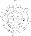
- the oil groove (81) has a configuration illustrated in FIG. 9 .
- an inflow end of high-pressure oil is a proximal portion (81a) and a portion formed around a region where the compression chamber (50) serves as a suction space (50 L) of fluid is a distal portion (81b), at least one of the radial width or the depth of the oil groove (81) is larger in the distal portion (81b) than in the proximal portion (81a).
- the outer peripheral chamfer (82) can be formed at the outer periphery of the oil groove (81), and the inner peripheral chamfer (83) can be formed at the inner periphery of the oil groove (81).
- the outer peripheral chamfer (82) may be formed only at the outer periphery of the oil groove (81) without formation of the inner peripheral chamfer (83) at the inner periphery of the oil groove (81).
- high-pressure lubricating oil in the oil groove (81) also easily flows into the outer portion rather than the inner peripheral portion of the oil groove (81).
- overturn of the orbiting scroll (5) can be reduced with a decrease in sealing property at the outer periphery of the thrust sliding surface (80) in a manner similar to the embodiment. As a result, a decrease in performance of the compressor (1) can be reduced.
- the embodiment may have the following configurations.
- the present disclosure is applied to the scroll compressor (1) with the asymmetrical spiral structure in which the number of turns differs between the fixed lap (42) and the movable lap (52).
- the present disclosure is also applicable to a scroll compressor (1) with a symmetrical spiral structure in which the number of turns of the fixed lap (42) is equal to that of the movable lap (52).
- the outer peripheral chamfer (82) and the inner peripheral chamfer (83) formed in the embodiment do not need to be formed.
- the present disclosure is useful for a sealing structure of a thrust sliding surface between a fixed scroll and an orbiting scroll in a scroll compressor.
Description
- The present disclosure relates to scroll compressors, and particularly to a sealing structure of a thrust sliding surface between a fixed scroll and an orbiting scroll.
- In a typical known scroll compressor, a pressing force toward a fixed scroll is applied to an orbiting scroll so as to prevent the orbiting scroll from moving away from the fixed scroll.
-
Japanese Unexamined Patent Publication No. 2001-214872 - In the scroll compressor, high-pressure oil is supplied to an oil groove formed in a thrust sliding surface between the fixed scroll and the orbiting scroll so that the pressing force is suppressed by a pushback force so as to prevent excessive pressing. The high-pressure oil supplied to the oil groove is distributed over the thrust sliding surface to be used for sealing as well as to lubricate the thrust sliding surface.
-
Japanese Unexamined Patent Publication No. 2010-043641 -
US 2004/265159 A1 discloses a scroll compressor having an oil groove in a fixed slideable contact surface of a fixed scroll, the oil groove extending around the entire circumference of the contact surface. - In a configuration in which an oil groove is formed in a thrust sliding surface between a fixed scroll and an orbiting scroll, when an outer second back-pressure space at the back surface of the orbiting scroll is at an intermediate pressure or a high pressure, oil does not easily spread over the thrust sliding surface, and thus, failures in lubrication and sealing might occur. This is because of the following reasons. When a space around the orbiting scroll is at a low pressure, the pressure difference causes high-pressure oil in the oil groove to flow into a compression chamber at a low pressure and a low-pressure space around the orbiting scroll and to spread over the entire thrust sliding surface. On the other hand, when the second back-pressure space comes to be at an intermediate pressure or a high pressure, almost all the high-pressure oil in the oil groove hardly flows into the second back-pressure space, but flows into the low-pressure compression chamber. Accordingly, oil does not spread to the outer peripheral portion of the oil groove so that no oil film is formed on the outer peripheral portion, and the outer peripheral portion is not sealed. Consequently, refrigerant flows from the second back-pressure space into a low-pressure portion at the suction side of the compression chamber, and the pressure of the second back-pressure space cannot be maintained any more, resulting in the possibility of overturn of the orbiting scroll.
- It is therefore an object of the present disclosure to provide a scroll compressor that adjusts a pressing force of an orbiting scroll to a fixed scroll by forming an oil groove in a thrust sliding surface between the orbiting scroll and the fixed scroll and that can reduce overturn of the orbiting scroll and reduce failures in sealing and lubrication when a back-pressure space around the orbiting scroll is under an intermediate pressure or a high-pressure force.
- The problem of the invention is solved by a scroll compressor according to claim 1.
- The oil groove (81) may have an outer peripheral chamfer (82) and an inner peripheral chamfer (83), and a size of the outer peripheral chamfer (82) may be larger than a size of the inner peripheral chamfer (83).
- An outer peripheral chamfer (82) may beprovided only in an outer peripheral portion of the oil groove (81).
- In these cases, high-pressure oil easily flows into the outer peripheral portion of the oil groove (81), and thus, oil easily spreads to the outer peripheral portion of the oil groove (81). A portion of the oil groove (81) corresponding to an inflow end of high-pressure oil is a proximal portion (81a), a portion of the oil groove (81) formed around the suction space (50 L) of fluid is a distal portion (81b) having a distal end, and at least one of a radial width or a depth of the distal portion (81b) is larger than that of the proximal portion (81a).
- High-pressure oil that has flowed from the proximal portion (81a) into the oil groove (81) has its pressure reduced toward the distal end as the width or depth of the oil groove (81) increases toward the distal portion (81b). In this manner, the pressure difference between the pressure of oil and the pressure at a low-pressure portion at the suction side of the compression chamber (50) decreases, and the amount of oil flowing into the compression chamber (50) decreases.
- In the present disclosure, since the radially outer seal length (L1) is smaller than the radially inner seal length (L2) during orbiting of the orbiting scroll (5), when the outer space at the back surface of the movable end plate (51) is at an intermediate pressure or a high pressure, high-pressure oil in the oil groove (81) does not flow only into the low-pressure space at the suction side of the compression chamber (50) but also easily flows into the outer space (24) at the back surface of the movable end plate (51). Consequently, oil also easily spreads to the outer peripheral portion of the oil groove (81). Thus, a sealing failure is less likely to occur in the outer peripheral portion of the oil groove (81). As a result, the pressure of the back-pressure space at the back surface of the movable end plate (51) can be maintained, and overturn of the orbiting scroll (5) can be reduced, thereby reducing degradation of performance and reliability of the compressor. In addition, since a small amount of high-pressure oil flows from the low-pressure portion into the compression chamber (50), a decrease in efficiency of the compressor can also be reduced.
- The oil groove (81) may have the inner peripheral chamfer (83) and the outer peripheral chamfer (82) such that the size of the outer peripheral chamfer (82) is larger than that of the inner peripheral chamfer (83) or the oil groove (81) may have only the outer peripheral chamfer (82) so that no inner peripheral chamfer (83) is formed. Accordingly, high-pressure oil easily flows into the outer peripheral portion of the oil groove (81). Thus, oil easily spreads to the outer peripheral portion of the oil groove (81), and a sealing failure is less likely to occur in the outer peripheral portion of the oil groove (81).
- The width or the depth of the oil groove (81) increases toward the distal portion (81b). Thus, the pressure of high-pressure oil that has flowed from the proximal portion (81a) into the oil groove (81) decreases toward the distal end. Thus, the pressure difference between the pressure of oil and the pressure of the lower-portion at the suction side of the compression chamber (50) decreases, and a small amount of oil flows into the compression chamber (50) so that operation is performed efficiently. As a result, performance of the compressor is enhanced. In addition, unwanted oil discharge is reduced, thereby enhancing reliability of the compressor.
-
-
FIG. 1 is a vertical sectional view illustrating a scroll compressor according to an embodiment of the present disclosure. -
FIG. 2 is an enlarged sectional view illustrating a compression mechanism illustrated inFIG. 1 . -
FIGS. 3A and 3B illustrate a housing,FIG. 3A is a top view, andFIG. 3B is a sectional view taken along line b-b inFIG. 3A . -
FIG. 4 is a bottom view of a fixed scroll. -
FIG. 5 is a partial enlarged view ofFIG. 4 . -
FIG. 6 is a partial enlarged view of the compression mechanism. -
FIG. 7 is a bottom view of the fixed scroll and illustrates a first engaged state of a fixed lap and a movable lap. -
FIG. 8 is a bottom view of the fixed scroll and illustrates a second engaged state of the fixed lap and the movable lap. -
FIG. 9 is a bottom view of a fixed scroll according to an embodiment according to the invention. - [
FIG. 10] FIG. 10 is a partial enlarged view of a compression mechanism according to a variation. - An embodiment of the present disclosure will be described in detail with reference to the drawings.
-
FIG. 1 is a vertical sectional view illustrating a scroll compressor (1) according to the embodiment, andFIG. 2 is an enlarged view illustrating a main portion ofFIG. 1 . The scroll compressor (1) is connected to a refrigerant circuit (not shown) that performs a refrigeration cycle by circulating refrigerant, and compresses fluid refrigerant. - The scroll compressor (1) is a hermetic compressor including a compression mechanism (14) that sucks and compresses refrigerant and a vertical hollow cylindrical casing (10) that houses the compression mechanism (14).
- The casing (10) is a pressure vessel composed of a casing body (11), an upper wall (12), and a bottom wall (13). The casing body (11) is a cylindrical body having an axial line extending vertically. The upper wall (12) has a bowl shape with an upward convex surface and is hermetically welded to the upper end of the casing body (11). The bottom wall (13) has a bowl shape with a downward convex surface and is hermetically welded to the lower end of the casing body (11).
- The casing (10) accommodates the compression mechanism (14) and an electric motor (6) that drives the compression mechanism (14). The electric motor (6) is located below the compression mechanism (14). The compression mechanism (14) and the electric motor (6) are coupled together by a driving shaft (7) extending vertically in the casing (10).
- An oil sump (15) in which lubricating oil (refrigerating machine oil) is stored is formed at the bottom of the casing (10).
- The upper wall (12) of the casing (10) is provided with a suction pipe (18) for guiding refrigerant in the refrigerant circuit to the compression mechanism (14). The casing body (11) is provided with a discharge pipe (19) for guiding refrigerant in the casing (10) to outside the casing (10).
- The driving shaft (7) includes a main shaft (71), an eccentric portion (72), and a counterweight portion (73). The eccentric portion (72) has a relatively short shaft shape, and projects from the upper end of the main shaft (71). The shaft center of the eccentric portion (72) is eccentric away from the shaft center of the main shaft (71) by a predetermined distance. When the main shaft (71) of the driving shaft (7) rotates, the eccentric portion (72) revolves about the main shaft (71) in an orbit with a radius corresponding to an eccentricity amount from the main shaft (71). The counterweight portion (73) is integrally formed with the main shaft (71) in order to be dynamically balanced with, for example, an orbiting scroll (5), which will be described later, and the eccentric portion (72). In the driving shaft (7), an oil passage (74) extending from the top to the bottom of the driving shaft (7) is formed. The lower end of the driving shaft (7) is immsersed in the oil sump (15).
- The electric motor (6) includes a stator (61) and a rotor (62). The stator (61) is fixed to the casing body (11) by, for example, shrinkage fitting with heat. The rotor (62) is disposed inside the stator (61), and fixed to the main shaft (71) of the driving shaft (7). The rotor (62) is disposed substantially coaxially with the main shaft (71).
- A lower bearing member (21) is provided in a lower portion of the casing (10). The lower bearing member (21) is fixed to a portion near the lower end of the casing body (11). A through hole is formed in a center portion of the lower bearing member (21), and the driving shaft (7) penetrates the through hole. The lower bearing member (21) supports the lower end of the driving shaft (7) such that the driving shaft (7) can rotate.
- The compression mechanism (14) includes a housing (3), a fixed scroll (4), and an orbiting scroll (5). The housing (3) is fixed to the casing body (11). The fixed scroll (4) is disposed on the upper surface of the housing (3). The orbiting scroll (5) is disposed between the fixed scroll (4) and the housing (3).
- As illustrated in
FIG. 3A , which is a top view, andFIG. 3B , which is a b-b sectional view ofFIG. 3A , the housing (3) has a pan shape that is recessed at the center. The housing (3) includes an outer ring (31) and an inner recess (32). - As illustrated in
FIGS. 1 and2 , the housing (3) is fixed to the upper edge of the casing body (11) by press fitting. Specifically, the outer peripheral surface of the ring (31) of the housing (3) is in close contact with the inner peripheral surface of the casing body (11) in the full circumference. The housing (3) divides the inner space of the casing (10) into an upper space (16) and a lower space (17). The upper space (16) is a first space close to the compression mechanism (14). The lower space (17) is a second space housing the electric motor (6). - The housing (3) has a through hole (33) penetrating the housing (3) from the bottom of the recess (32) to the lower end of the housing (3). A bearing metal (20) is inserted in the through hole (33). The driving shaft (7) is inserted through the bearing metal (20). The housing (3) constitutes an upper bearing supporting the upper end of the driving shaft (7) such that the driving shaft (7) can rotate.
- The fixed scroll (4) includes a fixed end plate (41), a fixed lap (42), and an outer wall (43). The fixed lap (42) has an involute spiral wall shape, projects from the front surface (i.e., the lower surface in
FIG. 2 ) of the fixed end plate (41), and is integrated with the fixed end plate (41). The outer wall (43) surrounds the outer periphery of the fixed lap (42) and projects from the front surface of the fixed end plate (41). The end surface of the fixed lap (42) is substantially flush with the end surface of the outer wall (43). The fixed scroll (4) is fixed to the housing (3). - The orbiting scroll (5) includes a movable end plate (51), a movable lap (52), and a boss (53). The movable end plate (51) is in the shape of an approximately circular flat plate. The movable lap (52) has an involute spiral wall shape, projects from the front surface (i.e., the upper surface in
FIG. 2 ) of the movable end plate (51), and is integrated with the movable end plate (51). The boss (53) has a cylindrical shape, and is disposed at the center of the back surface (57) of the movable end plate (51). - The movable lap (52) of the orbiting scroll (5) is engaged with the fixed lap (42) of the fixed scroll (4). In the compression mechanism (14), the fixed lap (42) and the movable lap (52) are engaged with each other to form a compression chamber (50). Around the compression chamber (50), the fixed end plate (41) and the movable end plate (51) are in pressure contact with each other and form a thrust sliding surface (80).
- A portion of the tip surface (i.e., the lower surface in
FIG. 2 ) of the outer wall (43) of the fixed scroll (4) along the inner edge of the outer wall (43) serves as a fixed slidable-contact surface (84) that is in slidable contact with the movable end plate (51) of the orbiting scroll (5). A portion of the front surface (i.e., the upper surface inFIG. 2 ) of the movable end plate (51) of the orbiting scroll (5) surrounding the movable lap (52) serves as a movable slidable-contact surface (85) that is in slidable contact with the fixed slidable-contact surface (84) of the fixed scroll (4). - The outer wall (43) of the fixed scroll (4) has a suction port (25). The suction port (25) is connected to an downstream end of the suction pipe (18). The suction pipe (18) penetrates the upper wall (12) of the casing (10) and extends to the outside of the casing (10). A discharge port (44) penetrating the fixed end plate (41) of the fixed scroll (4) is formed in the center of the fixed end plate (41).
- A high-pressure chamber (45) is formed in the center of the back surface (i.e., the upper surface in
FIG. 2 ) of the fixed end plate (41). The discharge port (44) is open to the high-pressure chamber (45). The high-pressure chamber (45) constitutes a high-pressure space. - The fixed scroll (4) has a first flow passage (46) that communicates with the high-pressure chamber (45). The first flow passage (46) extends radially outward from the high-pressure chamber (45) in the back surface of the fixed end plate (41), extends in the outer wall (43) in an outer peripheral portion of the fixed end plate (41), and is open at the tip surface (i.e., the lower surface in
FIG. 2 ) of the outer wall (43). A cover member (47) covering the high-pressure chamber (45) and the first flow passage (46) is attached to the back surface of the fixed end plate (41). The cover member (47) hermetically separates the high-pressure chamber (45) and the first flow passage (46) from the upper space (16) so that refrigerant gas discharged to the high-pressure chamber (45) and the first flow passage (46) does not leak into the upper space (16). - The fixed end plate (41) is provided with a distribution mechanism that guides refrigerant from the compression chamber (50) to the upper space (16) of the casing (10). The distribution mechanism is configured to allow a back-pressure space (24), which will be described later, and the upper space (16) to communicate with the compression chamber (50) in which refrigerant is being compressed, and includes an intermediate-pressure passage (48) connecting the compression chamber (50) and the upper space (16) to each other. The volume of the compression chamber (50) gradually decreases from when a suction port is completely closed to when the discharge port (44) is open to the compression chamber (50). An end of the intermediate-pressure passage (48) facing the compression chamber (50) is open to the compression chamber (50) at an intermediate pressure having a predetermined volume.
- A reed valve (49) is provided on the back surface of the fixed end plate (41) of the fixed scroll (4). The reed valve (49) is a check valve that opens or closes an opening of the intermediate-pressure passage (48) facing the upper space (16). When the pressure of the compression chamber (50) exceeds the pressure of the upper space (16) by a predetermined value, the reed valve (49) opens, or otherwise the reed valve (49) closes. When the reed valve (49) opens, the compression chamber (50) and the upper space (16) communicate with each other through the intermediate-pressure passage (48). As a result, the pressure of the upper space (16) becomes an intermediate pressure that is higher than the pressure (a suction pressure) of a low-pressure gas refrigerant sucked into the compression chamber (50) and is lower than the pressure (a discharge pressure) of high-pressure gas refrigerant discharged from the compression chamber (50).
- As illustrated in
FIGS. 3A and 3B , the ring (31) of the housing (3) includes four attachment portions (34, 34, ...) for mounting the fixed scroll (4). The attachment portions (34, 34, ...) have screw holes to which the fixed scroll (4) is bolted. - One of the attachment portions (34, 34, ...) has a second flow passage (39) that passes through the ring (31). The second flow passage (39) is disposed so as to communicate with the first flow passage (46) of the fixed scroll (4) when the fixed scroll (4) is attached to the housing (3). Refrigerant gas discharged from the compression chamber (50) to the high-pressure chamber (45) passes through the first flow passage (46) and the second flow passage (39) in this order, and flows into the lower space (17) of the casing (10).
- An inner circumferential wall (35) having a ring shape surrounding the center recess (32) is formed in an inner portion of the ring (31). The inner circumferential wall (35) is lower than that of the attachment portions (34, 34, ...), and is higher than the other portion (except the attachment portions (34, 34, ...)) of the ring (31).
- A seal groove (36) having a ring shape is formed in the tip surface (i.e., the upper surface in
FIG. 2 ) of the iinner circumferential wall (35) and extends along the inner circumferential wall (35). As illustrated inFIG. 2 , an annular seal ring (37) is fitted in the seal groove (36). The seal ring (37) closes a gap between the housing (3) and the movable end plate (51) when being in contact with the back surface (57) of the movable end plate (51) of the orbiting scroll (5). - In the compression mechanism (14), a back-pressure space (22) is formed between the housing (3) and the fixed scroll (4). The back-pressure space (22) is divided by the seal ring (37) into a first back-pressure space (23) at an inner side of the seal ring (37) and a second back-pressure space (24) located at an outer side of the seal ring (37).
- The first back-pressure space (23) communicates with the lower space (17) of the casing (10) through a minute gap formed in a sliding surface between the bearing metal (20) and the driving shaft (7). Although not shown, the housing (3) has an oil discharge passage that is open to the bottom of the first back-pressure space (23). The oil discharge passage allows the first back-pressure space (23) and the lower space (17) to communicate with each other so that lubricating oil in the first back-pressure space (23) can be discharged to the lower space (17).
- In the first back-pressure space (23), the eccentric portion (72) of the driving shaft (7) and the boss (53) of the orbiting scroll (5) are disposed. The eccentric portion (72) is placed in the boss (53) of the orbiting scroll (5) such that the eccentric portion (72) can rotate. The oil passage (74) is open at the upper end of the eccentric portion (72). Specifically, high-pressure lubricating oil is supplied into the boss (53) from the oil passage (74), and the sliding surface between the boss (53) and the eccentric portion (72) is lubricated with the lubricating oil. An in-boss space (58) formed between the upper end surface of the eccentric portion (72) and the back surface (57) of the movable end plate (51) constitutes a high-pressure space.
- The second back-pressure space (24) is a space facing the outer peripheral surface (56) and the back surface (57) of the movable end plate (51), and constitutes an intermediate-pressure space. The second back-pressure space (24) communicates with the upper space (16) through a gap between the housing (3) and the fixed scroll (4). The second back-pressure space (24) may be a high-pressure space.
- The attachment portions (34, 34, ...) of the housing (3) to which the fixed scroll (4) is attached project upward in the ring (31) as illustrated in
FIGS. 3A and 3B . Thus, a gap is formed between the fixed scroll (4) and the ring (31) of the housing (3) in a portion except the attachment portions (34, 34, ...). Through this gap, the second back-pressure space (24) and the upper space (16) communicate with each other. - The second back-pressure space (24) is provided with an Oldham coupling (55). The Oldham coupling (55) is engaged with a key groove (54) formed in the back surface (57) of the movable end plate (51) of the orbiting scroll (5) and key grooves (38, 38) formed in the ring (31) of the housing (3), and controls revolution of the orbiting scroll (5).
- As illustrated in
FIG. 4 , which is a bottom view of the fixed scroll (4),FIG. 5 , which is a partial enlarged view ofFIG. 4 , andFIG. 6 , which is a partial enlarged view of the compression mechanism (14), an oil groove (81) to which high-pressure refrigerating machine oil is supplied is formed in the thrust sliding surface (80) in the compression mechanism (14). Specifically, the oil groove (81) is a groove formed in the fixed slidable-contact surface (84) at the bottom of the fixed end plate (41), and has an arc shape extending along the periphery of the compression chamber (50). As described above, the fixed slidable-contact surface (84) is formed along the inner edge of the lower surface of the outer wall (43) of the fixed scroll (4). Specifically, an envelope (86) of the outer peripheral surface (56) of the movable end plate (51) when the orbiting scroll (5) orbits serves as an outer edge of the fixed slidable-contact surface (84). - On the other hand, an oil supply passage (87) is formed in the movable end plate (51) of the orbiting scroll (5). The oil supply passage (87) is open to the in-boss space (58) at an inflow end thereof, and is open to the movable slidable-contact surface (85) of the movable end plate (51) at an outflow end thereof. When the orbiting scroll (5) revolves, the outflow end of the oil supply passage (87) also orbits in an orbit with a radius corresponding to the orbit of the orbiting scroll (5). In the fixed slidable-contact surface (84), a communication recess (88) for always allowing the oil supply passage (87) and the oil groove (81) to communicate with each other when the orbiting scroll (5) revolves. The communication recess (88) is a middle part of the oil groove (81) that widens radially inward and outward in the orbiting scroll (5). The foregoing configuration causes high-pressure oil in the in-boss space (58) to be always supplied to the oil groove (81) when the orbiting scroll (5) orbits.
-
FIGS. 7 and8 are bottom views of the fixed scroll (4).FIG. 7 illustraes a first engaged state of the fixed lap (42) and the movable lap (52).FIG. 8 illustrates a second engaged state of the fixed lap (42) and the movable lap (52). Specifically,FIG. 7 illustrates a position at which the suction port of the first compression chamber (50a) formed at an outer side of the movable lap (52) is completely closed.FIG. 8 illustrates a position at which the suction port of the second compression chamber (50b) formed at an inner side of the movable lap (52) is completely closed. - In
FIGS. 7 and8 , point A indicates a compression start position (a suction-port closed position) of the first compression chamber (50a). Point B indicates a position at which the orbiting scroll (5) orbits 180° from the compression start position. Between point A and point B, the length of time in which the compression chamber (50) communicates with the suction port (25) is long in a turn of the driving shaft (7), and the region between point A and point B is at a low pressure in more than a half of one turn. - A region from point A to point B is a suction space of fluid at an outer side of the compression chamber (50), i.e., a space to be a low-pressure space (50 L). In this embodiment, in orbiting of the orbiting scroll (5), at least in a portion corresponding to a region (a region from point A to point B) (50 L) to be a suction space of fluid at an outer side of the compression chamber (50), as illustrated in
FIGS. 5 and 6 , an outer seal length (L1) from an outer peripheral edge of the oil groove (81) to an "outer edge (86) of the movable end plate (51)" in the thrust sliding surface (80) is smaller than an inner seal length (L2) from an inner peripheral edge of the oil groove (81) to an "edge of the compression chamber (50)." In this configuration, the "outer edge (86) of the movable end plate (51)" corresponds to the "envelope (86) of the outer peripheral surface (56) of the movable end plate (51) when orbiting scroll (5) orbits" described above, and the "edge of the compression chamber (50)" corresponds to the "inner surface of an outermost fixed lap (42)." - Since the orbiting scroll (5) revolves about the driving shaft (7), the location of the outer peripheral surface (56) of the movable end plate (51) changes in accordance with the revolution, and the outer seal length (L1)of the thrust sliding surface (80) also changes. In this embodiment, the outer seal length (L1) is determined such that the minimum outer seal length (L1) is smaller than the smaller than the inner seal length (L2) in a state in which at least the minimum outer seal length (L1) in the revolution of the orbiting scroll (5) is at minimum when the orbiting scroll (5) orbits. That is, when at least the outer seal length (L1) is at minimum, this outer seal length (L1) is smaller than the inner seal length (L2).
- As illustrated in
FIG. 6 , the oil groove (81) has an outer peripheral chamfer (82) and an inner peripheral chamfer (83). In this embodiment, the size of the outer peripheral chamfer (82) is larger than that of the inner peripheral chamfer (83). - Operation of the scroll compressor (1) will now be described.
- When the electric motor (6) operates, the orbiting scroll (5) of the compression mechanism (14) is driven by the driving shaft (7). The orbiting scroll (5) revolves about the shaft center of the driving shaft (7) in an orbit with a radius corresponding to an eccentricity amount of the eccentric portion (72) with rotation of the orbiting scroll (5) being prevented by the Oldham coupling (55). The revolution of the orbiting scroll (5) causes low-pressure gas refrigerant from the suction pipe (18) to be sucked and compressed in the compression chamber (50) of the compression mechanism (14).
- The compressed refrigerant (i.e., high-pressure gas refrigerant) is discharged from the discharge port (44) of the fixed scroll (4) into the high-pressure chamber (45). The high-pressure refrigerant gas that has flowed into the high-pressure chamber (45) passes through the first flow passage (46) of the fixed scroll (4) and the second flow passage (39) of the housing (3) in this order, and flow out into the lower space (17) of the casing (10). The refrigerant gas that has flowed into the lower space (17) is discharged to the outside of the casing (10) through the discharge pipe (19).
- The lower space (17) of the casing (10) is at a pressure (i.e., a discharge pressure) equal to that of high-pressure gas refrigerant discharged from the compression mechanism (14). Thus, the pressure of lubricating oil stored in the oil sump (15) below the lower space (17) is substantially equal to the discharge pressure.
- High-pressure lubricating oil in the oil sump (15) flows from the lower end to the upper end of the oil passage (74) of the driving shaft (7), and flows into the in-boss space (58) of the orbiting scroll (5) through the opening in the upper end of the eccentric portion (72) of the driving shaft (7). Part of the lubricating oil supplied to the in-boss space (58) lubricates the sliding surface between the boss (53) and the eccentric portion (72), and flows out into the first back-pressure space (23). The lubricating oil that has flowed into the first back-pressure space (23) is discharged to the lower space (17) through the oil discharge passage (not shown). The first back-pressure space (23) communicates with the lower space (17) through the oil discharge passage. Thus, the pressure of the first back-pressure space (23) is substantially equal to the discharge pressure.
- The other part of the lubricating oil supplied to the in-boss space (58) is supplied to the oil groove (81) through the oil supply passage (87). The lubricating oil supplied to the oil groove (81) spreads over the thrust sliding surface (80) and forms an oil film, thereby lubricating the fixed slidable-contact surface (84) and the movable slidable-contact surface (85) and sealing a gap between the compression chamber (50) and the second back-pressure space (24).
- An intermediate-pressure passage (48) is formed in the fixed end plate (41) of the fixed scroll (4). Thus, when the reed valve (49) opens, part of refrigerant that is being compressed in the compression chamber (50) of the compression mechanism (14) flows into the upper space (16) in the casing (10) through the intermediate-pressure passage (48). The upper space (16) communicates with the second back-pressure space (24) at the back surface of the orbiting scroll (5). Thus, the pressure of the second back-pressure space (24) is a pressure (i.e., an intermediate pressure) substantially equal to the pressure of gas refrigerant that is being compressed.
- A fluid pressure (a discharge pressure) in the first back-pressure space (23) and a fluid pressure (an intermediate pressure) in the second back-pressure space (24) are applied onto the back surface (57) of the movable end plate (51) of the orbiting scroll (5). Thus, a pressing force is applied to the orbiting scroll (5) in an axial direction such that the orbiting scroll (5) is pressed against the fixed scroll (4).
- A refrigerant pressure in the compression chamber (50) and a pressure of lubricating oil in the oil groove (81) are applied onto the front surface of the movable end plate (51) of the orbiting scroll (5). Thus, a force in an axial direction (i.e., a repelling force) of urging the orbiting scroll (5) to move away from the fixed scroll (4) acts on the orbiting scroll (5). On the other ahnd, in the compression mechanism (14), a pressing force acts on the orbiting scroll (5), and the orbiting scroll (5) is pressed against the fixed scroll (4) in opposition to the repelling force. Consequently, a tilt (an overturn) of the orbiting scroll (5) due to the repelling force can be reduced.
- If the pressing force is excessively greater than the repelling force, a large friction force acts on the fixed scroll (4) and the orbiting scroll (5) and increases a loss, thereby reducing the efficiency of the scroll compressor (1). On the other hand, if the pressing force is excessively smaller than the repelling force, the orbiting scroll (5) easily tilts, and the amount of leakage of refrigerant from the compression chamber (50) increases, resulting in a decrease in performance of the scroll compressor (1). This causes a local abrasion of the fixed scroll (4) and the orbiting scroll (5) and the reliability of the scroll compressor (1) decreases.
- In the scroll compressor (1) of this embodiment, the ratio between the area on which the discharge pressure acts and the area on which the intermediate pressure acts in the back surface of the orbiting scroll (5), the location of the opening at the compression chamber (50) of the intermediate-pressure passage (48) formed in the fixed scroll (4), and the release pressure of the reed valve (49) in the fixed scroll (4) are appropriately adjusted, thereby applying an appropriate pressing force to the orbiting scroll (5).
- In this manner, the scroll compressor (1) of this embodiment is designed such that an appropriate pressing force acts on the orbiting scroll (5). Thus, the orbiting scroll (5) hardly tilts as long as the scroll compressor (1) operates under operating conditions expected in design and the operating state of, for example, the rotation speed of the electric motor (6) is kept within a range, i.e., in a steady state.
- In addition, in this embodiment, the oil groove (81) in the thrust sliding surface (80) can prevent overturn of the orbiting scroll (5) in the following manner.
- First, the outer second back-pressure space (24) at the back surface of the movable end plate (41) is at an intermediate pressure. Lubricating oil (refrigerating machine oil) in the oil groove (81) flows into the outer second back-pressure space (24) at the intermediate pressure at the back surface of the movable end plate (41) and the low-pressure space (a space communicating with the low-pressure side before the suction port is completely closed) (50 L) at the suction side of the compression chamber (50). In this embodiment, the outer seal length (L1) is smaller than the inner seal length (L2) while the orbiting scroll (5) orbits. Thus, the high-pressure oil in the oil groove (81) flows not only into the low-pressure space (50 L) at the suction side of the compression chamber (50) but also into the outer second back-pressure space (24) at the back surface of the movable end plate (41) easily.
- Accordingly, in this embodiment, oil also easily spreads to an outer peripheral portion of the oil groove (81), and thus, a different in formation state of an oil film does not easily occur between the inner peripheral portion and the outer peripheral portion of the oil groove (81). Thus, a failure is less likely to occur in sealing the thrust sliding surface (80) in the outer peripheral portion of the oil groove (81). As a result, the pressure of the outer second back-pressure space (24) at the back surface of the movable end plate (41) can be maintained, thereby also reducing overturn of the orbiting scroll (5).
- In this embodiment, in a case where at least the outer seal length (L1) is at minimum during orbiting of the orbiting scroll (5), this outer seal length (L1) is smaller than the inner seal length (L2). Thus, the high-pressure oil in the oil groove (81) always easily flows into the second back-pressure space (24) at the back surface of the movable end plate (41) while the orbiting scroll (5) orbits, and accordingly, oil also easily spreads to the outer peripheral portion of the oil groove (81) in the thrust sliding surface (80).
- In particular, the oil groove (81) has the inner peripheral chamfer (83) and the outer peripheral chamfer (82) such that the size of the outer peripheral chamfer (82) is larger than that of the inner peripheral chamfer (83). In this manner, high-pressure oil easily flows into the outer peripheral portion of the oil groove (81), and thus, oil easily spreads to the outer peripheral portion of the oil groove (81) in the thrust sliding surface (80).
- In this embodiment, the outer second back-pressure space (24) at the back surface of the movable end plate (41) is at the intermediate pressure, the pressure difference between the oil groove (81) and the low-pressure space (50 L) at the suction side of the compression chamber (50) is larger than the pressure difference between the oil groove (81) and the second back-pressure space (24), and the outer seal length (L1) is smaller than the inner seal length (L2) while the orbiting scroll (5) orbits. Thus, as described above, high-pressure oil in the oil groove (81) flows not only into the low-pressure space (50 L) at the suction side of the compression chamber (50) but also into the second back-pressure space (24) at the back surface of the movable end plate (41) easily. In the thrust sliding surface (80), oil easily spreads to the outer peripheral portion of the oil groove (81).
- This configuration can reduce the possibility of a sealing failure in the thrust sliding surface (80) in the outer peripheral portion of the oil groove (81). Consequently, the pressure of the second back-pressure space (24) at the back surface of the movable end plate (41) can be maintained, and overturn of the orbiting scroll (5) can be reduced, thereby reducing a decrease in performance and reliability of the compressor (1). Occurrence of a sealing failure in the thrust sliding surface (80) might cause a large amount of high-pressure lubricating oil to flow from the low-pressure space (50 L) into the compression chamber (50). However, in this embodiment, a small amount of high-pressure oil in the oil groove (81) flows from a low-pressure space (50 L) into the compression chamber (50), thereby reducing a decrease in efficiency of the compressor (1).
- In addition, in this embodiment, in a case where at least the outer seal length (L1) is at minimum during orbiting of the orbiting scroll (5), this outer seal length (L1) is smaller than the inner seal length (L2). Thus, high-pressure oil in the oil groove (81) also always flows into the second back-pressure space (24) at the back surface of the movable end plate (41) easily during orbiting of the orbiting scroll (5). At this time, oil always easily spreads to the outer peripheral portion of the oil groove (81). Thus, a sealing failure in the thrust sliding surface (80) is less likely to occur in the outer peripheral portion of the oil groove (81). This also contributes to a decrease in performance degradation caused by overturn of the orbiting scroll (5), and can reduce a decrease in performance and reliability of the compressor (1).
- In particular, since the oil groove (81) has the inner peripheral chamfer (83) and the outer peripheral chamfer (82) and the size of the outer peripheral chamfer (82) is larger than the inner peripheral chamfer (83), high-pressure oil easily spreads to the outer peripheral portion of the oil groove (81). Thus, oil easily spreads to the outer peripheral portion of the oil groove (81) in the thrust sliding surface (80). Since oil easily spreads to the outer peripheral portion of the oil groove (81) and a sealing failure is less likely to occur in the outer peripheral portion of the oil groove (81), it is possible to reduce overturn of the orbiting scroll (5) and a decrease in performance and reliability of the compressor (1) accordingly.
- According to the invention the oil groove (81) has a configuration illustrated in
FIG. 9 . In the oil groove (81) an inflow end of high-pressure oil is a proximal portion (81a) and a portion formed around a region where the compression chamber (50) serves as a suction space (50 L) of fluid is a distal portion (81b), at least one of the radial width or the depth of the oil groove (81) is larger in the distal portion (81b) than in the proximal portion (81a). - In this configuration, high-pressure oil that has flowed from the proximal portion (81a) into the oil groove (81) has its pressure reduced in the distal portion (81b) because the width or the depth of the oil groove (81) is large in the distal portion (81b). Thus, the difference between the pressure of oil and the pressure of a low-pressure space (50 L) at the suction side of the compression chamber (50) decreases, and the amount of oil that flows into the compression chamber (50) decreases. Accordingly, operation can be performed efficiently, thereby enhancing performance of the compressor (1). If a large amount of lubricating oil flowed into the compression chamber (50), the lubricating oil would be discharged to the outside of the compressor (1) together with refrigerant so that unwanted oil discharge would occur easily. On the other hand, occurrence of such unwanted oil discharge can be reduced, thereby enhancing reliability of the compressor (1).
- In the above-described embodiment, the outer peripheral chamfer (82) can be formed at the outer periphery of the oil groove (81), and the inner peripheral chamfer (83) can be formed at the inner periphery of the oil groove (81). Alternatively, as illustrated in
FIG. 10 , the outer peripheral chamfer (82) may be formed only at the outer periphery of the oil groove (81) without formation of the inner peripheral chamfer (83) at the inner periphery of the oil groove (81). In this configuration, high-pressure lubricating oil in the oil groove (81) also easily flows into the outer portion rather than the inner peripheral portion of the oil groove (81). Thus, overturn of the orbiting scroll (5) can be reduced with a decrease in sealing property at the outer periphery of the thrust sliding surface (80) in a manner similar to the embodiment. As a result, a decrease in performance of the compressor (1) can be reduced. - The embodiment may have the following configurations.
- For example, in the embodiment, the present disclosure is applied to the scroll compressor (1) with the asymmetrical spiral structure in which the number of turns differs between the fixed lap (42) and the movable lap (52). However, the present disclosure is also applicable to a scroll compressor (1) with a symmetrical spiral structure in which the number of turns of the fixed lap (42) is equal to that of the movable lap (52).
- The outer peripheral chamfer (82) and the inner peripheral chamfer (83) formed in the embodiment do not need to be formed.
- As described above, the present disclosure is useful for a sealing structure of a thrust sliding surface between a fixed scroll and an orbiting scroll in a scroll compressor.
-
- 1
- scroll compressor
- 4
- fixed scroll
- 5
- orbiting scroll
- 14
- compression mechanism
- 41
- fixed end plate
- 42
- fixed lap
- 50
- compression chamber
- 51
- movable end plate
- 52
- movable lap
- 50L
- low-pressure space (suction space)
- 80
- thrust sliding surface
- 81
- oil groove
- 81a
- proximal portion
- 81b
- distal portion
- 82
- outer peripheral chamfer
- 83
- inner peripheral chamfer
- L1
- outer seal length
- L2
- inner seal length
Claims (1)
- A scroll compressor comprising:a compression mechanism (14) includinga fixed scroll (4) in which a fixed end plate (41) and a spiral fixed lap (42) are integrated, the fixed end plate (41) having a fixed slideable contact surface (84),a radially orbiting scroll (5) in which a movable end plate (51) and a spiral movable lap (52) are integrated, the movable end plate (51) having a moveable slideable contact surface (85), whereinthe fixed lap (42) and the movable lap (52) are engaged with each other and form a compression chamber (50), a suction space (50L) being formed as an outer peripheral portion of the compression chamber (50) communicating with a suction port (25),the fixed slideable contact surface (84) and the movable slideable contact surface (85) are in pressure contact with each other around the compression chamber (50),an oil groove (81) to which high-pressure refrigerating machine oil is supplied is located in the fixed slideable contact surface (84) and extends around part of the compression chamber (50),during orbiting of the orbiting scroll (5), at least in the suction space (50 L), a radially outer seal length (L1) from a radially outer peripheral edge of the oil groove (81) in the fixed slideable contact surface (84) to a radially outer edge (86) of the movable end plate (51) is smaller than a radially inner seal length (L2) from a radially inner peripheral edge of the oil groove (81) to a peripheral edge of the compression chamber (50), characterized in thata portion of the oil groove (81) corresponding to an inflow end of high-pressure oil is a proximal portion (81a),a portion of the oil groove (81) formed around the suction space (50 L) is a distal portion (81b) having a distal end, andat least one of a radial width or a depth of the distal portion (81b) is larger than that of the proximal portion (81a).
Applications Claiming Priority (2)
| Application Number | Priority Date | Filing Date | Title |
|---|---|---|---|
| JP2012134471A JP5516651B2 (en) | 2012-06-14 | 2012-06-14 | Scroll compressor |
| PCT/JP2013/002635 WO2013186974A1 (en) | 2012-06-14 | 2013-04-18 | Scroll compression device |
Publications (3)
| Publication Number | Publication Date |
|---|---|
| EP2863059A1 EP2863059A1 (en) | 2015-04-22 |
| EP2863059A4 EP2863059A4 (en) | 2016-02-17 |
| EP2863059B1 true EP2863059B1 (en) | 2022-08-10 |
Family
ID=49757828
Family Applications (1)
| Application Number | Title | Priority Date | Filing Date |
|---|---|---|---|
| EP13804097.7A Active EP2863059B1 (en) | 2012-06-14 | 2013-04-18 | Scroll compression device |
Country Status (7)
| Country | Link |
|---|---|
| US (1) | US9316225B2 (en) |
| EP (1) | EP2863059B1 (en) |
| JP (1) | JP5516651B2 (en) |
| CN (1) | CN104364529B (en) |
| ES (1) | ES2927470T3 (en) |
| RU (1) | RU2592153C1 (en) |
| WO (1) | WO2013186974A1 (en) |
Families Citing this family (15)
| Publication number | Priority date | Publication date | Assignee | Title |
|---|---|---|---|---|
| WO2014206334A1 (en) | 2013-06-27 | 2014-12-31 | Emerson Climate Technologies, Inc. | Scroll compressor with oil management system |
| JP6425744B2 (en) * | 2015-02-02 | 2018-11-21 | 三菱電機株式会社 | Compressor |
| WO2016173319A1 (en) | 2015-04-30 | 2016-11-03 | 艾默生环境优化技术(苏州)有限公司 | Scroll compressor |
| KR102374062B1 (en) * | 2015-06-23 | 2022-03-14 | 삼성전자주식회사 | Compressor |
| CN105464989B (en) * | 2015-12-24 | 2018-03-23 | 珠海格力节能环保制冷技术研究中心有限公司 | A kind of fueller, there is its screw compressor and control method |
| US11015596B2 (en) | 2016-04-26 | 2021-05-25 | Lg Electronics Inc. | Scroll compressor sealing |
| KR102481672B1 (en) | 2016-04-26 | 2022-12-27 | 엘지전자 주식회사 | Scroll compressor |
| GB2559134B (en) * | 2017-01-25 | 2020-07-29 | Edwards Ltd | Pump assemblies with stator joint seals |
| CN111566350B (en) * | 2018-01-17 | 2022-12-16 | 大金工业株式会社 | Scroll compressor having a scroll compressor with a suction chamber |
| JP7372967B2 (en) * | 2019-05-10 | 2023-11-01 | 三菱重工サーマルシステムズ株式会社 | jig |
| JP6766920B1 (en) * | 2019-05-24 | 2020-10-14 | ダイキン工業株式会社 | Scroll compressor |
| JP6755428B1 (en) * | 2020-06-08 | 2020-09-16 | 日立ジョンソンコントロールズ空調株式会社 | Scroll compressor and refrigeration cycle equipment |
| KR102454721B1 (en) | 2021-02-19 | 2022-10-14 | 엘지전자 주식회사 | Scroll Compressor |
| WO2023026651A1 (en) * | 2021-08-24 | 2023-03-02 | ダイキン工業株式会社 | Scroll compressor and refrigeration device |
| JP7174287B1 (en) * | 2021-08-24 | 2022-11-17 | ダイキン工業株式会社 | Scroll compressor and refrigeration equipment |
Family Cites Families (16)
| Publication number | Priority date | Publication date | Assignee | Title |
|---|---|---|---|---|
| JPS5746001A (en) * | 1980-09-03 | 1982-03-16 | Hitachi Ltd | Scroll fluid device |
| JPS5987291A (en) | 1982-11-10 | 1984-05-19 | Hitachi Ltd | Scroll type fluid machinery |
| JP2543275B2 (en) * | 1991-08-09 | 1996-10-16 | 株式会社日立製作所 | Horizontal scroll compressor |
| RU2046194C1 (en) * | 1991-11-29 | 1995-10-20 | Иван Акимович Сакун | Horizontal spiral machine |
| JP3132339B2 (en) * | 1995-06-19 | 2001-02-05 | 株式会社日立製作所 | Scroll compressor |
| JP3731433B2 (en) | 1999-11-22 | 2006-01-05 | ダイキン工業株式会社 | Scroll compressor |
| JP2003328963A (en) * | 2002-05-16 | 2003-11-19 | Daikin Ind Ltd | Scroll compressor |
| JP4192158B2 (en) * | 2005-03-24 | 2008-12-03 | 日立アプライアンス株式会社 | Hermetic scroll compressor and refrigeration air conditioner |
| US7878777B2 (en) * | 2006-08-25 | 2011-02-01 | Denso Corporation | Scroll compressor having grooved thrust bearing |
| JP5208528B2 (en) * | 2008-01-28 | 2013-06-12 | 日立アプライアンス株式会社 | Hermetic scroll compressor |
| ES2727628T3 (en) | 2008-07-15 | 2019-10-17 | Daikin Ind Ltd | Spiral compressor |
| JP5178668B2 (en) * | 2009-09-11 | 2013-04-10 | 日立アプライアンス株式会社 | Scroll compressor |
| JP5331650B2 (en) * | 2009-10-23 | 2013-10-30 | 日立アプライアンス株式会社 | Scroll compressor |
| CN201568301U (en) * | 2009-12-22 | 2010-09-01 | 大连三洋压缩机有限公司 | Vortex type compressor with floating disc |
| JP5170197B2 (en) * | 2010-09-30 | 2013-03-27 | ダイキン工業株式会社 | Scroll compressor |
| JP5152359B2 (en) * | 2011-03-23 | 2013-02-27 | ダイキン工業株式会社 | Scroll compressor |
-
2012
- 2012-06-14 JP JP2012134471A patent/JP5516651B2/en active Active
-
2013
- 2013-04-18 CN CN201380030613.3A patent/CN104364529B/en active Active
- 2013-04-18 RU RU2015100891/06A patent/RU2592153C1/en active
- 2013-04-18 ES ES13804097T patent/ES2927470T3/en active Active
- 2013-04-18 US US14/407,647 patent/US9316225B2/en active Active
- 2013-04-18 EP EP13804097.7A patent/EP2863059B1/en active Active
- 2013-04-18 WO PCT/JP2013/002635 patent/WO2013186974A1/en active Application Filing
Also Published As
| Publication number | Publication date |
|---|---|
| US9316225B2 (en) | 2016-04-19 |
| US20150147214A1 (en) | 2015-05-28 |
| RU2592153C1 (en) | 2016-07-20 |
| EP2863059A1 (en) | 2015-04-22 |
| CN104364529B (en) | 2015-11-25 |
| JP2013256919A (en) | 2013-12-26 |
| EP2863059A4 (en) | 2016-02-17 |
| CN104364529A (en) | 2015-02-18 |
| BR112014026275A2 (en) | 2017-06-27 |
| WO2013186974A1 (en) | 2013-12-19 |
| JP5516651B2 (en) | 2014-06-11 |
| ES2927470T3 (en) | 2022-11-07 |
Similar Documents
| Publication | Publication Date | Title |
|---|---|---|
| EP2863059B1 (en) | Scroll compression device | |
| KR101529415B1 (en) | Scroll-type compressor | |
| US9903370B2 (en) | Scroll compressor with reduced upsetting moment | |
| EP2295805A1 (en) | Scroll compressor with vapor injection | |
| WO2015022775A1 (en) | Scroll compressor | |
| EP3361047B1 (en) | Scroll compressor | |
| JP2010043641A (en) | Scroll compressor | |
| JP2010101188A (en) | Scroll compressor | |
| JP5691352B2 (en) | Scroll compressor | |
| EP2947320B1 (en) | Scroll compressor | |
| JP2014125908A (en) | Scroll compressor | |
| JP2015105636A (en) | Scroll compressor | |
| JP5660151B2 (en) | Scroll compressor | |
| JP2016156297A (en) | Scroll compressor | |
| EP4102074A1 (en) | Scroll compressor | |
| JP6213639B2 (en) | Scroll compressor | |
| KR101828957B1 (en) | Scroll compressor | |
| JP4301120B2 (en) | Scroll compressor | |
| JP2011137523A (en) | Rotary shaft and compressor | |
| JP2006070711A (en) | Scroll compressor | |
| JP2013087678A (en) | Scroll compressor | |
| JP2016017460A (en) | Scroll compressor |
Legal Events
| Date | Code | Title | Description |
|---|---|---|---|
| PUAI | Public reference made under article 153(3) epc to a published international application that has entered the european phase |
Free format text: ORIGINAL CODE: 0009012 |
|
| 17P | Request for examination filed |
Effective date: 20141105 |
|
| AK | Designated contracting states |
Kind code of ref document: A1 Designated state(s): AL AT BE BG CH CY CZ DE DK EE ES FI FR GB GR HR HU IE IS IT LI LT LU LV MC MK MT NL NO PL PT RO RS SE SI SK SM TR |
|
| AX | Request for extension of the european patent |
Extension state: BA ME |
|
| DAX | Request for extension of the european patent (deleted) | ||
| RA4 | Supplementary search report drawn up and despatched (corrected) |
Effective date: 20160119 |
|
| RIC1 | Information provided on ipc code assigned before grant |
Ipc: F04C 27/00 20060101ALI20160113BHEP Ipc: F04C 29/02 20060101ALI20160113BHEP Ipc: F04C 18/02 20060101AFI20160113BHEP |
|
| RIN1 | Information on inventor provided before grant (corrected) |
Inventor name: NISHIDE, YOUHEI Inventor name: UEKAWA, TAKASHI Inventor name: NAGAHARA, KENJI |
|
| STAA | Information on the status of an ep patent application or granted ep patent |
Free format text: STATUS: EXAMINATION IS IN PROGRESS |
|
| 17Q | First examination report despatched |
Effective date: 20190104 |
|
| STAA | Information on the status of an ep patent application or granted ep patent |
Free format text: STATUS: EXAMINATION IS IN PROGRESS |
|
| GRAP | Despatch of communication of intention to grant a patent |
Free format text: ORIGINAL CODE: EPIDOSNIGR1 |
|
| STAA | Information on the status of an ep patent application or granted ep patent |
Free format text: STATUS: GRANT OF PATENT IS INTENDED |
|
| INTG | Intention to grant announced |
Effective date: 20220603 |
|
| GRAS | Grant fee paid |
Free format text: ORIGINAL CODE: EPIDOSNIGR3 |
|
| GRAA | (expected) grant |
Free format text: ORIGINAL CODE: 0009210 |
|
| STAA | Information on the status of an ep patent application or granted ep patent |
Free format text: STATUS: THE PATENT HAS BEEN GRANTED |
|
| AK | Designated contracting states |
Kind code of ref document: B1 Designated state(s): AL AT BE BG CH CY CZ DE DK EE ES FI FR GB GR HR HU IE IS IT LI LT LU LV MC MK MT NL NO PL PT RO RS SE SI SK SM TR |
|
| REG | Reference to a national code |
Ref country code: GB Ref legal event code: FG4D |
|
| REG | Reference to a national code |
Ref country code: AT Ref legal event code: REF Ref document number: 1510730 Country of ref document: AT Kind code of ref document: T Effective date: 20220815 Ref country code: CH Ref legal event code: EP |
|
| REG | Reference to a national code |
Ref country code: IE Ref legal event code: FG4D |
|
| REG | Reference to a national code |
Ref country code: DE Ref legal event code: R096 Ref document number: 602013082295 Country of ref document: DE |
|
| REG | Reference to a national code |
Ref country code: ES Ref legal event code: FG2A Ref document number: 2927470 Country of ref document: ES Kind code of ref document: T3 Effective date: 20221107 |
|
| REG | Reference to a national code |
Ref country code: NL Ref legal event code: MP Effective date: 20220810 |
|
| REG | Reference to a national code |
Ref country code: LT Ref legal event code: MG9D |
|
| PG25 | Lapsed in a contracting state [announced via postgrant information from national office to epo] |
Ref country code: SE Free format text: LAPSE BECAUSE OF FAILURE TO SUBMIT A TRANSLATION OF THE DESCRIPTION OR TO PAY THE FEE WITHIN THE PRESCRIBED TIME-LIMIT Effective date: 20220810 Ref country code: RS Free format text: LAPSE BECAUSE OF FAILURE TO SUBMIT A TRANSLATION OF THE DESCRIPTION OR TO PAY THE FEE WITHIN THE PRESCRIBED TIME-LIMIT Effective date: 20220810 Ref country code: PT Free format text: LAPSE BECAUSE OF FAILURE TO SUBMIT A TRANSLATION OF THE DESCRIPTION OR TO PAY THE FEE WITHIN THE PRESCRIBED TIME-LIMIT Effective date: 20221212 Ref country code: NO Free format text: LAPSE BECAUSE OF FAILURE TO SUBMIT A TRANSLATION OF THE DESCRIPTION OR TO PAY THE FEE WITHIN THE PRESCRIBED TIME-LIMIT Effective date: 20221110 Ref country code: NL Free format text: LAPSE BECAUSE OF FAILURE TO SUBMIT A TRANSLATION OF THE DESCRIPTION OR TO PAY THE FEE WITHIN THE PRESCRIBED TIME-LIMIT Effective date: 20220810 Ref country code: LV Free format text: LAPSE BECAUSE OF FAILURE TO SUBMIT A TRANSLATION OF THE DESCRIPTION OR TO PAY THE FEE WITHIN THE PRESCRIBED TIME-LIMIT Effective date: 20220810 Ref country code: LT Free format text: LAPSE BECAUSE OF FAILURE TO SUBMIT A TRANSLATION OF THE DESCRIPTION OR TO PAY THE FEE WITHIN THE PRESCRIBED TIME-LIMIT Effective date: 20220810 Ref country code: FI Free format text: LAPSE BECAUSE OF FAILURE TO SUBMIT A TRANSLATION OF THE DESCRIPTION OR TO PAY THE FEE WITHIN THE PRESCRIBED TIME-LIMIT Effective date: 20220810 |
|
| REG | Reference to a national code |
Ref country code: AT Ref legal event code: MK05 Ref document number: 1510730 Country of ref document: AT Kind code of ref document: T Effective date: 20220810 |
|
| PG25 | Lapsed in a contracting state [announced via postgrant information from national office to epo] |
Ref country code: PL Free format text: LAPSE BECAUSE OF FAILURE TO SUBMIT A TRANSLATION OF THE DESCRIPTION OR TO PAY THE FEE WITHIN THE PRESCRIBED TIME-LIMIT Effective date: 20220810 Ref country code: IS Free format text: LAPSE BECAUSE OF FAILURE TO SUBMIT A TRANSLATION OF THE DESCRIPTION OR TO PAY THE FEE WITHIN THE PRESCRIBED TIME-LIMIT Effective date: 20221210 Ref country code: HR Free format text: LAPSE BECAUSE OF FAILURE TO SUBMIT A TRANSLATION OF THE DESCRIPTION OR TO PAY THE FEE WITHIN THE PRESCRIBED TIME-LIMIT Effective date: 20220810 Ref country code: GR Free format text: LAPSE BECAUSE OF FAILURE TO SUBMIT A TRANSLATION OF THE DESCRIPTION OR TO PAY THE FEE WITHIN THE PRESCRIBED TIME-LIMIT Effective date: 20221111 |
|
| PG25 | Lapsed in a contracting state [announced via postgrant information from national office to epo] |
Ref country code: SM Free format text: LAPSE BECAUSE OF FAILURE TO SUBMIT A TRANSLATION OF THE DESCRIPTION OR TO PAY THE FEE WITHIN THE PRESCRIBED TIME-LIMIT Effective date: 20220810 Ref country code: RO Free format text: LAPSE BECAUSE OF FAILURE TO SUBMIT A TRANSLATION OF THE DESCRIPTION OR TO PAY THE FEE WITHIN THE PRESCRIBED TIME-LIMIT Effective date: 20220810 Ref country code: DK Free format text: LAPSE BECAUSE OF FAILURE TO SUBMIT A TRANSLATION OF THE DESCRIPTION OR TO PAY THE FEE WITHIN THE PRESCRIBED TIME-LIMIT Effective date: 20220810 Ref country code: CZ Free format text: LAPSE BECAUSE OF FAILURE TO SUBMIT A TRANSLATION OF THE DESCRIPTION OR TO PAY THE FEE WITHIN THE PRESCRIBED TIME-LIMIT Effective date: 20220810 Ref country code: AT Free format text: LAPSE BECAUSE OF FAILURE TO SUBMIT A TRANSLATION OF THE DESCRIPTION OR TO PAY THE FEE WITHIN THE PRESCRIBED TIME-LIMIT Effective date: 20220810 |
|
| REG | Reference to a national code |
Ref country code: DE Ref legal event code: R097 Ref document number: 602013082295 Country of ref document: DE |
|
| PG25 | Lapsed in a contracting state [announced via postgrant information from national office to epo] |
Ref country code: SK Free format text: LAPSE BECAUSE OF FAILURE TO SUBMIT A TRANSLATION OF THE DESCRIPTION OR TO PAY THE FEE WITHIN THE PRESCRIBED TIME-LIMIT Effective date: 20220810 Ref country code: EE Free format text: LAPSE BECAUSE OF FAILURE TO SUBMIT A TRANSLATION OF THE DESCRIPTION OR TO PAY THE FEE WITHIN THE PRESCRIBED TIME-LIMIT Effective date: 20220810 |
|
| PLBE | No opposition filed within time limit |
Free format text: ORIGINAL CODE: 0009261 |
|
| STAA | Information on the status of an ep patent application or granted ep patent |
Free format text: STATUS: NO OPPOSITION FILED WITHIN TIME LIMIT |
|
| PG25 | Lapsed in a contracting state [announced via postgrant information from national office to epo] |
Ref country code: AL Free format text: LAPSE BECAUSE OF FAILURE TO SUBMIT A TRANSLATION OF THE DESCRIPTION OR TO PAY THE FEE WITHIN THE PRESCRIBED TIME-LIMIT Effective date: 20220810 |
|
| P01 | Opt-out of the competence of the unified patent court (upc) registered |
Effective date: 20230525 |
|
| 26N | No opposition filed |
Effective date: 20230511 |
|
| PGFP | Annual fee paid to national office [announced via postgrant information from national office to epo] |
Ref country code: IT Payment date: 20230426 Year of fee payment: 11 Ref country code: FR Payment date: 20230424 Year of fee payment: 11 Ref country code: ES Payment date: 20230627 Year of fee payment: 11 Ref country code: DE Payment date: 20230420 Year of fee payment: 11 |
|
| PG25 | Lapsed in a contracting state [announced via postgrant information from national office to epo] |
Ref country code: SI Free format text: LAPSE BECAUSE OF FAILURE TO SUBMIT A TRANSLATION OF THE DESCRIPTION OR TO PAY THE FEE WITHIN THE PRESCRIBED TIME-LIMIT Effective date: 20220810 |
|
| PGFP | Annual fee paid to national office [announced via postgrant information from national office to epo] |
Ref country code: GB Payment date: 20230419 Year of fee payment: 11 |
|
| REG | Reference to a national code |
Ref country code: CH Ref legal event code: PL |
|
| PG25 | Lapsed in a contracting state [announced via postgrant information from national office to epo] |
Ref country code: LU Free format text: LAPSE BECAUSE OF NON-PAYMENT OF DUE FEES Effective date: 20230418 |
|
| REG | Reference to a national code |
Ref country code: BE Ref legal event code: MM Effective date: 20230430 |
|
| PG25 | Lapsed in a contracting state [announced via postgrant information from national office to epo] |
Ref country code: MC Free format text: LAPSE BECAUSE OF FAILURE TO SUBMIT A TRANSLATION OF THE DESCRIPTION OR TO PAY THE FEE WITHIN THE PRESCRIBED TIME-LIMIT Effective date: 20220810 |
|
| PG25 | Lapsed in a contracting state [announced via postgrant information from national office to epo] |
Ref country code: MC Free format text: LAPSE BECAUSE OF FAILURE TO SUBMIT A TRANSLATION OF THE DESCRIPTION OR TO PAY THE FEE WITHIN THE PRESCRIBED TIME-LIMIT Effective date: 20220810 Ref country code: LI Free format text: LAPSE BECAUSE OF NON-PAYMENT OF DUE FEES Effective date: 20230430 Ref country code: CH Free format text: LAPSE BECAUSE OF NON-PAYMENT OF DUE FEES Effective date: 20230430 |
|
| REG | Reference to a national code |
Ref country code: IE Ref legal event code: MM4A |
|
| PG25 | Lapsed in a contracting state [announced via postgrant information from national office to epo] |
Ref country code: BE Free format text: LAPSE BECAUSE OF NON-PAYMENT OF DUE FEES Effective date: 20230430 |