JP2014125908A - Scroll compressor - Google Patents
Scroll compressor Download PDFInfo
- Publication number
- JP2014125908A JP2014125908A JP2012281417A JP2012281417A JP2014125908A JP 2014125908 A JP2014125908 A JP 2014125908A JP 2012281417 A JP2012281417 A JP 2012281417A JP 2012281417 A JP2012281417 A JP 2012281417A JP 2014125908 A JP2014125908 A JP 2014125908A
- Authority
- JP
- Japan
- Prior art keywords
- scroll
- pressure
- movable
- space
- fixed
- Prior art date
- Legal status (The legal status is an assumption and is not a legal conclusion. Google has not performed a legal analysis and makes no representation as to the accuracy of the status listed.)
- Pending
Links
Images


Landscapes
- Rotary Pumps (AREA)
Abstract
Description
本発明は、固定スクロールと可動スクロールを有するスクロール圧縮機に関するものである。 The present invention relates to a scroll compressor having a fixed scroll and a movable scroll.
従来より、スクロール圧縮機には、可動スクロールに固定スクロール側への押付け力を付与することで、可動スクロールが固定スクロールから離反することを防止しているものが知られている。 Conventionally, scroll compressors that prevent the movable scroll from separating from the fixed scroll by applying a pressing force to the movable scroll toward the fixed scroll are known.
特許文献1には、その一例として、可動スクロールの鏡板に圧縮室と背圧空間とを連通させる連通路を設け、可動スクロールの背面側の背圧空間に圧縮途中の冷媒ガスを導入するスクロール圧縮機が開示されている。このスクロール圧縮機では、圧縮途中の冷媒ガスの圧力(即ち、中間圧)を可動スクロールの背面に作用させることによって、可動スクロールを固定スクロールへ押し付けている。
In
しかし、上述した従来のスクロール圧縮機は、可動スクロールに充分な押付け力が作用しない状態に陥るおそれがある。以下では、この問題点について説明する。 However, the conventional scroll compressor described above may fall into a state where a sufficient pressing force does not act on the movable scroll. Hereinafter, this problem will be described.
通常、可動スクロールの背面に中間圧を作用させるスクロール圧縮機は、運転状態が一定に保たれる定常状態において、可動スクロールに充分な押付け力が作用するように設計される。つまり、スクロール圧縮機では、可動スクロールに作用する押付け力が、可動スクロールを固定スクロールから引き離そうとする力よりも大きくなるように、可動スクロールの背面のうち中間圧が作用する部分の面積等が設定される。 Usually, a scroll compressor that applies an intermediate pressure to the back surface of the movable scroll is designed so that a sufficient pressing force acts on the movable scroll in a steady state where the operation state is kept constant. In other words, in the scroll compressor, the area of the back surface of the movable scroll where the intermediate pressure acts is set so that the pressing force acting on the movable scroll is larger than the force that pulls the movable scroll away from the fixed scroll. Is done.
ところが、運転状態が変化してゆく過渡状態では、圧縮室から吐出される冷媒の圧力は既に上昇しているにも拘わらず、背圧空間の圧力は未だ充分に上昇していない状況に陥る場合がある。このような状況では、可動スクロールに作用する押付け力が不足し、可動スクロールが固定スクロールに対して傾いてしまう。そして、可動スクロールが傾くと、可動スクロールと固定スクロールのクリアランスが拡大し、圧縮室から漏れ出す冷媒の量が増加してスクロール圧縮機の効率が低下してしまう。 However, in a transient state where the operating state changes, the pressure in the back pressure space has not yet sufficiently increased even though the pressure of the refrigerant discharged from the compression chamber has already increased. There is. In such a situation, the pressing force acting on the movable scroll is insufficient, and the movable scroll is inclined with respect to the fixed scroll. When the movable scroll is tilted, the clearance between the movable scroll and the fixed scroll is increased, the amount of refrigerant leaking from the compression chamber is increased, and the efficiency of the scroll compressor is lowered.
また、可動スクロールが傾くと、中間圧の背圧空間から低圧空間や圧縮行程初期の圧縮室へ冷媒が漏れ出し、背圧空間の圧力が低下してしまう。そして、背圧空間の圧力が低下すると、可動スクロールに作用する押付け力が小さくなり、可動スクロールの傾きが解消されにくくなる。このため、スクロール圧縮機の運転状態が定常状態になった後も可動スクロールが傾いたままとなり、スクロール圧縮機の効率が長時間に亘って低い状態になるおそれがあった。 Further, when the movable scroll is tilted, the refrigerant leaks from the intermediate pressure back pressure space to the low pressure space or the compression chamber at the initial stage of the compression stroke, and the pressure in the back pressure space is reduced. When the pressure in the back pressure space is reduced, the pressing force acting on the movable scroll is reduced, and the inclination of the movable scroll is hardly eliminated. For this reason, even after the operation state of the scroll compressor becomes a steady state, the movable scroll remains inclined, and the efficiency of the scroll compressor may be lowered for a long time.
本発明は、かかる点に鑑みてなされたものであり、その目的は、スクロール圧縮機の運転中に可動スクロールが傾いている時間を短縮し、スクロール圧縮機の効率改善や信頼性向上を図ることにある。 The present invention has been made in view of the above points, and its purpose is to shorten the time during which the movable scroll is tilted during the operation of the scroll compressor, and to improve the efficiency and reliability of the scroll compressor. It is in.
第1の発明は、それぞれに渦巻き状のラップ(42,52)が設けられた固定スクロール(4)及び可動スクロール(5)を有し、上記固定スクロール(4)及び上記可動スクロール(5)のラップ(42,52)が互いに噛み合って圧縮室(50)を形成する圧縮機構(14)と、上記圧縮機構(14)を収容するケーシング(10)とを備え、上記圧縮機構(14)は、低圧流体を上記圧縮室(50)へ吸入して圧縮し、圧縮後の高圧流体を該圧縮室(50)から吐出するスクロール圧縮機を対象とする。そして、上記可動スクロール(5)は、前面から上記ラップ(52)が突出する可動側鏡板部(51)を備え、上記可動側鏡板部(51)の前面は、上記ラップ(52)の周囲を囲む部分が上記固定スクロール(4)の固定側摺接面(84)と摺接する可動側摺接面(85)となる一方、上記圧縮機構(14)は、上記可動スクロール(5)の可動側鏡板部(51)の外周面(56)及び背面(57)に臨む中間圧空間(24)と、圧縮途中の上記圧縮室(50)を上記中間圧空間(24)と連通させるための中間圧通路(48)と、内圧が上記高圧流体の圧力となる高圧空間(45,58)と、一端が上記固定側摺接面(84)と上記可動側摺接面(85)のいずれか一方に開口し、他端が上記高圧空間(45,58)に連通する高圧通路(90)とを備えるものである。 The first invention has a fixed scroll (4) and a movable scroll (5) each provided with a spiral wrap (42, 52), and the fixed scroll (4) and the movable scroll (5) A compression mechanism (14) in which a wrap (42, 52) meshes with each other to form a compression chamber (50); and a casing (10) that houses the compression mechanism (14), and the compression mechanism (14) includes: The present invention is intended for a scroll compressor that sucks and compresses low-pressure fluid into the compression chamber (50) and discharges the compressed high-pressure fluid from the compression chamber (50). The movable scroll (5) includes a movable side end plate portion (51) from which the wrap (52) protrudes from the front surface, and the front side of the movable side end plate portion (51) extends around the wrap (52). The surrounding portion is a movable side sliding contact surface (85) that is in sliding contact with the fixed side sliding contact surface (84) of the fixed scroll (4), while the compression mechanism (14) is the movable side of the movable scroll (5). Intermediate pressure for communicating the intermediate pressure space (24) facing the outer peripheral surface (56) and back surface (57) of the end plate part (51) and the compression chamber (50) in the middle of compression with the intermediate pressure space (24) The passage (48), the high-pressure space (45, 58) in which the internal pressure becomes the pressure of the high-pressure fluid, and one end of the passage (48) to the fixed-side sliding contact surface (84) or the movable-side sliding contact surface (85) A high-pressure passage (90) having an opening and the other end communicating with the high-pressure space (45, 58) is provided.
第1の発明では、圧縮機構(14)に固定スクロール(4)と可動スクロール(5)が設けられる。可動スクロール(5)は、可動側鏡板部(51)を備えており、可動側鏡板部(51)の可動側摺接面(85)が固定スクロール(4)の固定側摺接面(84)と摺接する。 In the first invention, the compression mechanism (14) is provided with the fixed scroll (4) and the movable scroll (5). The movable scroll (5) includes a movable end plate portion (51), and the movable side slide contact surface (85) of the movable side end plate portion (51) is fixed on the fixed side slide contact surface (84) of the fixed scroll (4). And slid.
第1の発明の圧縮機構(14)には、中間圧空間(24)と中間圧通路(48)とが設けられる。中間圧空間(24)は、中間圧通路(48)を介して、圧縮途中の圧縮室(50)と連通可能となっている。このため、中間圧空間(24)の圧力は、圧縮室(50)へ吸入される低圧流体の圧力よりも高く、圧縮室(50)から吐出される高圧流体の圧力よりも低い中間圧となる。中間圧空間(24)内の流体圧力は、可動スクロール(5)の可動側鏡板部(51)の背面(57)に作用する。可動スクロール(5)は、可動側鏡板部(51)の背面(57)に作用する流体圧力によって、固定スクロール(4)に押し付けられる。 The compression mechanism (14) of the first invention is provided with an intermediate pressure space (24) and an intermediate pressure passage (48). The intermediate pressure space (24) can communicate with the compression chamber (50) in the middle of compression via the intermediate pressure passage (48). For this reason, the pressure in the intermediate pressure space (24) is higher than the pressure of the low pressure fluid sucked into the compression chamber (50) and lower than the pressure of the high pressure fluid discharged from the compression chamber (50). . The fluid pressure in the intermediate pressure space (24) acts on the back surface (57) of the movable side end plate portion (51) of the movable scroll (5). The movable scroll (5) is pressed against the fixed scroll (4) by the fluid pressure acting on the back surface (57) of the movable side end plate portion (51).
第1の発明の圧縮機構(14)には、高圧空間(45,58)と高圧通路(90)とが設けられる。高圧通路(90)の一端は、固定側摺接面(84)と可動側摺接面(85)のいずれか一方に開口する。固定側摺接面(84)と可動側摺接面(85)のクリアランスが適正である場合、高圧通路(90)の一端は、塞がれた状態となる。一方、可動スクロール(5)を固定スクロール(4)に押し付ける押付け力が不足すると、可動スクロール(5)が傾く場合がある。可動スクロール(5)が傾くと、固定側摺接面(84)と可動側摺接面(85)のクリアランスが拡大し、高圧通路(90)が中間圧空間(24)と連通する。この状態では、高圧空間(45,58)の流体が高圧通路(90)を通って中間圧空間(24)へ流入し、中間圧空間(24)の圧力が上昇する。中間圧空間(24)の圧力が上昇すると、可動スクロール(5)に作用する押付け力が大きくなり、可動スクロール(5)の傾きが解消される。 The compression mechanism (14) of the first invention is provided with a high pressure space (45, 58) and a high pressure passage (90). One end of the high-pressure passage (90) opens to one of the fixed-side sliding contact surface (84) and the movable-side sliding contact surface (85). When the clearance between the fixed side sliding contact surface (84) and the movable side sliding contact surface (85) is appropriate, one end of the high pressure passage (90) is in a closed state. On the other hand, if the pressing force for pressing the movable scroll (5) against the fixed scroll (4) is insufficient, the movable scroll (5) may tilt. When the movable scroll (5) is tilted, the clearance between the fixed-side sliding contact surface (84) and the movable-side sliding contact surface (85) is expanded, and the high-pressure passage (90) communicates with the intermediate pressure space (24). In this state, the fluid in the high pressure space (45, 58) flows into the intermediate pressure space (24) through the high pressure passage (90), and the pressure in the intermediate pressure space (24) increases. When the pressure in the intermediate pressure space (24) increases, the pressing force acting on the movable scroll (5) increases, and the inclination of the movable scroll (5) is eliminated.
第2の発明は、上記第1の発明において、上記固定側摺接面(84)と上記可動側摺接面(85)のいずれか一方には、上記固定側摺接面(84)又は上記可動側摺接面(85)に開口する上記高圧通路(90)の端部と上記圧縮室(50)の間を横切るように形成され、且つ上記中間圧空間(24)と連通可能な導出用凹部(95)が設けられるものである。 In a second aspect based on the first aspect, either the fixed side sliding contact surface (84) or the movable side sliding contact surface (85) has the fixed side sliding contact surface (84) or the above For lead-out, which is formed so as to cross between the end of the high-pressure passage (90) opened to the movable side sliding contact surface (85) and the compression chamber (50) and can communicate with the intermediate pressure space (24) A recess (95) is provided.
第2の発明では、固定側摺接面(84)と可動側摺接面(85)のいずれか一方に導出用凹部(95)が設けられる。導出用凹部(95)は、固定側摺接面(84)又は可動側摺接面(85)に開口する高圧通路(90)の一端と圧縮室(50)の間を横切るように形成されている。このため、高圧通路(90)から流出して圧縮室(50)へ向かって流れる流体は、その大部分が導出用凹部(95)へ流入する。導出用凹部(95)は、中間圧空間(24)と連通可能になっている。従って、導出用凹部(95)へ流入した流体は、中間圧空間(24)へと導かれる。 In the second aspect of the present invention, the lead-out recess (95) is provided on one of the fixed side sliding contact surface (84) and the movable side sliding contact surface (85). The lead-out recess (95) is formed so as to cross between the compression chamber (50) and one end of the high-pressure passage (90) that opens to the fixed-side sliding contact surface (84) or the movable-side sliding contact surface (85). Yes. For this reason, most of the fluid flowing out from the high-pressure passage (90) and flowing toward the compression chamber (50) flows into the lead-out recess (95). The lead-out recess (95) can communicate with the intermediate pressure space (24). Therefore, the fluid that has flowed into the outlet recess (95) is guided to the intermediate pressure space (24).
第3の発明は、上記第2の発明において、上記導出用凹部(95)は、常に上記中間圧空間(24)と連通しているものである。 In a third aspect based on the second aspect, the lead-out recess (95) is always in communication with the intermediate pressure space (24).
第3の発明では、導出用凹部(95)が常に中間圧空間(24)と連通しているため、導出用凹部(95)へ流入した流体が中間圧空間(24)へ確実に流入する。 In the third aspect of the invention, since the outlet recess (95) is always in communication with the intermediate pressure space (24), the fluid flowing into the outlet recess (95) surely flows into the intermediate pressure space (24).
第4の発明は、上記第1〜第3のいずれか一つの発明において、上記高圧空間(45)は、上記圧縮室(50)から圧縮後の高圧流体が吐出される空間であるものである。 According to a fourth invention, in any one of the first to third inventions, the high-pressure space (45) is a space from which the compressed high-pressure fluid is discharged from the compression chamber (50). .
第4の発明において、可動スクロール(5)が傾くと、圧縮室(50)から吐出された高圧流体の一部が高圧通路(90)を通って中間圧空間(24)へ流入する。このため、可動スクロール(5)が傾くと、短時間に比較的多量の高圧流体が高圧通路(90)を通って中間圧空間(24)へ流入し、中間圧空間(24)の圧力が速やかに上昇する。 In the fourth invention, when the movable scroll (5) is inclined, a part of the high-pressure fluid discharged from the compression chamber (50) flows into the intermediate pressure space (24) through the high-pressure passage (90). For this reason, when the movable scroll (5) tilts, a relatively large amount of high-pressure fluid flows through the high-pressure passage (90) into the intermediate pressure space (24) in a short time, and the pressure in the intermediate pressure space (24) is quickly increased. To rise.
第5の発明は、上記第1〜第3のいずれか一つの発明において、上記高圧通路(90)は、上記固定スクロール(4)に設けられて上記固定側摺接面(84)に開口しているものである。 In a fifth aspect based on any one of the first to third aspects, the high-pressure passage (90) is provided in the fixed scroll (4) and opens to the fixed-side sliding contact surface (84). It is what.
第5の発明では、高圧通路(90)が固定スクロール(4)に設けられ、高圧通路(90)の一端が固定側摺接面(84)に開口する。 In the fifth invention, the high-pressure passage (90) is provided in the fixed scroll (4), and one end of the high-pressure passage (90) opens to the fixed-side sliding contact surface (84).
第6の発明は、上記第1〜第3のいずれか一つの発明において、上記高圧通路(90)は、上記可動スクロール(5)に設けられて上記可動側摺接面(85)に開口しているものである。 In a sixth aspect based on any one of the first to third aspects, the high-pressure passage (90) is provided in the movable scroll (5) and opens to the movable side sliding contact surface (85). It is what.
第6の発明では、高圧通路(90)が可動スクロール(5)に設けられ、高圧通路(90)の一端が可動側摺接面(85)に開口する。 In the sixth aspect of the invention, the high pressure passage (90) is provided in the movable scroll (5), and one end of the high pressure passage (90) opens in the movable side sliding contact surface (85).
第7の発明は、上記第1〜第5のいずれか一つの発明において、上記ケーシング(10)に収容されて上記圧縮機構(14)を駆動する電動機(6)を備える一方、上記圧縮機構(14)は、上記可動スクロール(5)の背面側に配置されて上記ケーシング(10)内の空間を上記圧縮機構(14)側の第1空間(16)と上記電動機(6)側の第2空間(17)に仕切るハウジング(3)を備えており、上記第1空間(16)が上記中間圧空間(24)と連通しているものである。 A seventh invention includes the electric motor (6) housed in the casing (10) and driving the compression mechanism (14) in the first to fifth inventions, while the compression mechanism ( 14) is arranged on the back side of the movable scroll (5), and the space in the casing (10) is divided into a first space (16) on the compression mechanism (14) side and a second on the motor (6) side. A housing (3) partitioned into a space (17) is provided, and the first space (16) communicates with the intermediate pressure space (24).
第7の発明では、圧縮機構(14)にハウジング(3)が設けられる。ケーシング(10)内の空間は、ハウジング(3)によって、第1空間(16)と第2空間(17)に仕切られる。圧縮機構(14)側の第1空間(16)は、中間圧空間(24)と連通している。中間圧空間(24)の圧力が変動すると、それに伴って第1空間(16)の圧力も変動する。 In the seventh invention, the compression mechanism (14) is provided with the housing (3). The space in the casing (10) is divided into a first space (16) and a second space (17) by the housing (3). The first space (16) on the compression mechanism (14) side communicates with the intermediate pressure space (24). When the pressure in the intermediate pressure space (24) varies, the pressure in the first space (16) also varies accordingly.
本発明では、圧縮機構(14)に高圧通路(90)が設けられる。そして、可動スクロール(5)が傾いて可動側摺接面(85)と固定側摺接面(84)のクリアランスが拡大すると、中間圧空間(24)が高圧通路(90)を介して高圧空間(45,58)と連通し、中間圧空間(24)の圧力が上昇する。 In the present invention, the compression mechanism (14) is provided with the high-pressure passage (90). When the movable scroll (5) tilts and the clearance between the movable sliding contact surface (85) and the fixed sliding contact surface (84) increases, the intermediate pressure space (24) becomes the high pressure space via the high pressure passage (90). (45, 58), the pressure in the intermediate pressure space (24) increases.
上述したように、運転状態が変化してゆく過渡状態では、圧縮室(50)から吐出される冷媒の圧力は既に上昇しているにも拘わらず、中間圧空間(24)の圧力は未だ充分に上昇していない状況に陥る場合がある。このような状況では、可動スクロール(5)に作用する押付け力が不足し、可動スクロール(5)が固定スクロール(4)に対して傾いてしまう。また、スクロール圧縮機(1)の運転状態が定常状態になっても可動スクロール(5)に作用する押付け力が不足したままとなり、可動スクロール(5)が傾いた状態が長く続くおそれがある。 As described above, in the transient state where the operating state changes, the pressure in the intermediate pressure space (24) is still sufficient even though the pressure of the refrigerant discharged from the compression chamber (50) has already increased. You may fall into a situation that has not risen. In such a situation, the pressing force acting on the movable scroll (5) is insufficient, and the movable scroll (5) is inclined with respect to the fixed scroll (4). Further, even when the operating state of the scroll compressor (1) becomes a steady state, the pressing force acting on the movable scroll (5) remains insufficient, and the state in which the movable scroll (5) is tilted may continue for a long time.
これに対し、本発明のスクロール圧縮機(1)では、可動スクロール(5)が固定スクロール(4)に対して傾くと、中間圧空間(24)が高圧通路(90)を介して高圧空間(45,58)と連通し、中間圧空間(24)の圧力が上昇する。このため、可動スクロール(5)に作用する押付け力が不足して可動スクロール(5)が傾いた後には、中間圧空間(24)の圧力が速やかに上昇し、可動スクロール(5)に作用する押付け力が速やかに増大することになる。従って、本発明によれば、スクロール圧縮機(1)の運転中に可動スクロール(5)が傾いた場合に、可動スクロール(5)の傾きを速やかに解消することができる。その結果、可動スクロール(5)の傾きに起因する圧縮室(50)からの流体の漏れを抑えることができ、スクロール圧縮機(1)の効率を改善できる。 On the other hand, in the scroll compressor (1) of the present invention, when the movable scroll (5) is tilted with respect to the fixed scroll (4), the intermediate pressure space (24) passes through the high pressure passage (90). 45, 58), the pressure in the intermediate pressure space (24) rises. For this reason, after the pressing force acting on the movable scroll (5) is insufficient and the movable scroll (5) is tilted, the pressure in the intermediate pressure space (24) quickly rises and acts on the movable scroll (5). The pressing force increases rapidly. Therefore, according to the present invention, when the movable scroll (5) is tilted during the operation of the scroll compressor (1), the tilt of the movable scroll (5) can be quickly eliminated. As a result, fluid leakage from the compression chamber (50) due to the inclination of the movable scroll (5) can be suppressed, and the efficiency of the scroll compressor (1) can be improved.
ここで、可動スクロール(5)が傾いた状態において、高圧通路(90)から固定側摺接面(84)と可動側摺接面(85)の隙間へ流出した流体は、可動側鏡板部(51)の外周側に位置する中間圧空間(24)だけでなく、可動側鏡板部(51)の中央側に位置する圧縮室(50)へ向かっても流れる。高圧通路(90)から流出する流体は、圧縮機構(14)で圧縮されて圧縮室(50)から吐出された高圧流体を含む場合がある。その場合、圧縮室(50)から吐出された高圧流体が再び圧縮室(50)へ戻ると、スクロール圧縮機(1)の外部へ吐出される高圧流体の流量が減少し、スクロール圧縮機(1)の効率が低下する。 Here, in the state in which the movable scroll (5) is inclined, the fluid flowing out from the high-pressure passage (90) into the gap between the fixed side sliding contact surface (84) and the movable side sliding contact surface (85) It flows not only to the intermediate pressure space (24) located on the outer peripheral side of 51) but also toward the compression chamber (50) located on the center side of the movable end plate portion (51). The fluid flowing out of the high pressure passage (90) may include high pressure fluid compressed by the compression mechanism (14) and discharged from the compression chamber (50). In that case, when the high-pressure fluid discharged from the compression chamber (50) returns to the compression chamber (50) again, the flow rate of the high-pressure fluid discharged to the outside of the scroll compressor (1) decreases, and the scroll compressor (1 ) Decreases in efficiency.
これに対し、第2の発明では、固定側摺接面(84)と可動側摺接面(85)のいずれか一方に導出用凹部(95)が設けられている。そして、高圧通路(90)から流出して圧縮室(50)へ向かって流れる流体は、その大部分が導出用凹部(95)へ流入して中間圧空間(24)へと導かれる。従って、この発明によれば、高圧通路(90)から流出して圧縮室(50)へ戻る流体の量を削減することができ、高圧通路(90)から流体を流出させることに起因するスクロール圧縮機(1)の効率低下を抑えることができる。 On the other hand, in the second aspect of the present invention, the lead-out recess (95) is provided on either the fixed side sliding contact surface (84) or the movable side sliding contact surface (85). Then, most of the fluid flowing out from the high-pressure passage (90) and flowing toward the compression chamber (50) flows into the outlet recess (95) and is guided to the intermediate pressure space (24). Therefore, according to the present invention, the amount of fluid that flows out from the high-pressure passage (90) and returns to the compression chamber (50) can be reduced, and the scroll compression caused by flowing out the fluid from the high-pressure passage (90). The reduction in efficiency of the machine (1) can be suppressed.
また、第2の発明の圧縮機構(14)では、高圧通路(90)から流出して可動側鏡板部(51)の外周側へ流れる流体だけでなく、高圧通路(90)から流出して圧縮室(50)へ向かって流れる流体も、導出用凹部(95)を通って中間圧空間(24)へ流入する。従って、可動スクロール(5)が傾いた際に中間圧空間(24)の圧力を一層速やかに上昇させることができ、可動スクロール(5)が傾いている時間を一層短縮することができる。 In the compression mechanism (14) of the second invention, not only the fluid flowing out from the high-pressure passage (90) and flowing to the outer peripheral side of the movable end plate portion (51) but also flowing out from the high-pressure passage (90) and compressed The fluid flowing toward the chamber (50) also flows into the intermediate pressure space (24) through the outlet recess (95). Accordingly, when the movable scroll (5) is tilted, the pressure in the intermediate pressure space (24) can be increased more quickly, and the time during which the movable scroll (5) is tilted can be further shortened.
第3の発明では、導出用凹部(95)が常に中間圧空間(24)と連通している。このため、導出用凹部(95)が中間圧空間(24)と間欠的に連通する場合に比べ、導出用凹部(95)へ流入した流体を確実に中間圧空間(24)へ送り込むことができる。 In the third invention, the lead-out recess (95) is always in communication with the intermediate pressure space (24). For this reason, compared with the case where the outlet recess (95) intermittently communicates with the intermediate pressure space (24), the fluid flowing into the outlet recess (95) can be reliably fed into the intermediate pressure space (24). .
第4の発明では、圧縮室(50)から圧縮後の高圧流体が吐出される空間である高圧空間(45)に、高圧通路(90)が連通する。このため、可動スクロール(5)が傾いた状態では、中間圧空間(24)の圧力を速やかに上昇させることができ、その結果、可動スクロール(5)に作用する押付け力を速やかに増大させることができる。従って、この発明によれば、可動スクロール(5)の傾きを速やかに解消することができ、スクロール圧縮機(1)の効率低下を一層確実に抑えることができる。 In the fourth invention, the high-pressure passage (90) communicates with the high-pressure space (45), which is a space from which the compressed high-pressure fluid is discharged from the compression chamber (50). For this reason, when the movable scroll (5) is tilted, the pressure in the intermediate pressure space (24) can be quickly increased, and as a result, the pressing force acting on the movable scroll (5) can be quickly increased. Can do. Therefore, according to the present invention, the inclination of the movable scroll (5) can be quickly eliminated, and the decrease in efficiency of the scroll compressor (1) can be more reliably suppressed.
ここで、スクロール圧縮機(1)では、定常運転状態においても、何らかの要因によって中間圧空間(24)の圧力が変動する場合がある。中間圧空間(24)の圧力が変動すると、可動スクロール(5)に作用する押付け力の大きさも変動し、可動スクロール(5)が傾くおそれがある。 Here, in the scroll compressor (1), the pressure in the intermediate pressure space (24) may fluctuate due to some factor even in the steady operation state. When the pressure in the intermediate pressure space (24) varies, the magnitude of the pressing force acting on the movable scroll (5) also varies, and the movable scroll (5) may be tilted.
一方、第7の発明では、ケーシング(10)内の空間が第1空間(16)と第2空間(17)に仕切られ、第1空間(16)が中間圧空間(24)と連通する。このため、中間圧空間(24)が第1空間(16)と連通していない場合に比べ、中間圧空間(24)の圧力の変動が緩やかとなる。従って、この発明によれば、中間圧空間(24)の圧力の変動を緩やかにすることができ、可動スクロール(5)に作用する押付け力の大きさの変動幅を抑えることができる。その結果、可動スクロール(5)の傾きを抑えることができ、スクロール圧縮機(1)の効率改善や信頼性向上を図ることができる。 On the other hand, in the seventh invention, the space in the casing (10) is partitioned into the first space (16) and the second space (17), and the first space (16) communicates with the intermediate pressure space (24). For this reason, compared with the case where the intermediate pressure space (24) is not in communication with the first space (16), the fluctuation of the pressure in the intermediate pressure space (24) becomes moderate. Therefore, according to the present invention, the fluctuation of the pressure in the intermediate pressure space (24) can be moderated, and the fluctuation range of the magnitude of the pressing force acting on the movable scroll (5) can be suppressed. As a result, the inclination of the movable scroll (5) can be suppressed, and the efficiency and reliability of the scroll compressor (1) can be improved.
以下、本発明の実施形態を図面に基づいて詳細に説明する。 Hereinafter, embodiments of the present invention will be described in detail with reference to the drawings.
《発明の実施形態1》
図1及び図2に示すように、本実施形態に係るスクロール圧縮機(1)は、冷媒が循環して冷凍サイクルを行う冷媒回路(図示省略)に接続され、流体である冷媒を圧縮するものである。
As shown in FIGS. 1 and 2, the scroll compressor (1) according to the present embodiment is connected to a refrigerant circuit (not shown) that circulates refrigerant and performs a refrigeration cycle, and compresses refrigerant that is fluid. It is.
〈スクロール圧縮機の全体構成〉
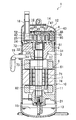
スクロール圧縮機(1)は、冷媒を吸入して圧縮する圧縮機構(14)と、圧縮機構(14)を収容する縦長の中空円筒状に形成されたケーシング(10)とを備えた全密閉型圧縮機である。
<Overall configuration of scroll compressor>
The scroll compressor (1) includes a compression mechanism (14) that sucks and compresses a refrigerant, and a fully-enclosed type that includes a casing (10) formed in a vertically long hollow cylinder that accommodates the compression mechanism (14). It is a compressor.
ケーシング(10)は、ケーシング本体(11)と、上壁部(12)と、底壁部(13)とによって構成された圧力容器である。ケーシング本体(11)は、上下方向に延びる軸線を有する円筒状の胴部である。上壁部(12)は、上方に突出した凸面を有する椀状に形成され、ケーシング本体(11)の上端部に気密状に溶接される。底壁部(13)は、下方に突出した凸面を有する椀状に形成され、ケーシング本体(11)の下端部に気密状に溶接される。 The casing (10) is a pressure vessel constituted by a casing body (11), an upper wall portion (12), and a bottom wall portion (13). The casing body (11) is a cylindrical body having an axis extending in the vertical direction. The upper wall portion (12) is formed in a bowl shape having a convex surface protruding upward, and is welded to the upper end portion of the casing body (11) in an airtight manner. The bottom wall portion (13) is formed in a bowl shape having a convex surface protruding downward, and is welded to the lower end portion of the casing body (11) in an airtight manner.
ケーシング(10)の内部には、圧縮機構(14)と、圧縮機構(14)を駆動する電動機(6)とが収容されている。電動機(6)は、圧縮機構(14)の下方に配置される。圧縮機構(14)と電動機(6)とは、ケーシング(10)内を上下方向に延びるように配置される駆動軸(7)によって連結されている。 Housed in the casing (10) are a compression mechanism (14) and an electric motor (6) that drives the compression mechanism (14). The electric motor (6) is disposed below the compression mechanism (14). The compression mechanism (14) and the electric motor (6) are connected by a drive shaft (7) disposed so as to extend in the vertical direction in the casing (10).
ケーシング(10)の底部には、潤滑油が貯留された油溜まり部(15)が形成されている。 An oil reservoir (15) in which lubricating oil is stored is formed at the bottom of the casing (10).
ケーシング(10)の上壁部(12)には、冷媒回路の冷媒を圧縮機構(14)へ導入するための吸入管(18)が設けられている。また、ケーシング本体(11)には、ケーシング(10)内の冷媒をケーシング(10)外に導出するための吐出管(19)が設けられている。 The upper wall (12) of the casing (10) is provided with a suction pipe (18) for introducing the refrigerant of the refrigerant circuit into the compression mechanism (14). The casing body (11) is provided with a discharge pipe (19) for leading the refrigerant in the casing (10) out of the casing (10).
駆動軸(7)は、主軸部(71)と、偏心部(72)と、カウンタウェイト部(73)とを備えている。偏心部(72)は、比較的短い軸状に形成され、主軸部(71)の上端に突設されている。偏心部(72)の軸心は、主軸部(71)の軸心に対して、所定の距離rだけ偏心している。つまり、この駆動軸(7)では、主軸部(71)に対する偏心部(72)の偏心量が「r」となっている。カウンタウェイト部(73)は、後述する可動スクロール(5)や偏心部(72)等と動的バランスを取るために、主軸部(71)に設けられている。駆動軸(7)の内部には、その上端から下端まで延びる給油路(74)が形成されている。駆動軸(7)の下端部は、油溜まり部(15)に浸漬されている。 The drive shaft (7) includes a main shaft portion (71), an eccentric portion (72), and a counterweight portion (73). The eccentric part (72) is formed in a relatively short shaft shape, and projects from the upper end of the main shaft part (71). The shaft center of the eccentric portion (72) is eccentric by a predetermined distance r with respect to the shaft center of the main shaft portion (71). That is, in the drive shaft (7), the eccentric amount of the eccentric portion (72) with respect to the main shaft portion (71) is “r”. The counterweight portion (73) is provided on the main shaft portion (71) in order to achieve a dynamic balance with a movable scroll (5), an eccentric portion (72) and the like which will be described later. An oil supply path (74) extending from the upper end to the lower end is formed in the drive shaft (7). The lower end of the drive shaft (7) is immersed in the oil reservoir (15).
電動機(6)は、固定子(61)と回転子(62)とにより構成されている。固定子(61)は、焼嵌め等によってケーシング本体(11)に固定されている。回転子(62)は、固定子(61)の内側に配置され、駆動軸(7)の主軸部(71)に固定されている。この回転子(62)は、主軸部(71)と実質的に同軸に配置されている。 The electric motor (6) includes a stator (61) and a rotor (62). The stator (61) is fixed to the casing body (11) by shrink fitting or the like. The rotor (62) is disposed inside the stator (61) and is fixed to the main shaft portion (71) of the drive shaft (7). The rotor (62) is arranged substantially coaxially with the main shaft portion (71).
ケーシング(10)内の下部には、下部軸受部材(21)が設けられている。下部軸受部材(21)は、ケーシング本体(11)の下端付近に固定されている。下部軸受部材(21)の中央部には貫通孔が形成され、この貫通孔に駆動軸(7)が挿通されている。そして、下部軸受部材(21)は、駆動軸(7)の下端部を回転自在に支持する。 A lower bearing member (21) is provided in the lower part of the casing (10). The lower bearing member (21) is fixed near the lower end of the casing body (11). A through hole is formed in the central portion of the lower bearing member (21), and the drive shaft (7) is inserted through the through hole. The lower bearing member (21) rotatably supports the lower end portion of the drive shaft (7).
〈圧縮機構の構成〉
圧縮機構(14)は、ハウジング(3)と、固定スクロール(4)と、可動スクロール(5)とを備えている。ハウジング(3)は、ケーシング本体(11)に固定されている。固定スクロール(4)は、ハウジング(3)の上面に配置されている。可動スクロール(5)は、固定スクロール(4)とハウジング(3)との間に配置されている。
<Configuration of compression mechanism>
The compression mechanism (14) includes a housing (3), a fixed scroll (4), and a movable scroll (5). The housing (3) is fixed to the casing body (11). The fixed scroll (4) is disposed on the upper surface of the housing (3). The movable scroll (5) is disposed between the fixed scroll (4) and the housing (3).
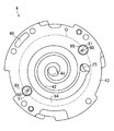
図4に示すように、ハウジング(3)は、中央が凹陥した皿状に形成されている。このハウジング(3)は、外周側の環状部(31)と、内周側の凹部(32)とを備えている。 As shown in FIG. 4, the housing (3) is formed in a dish shape with a recessed center. The housing (3) includes an annular portion (31) on the outer peripheral side and a concave portion (32) on the inner peripheral side.
図1及び図2に示すように、ハウジング(3)は、ケーシング本体(11)の上端縁に圧入固定されている。具体的に、ハウジング(3)の環状部(31)の外周面は、ケーシング本体(11)の内周面と全周に亘って密着している。ハウジング(3)は、ケーシング(10)の内部空間を、上部空間(16)と下部空間(17)に仕切っている。上部空間(16)は、圧縮機構(14)側の第1空間である。下部空間(17)は、電動機(6)が収納された第2空間である。 As shown in FIGS. 1 and 2, the housing (3) is press-fitted and fixed to the upper end edge of the casing body (11). Specifically, the outer peripheral surface of the annular portion (31) of the housing (3) is in close contact with the inner peripheral surface of the casing body (11) over the entire periphery. The housing (3) partitions the internal space of the casing (10) into an upper space (16) and a lower space (17). The upper space (16) is a first space on the compression mechanism (14) side. The lower space (17) is a second space in which the electric motor (6) is accommodated.
ハウジング(3)には、凹部(32)の底部から下端に貫通する貫通孔(33)が形成されている。貫通孔(33)には、軸受メタル(20)が挿入されている。この軸受メタル(20)には、駆動軸(7)が挿通されている。そして、ハウジング(3)は、駆動軸(7)の上端部を回転自在に支持する上部軸受を構成している。 The housing (3) is formed with a through hole (33) penetrating from the bottom of the recess (32) to the lower end. A bearing metal (20) is inserted into the through hole (33). The drive shaft (7) is inserted through the bearing metal (20). The housing (3) constitutes an upper bearing that rotatably supports the upper end portion of the drive shaft (7).
固定スクロール(4)は、固定側鏡板部(41)と、固定側ラップ(42)と、外周壁部(43)とを備えている。固定側ラップ(42)は、インボリュート曲線を描く渦巻き壁状に形成され、固定側鏡板部(41)の前面(図2における下面)から突出している。外周壁部(43)は、固定側ラップ(42)の外周側を囲むように形成され固定側鏡板部(41)の前面から突出している。固定側ラップ(42)の先端面と外周壁部(43)の先端面とは略面一になっている。また、固定スクロール(4)は、ハウジング(3)に固定されている。 The fixed scroll (4) includes a fixed side end plate portion (41), a fixed side wrap (42), and an outer peripheral wall portion (43). The stationary side wrap (42) is formed in a spiral wall shape that draws an involute curve, and projects from the front surface (lower surface in FIG. 2) of the stationary side end plate portion (41). The outer peripheral wall portion (43) is formed so as to surround the outer peripheral side of the fixed side wrap (42) and protrudes from the front surface of the fixed side end plate portion (41). The distal end surface of the fixed side wrap (42) and the distal end surface of the outer peripheral wall portion (43) are substantially flush. The fixed scroll (4) is fixed to the housing (3).
可動スクロール(5)は、可動側鏡板部(51)と、可動側ラップ(52)と、ボス部(53)とを備えている。可動側鏡板部(51)は、概ね円形の平板状に形成されている。固定側ラップ(42)は、インボリュート曲線を描く渦巻き壁状に形成され、可動側鏡板部(51)の前面(図2における上面)から突出している。ボス部(53)は、円筒状に形成され、可動側鏡板部(51)の背面(57)の中央部に配置されている。 The movable scroll (5) includes a movable side end plate portion (51), a movable side wrap (52), and a boss portion (53). The movable side end plate portion (51) is formed in a substantially circular flat plate shape. The fixed side wrap (42) is formed in a spiral wall shape that draws an involute curve, and protrudes from the front surface (upper surface in FIG. 2) of the movable side end plate portion (51). The boss portion (53) is formed in a cylindrical shape, and is arranged at the center of the back surface (57) of the movable side end plate portion (51).
可動スクロール(5)の可動側ラップ(52)は、固定スクロール(4)の固定側ラップ(42)と噛み合わされている。そして、圧縮機構(14)では、固定スクロール(4)の固定側鏡板部(41)及び固定側ラップ(42)と、可動スクロール(5)の可動側鏡板部(51)及び可動側ラップ(52)とに囲まれた圧縮室(50)が形成される。 The movable side wrap (52) of the movable scroll (5) is engaged with the fixed side wrap (42) of the fixed scroll (4). In the compression mechanism (14), the fixed-side end plate portion (41) and the fixed-side wrap (42) of the fixed scroll (4), and the movable-side end plate portion (51) and the movable-side wrap (52) of the movable scroll (5). ) And the compression chamber (50) is formed.
固定スクロール(4)の外周壁部(43)の突端面(図2における下面)は、外周壁部(43)の内周縁に沿った部分が、可動スクロール(5)の可動側鏡板部(51)と摺接する固定側摺接面(84)となっている。また、可動スクロール(5)の可動側鏡板部(51)の前面(図2における上面)では、可動側ラップ(52)の周囲を囲む部分が、固定スクロール(4)の固定側摺接面(84)と摺接する可動側摺接面(85)となっている。 The protruding end surface (the lower surface in FIG. 2) of the outer peripheral wall portion (43) of the fixed scroll (4) has a portion along the inner peripheral edge of the outer peripheral wall portion (43), and the movable end plate portion (51) of the movable scroll (5). ) And the fixed side sliding contact surface (84). Further, on the front surface (upper surface in FIG. 2) of the movable side end plate portion (51) of the movable scroll (5), the portion surrounding the movable side wrap (52) is fixed on the fixed side sliding contact surface of the fixed scroll (4) ( 84) and a movable side sliding contact surface (85).
固定スクロール(4)の外周壁部(43)には、吸入ポート(25)が形成されている。吸入ポート(25)には、吸入管(18)の下流端が接続されている。吸入管(18)は、ケーシング(10)の上壁部(12)を貫通し、ケーシング(10)の外部へ伸びている。また、固定スクロール(4)の固定側鏡板部(41)の中央には、固定側鏡板部(41)を貫通する吐出口(44)が形成されている。 A suction port (25) is formed in the outer peripheral wall (43) of the fixed scroll (4). A downstream end of the suction pipe (18) is connected to the suction port (25). The suction pipe (18) passes through the upper wall (12) of the casing (10) and extends to the outside of the casing (10). A discharge port (44) penetrating the fixed side end plate part (41) is formed in the center of the fixed side end plate part (41) of the fixed scroll (4).
固定側鏡板部(41)の背面(図2における上面)の中央には、高圧チャンバ(45)が形成されている。高圧チャンバ(45)には、吐出口(44)が開口している。この高圧チャンバ(45)は、高圧空間を構成している。 A high-pressure chamber (45) is formed at the center of the back surface (upper surface in FIG. 2) of the fixed-side end plate portion (41). A discharge port (44) is opened in the high pressure chamber (45). The high pressure chamber (45) constitutes a high pressure space.
固定スクロール(4)には、高圧チャンバ(45)に連通する第1流通路(46)が形成されている。第1流通路(46)は、高圧チャンバ(45)から固定側鏡板部(41)の背面において径方向外方に延び、固定側鏡板部(41)の外周部において外周壁部(43)内を延び、外周壁部(43)の突端面(図2における下面)に開口している。固定側鏡板部(41)の背面には、高圧チャンバ(45)及び第1流通路(46)を塞ぐカバー部材(47)が取り付けられている。このカバー部材(47)によって高圧チャンバ(45)及び第1流通路(46)と上部空間(16)とが気密に隔離され、高圧チャンバ(45)及び第1流通路(46)に吐出された冷媒ガスが上部空間(16)に漏洩しないようになっている。 The fixed scroll (4) is formed with a first flow passage (46) communicating with the high-pressure chamber (45). The first flow passage (46) extends radially outward from the high-pressure chamber (45) on the back surface of the fixed-side end plate portion (41), and in the outer peripheral wall portion (43) at the outer peripheral portion of the fixed-side end plate portion (41). And is open to the protruding end surface (the lower surface in FIG. 2) of the outer peripheral wall portion (43). A cover member (47) for closing the high-pressure chamber (45) and the first flow passage (46) is attached to the back surface of the fixed-side end plate portion (41). The cover member (47) hermetically isolates the high pressure chamber (45) and the first flow passage (46) from the upper space (16), and is discharged into the high pressure chamber (45) and the first flow passage (46). The refrigerant gas does not leak into the upper space (16).
固定側鏡板部(41)には、圧縮室(50)からとケーシング(10)の上部空間(16)に冷媒を導く流通機構が設けられている。流通機構は、背圧空間(24)及び上部空間(16)と圧縮途中の圧縮室(50)との間を連通させるためのものであり、圧縮室(50)と上部空間(16)とを繋ぐ中間圧通路(48)を備えている。つまり、圧縮室(50)は、閉じ切り後から吐出口(44)に開口するまで、その容積が徐々に縮小してゆく。そして、中間圧通路(48)の圧縮室(50)側の端部は、所定の容積となった中間圧状態の圧縮室(50)に開口するように設けられている。 The fixed side end plate portion (41) is provided with a flow mechanism for guiding the refrigerant from the compression chamber (50) and to the upper space (16) of the casing (10). The flow mechanism is for communicating between the back pressure space (24) and the upper space (16) and the compression chamber (50) in the middle of compression. The compression chamber (50) and the upper space (16) are connected to each other. An intermediate pressure passage (48) is provided. That is, the volume of the compression chamber (50) is gradually reduced until it is opened to the discharge port (44) after being closed. The end of the intermediate pressure passage (48) on the compression chamber (50) side is provided so as to open to the compression chamber (50) in the intermediate pressure state having a predetermined volume.
固定スクロール(4)の固定側鏡板部(41)の背面には、リード弁(49)が設けられている。このリード弁(49)は、中間圧通路(48)の上部空間(16)側の開口を開閉する逆止弁である。圧縮室(50)の圧力が上部空間(16)の圧力よりも所定値だけ高くなるとリード弁(49)は開き、そうでなければリード弁(49)は閉じる。リード弁(49)が開くと、圧縮室(50)と上部空間(16)が中間圧通路(48)を介して連通する。その結果、上部空間(16)の圧力は、圧縮室(50)へ吸入される低圧ガス冷媒の圧力(吸入圧力)よりも高く、圧縮室(50)から吐出される高圧ガス冷媒の圧力(吐出圧力)よりも低い中間圧となる。 A reed valve (49) is provided on the back surface of the fixed side end plate portion (41) of the fixed scroll (4). The reed valve (49) is a check valve that opens and closes the opening on the upper space (16) side of the intermediate pressure passage (48). When the pressure in the compression chamber (50) becomes higher than the pressure in the upper space (16) by a predetermined value, the reed valve (49) is opened, otherwise, the reed valve (49) is closed. When the reed valve (49) is opened, the compression chamber (50) and the upper space (16) communicate with each other via the intermediate pressure passage (48). As a result, the pressure in the upper space (16) is higher than the pressure (suction pressure) of the low-pressure gas refrigerant sucked into the compression chamber (50), and the pressure (discharge) of the high-pressure gas refrigerant discharged from the compression chamber (50). Intermediate pressure lower than (pressure).
図4に示すように、ハウジング(3)の環状部(31)には、固定スクロール(4)を載せるための取付部(34,34,…)が4つ設けられている。これら取付部(34,34,…)には、ネジ穴が設けられ、固定スクロール(4)がボルトによって固定されている。 As shown in FIG. 4, the annular part (31) of the housing (3) is provided with four attachment parts (34, 34,...) For placing the fixed scroll (4). These mounting portions (34, 34,...) Are provided with screw holes, and the fixed scroll (4) is fixed by bolts.
取付部(34,34,…)のうちの1つには、第2流通路(39)が環状部(31)を貫通するように形成されている。この第2流通路(39)は、固定スクロール(4)がハウジング(3)に取り付けられたときに、固定スクロール(4)の第1流通路(46)と連通する位置に形成されている。圧縮室(50)から高圧チャンバ(45)へ吐出された冷媒ガスは、第1流通路(46)と第2流通路(39)を順に通り、ケーシング(10)の下部空間(17)へ流入する。 In one of the attachment portions (34, 34,...), A second flow passage (39) is formed so as to penetrate the annular portion (31). The second flow passage (39) is formed at a position communicating with the first flow passage (46) of the fixed scroll (4) when the fixed scroll (4) is attached to the housing (3). The refrigerant gas discharged from the compression chamber (50) to the high-pressure chamber (45) flows through the first flow passage (46) and the second flow passage (39) in this order and flows into the lower space (17) of the casing (10). To do.
環状部(31)の内周側には、中央の凹部(32)を囲むように環状に形成された内周壁部(35)が形成されている。この内周壁部(35)は、取付部(34,34,…)よりは低く且つ、環状部(31)のそれ以外の部分よりは高く形成されている。 On the inner peripheral side of the annular portion (31), an inner peripheral wall portion (35) formed in an annular shape so as to surround the central concave portion (32) is formed. The inner peripheral wall portion (35) is formed lower than the attachment portions (34, 34,...) And higher than the other portions of the annular portion (31).
内周壁部(35)の突端面(図2における上面)には、シール溝(36)が内周壁部(35)に沿って環状に形成されている。図2に示すように、シール溝(36)には、環状のシールリング(37)が嵌め込まれている。このシールリング(37)は、可動スクロール(5)の可動側鏡板部(51)の背面(57)に当接し、ハウジング(3)と可動側鏡板部(51)の隙間をシールする。 A seal groove (36) is formed annularly along the inner peripheral wall portion (35) on the protruding end surface (the upper surface in FIG. 2) of the inner peripheral wall portion (35). As shown in FIG. 2, an annular seal ring (37) is fitted in the seal groove (36). The seal ring (37) contacts the back surface (57) of the movable side end plate part (51) of the movable scroll (5) and seals the gap between the housing (3) and the movable side end plate part (51).
圧縮機構(14)では、ハウジング(3)と固定スクロール(4)の間に背圧空間(22)が形成されている。この背圧空間(22)は、シールリング(37)によって、シールリング(37)よりも内周側の第1背圧空間(23)と、シールリング(37)よりも外周側の第2背圧空間(24)とに仕切られている。 In the compression mechanism (14), a back pressure space (22) is formed between the housing (3) and the fixed scroll (4). The back pressure space (22) is divided into a first back pressure space (23) on the inner peripheral side of the seal ring (37) and a second back surface on the outer peripheral side of the seal ring (37) by the seal ring (37). It is partitioned into a pressure space (24).
第1背圧空間(23)は、軸受メタル(20)と駆動軸(7)との隙間を介して、ケーシング(10)の下部空間(17)と連通している。また、図示しないが、ハウジング(3)には、第1背圧空間(23)の底部に開口する排油通路が形成されている。この排油通路は、第1背圧空間(23)を下部空間(17)と連通させ、第1背圧空間(23)内の潤滑油を下部空間(17)へ排出する。 The first back pressure space (23) communicates with the lower space (17) of the casing (10) through a gap between the bearing metal (20) and the drive shaft (7). Although not shown, the housing (3) is formed with an oil drain passage that opens to the bottom of the first back pressure space (23). The drainage passage allows the first back pressure space (23) to communicate with the lower space (17), and the lubricating oil in the first back pressure space (23) is discharged to the lower space (17).
第1背圧空間(23)には、駆動軸(7)の偏心部(72)と可動スクロール(5)のボス部(53)とが位置している。可動スクロール(5)のボス部(53)には、偏心部(72)が回転可能に挿入されている。偏心部(72)の上端には、給油路(74)が開口している。つまり、ボス部(53)内には該給油路(74)から高圧の潤滑油が供給され、ボス部(53)と偏心部(72)の摺動面は潤滑油により潤滑されている。また、偏心部(72)の上端面と可動側鏡板部(51)の背面(57)との間に形成されたボス内空間(58)は、高圧空間を構成している。 The eccentric part (72) of the drive shaft (7) and the boss part (53) of the movable scroll (5) are located in the first back pressure space (23). An eccentric part (72) is rotatably inserted into the boss part (53) of the movable scroll (5). An oil supply passage (74) is opened at the upper end of the eccentric portion (72). That is, high-pressure lubricating oil is supplied from the oil supply passage (74) into the boss portion (53), and the sliding surfaces of the boss portion (53) and the eccentric portion (72) are lubricated by the lubricating oil. The boss inner space (58) formed between the upper end surface of the eccentric portion (72) and the back surface (57) of the movable side end plate portion (51) constitutes a high-pressure space.
第2背圧空間(24)は、可動側鏡板部(51)の外周面(56)と背面(57)に臨む空間であって、中間圧空間を構成している。第2背圧空間(24)は、ハウジング(3)と固定スクロール(4)との間の間隙を介して上部空間(16)と連通している。 The second back pressure space (24) is a space facing the outer peripheral surface (56) and the back surface (57) of the movable side end plate portion (51), and constitutes an intermediate pressure space. The second back pressure space (24) communicates with the upper space (16) through a gap between the housing (3) and the fixed scroll (4).
固定スクロール(4)が取り付けられるハウジング(3)の取付部(34,34,…)は、図4に示すように、環状部(31)において上方に突出している。このため、これら取付部(34,34,…)以外の部分では、固定スクロール(4)とハウジング(3)の環状部(31)との間に間隙が形成される。そして、この間隙を介して、第2背圧空間(24)と上部空間(16)が互いに連通する。 The attachment portions (34, 34,...) Of the housing (3) to which the fixed scroll (4) is attached project upward in the annular portion (31) as shown in FIG. For this reason, a gap is formed between the fixed scroll (4) and the annular portion (31) of the housing (3) at portions other than the mounting portions (34, 34,...). The second back pressure space (24) and the upper space (16) communicate with each other through this gap.
第2背圧空間(24)には、オルダム継手(55)が設けられている。オルダム継手(55)は、可動スクロール(5)の可動側鏡板部(51)の背面(57)に形成されたキー溝(54)と、ハウジング(3)の環状部(31)に形成されたキー溝(38,38)とに係合し、可動スクロール(5)の自転を規制する。 An Oldham coupling (55) is provided in the second back pressure space (24). The Oldham coupling (55) is formed in the keyway (54) formed on the back surface (57) of the movable side end plate portion (51) of the movable scroll (5) and the annular portion (31) of the housing (3). Engages with the keyway (38, 38) to regulate the rotation of the movable scroll (5).
〈高圧通路と導出用溝〉
図2及び図5に示すように、圧縮機構(14)には、高圧通路(90)と、導出用溝(95)とが形成されている。
<High-pressure passage and outlet groove>
As shown in FIGS. 2 and 5, the compression mechanism (14) is formed with a high-pressure passage (90) and a lead-out groove (95).
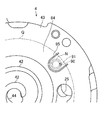
高圧通路(90)は、固定スクロール(4)の外周壁部(43)に形成されている(図2を参照)。高圧通路(90)は、外周壁部(43)を貫通する断面が円形の細長い孔である。高圧通路(90)の一端は、固定側摺接面(84)に開口する開口端(91)となっている。一方、高圧通路(90)の他端は、第1流通路(46)に連通している。そして、高圧通路(90)の他端は、第1流通路(46)を介して、高圧空間である高圧チャンバ(45)に連通している。 The high-pressure passage (90) is formed in the outer peripheral wall (43) of the fixed scroll (4) (see FIG. 2). The high-pressure passage (90) is an elongated hole having a circular cross section that passes through the outer peripheral wall (43). One end of the high-pressure passage (90) is an opening end (91) that opens to the fixed-side sliding contact surface (84). On the other hand, the other end of the high pressure passage (90) communicates with the first flow passage (46). The other end of the high pressure passage (90) communicates with the high pressure chamber (45), which is a high pressure space, via the first flow passage (46).
固定スクロール(4)の固定側摺接面(84)において、高圧通路(90)の開口端(91)は、図5に二点鎖線で示す円Qの内側に配置されている。固定側摺接面(84)のうち円Qの内側の部分は、可動スクロール(5)の可動側摺接面(85)と常に摺接している部分である。従って、高圧通路(90)の開口端(91)は、可動側摺接面(85)と常に対面している。一方、固定側摺接面(84)のうち円Qの外側の部分は、可動側摺接面(85)と間欠的に摺接する部分である。つまり、可動スクロール(5)を駆動する駆動軸(7)が一回転する間において、固定側摺接面(84)のうち円Qの外側の部分は、一時的に第2背圧空間(24)に露出する。 On the fixed side sliding contact surface (84) of the fixed scroll (4), the open end (91) of the high-pressure passage (90) is disposed inside a circle Q indicated by a two-dot chain line in FIG. The portion inside the circle Q of the fixed side sliding contact surface (84) is the portion that is always in sliding contact with the movable side sliding contact surface (85) of the movable scroll (5). Therefore, the open end (91) of the high-pressure passage (90) always faces the movable sliding contact surface (85). On the other hand, the portion of the fixed side sliding contact surface (84) outside the circle Q is a portion that intermittently contacts the movable side sliding contact surface (85). That is, during the rotation of the drive shaft (7) that drives the movable scroll (5), the portion outside the circle Q of the fixed-side sliding contact surface (84) temporarily becomes the second back pressure space (24 ) Exposed.
導出用溝(95)は、固定スクロール(4)の固定側摺接面(84)に形成された凹溝である(図5を参照)。この導出用溝(95)は、高圧通路(90)の開口端(91)の圧縮室(50)側を囲むU字状に形成されている。また、U字状に形成された導出用溝(95)の両端は、図5に示す円Qの外側に位置している。このため、図2及び図3に示すように、導出用溝(95)の両端は、間欠的に第2背圧空間(24)に露出する。このように、導出用溝(95)は、高圧通路(90)の開口端(91)と圧縮室(50)の間を横切るように形成され、第2背圧空間(24)と連通可能になっている。 The lead-out groove (95) is a concave groove formed in the fixed side sliding contact surface (84) of the fixed scroll (4) (see FIG. 5). The lead-out groove (95) is formed in a U shape surrounding the compression chamber (50) side of the open end (91) of the high-pressure passage (90). Further, both ends of the U-shaped lead-out groove (95) are located outside the circle Q shown in FIG. Therefore, as shown in FIGS. 2 and 3, both ends of the lead-out groove (95) are intermittently exposed to the second back pressure space (24). Thus, the lead-out groove (95) is formed so as to cross between the open end (91) of the high-pressure passage (90) and the compression chamber (50), and can communicate with the second back pressure space (24). It has become.
導出用溝(95)は、高圧通路(90)から流出した高圧ガス冷媒を回収して第2背圧空間(24)へ導くための凹溝であって、導出用凹部を構成している。導出用溝(95)は、幅Wが2mm程度、深さDが2mm程度の溝である(図6を参照)。なお、ここで示した導出用溝(95)の幅Wと深さDの値は、いずれも単なる一例である。 The lead-out groove (95) is a concave groove for collecting the high-pressure gas refrigerant flowing out from the high-pressure passage (90) and guiding it to the second back pressure space (24), and constitutes a lead-out recess. The lead-out groove (95) is a groove having a width W of about 2 mm and a depth D of about 2 mm (see FIG. 6). Note that the values of the width W and the depth D of the derivation groove (95) shown here are merely examples.
−スクロール圧縮機の運転動作−
スクロール圧縮機(1)の運転動作について説明する。
-Operation of scroll compressor-
The operation of the scroll compressor (1) will be described.
〈冷媒を圧縮する動作〉
電動機(6)を作動させると、圧縮機構(14)の可動スクロール(5)が駆動軸(7)によって駆動される。可動スクロール(5)は、オルダム継手(55)によって自転を防止されつつ、駆動軸(7)の軸心を中心に公転する。可動スクロール(5)が公転すると、吸入管(18)から流入した低圧ガス冷媒が圧縮機構(14)の圧縮室(50)へ吸入されて圧縮される。
<Operation to compress refrigerant>
When the electric motor (6) is operated, the movable scroll (5) of the compression mechanism (14) is driven by the drive shaft (7). The movable scroll (5) revolves around the axis of the drive shaft (7) while being prevented from rotating by the Oldham coupling (55). When the movable scroll (5) revolves, the low-pressure gas refrigerant flowing from the suction pipe (18) is sucked into the compression chamber (50) of the compression mechanism (14) and compressed.
圧縮が完了した冷媒(即ち、高圧ガス冷媒)は、固定スクロール(4)の吐出口(44)から高圧チャンバ(45)へ吐出される。高圧チャンバ(45)へ流入した高圧の冷媒ガスは、固定スクロール(4)の第1流通路(46)と、ハウジング(3)の第2流通路(39)とを順に通り、ケーシング(10)の下部空間(17)へ流出する。そして、下部空間(17)へ流出した冷媒ガスは、吐出管(19)を通ってケーシング(10)の外部へ吐出される。 The compressed refrigerant (that is, high-pressure gas refrigerant) is discharged from the discharge port (44) of the fixed scroll (4) to the high-pressure chamber (45). The high-pressure refrigerant gas that has flowed into the high-pressure chamber (45) passes through the first flow passage (46) of the fixed scroll (4) and the second flow passage (39) of the housing (3) in this order, and the casing (10) To the lower space (17). Then, the refrigerant gas flowing out into the lower space (17) is discharged to the outside of the casing (10) through the discharge pipe (19).
〈可動スクロールを固定スクロールに押し付ける動作〉
ケーシング(10)の下部空間(17)は、圧縮機構(14)から吐出された高圧ガス冷媒と同等の圧力(即ち、吐出圧力)となっている。従って、下部空間(17)下方の油溜まり部(15)に貯留された潤滑油の圧力も、実質的に吐出圧力と等しくなる。
<Pressing the movable scroll against the fixed scroll>
The lower space (17) of the casing (10) has a pressure equivalent to the high-pressure gas refrigerant discharged from the compression mechanism (14) (that is, discharge pressure). Accordingly, the pressure of the lubricating oil stored in the oil reservoir (15) below the lower space (17) is also substantially equal to the discharge pressure.
油溜まり部(15)に存在する高圧の潤滑油は、駆動軸(7)の給油路(74)の下流端から上流端に向かって流れ、駆動軸(7)の偏心部(72)の上端開口から可動スクロール(5)のボス内空間(58)に流入する。ボス内空間(58)へ供給された潤滑油は、ボス部(53)と偏心部(72)の摺動面を潤滑し、第1背圧空間(23)に流出する。第1背圧空間(23)へ流入した潤滑油は、図外の排油通路を通って下部空間(17)へ排出される。第1背圧空間(23)は、排油通路を介して下部空間(17)と連通している。従って、第1背圧空間(23)の圧力は、吐出圧力と実質的に等しくなる。 The high-pressure lubricating oil present in the oil reservoir (15) flows from the downstream end of the oil supply passage (74) of the drive shaft (7) toward the upstream end, and the upper end of the eccentric portion (72) of the drive shaft (7). It flows into the boss internal space (58) of the movable scroll (5) from the opening. The lubricating oil supplied to the boss inner space (58) lubricates the sliding surfaces of the boss part (53) and the eccentric part (72) and flows out to the first back pressure space (23). The lubricating oil flowing into the first back pressure space (23) is discharged to the lower space (17) through an oil drain passage (not shown). The first back pressure space (23) communicates with the lower space (17) through the oil drainage passage. Accordingly, the pressure in the first back pressure space (23) is substantially equal to the discharge pressure.
固定スクロール(4)の固定側鏡板部(41)には、中間圧通路(48)が形成されている。このため、リード弁(49)が開くと、圧縮機構(14)の圧縮室(50)内で圧縮されつつある冷媒の一部が、中間圧通路(48)を通ってケーシング(10)内の上部空間(16)へ流入する。この上部空間(16)は、可動スクロール(5)の背面側の第2背圧空間(24)と連通している。従って、第2背圧空間(24)の圧力は、圧縮途中のガス冷媒の圧力と同等の圧力(即ち、中間圧)となっている。 An intermediate pressure passage (48) is formed in the fixed side end plate portion (41) of the fixed scroll (4). Therefore, when the reed valve (49) is opened, a part of the refrigerant being compressed in the compression chamber (50) of the compression mechanism (14) passes through the intermediate pressure passage (48) in the casing (10). It flows into the upper space (16). The upper space (16) communicates with the second back pressure space (24) on the back side of the movable scroll (5). Therefore, the pressure in the second back pressure space (24) is equal to the pressure of the gas refrigerant in the middle of compression (ie, intermediate pressure).
可動スクロール(5)の可動側鏡板部(51)の背面(57)には、第1背圧空間(23)内の流体圧力(吐出圧力)と、第2背圧空間(24)内の流体圧力(中間圧)とが作用する。このため、可動スクロール(5)には、可動スクロール(5)を固定スクロール(4)に向かって押圧する軸方向の押付け力が作用する。 On the back surface (57) of the movable side end plate portion (51) of the movable scroll (5), the fluid pressure (discharge pressure) in the first back pressure space (23) and the fluid in the second back pressure space (24) Pressure (intermediate pressure) acts. Therefore, an axial pressing force that presses the movable scroll (5) toward the fixed scroll (4) acts on the movable scroll (5).
ここで、可動スクロール(5)の可動側鏡板部(51)の前面には、圧縮室(50)内の冷媒圧力が作用する。このため、可動スクロール(5)には、可動スクロール(5)を固定スクロール(4)から引き離そうとする軸方向の力(離反力)が作用する。圧縮機構(14)では、可動スクロール(5)に押付け力が作用しており、可動スクロール(5)は、離反力に抗して固定スクロール(4)に押し付けられる。その結果、離反力に起因する可動スクロール(5)の傾斜(転覆)が防止されている。 Here, the refrigerant pressure in the compression chamber (50) acts on the front surface of the movable side end plate portion (51) of the movable scroll (5). For this reason, an axial force (separation force) that tries to separate the movable scroll (5) from the fixed scroll (4) acts on the movable scroll (5). In the compression mechanism (14), a pressing force acts on the movable scroll (5), and the movable scroll (5) is pressed against the fixed scroll (4) against the separation force. As a result, the inclination (rollover) of the movable scroll (5) due to the separation force is prevented.
尚、離反力に対して押付け力が大き過ぎる場合には、固定スクロール(4)と可動スクロール(5)に作用する摩擦力が大きくなり、その摩擦力に起因する損失が増大してスクロール圧縮機(1)の効率が低下してしまう。逆に、離反力に対して押付け力が小さ過ぎる場合には、可動スクロール(5)が傾き易くなり、圧縮室(50)からの冷媒の漏れ量の増加してスクロール圧縮機(1)の性能が低下し、更には、固定スクロール(4)及び可動スクロール(5)の偏摩耗が生じてスクロール圧縮機(1)の信頼性が低下する。 If the pressing force is too large with respect to the separation force, the frictional force acting on the fixed scroll (4) and the movable scroll (5) increases, and the loss due to the frictional force increases and the scroll compressor The efficiency of (1) will decrease. Conversely, if the pressing force is too small relative to the separation force, the movable scroll (5) tends to tilt and the amount of refrigerant leakage from the compression chamber (50) increases, resulting in the performance of the scroll compressor (1). Further, the fixed scroll (4) and the movable scroll (5) are unevenly worn, and the reliability of the scroll compressor (1) is lowered.
本実施形態のスクロール圧縮機(1)では、可動スクロール(5)の背面における、吐出圧力が作用する部分の面積と中間圧が作用する部分の面積との比率、固定スクロール(4)に形成した中間圧通路(48)の圧縮室(50)側の開口位置、固定スクロール(4)に設けたリード弁(49)の開放圧力を適宜調整することによって、適切な押付け力が可動スクロール(5)に付与される。 In the scroll compressor (1) of the present embodiment, the ratio of the area of the portion where the discharge pressure acts to the area of the portion where the intermediate pressure acts on the back of the movable scroll (5) is formed in the fixed scroll (4). By appropriately adjusting the opening position of the intermediate pressure passage (48) on the compression chamber (50) side and the opening pressure of the reed valve (49) provided on the fixed scroll (4), an appropriate pressing force can be applied to the movable scroll (5). To be granted.
〈可動スクロールの傾きを解消するための動作〉
上述したように、本実施形態のスクロール圧縮機(1)は、可動スクロール(5)に作用する押付け力が適切な大きさとなるように設計されている。このため、設計時に想定した運転条件の範囲内で運転されており、且つ電動機(6)の回転速度等の運転状態が一定に保たれた定常状態であれば、可動スクロール(5)が傾くことは殆ど無い。
<Operation to eliminate tilt of movable scroll>
As described above, the scroll compressor (1) of the present embodiment is designed so that the pressing force acting on the movable scroll (5) has an appropriate magnitude. For this reason, the movable scroll (5) tilts if it is operated within the range of operating conditions assumed at the time of design and the operating state such as the rotational speed of the electric motor (6) is kept constant. There is almost no.
ところが、スクロール圧縮機(1)の運転状態が変化しつつある過渡状態(即ち、ある定常状態から別の定常状態へと移行する途中の状態)では、可動スクロール(5)に作用する押付け力が、離反力に対して一時的に不足する場合がある。例えば、運転状態が変化して圧縮室(50)内の冷媒圧力が既に上昇しているにも拘わらず、第2背圧空間(24)内の冷媒圧力(即ち、中間圧)は未だに充分に上昇していない場合には、可動スクロール(5)に作用する押付け力が不足し、可動スクロール(5)が傾くおそれがある。また、スクロール圧縮機(1)の運転状態が定常状態になっても可動スクロール(5)に作用する押付け力が不足したままとなり、可動スクロール(5)が傾いた状態が長く続くおそれがある。 However, in a transient state where the operating state of the scroll compressor (1) is changing (that is, a state in the middle of transition from one steady state to another steady state), the pressing force acting on the movable scroll (5) is , There may be a temporary shortage of separation force. For example, the refrigerant pressure (that is, the intermediate pressure) in the second back pressure space (24) is still sufficiently high even though the refrigerant pressure in the compression chamber (50) has already increased due to the change of the operating state. When it is not raised, the pressing force acting on the movable scroll (5) is insufficient, and the movable scroll (5) may be tilted. Further, even when the operating state of the scroll compressor (1) becomes a steady state, the pressing force acting on the movable scroll (5) remains insufficient, and the state in which the movable scroll (5) is tilted may continue for a long time.
一方、本実施形態のスクロール圧縮機(1)では、圧縮機構(14)に高圧通路(90)が設けられている。このため、スクロール圧縮機(1)の運転中に可動スクロール(5)が傾いた場合には、この可動スクロール(5)の傾きが速やかに解消され、可動スクロール(5)が固定スクロール(4)に押し付けられた状態に復帰する。ここでは、可動スクロール(5)の傾きを解消させる動作について、図6を参照しながら説明する。 On the other hand, in the scroll compressor (1) of the present embodiment, the compression mechanism (14) is provided with a high-pressure passage (90). For this reason, if the movable scroll (5) tilts during operation of the scroll compressor (1), the tilt of the movable scroll (5) is quickly eliminated, and the movable scroll (5) is fixed to the fixed scroll (4). Return to the state where it was pressed. Here, the operation for eliminating the tilt of the movable scroll (5) will be described with reference to FIG.
図6(A)は、可動スクロール(5)が傾いていない状態、即ち、可動スクロール(5)が固定スクロール(4)に押し付けられた正常状態を示している。この正常状態において、固定スクロール(4)の固定側摺接面(84)と可動スクロール(5)の可動側鏡板部(51)とのクリアランスは、固定側摺接面(84)及び可動側摺接面(85)の全体に亘って、概ね一定となっている。また、固定側摺接面(84)と可動側摺接面(85)の間には、潤滑油からなる油膜(81)が形成されている。 FIG. 6A shows a state in which the movable scroll (5) is not inclined, that is, a normal state in which the movable scroll (5) is pressed against the fixed scroll (4). In this normal state, the clearance between the fixed side sliding contact surface (84) of the fixed scroll (4) and the movable side end plate (51) of the movable scroll (5) is the clearance between the fixed side sliding contact surface (84) and the movable side sliding contact. It is generally constant over the entire contact surface (85). An oil film (81) made of lubricating oil is formed between the fixed side sliding contact surface (84) and the movable side sliding contact surface (85).
上述したように、固定側摺接面(84)における高圧通路(90)の開口端(91)は、可動側摺接面(85)と常に対面している。また、固定側摺接面(84)と可動側摺接面(85)の隙間は、油膜(81)によってシールされている。従って、図6(A)に示す正常状態では、高圧通路(90)の開口端(91)が塞がれた状態となり、高圧通路(90)から高圧ガス冷媒は流出しない。 As described above, the open end (91) of the high-pressure passage (90) in the fixed side sliding contact surface (84) always faces the movable side sliding contact surface (85). Further, the gap between the fixed side sliding contact surface (84) and the movable side sliding contact surface (85) is sealed by the oil film (81). Therefore, in the normal state shown in FIG. 6A, the open end (91) of the high-pressure passage (90) is closed, and the high-pressure gas refrigerant does not flow out from the high-pressure passage (90).
一方、図6(B)は、可動スクロール(5)が傾いた転覆状態を示している。この転覆状態において、固定スクロール(4)の固定側摺接面(84)と可動スクロール(5)の可動側鏡板部(51)とのクリアランスは、可動側鏡板部(51)の外周側へ向かって次第に拡大する。また、高圧通路(90)の開口端(91)の周辺では、固定側摺接面(84)と可動側鏡板部(51)のクリアランスが拡大し、油膜(81)によるシール効果が失われる。このため、高圧通路(90)の開口端(91)が、固定側摺接面(84)と可動側鏡板部(51)の隙間を介して第2背圧空間(24)と連通する。そして、高圧チャンバ(45)の高圧ガス冷媒の一部が、高圧通路(90)を通って第2背圧空間(24)へ流入する。 On the other hand, FIG. 6B shows an overturned state in which the movable scroll (5) is tilted. In this overturned state, the clearance between the fixed side sliding contact surface (84) of the fixed scroll (4) and the movable side end plate part (51) of the movable scroll (5) is directed toward the outer peripheral side of the movable side end plate part (51). Gradually expand. Further, in the vicinity of the opening end (91) of the high-pressure passage (90), the clearance between the fixed side sliding contact surface (84) and the movable side end plate portion (51) is enlarged, and the sealing effect by the oil film (81) is lost. For this reason, the open end (91) of the high-pressure passage (90) communicates with the second back pressure space (24) via the gap between the fixed-side sliding contact surface (84) and the movable-side end plate portion (51). A part of the high-pressure gas refrigerant in the high-pressure chamber (45) flows into the second back pressure space (24) through the high-pressure passage (90).
第2背圧空間(24)へ高圧ガス冷媒が流入すると、第2背圧空間(24)の圧力が上昇する。すると、可動側鏡板部(51)の背面(57)に作用する冷媒圧力が上昇し、可動スクロール(5)に作用する押付け力が増大する。その結果、可動スクロール(5)が離反力に抗して固定スクロール(4)に押し付けられた状態となり、可動スクロール(5)の傾きが解消される。即ち、可動側鏡板部(51)は、図6(B)に示す姿勢から同図(A)に示す姿勢へと戻る。 When the high-pressure gas refrigerant flows into the second back pressure space (24), the pressure in the second back pressure space (24) increases. Then, the refrigerant pressure that acts on the back surface (57) of the movable side end plate portion (51) increases, and the pressing force that acts on the movable scroll (5) increases. As a result, the movable scroll (5) is pressed against the fixed scroll (4) against the separating force, and the inclination of the movable scroll (5) is eliminated. That is, the movable side end plate portion (51) returns from the posture shown in FIG. 6 (B) to the posture shown in FIG.
ところで、図6(B)に示すように、高圧通路(90)の開口端(91)から流出した高圧ガス冷媒は、可動側鏡板部(51)の外周側に位置する第2背圧空間(24)だけでなく、可動側鏡板部(51)の中央側に位置する圧縮室(50)へ向かっても流れる。そして、圧縮室(50)から吐出された高圧ガス冷媒が再び圧縮室(50)へ戻ると、吐出管(19)からケーシング(10)の外部へ吐出される高圧ガス冷媒の流量が減少し、スクロール圧縮機(1)の効率が低下する。 By the way, as shown in FIG. 6 (B), the high-pressure gas refrigerant that has flowed out of the open end (91) of the high-pressure passage (90) flows into the second back pressure space (on the outer peripheral side of the movable side end plate portion (51)). 24) As well as flowing toward the compression chamber (50) located on the center side of the movable end plate (51). When the high-pressure gas refrigerant discharged from the compression chamber (50) returns to the compression chamber (50) again, the flow rate of the high-pressure gas refrigerant discharged from the discharge pipe (19) to the outside of the casing (10) decreases. The efficiency of the scroll compressor (1) decreases.
これに対し、本実施形態のスクロール圧縮機(1)では、固定スクロール(4)の固定側摺接面(84)に導出用溝(95)が設けられている。このため、高圧通路(90)の開口端(91)から圧縮室(50)へ流入する高圧ガス冷媒の量が削減される。ここでは、この点について図6(B)を参照しながら説明する。 On the other hand, in the scroll compressor (1) of the present embodiment, a lead-out groove (95) is provided on the fixed side sliding contact surface (84) of the fixed scroll (4). For this reason, the amount of high-pressure gas refrigerant flowing into the compression chamber (50) from the open end (91) of the high-pressure passage (90) is reduced. Here, this point will be described with reference to FIG.
高圧通路(90)の開口端(91)から流出した高圧ガス冷媒の一部は、固定側摺接面(84)と可動側鏡板部(51)の隙間を通って圧縮室(50)側へ流れる。一方、導出用溝(95)の深さDは、固定側摺接面(84)と可動側鏡板部(51)のクリアランスに比べて充分に大きい。このため、固定側摺接面(84)と可動側鏡板部(51)の隙間を通って導出用溝(95)に到達した高圧ガス冷媒は、その大部分が導出用溝(95)内へ流入する。そして、固定側摺接面(84)と可動側鏡板部(51)の狭い隙間を更に流れて圧縮室(50)へ到達する高圧ガス冷媒の量は、極めて僅かとなる。従って、スクロール圧縮機(1)の効率低下が抑制される。 Part of the high-pressure gas refrigerant that has flowed out of the open end (91) of the high-pressure passage (90) passes through the gap between the fixed sliding surface (84) and the movable end plate (51) to the compression chamber (50) side. Flowing. On the other hand, the depth D of the lead-out groove (95) is sufficiently larger than the clearance between the fixed side sliding contact surface (84) and the movable side end plate portion (51). For this reason, most of the high-pressure gas refrigerant that has reached the lead-out groove (95) through the gap between the fixed-side sliding contact surface (84) and the movable-side end plate part (51) enters the lead-out groove (95). Inflow. The amount of high-pressure gas refrigerant that further flows through the narrow gap between the fixed-side sliding contact surface (84) and the movable-side end plate portion (51) and reaches the compression chamber (50) is extremely small. Therefore, a decrease in efficiency of the scroll compressor (1) is suppressed.
導出用溝(95)の端部は、間欠的に第2背圧空間(24)に露出する。このため、導出用溝(95)へ流入した高圧ガス冷媒は、導出用溝(95)の端部から第2背圧空間(24)へ流れ込む。このように、高圧通路(90)の開口端(91)から流出した高圧ガス冷媒は、第2背圧空間(24)へ向かって流れるものだけでなく、圧縮室(50)へ向かって流れるものも、導出用溝(95)を通って第2背圧空間(24)へ流入する。従って、高圧通路(90)の開口端(91)から流出した高圧ガス冷媒の大部分が第2背圧空間(24)へ流入することとなり、第2背圧空間(24)の圧力が一層速やかに上昇する。従って、可動スクロール(5)が傾いている時間が更に短縮される。 The end of the lead-out groove (95) is intermittently exposed to the second back pressure space (24). For this reason, the high-pressure gas refrigerant that has flowed into the outlet groove (95) flows into the second back pressure space (24) from the end of the outlet groove (95). As described above, the high-pressure gas refrigerant flowing out from the open end (91) of the high-pressure passage (90) flows not only toward the second back pressure space (24) but also toward the compression chamber (50). Also flows into the second back pressure space (24) through the outlet groove (95). Therefore, most of the high-pressure gas refrigerant that has flowed out of the open end (91) of the high-pressure passage (90) flows into the second back pressure space (24), and the pressure in the second back pressure space (24) is more rapidly increased. To rise. Therefore, the time during which the movable scroll (5) is tilted is further shortened.
−実施形態1の効果−
本実施形態のスクロール圧縮機(1)では、圧縮機構(14)に高圧通路(90)が設けられる。そして、スクロール圧縮機(1)の運転中に可動スクロール(5)に作用する押付け力が不足して可動スクロール(5)が傾くと、高圧通路(90)の開口端(91)から流出した高圧ガス冷媒が第2背圧空間(24)へ供給される。従って、本実施形態によれば、可動スクロール(5)が傾いた時に第2背圧空間(24)の圧力を速やかに上昇させることができる。このため、可動スクロール(5)に作用する押付け力を速やかに増大させることができ、可動スクロール(5)が傾いている時間を短縮することができる。その結果、可動スクロール(5)の傾きに起因する圧縮室(50)からの冷媒の漏洩を抑えることができ、スクロール圧縮機(1)の効率を向上させることができる。また、可動スクロール(5)の傾きに起因する固定スクロール(4)及び可動スクロール(5)の偏摩耗を抑えることができ、スクロール圧縮機(1)の信頼性を向上させることができる。
-Effect of Embodiment 1-
In the scroll compressor (1) of the present embodiment, the compression mechanism (14) is provided with a high-pressure passage (90). When the movable scroll (5) tilts due to insufficient pressing force acting on the movable scroll (5) during the operation of the scroll compressor (1), the high pressure that flows out from the open end (91) of the high-pressure passage (90) A gas refrigerant is supplied to the second back pressure space (24). Therefore, according to this embodiment, when the movable scroll (5) tilts, the pressure of the second back pressure space (24) can be quickly increased. Therefore, the pressing force acting on the movable scroll (5) can be quickly increased, and the time during which the movable scroll (5) is tilted can be shortened. As a result, refrigerant leakage from the compression chamber (50) due to the inclination of the movable scroll (5) can be suppressed, and the efficiency of the scroll compressor (1) can be improved. Further, uneven wear of the fixed scroll (4) and the movable scroll (5) due to the inclination of the movable scroll (5) can be suppressed, and the reliability of the scroll compressor (1) can be improved.
また、本実施形態の圧縮機構(14)では、固定スクロール(4)の固定側摺接面(84)に導出用溝(95)が形成される。そして、可動スクロール(5)が傾いた状態において、高圧通路(90)の開口端(91)から流出して圧縮室(50)へ向かう高圧ガス冷媒は、導出用溝(95)へ回収されて第2背圧空間(24)へ供給される。従って、本実施形態によれば、高圧通路(90)から流出して圧縮室(50)へ戻る高圧ガス冷媒をの量を削減することができ、高圧通路(90)から高圧ガス冷媒を流出させることに起因するスクロール圧縮機(1)の効率低下を抑えることができる。 Further, in the compression mechanism (14) of the present embodiment, the lead-out groove (95) is formed in the fixed side sliding contact surface (84) of the fixed scroll (4). Then, in a state where the movable scroll (5) is inclined, the high-pressure gas refrigerant flowing out from the open end (91) of the high-pressure passage (90) and going to the compression chamber (50) is collected into the outlet groove (95). It is supplied to the second back pressure space (24). Therefore, according to the present embodiment, the amount of high-pressure gas refrigerant that flows out from the high-pressure passage (90) and returns to the compression chamber (50) can be reduced, and the high-pressure gas refrigerant flows out from the high-pressure passage (90). The reduction in the efficiency of the scroll compressor (1) due to this can be suppressed.
また、本実施形態によれば、高圧通路(90)の開口端(91)から流出した高圧ガス冷媒の大部分を第2背圧空間(24)へ供給することができ、第2背圧空間(24)の圧力を一層速やかに上昇させることができる。従って、本実施形態によれば、可動スクロール(5)が傾いている時間を一層短縮することができる。 Further, according to the present embodiment, most of the high-pressure gas refrigerant flowing out from the open end (91) of the high-pressure passage (90) can be supplied to the second back pressure space (24), and the second back pressure space can be supplied. The pressure of (24) can be increased more rapidly. Therefore, according to this embodiment, the time during which the movable scroll (5) is tilted can be further shortened.
また、本実施形態の高圧通路(90)は、圧縮室(50)から高圧ガス冷媒が吐出される高圧チャンバ(45)に連通している。そして、可動スクロール(5)が傾いた状態になると、高圧チャンバ(45)の高圧ガス冷媒が高圧通路(90)を通って第2背圧空間(24)へ流入する。このため、高圧の冷凍機油が多く存在する空間に高圧通路(90)が連通する場合に比べると、可動スクロール(5)が傾いたときに比較的多量の高圧ガス冷媒を短時間で第2背圧空間(24)へ導入することができる。短時間に比較的多量の高圧ガス冷媒が第2背圧空間(24)へ流入すると、第2背圧空間(24)の圧力が速やかに上昇し、可動スクロール(5)に作用する押付け力が速やかに増大する。従って、本実施形態によれば、可動スクロール(5)の傾きを速やかに解消することができ、可動スクロール(5)の傾きに起因するスクロール圧縮機(1)の効率低下を一層確実に削減できる。 The high-pressure passage (90) of the present embodiment communicates with the high-pressure chamber (45) from which the high-pressure gas refrigerant is discharged from the compression chamber (50). When the movable scroll (5) is tilted, the high-pressure gas refrigerant in the high-pressure chamber (45) flows into the second back pressure space (24) through the high-pressure passage (90). For this reason, compared with the case where the high-pressure passage (90) communicates with a space where a large amount of high-pressure refrigerating machine oil is present, a relatively large amount of high-pressure gas refrigerant can be quickly removed from the second back when the movable scroll (5) is inclined. It can be introduced into the pressure space (24). When a relatively large amount of high-pressure gas refrigerant flows into the second back pressure space (24) in a short time, the pressure in the second back pressure space (24) rises quickly, and the pressing force acting on the movable scroll (5) is increased. Increases quickly. Therefore, according to this embodiment, the inclination of the movable scroll (5) can be quickly eliminated, and the reduction in efficiency of the scroll compressor (1) due to the inclination of the movable scroll (5) can be more reliably reduced. .
ここで、スクロール圧縮機(1)では、定常運転状態においても、何らかの要因によって第2背圧空間(24)の圧力が変動する場合がある。第2背圧空間(24)の圧力が変動すると、可動スクロール(5)に作用する押付け力の大きさも変動し、可動スクロール(5)が傾くおそれがある。 Here, in the scroll compressor (1), the pressure in the second back pressure space (24) may fluctuate due to some factor even in the steady operation state. When the pressure in the second back pressure space (24) varies, the magnitude of the pressing force acting on the movable scroll (5) also varies, and the movable scroll (5) may tilt.
一方、本実施形態のスクロール圧縮機(1)では、ケーシング(10)内の空間が第1空間(16)と第2空間(17)に仕切られ、第1空間(16)が第2背圧空間(24)と連通する。このため、第2背圧空間(24)が第1空間(16)と連通していない場合に比べ、第2背圧空間(24)の圧力の変動が緩やかとなる。従って、本実施形態によれば、第2背圧空間(24)の圧力の変動を緩やかにすることができ、可動スクロール(5)に作用する押付け力の大きさの変動幅を抑えることができる。その結果、可動スクロール(5)の傾きを抑えることができ、スクロール圧縮機(1)の効率改善や信頼性向上を図ることができる。 On the other hand, in the scroll compressor (1) of this embodiment, the space in the casing (10) is partitioned into a first space (16) and a second space (17), and the first space (16) is a second back pressure. It communicates with the space (24). For this reason, compared with the case where the 2nd back pressure space (24) is not connected with the 1st space (16), the fluctuation of the pressure of the 2nd back pressure space (24) becomes gentle. Therefore, according to this embodiment, the fluctuation of the pressure in the second back pressure space (24) can be moderated, and the fluctuation range of the magnitude of the pressing force acting on the movable scroll (5) can be suppressed. . As a result, the inclination of the movable scroll (5) can be suppressed, and the efficiency and reliability of the scroll compressor (1) can be improved.
−実施形態1の変形例1−
本実施形態のスクロール圧縮機(1)において、圧縮機構(14)に設けられた導出用溝(95)の形状は、図5に示すU字状以外の形状であってもよい。
-
In the scroll compressor (1) of the present embodiment, the lead-out groove (95) provided in the compression mechanism (14) may have a shape other than the U-shape shown in FIG.
例えば、導出用溝(95)は、図7に示すような円環状に形成されていてもよい。この円環状の導出用溝(95)は、固定側摺接面(84)における高圧通路(90)の開口端(91)を、その全周に亘って囲っている。また、円環状の導出用溝(95)は、その一部が同図の円Qの内側に位置し、残りの部分が円Qの外側に位置している。図7に示す円Qは、図5に示す円Qと同じものである。従って、図7に示す円環状の導出用溝(95)は、円Qの内側に位置する部分が可動側摺接面(85)と常に対面し、円Qの外側に位置する部分が第2背圧空間(24)に間欠的に露出する。 For example, the lead-out groove (95) may be formed in an annular shape as shown in FIG. The annular lead-out groove (95) surrounds the open end (91) of the high-pressure passage (90) in the fixed-side sliding contact surface (84) over the entire circumference. Further, a part of the annular lead-out groove (95) is located inside the circle Q in the figure, and the remaining part is located outside the circle Q. The circle Q shown in FIG. 7 is the same as the circle Q shown in FIG. Therefore, in the annular lead-out groove (95) shown in FIG. 7, the portion located inside the circle Q always faces the movable sliding surface (85), and the portion located outside the circle Q is the second. It is exposed intermittently to the back pressure space (24).
また、導出用溝(95)は、図8に示すようなV字状に形成されていてもよい。このV字状の導出用溝(95)は、その屈曲部分が固定側摺接面(84)における高圧通路(90)の開口端(91)の内側に位置しており、この屈曲部分から外周壁部(43)の外周側へ向かって延びている。また、V字状の導出用溝(95)は、その一方の端部が同図に示す円Qの外側に位置している。図8に示す円Qは、図5に示す円Qと同じものである。従って、図8に示すV字状の導出用溝(95)は、円Qの内側に位置する部分が可動側摺接面(85)と常に対面し、円Qの外側に位置する部分が第2背圧空間(24)に間欠的に露出する。 Further, the lead-out groove (95) may be formed in a V shape as shown in FIG. The bent portion of the V-shaped lead-out groove (95) is located inside the open end (91) of the high-pressure passage (90) in the fixed side sliding contact surface (84). It extends toward the outer peripheral side of the wall (43). The V-shaped lead-out groove (95) has one end located outside the circle Q shown in FIG. A circle Q shown in FIG. 8 is the same as the circle Q shown in FIG. Therefore, in the V-shaped lead-out groove (95) shown in FIG. 8, the portion located inside the circle Q always faces the movable sliding contact surface (85), and the portion located outside the circle Q is the first. 2 Intermittent exposure to the back pressure space (24).
−実施形態1の変形例2−
本実施形態の圧縮機構(14)には、高圧通路(90)と導出用溝(95)が複数ずつ設けられていてもよい。
-Modification 2 of
The compression mechanism (14) of this embodiment may be provided with a plurality of high-pressure passages (90) and a plurality of outlet grooves (95).
図9に示す固定スクロール(4)では、その外周壁部(43)に高圧通路(90)が二つ設けられている。従って、その固定スクロール(4)の固定側摺接面(84)には、高圧通路(90)の開口端(91)が二つ形成されている。また、その固定側摺接面(84)には、各高圧通路(90)の開口端(91)に対応して、導出用溝(95)が一つずつ形成されている。つまり、同図に示す固定スクロール(4)には、高圧通路(90)と導出用溝(95)が二つずつ設けられている。 In the fixed scroll (4) shown in FIG. 9, two high-pressure passages (90) are provided in the outer peripheral wall (43). Therefore, two open ends (91) of the high-pressure passage (90) are formed on the fixed side sliding contact surface (84) of the fixed scroll (4). Further, on the fixed side sliding contact surface (84), one lead-out groove (95) is formed corresponding to the open end (91) of each high-pressure passage (90). That is, the fixed scroll (4) shown in the figure is provided with two high-pressure passages (90) and two guide grooves (95).
図9に示す固定スクロール(4)の固定側摺接面(84)において、二つの高圧通路(90)の開口端(91)は、それぞれが固定側ラップ(42)を挟んで互いに反対側に配置されている。また、各高圧通路(90)の開口端(91)に対応する導出用溝(95)は、図7に示す導出用溝(95)と同様の円環状に形成されている。つまり、各導出用溝(95)は、対応する高圧通路(90)の開口端(91)を、その全周に亘って囲んでいる。また、各導出用溝(95)は、その一部が図9の円Qの内側に位置し、残りの部分が円Qの外側に位置している。図9に示す円Qは、図5に示す円Qと同じものである。 In the fixed-side sliding contact surface (84) of the fixed scroll (4) shown in FIG. 9, the open ends (91) of the two high-pressure passages (90) are opposite to each other across the fixed-side wrap (42). Has been placed. Further, the lead-out groove (95) corresponding to the open end (91) of each high-pressure passage (90) is formed in an annular shape similar to the lead-out groove (95) shown in FIG. That is, each lead-out groove (95) surrounds the open end (91) of the corresponding high-pressure passage (90) over the entire circumference. Further, a part of each lead-out groove (95) is located inside the circle Q in FIG. 9 and the remaining part is located outside the circle Q. A circle Q shown in FIG. 9 is the same as the circle Q shown in FIG.
−実施形態1の変形例3−
本実施形態の圧縮機構(14)では、導出用溝(95)が第2背圧空間(24)と常に連通していてもよい。
-
In the compression mechanism (14) of the present embodiment, the outlet groove (95) may always communicate with the second back pressure space (24).
図10は、本変形例を図2に示す圧縮機構(14)に適用したものを示す。図2に示す圧縮機構(14)の導出用溝(95)は、U字状に形成されている(図5を参照)。そして、図10に示す本変形例の導出用溝(95)は、図2に示す導出用溝(95)よりも外周壁部(43)の外周側へ伸びている。そして、本変形例の導出用溝(95)の両端部は、可動スクロール(5)の位置に拘わらず、常に第2背圧空間(24)に露出する。 FIG. 10 shows the modification applied to the compression mechanism (14) shown in FIG. The lead-out groove (95) of the compression mechanism (14) shown in FIG. 2 is formed in a U shape (see FIG. 5). And the derivation | leading-out groove | channel (95) of this modification shown in FIG. 10 is extended in the outer peripheral side of the outer peripheral wall part (43) rather than the derivation | leading-out groove | channel (95) shown in FIG. Then, both end portions of the lead-out groove (95) of this modification are always exposed to the second back pressure space (24) regardless of the position of the movable scroll (5).
《発明の実施形態2》
本発明の実施形態2について説明する。本実施形態のスクロール圧縮機(1)は、実施形態1のスクロール圧縮機(1)において、圧縮機構(14)の構成を変更したものである。ここでは、本実施形態のスクロール圧縮機(1)について、実施形態1と異なる点を説明する。
<< Embodiment 2 of the Invention >>
A second embodiment of the present invention will be described. The scroll compressor (1) of the present embodiment is obtained by changing the configuration of the compression mechanism (14) in the scroll compressor (1) of the first embodiment. Here, a different point from
図11に示すように、本実施形態の圧縮機構(14)では、高圧通路(90)と導出用溝(95)が、固定スクロール(4)ではなく可動スクロール(5)に設けられている。 As shown in FIG. 11, in the compression mechanism (14) of the present embodiment, the high-pressure passage (90) and the lead-out groove (95) are provided in the movable scroll (5) instead of the fixed scroll (4).
本実施形態の高圧通路(90)は、可動スクロール(5)の可動側鏡板部(51)に形成されている。高圧通路(90)の一端は、可動側摺接面(85)に開口する開口端(91)となっている。この高圧通路(90)の開口端(91)は、可動側摺接面(85)のうち常に固定側摺接面(84)と対面する部分に配置されている。一方、高圧通路(90)の他端は、高圧空間であるボス内空間(58)に連通している。 The high-pressure passage (90) of the present embodiment is formed in the movable side end plate portion (51) of the movable scroll (5). One end of the high-pressure passage (90) is an open end (91) that opens to the movable-side sliding contact surface (85). The open end (91) of the high-pressure passage (90) is disposed at a portion of the movable side sliding contact surface (85) that always faces the fixed side sliding contact surface (84). On the other hand, the other end of the high pressure passage (90) communicates with the boss internal space (58) which is a high pressure space.
図12にも示すように、本実施形態の導出用溝(95)は、可動スクロール(5)の可動側摺接面(85)に形成された凹溝である。この導出用溝(95)は、高圧通路(90)の開口端(91)の圧縮室(50)側を囲むU字状に形成されている。また、U字状に形成された導出用溝(95)の両端は、可動側鏡板部(51)の外周面(56)に開口している。このため、導出用溝(95)の両端は、第2背圧空間(24)と常に連通している。このように、本実施形態の導出用溝(95)は、高圧通路(90)の開口端(91)と圧縮室(50)の間を横切るように形成され、第2背圧空間(24)と連通可能になっている。 As shown in FIG. 12, the lead-out groove (95) of the present embodiment is a concave groove formed on the movable side sliding contact surface (85) of the movable scroll (5). The lead-out groove (95) is formed in a U shape surrounding the compression chamber (50) side of the open end (91) of the high-pressure passage (90). Further, both ends of the U-shaped lead-out groove (95) are open to the outer peripheral surface (56) of the movable side end plate portion (51). For this reason, both ends of the lead-out groove (95) are always in communication with the second back pressure space (24). Thus, the lead-out groove (95) of the present embodiment is formed so as to cross between the open end (91) of the high-pressure passage (90) and the compression chamber (50), and the second back pressure space (24). It is possible to communicate with.
実施形態1の圧縮機構(14)と同様に、本実施形態の圧縮機構(14)においても、可動スクロール(5)が固定スクロール(4)に押し付けられた正常状態では、固定側鏡板部(41)と可動側鏡板部(51)の隙間が油膜(81)によってシールされており、高圧通路(90)の開口端(91)が閉塞状態となる。従って、この状態において、ボス内空間(58)の高圧の潤滑油は、高圧通路(90)の開口端(91)から流出しない。 Similarly to the compression mechanism (14) of the first embodiment, in the compression mechanism (14) of the present embodiment, in the normal state where the movable scroll (5) is pressed against the fixed scroll (4), the fixed-side end plate portion (41 ) And the movable end plate portion (51) are sealed by an oil film (81), and the open end (91) of the high-pressure passage (90) is closed. Accordingly, in this state, the high-pressure lubricating oil in the boss inner space (58) does not flow out from the open end (91) of the high-pressure passage (90).
一方、可動スクロール(5)に作用する押付け力が不足し、可動スクロール(5)が傾いた転覆状態になると、油膜(81)によるシール効果が失われ、ボス内空間(58)の高圧の潤滑油が高圧通路(90)の開口端(91)から流出する。高圧の潤滑油が第2背圧空間(24)へ流入すると、第2背圧空間(24)の圧力が上昇する。また、高圧の潤滑油が中間圧の第2背圧空間(24)へ流入すると、この潤滑油に溶解していた冷媒がガス化する。従って、潤滑油中の冷媒がガス化することによっても、第2背圧空間(24)の圧力が上昇する。そして、第2背圧空間(24)の圧力が上昇すると、可動スクロール(5)に作用する押付け力が増大し、可動スクロール(5)の傾きが解消される。 On the other hand, if the pressing force acting on the movable scroll (5) is insufficient and the movable scroll (5) is tilted and overturned, the sealing effect by the oil film (81) is lost, and the high-pressure lubrication of the boss inner space (58) is lost. Oil flows out from the open end (91) of the high pressure passage (90). When the high-pressure lubricant flows into the second back pressure space (24), the pressure in the second back pressure space (24) increases. Further, when the high-pressure lubricating oil flows into the intermediate pressure second back pressure space (24), the refrigerant dissolved in the lubricating oil is gasified. Therefore, the pressure in the second back pressure space (24) also increases when the refrigerant in the lubricating oil is gasified. When the pressure in the second back pressure space (24) increases, the pressing force acting on the movable scroll (5) increases, and the tilt of the movable scroll (5) is eliminated.
ここで、高圧通路(90)の開口端(91)から流出した潤滑油が圧縮室(50)へ流入すると、その流入した潤滑油の体積分だけ、圧縮室(50)へ吸入される低圧ガス冷媒の体積が減少する。また、高圧通路(90)から流出した高圧の潤滑油が比較的圧力の低い圧縮室(50)へ流入すると、その潤滑油に溶解していた冷媒がガス化する。従って、高圧通路(90)から流出した潤滑油が圧縮室(50)へ流入すると、スクロール圧縮機(1)の効率が低下する。 Here, when the lubricating oil flowing out from the open end (91) of the high pressure passage (90) flows into the compression chamber (50), only the volume of the flowing lubricating oil is sucked into the compression chamber (50). Refrigerant volume decreases. Further, when the high-pressure lubricating oil flowing out from the high-pressure passage (90) flows into the compression chamber (50) having a relatively low pressure, the refrigerant dissolved in the lubricating oil is gasified. Accordingly, when the lubricating oil flowing out from the high pressure passage (90) flows into the compression chamber (50), the efficiency of the scroll compressor (1) is lowered.
また、圧縮室(50)内に存在する潤滑油の一部は、高圧ガス冷媒と共に圧縮室(50)から吐出され、吐出管(19)からケーシング(10)の外部へ流出する。このため、高圧通路(90)から流出した潤滑油が圧縮室(50)へ流入すると、ケーシング(10)の外部へ流出する潤滑油の量が増加し、油溜まり部(15)に貯留された潤滑油の量が減少して潤滑不良に陥るおそれがある。 Part of the lubricating oil present in the compression chamber (50) is discharged from the compression chamber (50) together with the high-pressure gas refrigerant, and flows out of the casing (10) from the discharge pipe (19). For this reason, when the lubricating oil flowing out from the high-pressure passage (90) flows into the compression chamber (50), the amount of lubricating oil flowing out to the outside of the casing (10) increases and is stored in the oil reservoir (15). There is a risk that the amount of lubricating oil will decrease, resulting in poor lubrication.
これに対し、本実施形態の圧縮機構(14)では、可動側鏡板部(51)の可動側摺接面(85)に導出用溝(95)が形成されている。そして、高圧通路(90)の開口端(91)から流出して圧縮室(50)側へ流れた潤滑油は、その大部分が導出用溝(95)へ流入して第2背圧空間(24)へ導かれる。従って、本実施形態によれば、転覆状態において高圧通路(90)の開口端(91)から高圧の潤滑油を流出させた場合でも、圧縮室(50)へ流入する高圧の潤滑油の量を抑えることができる。 On the other hand, in the compression mechanism (14) of the present embodiment, the lead-out groove (95) is formed on the movable sliding surface (85) of the movable end plate portion (51). And most of the lubricating oil flowing out from the open end (91) of the high-pressure passage (90) and flowing toward the compression chamber (50) flows into the outlet groove (95) and enters the second back pressure space (95). Led to 24). Therefore, according to the present embodiment, even when high-pressure lubricating oil flows out from the open end (91) of the high-pressure passage (90) in the overturned state, the amount of high-pressure lubricating oil flowing into the compression chamber (50) is reduced. Can be suppressed.
−実施形態2の変形例1−
本実施形態のスクロール圧縮機(1)において、圧縮機構(14)に設けられた導出用溝(95)の形状は、図12に示すU字状以外の形状であってもよい。
-
In the scroll compressor (1) of the present embodiment, the lead-out groove (95) provided in the compression mechanism (14) may have a shape other than the U-shape shown in FIG.
例えば、導出用溝(95)は、図13に示すようなV字状に形成されていてもよい。このV字状の導出用溝(95)は、その屈曲部分が可動側摺接面(85)における高圧通路(90)の開口端(91)の内側に位置しており、この屈曲部分から可動側鏡板部(51)の外周側へ向かって延びている。また、V字状の導出用溝(95)の一端は、可動側鏡板部(51)の外周面(56)に開口している。従って、図13に示すV字状の導出用溝(95)は、第2背圧空間(24)と常に連通する。 For example, the lead-out groove (95) may be formed in a V shape as shown in FIG. The bent portion of the V-shaped lead-out groove (95) is located inside the opening end (91) of the high-pressure passage (90) in the movable sliding contact surface (85), and is movable from the bent portion. It extends toward the outer peripheral side of the side end plate portion (51). One end of the V-shaped lead-out groove (95) opens to the outer peripheral surface (56) of the movable side end plate portion (51). Therefore, the V-shaped lead-out groove (95) shown in FIG. 13 always communicates with the second back pressure space (24).
−実施形態2の変形例2−
本実施形態の圧縮機構(14)には、高圧通路(90)と導出用溝(95)が複数ずつ設けられていてもよい。
-Modification 2 of Embodiment 2
The compression mechanism (14) of this embodiment may be provided with a plurality of high-pressure passages (90) and a plurality of outlet grooves (95).
図14に示す可動スクロール(5)では、その可動側鏡板部(51)に高圧通路(90)が二つ設けられている。従って、その可動スクロール(5)の可動側摺接面(85)には、高圧通路(90)の開口端(91)が二つ形成されている。また、その可動側摺接面(85)には、各高圧通路(90)の開口端(91)に対応して、導出用溝(95)が一つずつ形成されている。つまり、同図に示す可動スクロール(5)には、高圧通路(90)と導出用溝(95)が二つずつ設けられている。 In the movable scroll (5) shown in FIG. 14, two high-pressure passages (90) are provided in the movable side end plate portion (51). Accordingly, two open ends (91) of the high-pressure passage (90) are formed on the movable side sliding contact surface (85) of the movable scroll (5). Further, one lead-out groove (95) is formed on the movable side sliding contact surface (85) corresponding to the open end (91) of each high-pressure passage (90). In other words, the movable scroll (5) shown in the figure is provided with two high-pressure passages (90) and two guide grooves (95).
図14に示す可動スクロール(5)の可動側摺接面(85)において、二つの高圧通路(90)の開口端(91)は、それぞれが可動側ラップ(52)を挟んで互いに反対側に配置されている。また、各高圧通路(90)の開口端(91)に対応する導出用溝(95)は、図12に示す導出用溝(95)と同様のU字状に形成されている。つまり、各導出用溝(95)は、対応する高圧通路(90)の開口端(91)の圧縮室(50)側を囲んでいる。また、各導出用溝(95)は、その両端部が可動側鏡板部(51)の外周面(56)に開口している。 On the movable side sliding contact surface (85) of the movable scroll (5) shown in FIG. 14, the open ends (91) of the two high-pressure passages (90) are opposite to each other across the movable side wrap (52). Has been placed. Further, the lead-out groove (95) corresponding to the open end (91) of each high-pressure passage (90) is formed in a U-shape similar to the lead-out groove (95) shown in FIG. That is, each lead-out groove (95) surrounds the compression chamber (50) side of the open end (91) of the corresponding high-pressure passage (90). Further, both ends of each lead-out groove (95) are open to the outer peripheral surface (56) of the movable side end plate portion (51).
《発明の実施形態3》
本発明の実施形態3について説明する。本実施形態のスクロール圧縮機(1)は、実施形態1のスクロール圧縮機(1)において、圧縮機構(14)の構成を変更したものである。ここでは、本実施形態のスクロール圧縮機(1)について、実施形態1と異なる点を説明する。
<<
図15に示すように、本実施形態の圧縮機構(14)では、導出用溝(95)が、固定スクロール(4)ではなく可動スクロール(5)に設けられている。なお、本実施形態の高圧通路(90)は、実施形態1と同様に、固定スクロール(4)に設けられている。 As shown in FIG. 15, in the compression mechanism (14) of this embodiment, the lead-out groove (95) is provided not on the fixed scroll (4) but on the movable scroll (5). Note that the high-pressure passage (90) of the present embodiment is provided in the fixed scroll (4) as in the first embodiment.
図16に示すように、本実施形態の導出用溝(95)は、可動スクロール(5)の可動側摺接面(85)に形成されている。この導出用溝(95)は、両端が可動側鏡板部(51)の外周面(56)に開口するU字状に形成されている。 As shown in FIG. 16, the lead-out groove (95) of the present embodiment is formed on the movable side sliding contact surface (85) of the movable scroll (5). The lead-out groove (95) is formed in a U shape whose both ends open to the outer peripheral surface (56) of the movable side end plate portion (51).
本実施形態の圧縮機構(14)において、可動スクロール(5)が公転運動を行うと、可動側摺接面(85)に設けられた導出用溝(95)に対する、固定側摺接面(84)に設けられた高圧通路(90)の開口端(91)の相対的な位置が変化する。可動スクロール(5)に固定された座標において、高圧通路(90)の開口端(91)の中心の軌跡は、図16に示す円Mとなる。この円Mの半径は、偏心部(72)の主軸部(71)に対する偏心量rと等しい。本実施形態の導出用溝(95)は、可動スクロール(5)が公転運動を行っても高圧通路(90)の開口端(91)が常に導出用溝(95)よりも可動側鏡板部(51)の外周側に位置するような形状となっている。 In the compression mechanism (14) of the present embodiment, when the movable scroll (5) performs a revolving motion, the fixed sliding surface (84) with respect to the lead-out groove (95) provided in the movable sliding surface (85). ) Changes the relative position of the open end (91) of the high-pressure passage (90). In the coordinates fixed to the movable scroll (5), the locus of the center of the open end (91) of the high-pressure passage (90) is a circle M shown in FIG. The radius of the circle M is equal to the amount of eccentricity r of the eccentric portion (72) with respect to the main shaft portion (71). In the lead-out groove (95) of the present embodiment, the opening end (91) of the high-pressure passage (90) is always more movable than the lead-out groove (95) even when the movable scroll (5) undergoes revolving motion ( 51) is located on the outer peripheral side.
実施形態1と同様に本実施形態の圧縮機構(14)においても、可動スクロール(5)が傾く転覆状態になると、高圧通路(90)の開口端(91)から第2背圧空間(24)へ高圧ガス冷媒が供給される。また、高圧通路(90)の開口端(91)から流出して圧縮室(50)へ向かう高圧ガス冷媒は、その大部分が導出用溝(95)へ流入して第2背圧空間(24)へ導かれる。 Similarly to the first embodiment, in the compression mechanism (14) of the present embodiment, when the movable scroll (5) is tilted and overturned, the second back pressure space (24) is opened from the open end (91) of the high-pressure passage (90). A high-pressure gas refrigerant is supplied. Further, most of the high-pressure gas refrigerant flowing out from the open end (91) of the high-pressure passage (90) and going to the compression chamber (50) flows into the outlet groove (95) and enters the second back pressure space (24 ).
《発明の実施形態4》
本発明の実施形態4について説明する。本実施形態のスクロール圧縮機(1)は、実施形態2のスクロール圧縮機(1)において、圧縮機構(14)の構成を変更したものである。ここでは、本実施形態のスクロール圧縮機(1)について、実施形態2と異なる点を説明する。
<<
図17に示すように、本実施形態の圧縮機構(14)では、導出用溝(95)が、可動スクロール(5)ではなく固定スクロール(4)に設けられている。なお、本実施形態の高圧通路(90)は、実施形態2と同様に、可動スクロール(5)に設けられている。 As shown in FIG. 17, in the compression mechanism (14) of the present embodiment, the lead-out groove (95) is provided not in the movable scroll (5) but in the fixed scroll (4). Note that the high-pressure passage (90) of the present embodiment is provided in the movable scroll (5) as in the second embodiment.
図18に示すように、本実施形態の導出用溝(95)は、固定スクロール(4)の固定側摺接面(84)に形成されている。この導出用溝(95)は、U字状に形成されると共に、両端が同図の円Qよりも外側に位置している。この図18の円Qは、図5の円Qと同じである。従って、U字状の導出用溝(95)の両端部は、第2背圧空間(24)に間欠的に露出する。 As shown in FIG. 18, the lead-out groove (95) of the present embodiment is formed on the fixed side sliding contact surface (84) of the fixed scroll (4). The lead-out groove (95) is U-shaped, and both ends thereof are located outside the circle Q in the figure. The circle Q in FIG. 18 is the same as the circle Q in FIG. Therefore, both end portions of the U-shaped lead-out groove (95) are intermittently exposed to the second back pressure space (24).
本実施形態の圧縮機構(14)において、可動スクロール(5)が公転運動を行うと、固定側摺接面(84)に設けられた導出用溝(95)に対する、可動側摺接面(85)に設けられた高圧通路(90)の開口端(91)の相対的な位置が変化する。可動スクロール(5)に設けられた高圧通路(90)の開口端(91)の中心の軌跡は、図18に示す円Nとなる。この円Nの半径は、偏心部(72)の主軸部(71)に対する偏心量rと等しい。本実施形態の導出用溝(95)は、可動スクロール(5)が公転運動を行っても導出用溝(95)が高圧通路(90)の開口端(91)と圧縮室(50)の間に位置するような形状となっている。 In the compression mechanism (14) of the present embodiment, when the movable scroll (5) performs a revolving motion, the movable side sliding contact surface (85) with respect to the lead-out groove (95) provided on the fixed side sliding contact surface (84). ) Changes the relative position of the open end (91) of the high-pressure passage (90). The locus of the center of the open end (91) of the high-pressure passage (90) provided in the movable scroll (5) is a circle N shown in FIG. The radius of the circle N is equal to the amount of eccentricity r of the eccentric portion (72) with respect to the main shaft portion (71). The lead-out groove (95) of the present embodiment is such that the lead-out groove (95) is located between the open end (91) of the high-pressure passage (90) and the compression chamber (50) even if the orbiting scroll (5) revolves. It is the shape which is located in.
実施形態2と同様に、本実施形態の圧縮機構(14)においても、可動スクロール(5)が傾く転覆状態になると、高圧通路(90)の開口端(91)から第2背圧空間(24)へ高圧の潤滑油が供給される。また、高圧通路(90)の開口端(91)から流出して圧縮室(50)へ向かう高圧の潤滑油は、その大部分が導出用溝(95)へ流入して第2背圧空間(24)へ導かれる。 Similarly to the second embodiment, in the compression mechanism (14) of the present embodiment, when the movable scroll (5) is tilted and overturned, the second back pressure space (24 ) Is supplied with high-pressure lubricant. Further, most of the high-pressure lubricating oil that flows out from the open end (91) of the high-pressure passage (90) and travels toward the compression chamber (50) flows into the outlet groove (95) and enters the second back pressure space (95). Led to 24).
なお、上記の実施形態および変形例は、本質的に好ましい例示であって、本発明、その適用物、あるいはその用途の範囲を制限することを意図するものではない。 In addition, said embodiment and modification are essentially preferable illustrations, Comprising: It does not intend restrict | limiting the range of this invention, its application thing, or its use.
以上説明したように、本発明は、可動スクロールの背面に中間圧を作用させて、可動スクロールを固定スクロールに押し付けるスクロール圧縮機について有用である。 As described above, the present invention is useful for a scroll compressor that presses the movable scroll against the fixed scroll by applying an intermediate pressure to the back surface of the movable scroll.
1 スクロール圧縮機
10 ケーシング
14 圧縮機構
16 上部空間(第1)
17 下部空間(第2空間)
24 第2背圧空間(中間圧)
3 ハウジング
4 固定スクロール
42 固定側ラップ(ラップ)
45 高圧チャンバ(高圧空間)
48 中間圧通路
5 可動スクロール
50 圧縮室
51 可動側鏡板部
52 可動側ラップ(ラップ)
56 (可動側鏡板部の)外周面
57 (可動側鏡板部の)背面
58 ボス内空間(高圧空間)
6 電動機
84 固定側摺接面
85 可動側摺接面
90 高圧通路
95 導出用溝(導出用凹部)
1 Scroll compressor
10 Casing
14 Compression mechanism
16 Upper space (first)
17 Lower space (second space)
24 Second back pressure space (intermediate pressure)
3 Housing
4 Fixed scroll
42 Fixed side wrap (wrap)
45 High pressure chamber (high pressure space)
48 Intermediate pressure passage
5 Moveable scroll
50 compression chamber
51 Movable end panel
52 Movable wrap (wrap)
56 Outer peripheral surface (of movable end plate)
57 Back (of movable side panel)
58 Inside the boss (high pressure space)
6 Electric motor
84 Fixed sliding surface
85 Movable sliding surface
90 High pressure passage
95 Lead groove (lead recess)
Claims (7)
上記圧縮機構(14)を収容するケーシング(10)とを備え、
上記圧縮機構(14)は、低圧流体を上記圧縮室(50)へ吸入して圧縮し、圧縮後の高圧流体を該圧縮室(50)から吐出するスクロール圧縮機であって、
上記可動スクロール(5)は、前面から上記ラップ(52)が突出する可動側鏡板部(51)を備え、
上記可動側鏡板部(51)の前面は、上記ラップ(52)の周囲を囲む部分が上記固定スクロール(4)の固定側摺接面(84)と摺接する可動側摺接面(85)となる一方、
上記圧縮機構(14)は、
上記可動スクロール(5)の可動側鏡板部(51)の外周面(56)及び背面(57)に臨む中間圧空間(24)と、
圧縮途中の上記圧縮室(50)を上記中間圧空間(24)と連通させるための中間圧通路(48)と、
内圧が上記高圧流体の圧力となる高圧空間(45,58)と、
一端が上記固定側摺接面(84)と上記可動側摺接面(85)のいずれか一方に開口し、他端が上記高圧空間(45,58)に連通する高圧通路(90)とを備えている
ことを特徴とするスクロール圧縮機。 The fixed scroll (4) and the movable scroll (5) each provided with a spiral wrap (42, 52) are provided, and the wrap (42, 52) of the fixed scroll (4) and the movable scroll (5). A compression mechanism (14) that meshes with each other to form a compression chamber (50);
A casing (10) for accommodating the compression mechanism (14),
The compression mechanism (14) is a scroll compressor that sucks and compresses low-pressure fluid into the compression chamber (50), and discharges the compressed high-pressure fluid from the compression chamber (50).
The movable scroll (5) includes a movable side end plate portion (51) from which the wrap (52) protrudes from the front surface.
The front surface of the movable side end plate part (51) has a movable side sliding contact surface (85) in which a portion surrounding the periphery of the wrap (52) is in sliding contact with the fixed side sliding contact surface (84) of the fixed scroll (4). While
The compression mechanism (14)
An intermediate pressure space (24) facing the outer peripheral surface (56) and the rear surface (57) of the movable side end plate portion (51) of the movable scroll (5);
An intermediate pressure passage (48) for communicating the compression chamber (50) in the middle of compression with the intermediate pressure space (24);
A high pressure space (45,58) in which the internal pressure becomes the pressure of the high pressure fluid,
A high pressure passage (90) having one end opened to one of the fixed side sliding contact surface (84) and the movable side sliding contact surface (85) and the other end communicating with the high pressure space (45, 58). A scroll compressor characterized by comprising.
上記固定側摺接面(84)と上記可動側摺接面(85)のいずれか一方には、上記固定側摺接面(84)又は上記可動側摺接面(85)に開口する上記高圧通路(90)の端部と上記圧縮室(50)の間を横切るように形成され、且つ上記中間圧空間(24)と連通可能な導出用凹部(95)が設けられている
ことを特徴とするスクロール圧縮機。 In claim 1,
One of the fixed side sliding contact surface (84) and the movable side sliding contact surface (85) has the high pressure opening to the fixed side sliding contact surface (84) or the movable side sliding contact surface (85). A lead-out recess (95) formed so as to cross between an end of the passage (90) and the compression chamber (50) and capable of communicating with the intermediate pressure space (24) is provided. Scroll compressor.
上記導出用凹部(95)は、常に上記中間圧空間(24)と連通している
ことを特徴とするスクロール圧縮機。 In claim 2,
The scroll compressor characterized in that the lead-out recess (95) is always in communication with the intermediate pressure space (24).
上記高圧空間(45)は、上記圧縮室(50)から圧縮後の高圧流体が吐出される空間である
ことを特徴とするスクロール圧縮機。 In any one of Claims 1 thru | or 3,
The scroll compressor according to claim 1, wherein the high-pressure space (45) is a space from which the compressed high-pressure fluid is discharged from the compression chamber (50).
上記高圧通路(90)は、上記固定スクロール(4)に設けられて上記固定側摺接面(84)に開口している
ことを特徴とするスクロール圧縮機。 In any one of Claims 1 thru | or 3,
The scroll compressor, wherein the high-pressure passage (90) is provided in the fixed scroll (4) and is open to the fixed-side sliding contact surface (84).
上記高圧通路(90)は、上記可動スクロール(5)に設けられて上記可動側摺接面(85)に開口している
ことを特徴とするスクロール圧縮機。 In any one of Claims 1 thru | or 3,
The scroll compressor characterized in that the high-pressure passage (90) is provided in the movable scroll (5) and opens to the movable-side sliding contact surface (85).
上記ケーシング(10)に収容されて上記圧縮機構(14)を駆動する電動機(6)を備える一方、
上記圧縮機構(14)は、上記可動スクロール(5)の背面側に配置されて上記ケーシング(10)内の空間を上記圧縮機構(14)側の第1空間(16)と上記電動機(6)側の第2空間(17)に仕切るハウジング(3)を備えており、
上記第1空間(16)が上記中間圧空間(24)と連通している
ことを特徴とするスクロール圧縮機。 In any one of Claims 1 thru | or 6,
While comprising an electric motor (6) housed in the casing (10) and driving the compression mechanism (14),
The compression mechanism (14) is disposed on the back side of the movable scroll (5), and the space in the casing (10) is separated from the first space (16) on the compression mechanism (14) side and the electric motor (6). A housing (3) that partitions into the second space (17) on the side,
The scroll compressor characterized in that the first space (16) communicates with the intermediate pressure space (24).
Priority Applications (1)
| Application Number | Priority Date | Filing Date | Title |
|---|---|---|---|
| JP2012281417A JP2014125908A (en) | 2012-12-25 | 2012-12-25 | Scroll compressor |
Applications Claiming Priority (1)
| Application Number | Priority Date | Filing Date | Title |
|---|---|---|---|
| JP2012281417A JP2014125908A (en) | 2012-12-25 | 2012-12-25 | Scroll compressor |
Publications (1)
| Publication Number | Publication Date |
|---|---|
| JP2014125908A true JP2014125908A (en) | 2014-07-07 |
Family
ID=51405621
Family Applications (1)
| Application Number | Title | Priority Date | Filing Date |
|---|---|---|---|
| JP2012281417A Pending JP2014125908A (en) | 2012-12-25 | 2012-12-25 | Scroll compressor |
Country Status (1)
| Country | Link |
|---|---|
| JP (1) | JP2014125908A (en) |
Cited By (4)
| Publication number | Priority date | Publication date | Assignee | Title |
|---|---|---|---|---|
| JP2017172505A (en) * | 2016-03-24 | 2017-09-28 | サンデン・オートモーティブコンポーネント株式会社 | Scroll compressor |
| CN109578274A (en) * | 2018-12-20 | 2019-04-05 | 湖南汤普悦斯压缩机科技有限公司 | A kind of whirlpool disk, compression mechanism and screw compressor comprising the whirlpool disk |
| WO2020103681A1 (en) * | 2018-11-22 | 2020-05-28 | 艾默生环境优化技术(苏州)有限公司 | Vortex expander |
| WO2023054855A1 (en) * | 2021-09-30 | 2023-04-06 | 삼성전자주식회사 | Scroll compressor |
-
2012
- 2012-12-25 JP JP2012281417A patent/JP2014125908A/en active Pending
Cited By (6)
| Publication number | Priority date | Publication date | Assignee | Title |
|---|---|---|---|---|
| JP2017172505A (en) * | 2016-03-24 | 2017-09-28 | サンデン・オートモーティブコンポーネント株式会社 | Scroll compressor |
| WO2017163829A1 (en) * | 2016-03-24 | 2017-09-28 | サンデン・オートモーティブコンポーネント株式会社 | Scroll compressor |
| WO2020103681A1 (en) * | 2018-11-22 | 2020-05-28 | 艾默生环境优化技术(苏州)有限公司 | Vortex expander |
| US11391154B2 (en) | 2018-11-22 | 2022-07-19 | Emerson Climate Technologies (Suzhou) Co., Ltd. | Scroll expander with back pressure chamber |
| CN109578274A (en) * | 2018-12-20 | 2019-04-05 | 湖南汤普悦斯压缩机科技有限公司 | A kind of whirlpool disk, compression mechanism and screw compressor comprising the whirlpool disk |
| WO2023054855A1 (en) * | 2021-09-30 | 2023-04-06 | 삼성전자주식회사 | Scroll compressor |
Similar Documents
| Publication | Publication Date | Title |
|---|---|---|
| JP5516651B2 (en) | Scroll compressor | |
| JP5152359B2 (en) | Scroll compressor | |
| US9903370B2 (en) | Scroll compressor with reduced upsetting moment | |
| JP5170197B2 (en) | Scroll compressor | |
| WO2013118514A1 (en) | Compressor | |
| WO2015022775A1 (en) | Scroll compressor | |
| JP5655850B2 (en) | Scroll compressor | |
| JP5880513B2 (en) | Compressor | |
| JP2004011482A (en) | Rotary compressor | |
| JP2010101188A (en) | Scroll compressor | |
| JP5691352B2 (en) | Scroll compressor | |
| KR20060051788A (en) | Compressor | |
| JP2014125908A (en) | Scroll compressor | |
| JP4930022B2 (en) | Fluid machinery | |
| JP2018021493A (en) | Scroll compressor | |
| KR102161965B1 (en) | compressor | |
| JP2015105636A (en) | Scroll compressor | |
| KR101099094B1 (en) | Scroll compressor | |
| JP2015105642A (en) | Scroll type compressor | |
| JP5660151B2 (en) | Scroll compressor | |
| JP6213639B2 (en) | Scroll compressor | |
| US20230383747A1 (en) | Scroll compressor | |
| US20240026883A1 (en) | Compressor and moving scroll thereof | |
| KR20230142025A (en) | Scroll compressor | |
| JP2016200046A (en) | Compressor |