EP2861923B1 - Conception de boîte froide pour remplacement de coeligur - Google Patents
Conception de boîte froide pour remplacement de coeligur Download PDFInfo
- Publication number
- EP2861923B1 EP2861923B1 EP13718018.8A EP13718018A EP2861923B1 EP 2861923 B1 EP2861923 B1 EP 2861923B1 EP 13718018 A EP13718018 A EP 13718018A EP 2861923 B1 EP2861923 B1 EP 2861923B1
- Authority
- EP
- European Patent Office
- Prior art keywords
- cores
- headers
- housing
- cold box
- row
- Prior art date
- Legal status (The legal status is an assumption and is not a legal conclusion. Google has not performed a legal analysis and makes no representation as to the accuracy of the status listed.)
- Revoked
Links
- 238000013461 design Methods 0.000 title description 39
- 239000003949 liquefied natural gas Substances 0.000 claims description 11
- 238000000034 method Methods 0.000 claims description 10
- XAGFODPZIPBFFR-UHFFFAOYSA-N aluminium Chemical compound [Al] XAGFODPZIPBFFR-UHFFFAOYSA-N 0.000 claims description 7
- 229910052782 aluminium Inorganic materials 0.000 claims description 7
- 238000004519 manufacturing process Methods 0.000 claims description 6
- 230000008878 coupling Effects 0.000 claims 1
- 238000010168 coupling process Methods 0.000 claims 1
- 238000005859 coupling reaction Methods 0.000 claims 1
- VNWKTOKETHGBQD-UHFFFAOYSA-N methane Chemical compound C VNWKTOKETHGBQD-UHFFFAOYSA-N 0.000 description 22
- 230000008439 repair process Effects 0.000 description 19
- 239000007789 gas Substances 0.000 description 13
- 239000012530 fluid Substances 0.000 description 8
- 239000003507 refrigerant Substances 0.000 description 8
- 239000003345 natural gas Substances 0.000 description 7
- 229910000746 Structural steel Inorganic materials 0.000 description 6
- 235000019362 perlite Nutrition 0.000 description 6
- 239000010451 perlite Substances 0.000 description 6
- 238000012423 maintenance Methods 0.000 description 5
- 239000012774 insulation material Substances 0.000 description 4
- 239000007788 liquid Substances 0.000 description 4
- 230000000903 blocking effect Effects 0.000 description 3
- 238000005516 engineering process Methods 0.000 description 3
- 239000003915 liquefied petroleum gas Substances 0.000 description 3
- 238000012545 processing Methods 0.000 description 2
- 238000003860 storage Methods 0.000 description 2
- 239000004215 Carbon black (E152) Substances 0.000 description 1
- 238000005219 brazing Methods 0.000 description 1
- 230000001419 dependent effect Effects 0.000 description 1
- 238000011161 development Methods 0.000 description 1
- 230000018109 developmental process Effects 0.000 description 1
- 229930195733 hydrocarbon Natural products 0.000 description 1
- 150000002430 hydrocarbons Chemical class 0.000 description 1
- 238000009434 installation Methods 0.000 description 1
- 239000011810 insulating material Substances 0.000 description 1
- 238000009413 insulation Methods 0.000 description 1
- 238000003032 molecular docking Methods 0.000 description 1
- 239000003209 petroleum derivative Substances 0.000 description 1
- 238000011160 research Methods 0.000 description 1
- 238000012546 transfer Methods 0.000 description 1
- 239000013585 weight reducing agent Substances 0.000 description 1
Images


Classifications
-
- F—MECHANICAL ENGINEERING; LIGHTING; HEATING; WEAPONS; BLASTING
- F28—HEAT EXCHANGE IN GENERAL
- F28D—HEAT-EXCHANGE APPARATUS, NOT PROVIDED FOR IN ANOTHER SUBCLASS, IN WHICH THE HEAT-EXCHANGE MEDIA DO NOT COME INTO DIRECT CONTACT
- F28D9/00—Heat-exchange apparatus having stationary plate-like or laminated conduit assemblies for both heat-exchange media, the media being in contact with different sides of a conduit wall
-
- F—MECHANICAL ENGINEERING; LIGHTING; HEATING; WEAPONS; BLASTING
- F25—REFRIGERATION OR COOLING; COMBINED HEATING AND REFRIGERATION SYSTEMS; HEAT PUMP SYSTEMS; MANUFACTURE OR STORAGE OF ICE; LIQUEFACTION SOLIDIFICATION OF GASES
- F25J—LIQUEFACTION, SOLIDIFICATION OR SEPARATION OF GASES OR GASEOUS OR LIQUEFIED GASEOUS MIXTURES BY PRESSURE AND COLD TREATMENT OR BY BRINGING THEM INTO THE SUPERCRITICAL STATE
- F25J1/00—Processes or apparatus for liquefying or solidifying gases or gaseous mixtures
- F25J1/0002—Processes or apparatus for liquefying or solidifying gases or gaseous mixtures characterised by the fluid to be liquefied
- F25J1/0022—Hydrocarbons, e.g. natural gas
-
- F—MECHANICAL ENGINEERING; LIGHTING; HEATING; WEAPONS; BLASTING
- F25—REFRIGERATION OR COOLING; COMBINED HEATING AND REFRIGERATION SYSTEMS; HEAT PUMP SYSTEMS; MANUFACTURE OR STORAGE OF ICE; LIQUEFACTION SOLIDIFICATION OF GASES
- F25J—LIQUEFACTION, SOLIDIFICATION OR SEPARATION OF GASES OR GASEOUS OR LIQUEFIED GASEOUS MIXTURES BY PRESSURE AND COLD TREATMENT OR BY BRINGING THEM INTO THE SUPERCRITICAL STATE
- F25J1/00—Processes or apparatus for liquefying or solidifying gases or gaseous mixtures
- F25J1/02—Processes or apparatus for liquefying or solidifying gases or gaseous mixtures requiring the use of refrigeration, e.g. of helium or hydrogen ; Details and kind of the refrigeration system used; Integration with other units or processes; Controlling aspects of the process
- F25J1/0243—Start-up or control of the process; Details of the apparatus used; Details of the refrigerant compression system used
- F25J1/0244—Operation; Control and regulation; Instrumentation
- F25J1/0245—Different modes, i.e. 'runs', of operation; Process control
- F25J1/0248—Stopping of the process, e.g. defrosting or deriming, maintenance; Back-up mode or systems
-
- F—MECHANICAL ENGINEERING; LIGHTING; HEATING; WEAPONS; BLASTING
- F25—REFRIGERATION OR COOLING; COMBINED HEATING AND REFRIGERATION SYSTEMS; HEAT PUMP SYSTEMS; MANUFACTURE OR STORAGE OF ICE; LIQUEFACTION SOLIDIFICATION OF GASES
- F25J—LIQUEFACTION, SOLIDIFICATION OR SEPARATION OF GASES OR GASEOUS OR LIQUEFIED GASEOUS MIXTURES BY PRESSURE AND COLD TREATMENT OR BY BRINGING THEM INTO THE SUPERCRITICAL STATE
- F25J1/00—Processes or apparatus for liquefying or solidifying gases or gaseous mixtures
- F25J1/02—Processes or apparatus for liquefying or solidifying gases or gaseous mixtures requiring the use of refrigeration, e.g. of helium or hydrogen ; Details and kind of the refrigeration system used; Integration with other units or processes; Controlling aspects of the process
- F25J1/0243—Start-up or control of the process; Details of the apparatus used; Details of the refrigerant compression system used
- F25J1/0257—Construction and layout of liquefaction equipments, e.g. valves, machines
- F25J1/0259—Modularity and arrangement of parts of the liquefaction unit and in particular of the cold box, e.g. pre-fabrication, assembling and erection, dimensions, horizontal layout "plot"
-
- F—MECHANICAL ENGINEERING; LIGHTING; HEATING; WEAPONS; BLASTING
- F25—REFRIGERATION OR COOLING; COMBINED HEATING AND REFRIGERATION SYSTEMS; HEAT PUMP SYSTEMS; MANUFACTURE OR STORAGE OF ICE; LIQUEFACTION SOLIDIFICATION OF GASES
- F25J—LIQUEFACTION, SOLIDIFICATION OR SEPARATION OF GASES OR GASEOUS OR LIQUEFIED GASEOUS MIXTURES BY PRESSURE AND COLD TREATMENT OR BY BRINGING THEM INTO THE SUPERCRITICAL STATE
- F25J1/00—Processes or apparatus for liquefying or solidifying gases or gaseous mixtures
- F25J1/02—Processes or apparatus for liquefying or solidifying gases or gaseous mixtures requiring the use of refrigeration, e.g. of helium or hydrogen ; Details and kind of the refrigeration system used; Integration with other units or processes; Controlling aspects of the process
- F25J1/0243—Start-up or control of the process; Details of the apparatus used; Details of the refrigerant compression system used
- F25J1/0257—Construction and layout of liquefaction equipments, e.g. valves, machines
- F25J1/0269—Arrangement of liquefaction units or equipments fulfilling the same process step, e.g. multiple "trains" concept
- F25J1/0271—Inter-connecting multiple cold equipments within or downstream of the cold box
- F25J1/0272—Multiple identical heat exchangers in parallel
-
- F—MECHANICAL ENGINEERING; LIGHTING; HEATING; WEAPONS; BLASTING
- F25—REFRIGERATION OR COOLING; COMBINED HEATING AND REFRIGERATION SYSTEMS; HEAT PUMP SYSTEMS; MANUFACTURE OR STORAGE OF ICE; LIQUEFACTION SOLIDIFICATION OF GASES
- F25J—LIQUEFACTION, SOLIDIFICATION OR SEPARATION OF GASES OR GASEOUS OR LIQUEFIED GASEOUS MIXTURES BY PRESSURE AND COLD TREATMENT OR BY BRINGING THEM INTO THE SUPERCRITICAL STATE
- F25J5/00—Arrangements of cold exchangers or cold accumulators in separation or liquefaction plants
- F25J5/002—Arrangements of cold exchangers or cold accumulators in separation or liquefaction plants for continuously recuperating cold, i.e. in a so-called recuperative heat exchanger
-
- F—MECHANICAL ENGINEERING; LIGHTING; HEATING; WEAPONS; BLASTING
- F28—HEAT EXCHANGE IN GENERAL
- F28F—DETAILS OF HEAT-EXCHANGE AND HEAT-TRANSFER APPARATUS, OF GENERAL APPLICATION
- F28F9/00—Casings; Header boxes; Auxiliary supports for elements; Auxiliary members within casings
- F28F9/02—Header boxes; End plates
- F28F9/0243—Header boxes having a circular cross-section
-
- F—MECHANICAL ENGINEERING; LIGHTING; HEATING; WEAPONS; BLASTING
- F28—HEAT EXCHANGE IN GENERAL
- F28F—DETAILS OF HEAT-EXCHANGE AND HEAT-TRANSFER APPARATUS, OF GENERAL APPLICATION
- F28F9/00—Casings; Header boxes; Auxiliary supports for elements; Auxiliary members within casings
- F28F9/02—Header boxes; End plates
- F28F9/026—Header boxes; End plates with static flow control means, e.g. with means for uniformly distributing heat exchange media into conduits
- F28F9/027—Header boxes; End plates with static flow control means, e.g. with means for uniformly distributing heat exchange media into conduits in the form of distribution pipes
- F28F9/0275—Header boxes; End plates with static flow control means, e.g. with means for uniformly distributing heat exchange media into conduits in the form of distribution pipes with multiple branch pipes
-
- F—MECHANICAL ENGINEERING; LIGHTING; HEATING; WEAPONS; BLASTING
- F25—REFRIGERATION OR COOLING; COMBINED HEATING AND REFRIGERATION SYSTEMS; HEAT PUMP SYSTEMS; MANUFACTURE OR STORAGE OF ICE; LIQUEFACTION SOLIDIFICATION OF GASES
- F25J—LIQUEFACTION, SOLIDIFICATION OR SEPARATION OF GASES OR GASEOUS OR LIQUEFIED GASEOUS MIXTURES BY PRESSURE AND COLD TREATMENT OR BY BRINGING THEM INTO THE SUPERCRITICAL STATE
- F25J2290/00—Other details not covered by groups F25J2200/00 - F25J2280/00
- F25J2290/42—Modularity, pre-fabrication of modules, assembling and erection, horizontal layout, i.e. plot plan, and vertical arrangement of parts of the cryogenic unit, e.g. of the cold box
-
- F—MECHANICAL ENGINEERING; LIGHTING; HEATING; WEAPONS; BLASTING
- F25—REFRIGERATION OR COOLING; COMBINED HEATING AND REFRIGERATION SYSTEMS; HEAT PUMP SYSTEMS; MANUFACTURE OR STORAGE OF ICE; LIQUEFACTION SOLIDIFICATION OF GASES
- F25J—LIQUEFACTION, SOLIDIFICATION OR SEPARATION OF GASES OR GASEOUS OR LIQUEFIED GASEOUS MIXTURES BY PRESSURE AND COLD TREATMENT OR BY BRINGING THEM INTO THE SUPERCRITICAL STATE
- F25J2290/00—Other details not covered by groups F25J2200/00 - F25J2280/00
- F25J2290/50—Arrangement of multiple equipments fulfilling the same process step in parallel
-
- Y—GENERAL TAGGING OF NEW TECHNOLOGICAL DEVELOPMENTS; GENERAL TAGGING OF CROSS-SECTIONAL TECHNOLOGIES SPANNING OVER SEVERAL SECTIONS OF THE IPC; TECHNICAL SUBJECTS COVERED BY FORMER USPC CROSS-REFERENCE ART COLLECTIONS [XRACs] AND DIGESTS
- Y10—TECHNICAL SUBJECTS COVERED BY FORMER USPC
- Y10T—TECHNICAL SUBJECTS COVERED BY FORMER US CLASSIFICATION
- Y10T29/00—Metal working
- Y10T29/49—Method of mechanical manufacture
- Y10T29/4935—Heat exchanger or boiler making
- Y10T29/49359—Cooling apparatus making, e.g., air conditioner, refrigerator
Definitions
- the maximum size of a heat exchanger that can be fabricated is limited by the size of the manufacturer's brazing furnace.
- multiple sections of heat exchanger units referred to as "cores,” are fabricated and interconnected to form the complete heat exchanger.
- cores are fabricated and interconnected to form the complete heat exchanger.
- a cold box configuration is utilized, with the exchanger assembled within a structural steel framework (the box), with an insulation such as perlite filling the voids within the box for heat conservation.
- maintenance can often be an issue, requiring extended shutdown periods to accomplish the necessary repairs required.
- the current practice of interconnecting the cores within the cold box impedes maintenance.
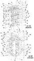
- Figs. 1A and 1B represent preexisting designs for multi-core cold boxes.
- Fig 1A represents a typical layout of a prior art design for a cold box design incorporating two to five cores. The specific example shown in Fig. 1A incorporates five cores.
- the cold box 2 includes a housing 4 that may be of structural steel and is shown in phantom in the drawings.
- the housing 4 is generally rectangular and includes, for reference purposes, a front 6, back 8, two spaced sides 10 and 12, a top 14 and a bottom 16 that together constitute an enclosed structure.
- manifolds 32 on the front 20, back 22, top 24 and bottom 26 surfaces depend upon the particular cryogenic process being used and the particular design of the interior of the heat exchanger unit.
- the manifolds 32 provide a fluid path to the interior of the core at various interior locations of the core depending upon the particular design and purpose of the core.
- headers 34 The exact number of headers 34 depends upon the particular design and purpose of the cores. Individual feed lines 36 (only some of which are numbered), which are linear in shape, extend between each of the headers 34 and its respective manifold 32 on each of the individual heat exchangers to provide a connection for flow from the header 34 to the manifold 32.
- the headers 34 may be used to convey such liquids and gases to and from the heat exchanger units 18 as warm feed gas (natural gas + methane refrigerant recycle), feed gas going to high pressure LNG, warm high pressure N 2 refrigerant, boiloff gas being recirculated, cold low pressure N 2 refrigerant and cold low pressure methane refrigerant.
- the particular liquid or gas being conveyed by the headers depends upon the particular cryogenic process.
- the interior of the cold box housing 4 may be filled with an insulation material such as perlite (not shown).
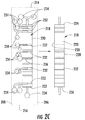
- the cores 118 are substantially rectangular in cross section, with a front surface 120, back surface 122, top surface 124, bottom surface 126 and two spaced side surfaces 128 and 130.
- the cores 118 are arranged in two rows with three cores 118 in each row in side-by-side relationship.
- the front surface 120, back surface 122, top surface 124 and bottom surface 126 of the cores 118 have manifolds 132 thereon that communicate with the interior of the core 118.
- the rows are positioned parallel to each other.
- the cores 118 are arranged such that the manifolds 132 extend generally parallel to the axis of each row of cores 118 and parallel to the front 106 and back 108 of the housing.
- the headers 234 may be used to convey such liquids and gases to and from the heat exchanger units 218 as warm feed gas (natural gas + methane refrigerant recycle), feed gas going to high pressure LNG, warm high pressure N 2 refrigerant, boiloff gas being recirculated, cold low pressure N 2 refrigerant and cold low pressure methane refrigerant.
- warm feed gas natural gas + methane refrigerant recycle
- feed gas going to high pressure LNG
- warm high pressure N 2 refrigerant warm high pressure N 2 refrigerant
- boiloff gas being recirculated
- cold low pressure N 2 refrigerant and cold low pressure methane refrigerant cold low pressure methane refrigerant.
- the particular liquid or gas being conveyed by the headers depends upon the particular cryogenic process.
- the free volume within the cold box may be filled with an insulation material such as perlite.
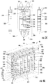
- Figs. 3A - 3C show a design according to the present disclosure that can be used for six or more cores 318. These Figures show specifically six cores 318 mounted in the cold box 44.
- the cold box 44 includes a housing 304 that may be of structural steel and is shown in phantom in the drawings.
- the housing 304 is generally rectangular and includes for reference purposes a front 306, back 308, two spaced sides 310 and 312, a top 314 and a bottom 316 that together constitute an enclosed structure.
- the cores 318 may be individual heat exchanger units, such as brazed aluminum plate fin heat exchangers.
- the cores 318 in Figs. 3A -C are substantially rectangular in cross section, and include, for reference purposes, a front surface 320, back surface 322, top surface 324, bottom surface 326, a side surface 328 and a side surface 330.
- the six cores 318 are arranged in two parallel rows with three cores 318 in each row.
- the cores 318 in each row are in a front-to-back relationship. Each of the two rows extends along an axis extending from side to side in the housing 302.
- the cores 318 are mounted in the housing 302 with their front and back surfaces 320 and 322 facing the sides 310 and 312 respectively of the housing 304 and their side surfaces 328 and 330 facing the front 306 and back 308 of the housing 304 respectively.
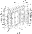
- some of the feed lines 336 have a configuration that includes a first section 351 that is connected to a manifold 332 and extends in an X direction parallel to the axis of the row of cores 318, a second intermediate section 352 that is fluidly connected to the first section and extends horizontally in a Z direction generally perpendicular to the axis of the row of cores 318, and a third section 353 that is fluidly connected to the second section and extends vertically in a Y direction perpendicular to the axis of the header 334 to which it is connected.
- a first section 351 that is connected to a manifold 332 and extends in an X direction parallel to the axis of the row of cores 318
- a second intermediate section 352 that is fluidly connected to the first section and extends horizontally in a Z direction generally perpendicular to the axis of the row of cores 318
- a third section 353 that is fluidly connected to the second section and extends vertically
- Headers 434 are provided that extend parallel to the axis of the row of cores 418 with each extending in a plane parallel to the front 406 and back 408 of the housing 404.
- the headers 434 extend perpendicular to the manifolds 432.
- the headers 434 extend through the side walls 410, 412 of the cold box housing 404 and are adapted to be connected to conduits (not shown) provided on the outside of the cold box housing 404.
- the headers 434 may be provided with companion flanges 435 at their open ends for connection to a similar flange provided on a conduit outside of the cold box.
- headers 434 there are fifteen headers 434 extending in the space between the two rows of cores 418 while each row has two headers 434 extending along the row above the cores 418 and one header 418 extending along the row below the cores.
- Individual feed lines 436 extend between each of the headers 434 and its respective manifold 432 on each of the cores 418 in a row to provide a connection for flow from the header 434 to the manifold 432.
- the feed lines may have configurations similar to those described in connection with Figs. 3A-3C .
- the free volume within the cold box may be filled with an insulating material such as perlite.
- the heat exchange units comprising the cold boxes described herein are typically configured to operate in the pressure range of 8963 kPa (1300 psig) or more, usually about 8693 to about 9653 kPa (1300 to about 1400 psig).
- the units typically have a minimum design operating temperature of -195 °C (-320 °F) or less, or -184 °C (-300 °F).
- the new cold boxes described herein have a variety of uses, and, as mentioned above, are particularly well-suited for inclusion in natural gas heat exchanger units, including LNG and FLNG units.
- the units can be maintained efficiently due to the ease of removal and replacement of cores needing repair.
- the size and/or weight of the cold box is increased as compared to the size and/or weight of a conventional system having generally the same capacity.
- the space between the cores will increase by about 10 - 50 %, or about 25 - 50 % as compared to a conventional system having the same capacity, resulting in certain circumstances in an overall increase in volume of the cold box of about 10 - 30 %, or about 20 - 30 %.
- the configuration within the cold box will employ additional pipe fittings that may increase the weight of the cold box by about 5 - 20 %, or about 10 - 20 % as compared to a conventional cold box having the same capacity.
Claims (15)
- Boîte froide (42) incluant :a. au moins un ensemble d'une pluralité de noyaux (218) à l'intérieur d'un caisson (204), chaque noyau (218) ayant un avant (220), un arrière (222), un dessus (224), un dessous (226) et une surface latérale (228, 230), les noyaux (218) dans chaque ensemble étant positionnés dans une rangée en relation d'avant en arrière le long d'un axe,b. le caisson (204) fournit une structure fermée,c. une pluralité de collecteurs (234) à l'intérieur du caisson (204) est adaptée à être raccordée à des conduites à l'extérieur du caisson (204), les collecteurs (234) s'étendant parallèlement à l'axe de la rangée de noyaux (218),d. des lignes d'alimentation (236) relient chacun des collecteurs (234) à un noyau (218) respectif,caractérisée en ce que :les noyaux ont une pluralité de raccords sur leurs surfaces avant et arrière, etles collecteurs sont positionnés sur le dessus, le dessous et/ou l'arrière des noyaux, avec l'espace entre un côté de tous les noyaux et le caisson étant dépourvu de collecteurs.
- Boîte froide (42) selon la revendication 1, dans laquelle les noyaux (218) comportent des unités d'échangeur de chaleur.
- Boîte froide (42) selon la revendication 1, dans laquelle la pluralité de noyaux (218) est agencée dans deux rangées.
- Boîte froide (42) selon la revendication 3, dans laquelle la pluralité de collecteurs (234) est positionnée sur le dessus, le dessous et entre les rangées de noyaux (218), l'espace entre un côté (228, 230) de chacun des noyaux (218) et le caisson (204) étant dépourvu de collecteurs (234).
- Boîte froide (42) selon la revendication 1, dans laquelle chaque collecteur de la pluralité de collecteurs (234) a un couplage d'accompagnement (235) sur son extrémité ouverte.
- Boîte froide (42) selon la revendication 2, dans laquelle les noyaux (218) comportent des échangeurs de chaleur en aluminium brasé.
- Boîte froide (42) selon la revendication 1, dans laquelle il y a un ensemble de noyaux (218) formant une seule rangée, la rangée ayant jusqu'à cinq noyaux (218).
- Boîte froide (42) selon la revendication 2, dans laquelle les raccords (232) s'étendent perpendiculairement à l'axe de la rangée dans laquelle les unités d'échangeur de chaleur sont positionnées.
- Boîte froide (42) selon la revendication 1, dans laquelle les collecteurs (234) sont positionnés sur le dessus, le dessous et l'arrière des noyaux (218).
- Boîte froide selon la revendication 1, dans laquelle un côté de chacun des noyaux est dirigé vers l'avant du caisson et l'autre côté est dirigé vers l'arrière du caisson.
- Boîte froide selon la revendication 1, dans laquelle l'axe de la rangée s'étend d'un côté à l'autre dans le caisson.
- Boîte froide selon la revendication 9, dans laquelle les collecteurs (234) s'étendent perpendiculairement aux raccords (232).
- Boîte froide (42) selon la revendication 1, dans laquelle la boîte froide (42) est disposée sur une unité de production de gaz naturel liquéfié flottant.
- Procédé de fabrication d'une boîte froide (42), comportant les étapes consistant à :obtenir un caisson (204) fournissant une structure fermée avec une paroi latérale amovible,disposer au moins un ensemble d'une pluralité de noyaux (218) à l'intérieur du caisson (204), chaque noyau (218) ayant un avant (220), un arrière (222), un dessus (224), un dessous (226) et une surface latérale (228, 230), les noyaux (218) dans chaque ensemble étant positionnés dans une rangée en relation d'avant en arrière le long d'un axe,disposer une pluralité de collecteurs (234) à l'intérieur du caisson (204), les collecteurs (234) étant configurés pour être raccordés à des conduites à l'extérieur du caisson (204), les collecteurs (234) s'étendant parallèlement à l'axe de la rangée de noyaux (218), etraccorder chacun des collecteurs (234) à un noyau (218) respectif en utilisant une ligne d'alimentation,caractérisé en ce que :les noyaux ont une pluralité de raccords sur leurs surfaces avant et arrière, etles collecteurs sont positionnés sur le dessus, le dessous et/ou l'arrière des noyaux, l'espace entre un côté de tous les noyaux et le caisson étant exempt des collecteurs.
- Procédé selon la revendication 14, dans lequel chacun des raccords (232) s'étend perpendiculairement à l'axe de la rangée dans laquelle les noyaux (218) sont positionnés.
Applications Claiming Priority (2)
| Application Number | Priority Date | Filing Date | Title |
|---|---|---|---|
| US13/453,597 US20130277021A1 (en) | 2012-04-23 | 2012-04-23 | Cold Box Design for Core Replacement |
| PCT/US2013/035780 WO2013162877A2 (fr) | 2012-04-23 | 2013-04-09 | Conception de boîte froide pour remplacement de cœur |
Publications (2)
| Publication Number | Publication Date |
|---|---|
| EP2861923A2 EP2861923A2 (fr) | 2015-04-22 |
| EP2861923B1 true EP2861923B1 (fr) | 2017-03-22 |
Family
ID=48143646
Family Applications (1)
| Application Number | Title | Priority Date | Filing Date |
|---|---|---|---|
| EP13718018.8A Revoked EP2861923B1 (fr) | 2012-04-23 | 2013-04-09 | Conception de boîte froide pour remplacement de coeligur |
Country Status (6)
| Country | Link |
|---|---|
| US (1) | US20130277021A1 (fr) |
| EP (1) | EP2861923B1 (fr) |
| JP (1) | JP6140811B2 (fr) |
| KR (1) | KR20150021919A (fr) |
| CA (1) | CA2871631A1 (fr) |
| WO (1) | WO2013162877A2 (fr) |
Families Citing this family (7)
| Publication number | Priority date | Publication date | Assignee | Title |
|---|---|---|---|---|
| NO337356B1 (no) * | 2014-04-22 | 2016-03-21 | Aker Engineering & Tech As | Prosesseringsanlegg |
| WO2016057443A1 (fr) * | 2014-10-07 | 2016-04-14 | Unison Industries, Llc | Échangeur de chaleur à courant se ramifiant dans plusieurs branches |
| US11892245B2 (en) | 2014-10-07 | 2024-02-06 | General Electric Company | Heat exchanger including furcating unit cells |
| FR3066265B1 (fr) * | 2017-05-11 | 2021-01-01 | Air Liquide | Appareil d'echange de chaleur |
| FR3101141B1 (fr) * | 2019-09-24 | 2023-04-14 | Air Liquide | Echangeur de chaleur, système de liquéfaction à double cycle de refrigération comportant ledit echangeur de chaleur |
| FR3120430B1 (fr) * | 2021-03-04 | 2024-01-05 | Arianegroup Sas | Dispositif de liquéfaction de gaz et procédé d’assemblage d’un tel dispositif |
| FR3120428B1 (fr) * | 2021-03-04 | 2024-01-05 | Arianegroup Sas | Procédé de maintenance d’un dispositif de liquéfaction de gaz |
Citations (5)
| Publication number | Priority date | Publication date | Assignee | Title |
|---|---|---|---|---|
| US4524728A (en) | 1983-07-25 | 1985-06-25 | Electric Power Research Institute, Inc. | Steam condensing apparatus |
| JPH1147279A (ja) | 1997-07-29 | 1999-02-23 | Tomoaki Otsuka | 生体バランスの改善と活性化方法 |
| US6250244B1 (en) | 1995-10-05 | 2001-06-26 | Bhp Petroleum Pty Ltd | Liquefaction apparatus |
| US6349566B1 (en) | 2000-09-15 | 2002-02-26 | Air Products And Chemicals, Inc. | Dephlegmator system and process |
| WO2006069983A1 (fr) | 2004-12-30 | 2006-07-06 | L'air Liquide, Societe Anonyme Pour L'etude Et L'exploitation Des Procedes Georges Claude | Ensemble d'echangeurs thermiques et appareil de distillation cryogenique ainsi equipe |
Family Cites Families (13)
| Publication number | Priority date | Publication date | Assignee | Title |
|---|---|---|---|---|
| JPS4947086Y1 (fr) * | 1969-05-09 | 1974-12-24 | ||
| JPH0789008B2 (ja) * | 1987-12-04 | 1995-09-27 | 日本酸素株式会社 | 凝縮蒸発器 |
| US4962810A (en) * | 1989-09-18 | 1990-10-16 | Rockwell International Corporation | Heat exchanger |
| JPH07243760A (ja) * | 1994-03-07 | 1995-09-19 | Kobe Steel Ltd | 熱交換装置 |
| US5755114A (en) | 1997-01-06 | 1998-05-26 | Abb Randall Corporation | Use of a turboexpander cycle in liquefied natural gas process |
| US6092591A (en) * | 1999-10-08 | 2000-07-25 | Abb Alstom Power Inc. | Top mounting arrangement for a heat exchange module |
| US6412302B1 (en) | 2001-03-06 | 2002-07-02 | Abb Lummus Global, Inc. - Randall Division | LNG production using dual independent expander refrigeration cycles |
| JP3565276B2 (ja) * | 2002-05-14 | 2004-09-15 | 木村工機株式会社 | ヒートポンプ式空調機 |
| US6889522B2 (en) | 2002-06-06 | 2005-05-10 | Abb Lummus Global, Randall Gas Technologies | LNG floating production, storage, and offloading scheme |
| JP5605977B2 (ja) * | 2004-06-23 | 2014-10-15 | エクソンモービル アップストリーム リサーチ カンパニー | 混合冷媒液化方法 |
| US7779899B2 (en) * | 2006-06-19 | 2010-08-24 | Praxair Technology, Inc. | Plate-fin heat exchanger having application to air separation |
| US20110139417A1 (en) * | 2009-12-16 | 2011-06-16 | Uop Llc | Method for making brazed aluminum heat exchanger and apparatus |
| JP5660845B2 (ja) * | 2010-10-13 | 2015-01-28 | 三菱重工業株式会社 | 液化方法、液化装置およびこれを備える浮体式液化ガス製造設備 |
-
2012
- 2012-04-23 US US13/453,597 patent/US20130277021A1/en not_active Abandoned
-
2013
- 2013-04-09 CA CA2871631A patent/CA2871631A1/fr not_active Abandoned
- 2013-04-09 WO PCT/US2013/035780 patent/WO2013162877A2/fr active Application Filing
- 2013-04-09 KR KR20147032685A patent/KR20150021919A/ko not_active Application Discontinuation
- 2013-04-09 JP JP2015509001A patent/JP6140811B2/ja not_active Expired - Fee Related
- 2013-04-09 EP EP13718018.8A patent/EP2861923B1/fr not_active Revoked
Patent Citations (5)
| Publication number | Priority date | Publication date | Assignee | Title |
|---|---|---|---|---|
| US4524728A (en) | 1983-07-25 | 1985-06-25 | Electric Power Research Institute, Inc. | Steam condensing apparatus |
| US6250244B1 (en) | 1995-10-05 | 2001-06-26 | Bhp Petroleum Pty Ltd | Liquefaction apparatus |
| JPH1147279A (ja) | 1997-07-29 | 1999-02-23 | Tomoaki Otsuka | 生体バランスの改善と活性化方法 |
| US6349566B1 (en) | 2000-09-15 | 2002-02-26 | Air Products And Chemicals, Inc. | Dephlegmator system and process |
| WO2006069983A1 (fr) | 2004-12-30 | 2006-07-06 | L'air Liquide, Societe Anonyme Pour L'etude Et L'exploitation Des Procedes Georges Claude | Ensemble d'echangeurs thermiques et appareil de distillation cryogenique ainsi equipe |
Also Published As
| Publication number | Publication date |
|---|---|
| JP2015522782A (ja) | 2015-08-06 |
| WO2013162877A2 (fr) | 2013-10-31 |
| US20130277021A1 (en) | 2013-10-24 |
| EP2861923A2 (fr) | 2015-04-22 |
| WO2013162877A3 (fr) | 2015-04-02 |
| KR20150021919A (ko) | 2015-03-03 |
| JP6140811B2 (ja) | 2017-05-31 |
| CA2871631A1 (fr) | 2013-10-31 |
Similar Documents
| Publication | Publication Date | Title |
|---|---|---|
| EP2861923B1 (fr) | Conception de boîte froide pour remplacement de coeligur | |
| US10060670B2 (en) | Air-cooled modular LNG production facility | |
| US9180938B2 (en) | Liquefied gas storage tank and marine structure including the same | |
| US6994104B2 (en) | Modular system for storing gas cylinders | |
| CA2419956C (fr) | Procedes et appareil permettant de transporter un gaz comprime | |
| US9360160B2 (en) | Liquefied natural gas storage container and method for manufacturing the same | |
| JP2020514665A (ja) | コンテナ化されたlng液化ユニット及び関連するlngを生産する方法 | |
| KR101419824B1 (ko) | 액화천연가스의 저장용기 | |
| WO2020129148A1 (fr) | Installation flottante | |
| US20100319877A1 (en) | Removable Flow Diversion Baffles for Liquefied Natural Gas Heat Exchangers | |
| KR102120558B1 (ko) | 액화가스 저장탱크의 단열시스템 및 이를 구비한 선박 | |
| KR200462375Y1 (ko) | 독립형 저장탱크의 누출액 수집장치 | |
| EP3674644B1 (fr) | Ensemble échangeur de chaleur et son procédé d'assemblage | |
| KR101210915B1 (ko) | 2열 배치 구조를 가지는 멤브레인형 lng 저장탱크 | |
| US11592234B2 (en) | Hydrocarbon fluid liquefaction system installation and system therefor | |
| CN202382519U (zh) | 深冷分离装置冷箱 | |
| Miller et al. | Application, Design and Operation Considerations for Brazed Aluminum Heat Exchangers in Liquefied Natural Gas Service | |
| KR101599294B1 (ko) | 저장탱크의 선적 및 하역장치, 그리고 상기 선적 및 하역장치를 가지는 부유식 구조물 | |
| KR101115465B1 (ko) | 액화천연가스의 생산 장치 | |
| WO2018150216A1 (fr) | Procédé et structure creuse servant à refroidir un fluide de transfert de chaleur |
Legal Events
| Date | Code | Title | Description |
|---|---|---|---|
| PUAI | Public reference made under article 153(3) epc to a published international application that has entered the european phase |
Free format text: ORIGINAL CODE: 0009012 |
|
| 17P | Request for examination filed |
Effective date: 20141121 |
|
| AK | Designated contracting states |
Kind code of ref document: A2 Designated state(s): AL AT BE BG CH CY CZ DE DK EE ES FI FR GB GR HR HU IE IS IT LI LT LU LV MC MK MT NL NO PL PT RO RS SE SI SK SM TR |
|
| AX | Request for extension of the european patent |
Extension state: BA ME |
|
| R17D | Deferred search report published (corrected) |
Effective date: 20150402 |
|
| R17P | Request for examination filed (corrected) |
Effective date: 20150427 |
|
| RBV | Designated contracting states (corrected) |
Designated state(s): AL AT BE BG CH CY CZ DE DK EE ES FI FR GB GR HR HU IE IS IT LI LT LU LV MC MK MT NL NO PL PT RO RS SE SI SK SM TR |
|
| DAX | Request for extension of the european patent (deleted) | ||
| GRAP | Despatch of communication of intention to grant a patent |
Free format text: ORIGINAL CODE: EPIDOSNIGR1 |
|
| INTG | Intention to grant announced |
Effective date: 20161010 |
|
| GRAS | Grant fee paid |
Free format text: ORIGINAL CODE: EPIDOSNIGR3 |
|
| STAA | Information on the status of an ep patent application or granted ep patent |
Free format text: STATUS: GRANT OF PATENT IS INTENDED |
|
| GRAA | (expected) grant |
Free format text: ORIGINAL CODE: 0009210 |
|
| STAA | Information on the status of an ep patent application or granted ep patent |
Free format text: STATUS: THE PATENT HAS BEEN GRANTED |
|
| AK | Designated contracting states |
Kind code of ref document: B1 Designated state(s): AL AT BE BG CH CY CZ DE DK EE ES FI FR GB GR HR HU IE IS IT LI LT LU LV MC MK MT NL NO PL PT RO RS SE SI SK SM TR |
|
| REG | Reference to a national code |
Ref country code: GB Ref legal event code: FG4D |
|
| REG | Reference to a national code |
Ref country code: CH Ref legal event code: EP |
|
| REG | Reference to a national code |
Ref country code: AT Ref legal event code: REF Ref document number: 878200 Country of ref document: AT Kind code of ref document: T Effective date: 20170415 |
|
| REG | Reference to a national code |
Ref country code: IE Ref legal event code: FG4D |
|
| REG | Reference to a national code |
Ref country code: DE Ref legal event code: R096 Ref document number: 602013018871 Country of ref document: DE |
|
| REG | Reference to a national code |
Ref country code: NL Ref legal event code: MP Effective date: 20170322 |
|
| PG25 | Lapsed in a contracting state [announced via postgrant information from national office to epo] |
Ref country code: NO Free format text: LAPSE BECAUSE OF FAILURE TO SUBMIT A TRANSLATION OF THE DESCRIPTION OR TO PAY THE FEE WITHIN THE PRESCRIBED TIME-LIMIT Effective date: 20170622 Ref country code: FI Free format text: LAPSE BECAUSE OF FAILURE TO SUBMIT A TRANSLATION OF THE DESCRIPTION OR TO PAY THE FEE WITHIN THE PRESCRIBED TIME-LIMIT Effective date: 20170322 Ref country code: HR Free format text: LAPSE BECAUSE OF FAILURE TO SUBMIT A TRANSLATION OF THE DESCRIPTION OR TO PAY THE FEE WITHIN THE PRESCRIBED TIME-LIMIT Effective date: 20170322 Ref country code: LT Free format text: LAPSE BECAUSE OF FAILURE TO SUBMIT A TRANSLATION OF THE DESCRIPTION OR TO PAY THE FEE WITHIN THE PRESCRIBED TIME-LIMIT Effective date: 20170322 Ref country code: GR Free format text: LAPSE BECAUSE OF FAILURE TO SUBMIT A TRANSLATION OF THE DESCRIPTION OR TO PAY THE FEE WITHIN THE PRESCRIBED TIME-LIMIT Effective date: 20170623 |
|
| REG | Reference to a national code |
Ref country code: LT Ref legal event code: MG4D |
|
| REG | Reference to a national code |
Ref country code: AT Ref legal event code: MK05 Ref document number: 878200 Country of ref document: AT Kind code of ref document: T Effective date: 20170322 |
|
| PG25 | Lapsed in a contracting state [announced via postgrant information from national office to epo] |
Ref country code: LV Free format text: LAPSE BECAUSE OF FAILURE TO SUBMIT A TRANSLATION OF THE DESCRIPTION OR TO PAY THE FEE WITHIN THE PRESCRIBED TIME-LIMIT Effective date: 20170322 Ref country code: RS Free format text: LAPSE BECAUSE OF FAILURE TO SUBMIT A TRANSLATION OF THE DESCRIPTION OR TO PAY THE FEE WITHIN THE PRESCRIBED TIME-LIMIT Effective date: 20170322 Ref country code: SE Free format text: LAPSE BECAUSE OF FAILURE TO SUBMIT A TRANSLATION OF THE DESCRIPTION OR TO PAY THE FEE WITHIN THE PRESCRIBED TIME-LIMIT Effective date: 20170322 Ref country code: BG Free format text: LAPSE BECAUSE OF FAILURE TO SUBMIT A TRANSLATION OF THE DESCRIPTION OR TO PAY THE FEE WITHIN THE PRESCRIBED TIME-LIMIT Effective date: 20170622 |
|
| PG25 | Lapsed in a contracting state [announced via postgrant information from national office to epo] |
Ref country code: NL Free format text: LAPSE BECAUSE OF FAILURE TO SUBMIT A TRANSLATION OF THE DESCRIPTION OR TO PAY THE FEE WITHIN THE PRESCRIBED TIME-LIMIT Effective date: 20170322 |
|
| PG25 | Lapsed in a contracting state [announced via postgrant information from national office to epo] |
Ref country code: RO Free format text: LAPSE BECAUSE OF FAILURE TO SUBMIT A TRANSLATION OF THE DESCRIPTION OR TO PAY THE FEE WITHIN THE PRESCRIBED TIME-LIMIT Effective date: 20170322 Ref country code: AT Free format text: LAPSE BECAUSE OF FAILURE TO SUBMIT A TRANSLATION OF THE DESCRIPTION OR TO PAY THE FEE WITHIN THE PRESCRIBED TIME-LIMIT Effective date: 20170322 Ref country code: IT Free format text: LAPSE BECAUSE OF FAILURE TO SUBMIT A TRANSLATION OF THE DESCRIPTION OR TO PAY THE FEE WITHIN THE PRESCRIBED TIME-LIMIT Effective date: 20170322 Ref country code: ES Free format text: LAPSE BECAUSE OF FAILURE TO SUBMIT A TRANSLATION OF THE DESCRIPTION OR TO PAY THE FEE WITHIN THE PRESCRIBED TIME-LIMIT Effective date: 20170322 Ref country code: EE Free format text: LAPSE BECAUSE OF FAILURE TO SUBMIT A TRANSLATION OF THE DESCRIPTION OR TO PAY THE FEE WITHIN THE PRESCRIBED TIME-LIMIT Effective date: 20170322 Ref country code: CZ Free format text: LAPSE BECAUSE OF FAILURE TO SUBMIT A TRANSLATION OF THE DESCRIPTION OR TO PAY THE FEE WITHIN THE PRESCRIBED TIME-LIMIT Effective date: 20170322 Ref country code: SK Free format text: LAPSE BECAUSE OF FAILURE TO SUBMIT A TRANSLATION OF THE DESCRIPTION OR TO PAY THE FEE WITHIN THE PRESCRIBED TIME-LIMIT Effective date: 20170322 |
|
| REG | Reference to a national code |
Ref country code: DE Ref legal event code: R119 Ref document number: 602013018871 Country of ref document: DE |
|
| PG25 | Lapsed in a contracting state [announced via postgrant information from national office to epo] |
Ref country code: IS Free format text: LAPSE BECAUSE OF FAILURE TO SUBMIT A TRANSLATION OF THE DESCRIPTION OR TO PAY THE FEE WITHIN THE PRESCRIBED TIME-LIMIT Effective date: 20170722 Ref country code: PT Free format text: LAPSE BECAUSE OF FAILURE TO SUBMIT A TRANSLATION OF THE DESCRIPTION OR TO PAY THE FEE WITHIN THE PRESCRIBED TIME-LIMIT Effective date: 20170724 Ref country code: PL Free format text: LAPSE BECAUSE OF FAILURE TO SUBMIT A TRANSLATION OF THE DESCRIPTION OR TO PAY THE FEE WITHIN THE PRESCRIBED TIME-LIMIT Effective date: 20170322 Ref country code: SM Free format text: LAPSE BECAUSE OF FAILURE TO SUBMIT A TRANSLATION OF THE DESCRIPTION OR TO PAY THE FEE WITHIN THE PRESCRIBED TIME-LIMIT Effective date: 20170322 |
|
| REG | Reference to a national code |
Ref country code: CH Ref legal event code: PL |
|
| PLBI | Opposition filed |
Free format text: ORIGINAL CODE: 0009260 |
|
| PLAX | Notice of opposition and request to file observation + time limit sent |
Free format text: ORIGINAL CODE: EPIDOSNOBS2 |
|
| 26 | Opposition filed |
Opponent name: L'AIR LIQUIDE, SOCIETE ANONYME POUR L'ETUDE ET L'E Effective date: 20171221 |
|
| REG | Reference to a national code |
Ref country code: IE Ref legal event code: MM4A |
|
| REG | Reference to a national code |
Ref country code: FR Ref legal event code: ST Effective date: 20171229 |
|
| PG25 | Lapsed in a contracting state [announced via postgrant information from national office to epo] |
Ref country code: FR Free format text: LAPSE BECAUSE OF NON-PAYMENT OF DUE FEES Effective date: 20170522 Ref country code: DE Free format text: LAPSE BECAUSE OF NON-PAYMENT OF DUE FEES Effective date: 20171103 Ref country code: MC Free format text: LAPSE BECAUSE OF FAILURE TO SUBMIT A TRANSLATION OF THE DESCRIPTION OR TO PAY THE FEE WITHIN THE PRESCRIBED TIME-LIMIT Effective date: 20170322 Ref country code: DK Free format text: LAPSE BECAUSE OF FAILURE TO SUBMIT A TRANSLATION OF THE DESCRIPTION OR TO PAY THE FEE WITHIN THE PRESCRIBED TIME-LIMIT Effective date: 20170322 |
|
| GBPC | Gb: european patent ceased through non-payment of renewal fee |
Effective date: 20170622 |
|
| PG25 | Lapsed in a contracting state [announced via postgrant information from national office to epo] |
Ref country code: CH Free format text: LAPSE BECAUSE OF NON-PAYMENT OF DUE FEES Effective date: 20170430 Ref country code: LI Free format text: LAPSE BECAUSE OF NON-PAYMENT OF DUE FEES Effective date: 20170430 Ref country code: SI Free format text: LAPSE BECAUSE OF FAILURE TO SUBMIT A TRANSLATION OF THE DESCRIPTION OR TO PAY THE FEE WITHIN THE PRESCRIBED TIME-LIMIT Effective date: 20170322 Ref country code: LU Free format text: LAPSE BECAUSE OF NON-PAYMENT OF DUE FEES Effective date: 20170409 |
|
| REG | Reference to a national code |
Ref country code: BE Ref legal event code: MM Effective date: 20170430 |
|
| PG25 | Lapsed in a contracting state [announced via postgrant information from national office to epo] |
Ref country code: GB Free format text: LAPSE BECAUSE OF NON-PAYMENT OF DUE FEES Effective date: 20170622 Ref country code: IE Free format text: LAPSE BECAUSE OF NON-PAYMENT OF DUE FEES Effective date: 20170409 |
|
| PG25 | Lapsed in a contracting state [announced via postgrant information from national office to epo] |
Ref country code: BE Free format text: LAPSE BECAUSE OF NON-PAYMENT OF DUE FEES Effective date: 20170430 |
|
| RDAF | Communication despatched that patent is revoked |
Free format text: ORIGINAL CODE: EPIDOSNREV1 |
|
| PG25 | Lapsed in a contracting state [announced via postgrant information from national office to epo] |
Ref country code: MT Free format text: LAPSE BECAUSE OF NON-PAYMENT OF DUE FEES Effective date: 20170409 |
|
| RDAG | Patent revoked |
Free format text: ORIGINAL CODE: 0009271 |
|
| STAA | Information on the status of an ep patent application or granted ep patent |
Free format text: STATUS: PATENT REVOKED |
|
| 27W | Patent revoked |
Effective date: 20180924 |
|
| PG25 | Lapsed in a contracting state [announced via postgrant information from national office to epo] |
Ref country code: MK Free format text: LAPSE BECAUSE OF FAILURE TO SUBMIT A TRANSLATION OF THE DESCRIPTION OR TO PAY THE FEE WITHIN THE PRESCRIBED TIME-LIMIT Effective date: 20170322 |
|
| PG25 | Lapsed in a contracting state [announced via postgrant information from national office to epo] |
Ref country code: CY Free format text: LAPSE BECAUSE OF FAILURE TO SUBMIT A TRANSLATION OF THE DESCRIPTION OR TO PAY THE FEE WITHIN THE PRESCRIBED TIME-LIMIT Effective date: 20170322 |
|
| PG25 | Lapsed in a contracting state [announced via postgrant information from national office to epo] |
Ref country code: AL Free format text: LAPSE BECAUSE OF FAILURE TO SUBMIT A TRANSLATION OF THE DESCRIPTION OR TO PAY THE FEE WITHIN THE PRESCRIBED TIME-LIMIT Effective date: 20170322 |
|
| PG25 | Lapsed in a contracting state [announced via postgrant information from national office to epo] |
Ref country code: TR Free format text: LAPSE BECAUSE OF FAILURE TO SUBMIT A TRANSLATION OF THE DESCRIPTION OR TO PAY THE FEE WITHIN THE PRESCRIBED TIME-LIMIT Effective date: 20170322 |