EP2861923B1 - Cold box design for core replacement - Google Patents
Cold box design for core replacement Download PDFInfo
- Publication number
- EP2861923B1 EP2861923B1 EP13718018.8A EP13718018A EP2861923B1 EP 2861923 B1 EP2861923 B1 EP 2861923B1 EP 13718018 A EP13718018 A EP 13718018A EP 2861923 B1 EP2861923 B1 EP 2861923B1
- Authority
- EP
- European Patent Office
- Prior art keywords
- cores
- headers
- housing
- cold box
- row
- Prior art date
- Legal status (The legal status is an assumption and is not a legal conclusion. Google has not performed a legal analysis and makes no representation as to the accuracy of the status listed.)
- Revoked
Links
- 238000013461 design Methods 0.000 title description 39
- 239000003949 liquefied natural gas Substances 0.000 claims description 11
- 238000000034 method Methods 0.000 claims description 10
- XAGFODPZIPBFFR-UHFFFAOYSA-N aluminium Chemical compound [Al] XAGFODPZIPBFFR-UHFFFAOYSA-N 0.000 claims description 7
- 229910052782 aluminium Inorganic materials 0.000 claims description 7
- 238000004519 manufacturing process Methods 0.000 claims description 6
- 230000008878 coupling Effects 0.000 claims 1
- 238000010168 coupling process Methods 0.000 claims 1
- 238000005859 coupling reaction Methods 0.000 claims 1
- VNWKTOKETHGBQD-UHFFFAOYSA-N methane Chemical compound C VNWKTOKETHGBQD-UHFFFAOYSA-N 0.000 description 22
- 230000008439 repair process Effects 0.000 description 19
- 239000007789 gas Substances 0.000 description 13
- 239000012530 fluid Substances 0.000 description 8
- 239000003507 refrigerant Substances 0.000 description 8
- 239000003345 natural gas Substances 0.000 description 7
- 229910000746 Structural steel Inorganic materials 0.000 description 6
- 235000019362 perlite Nutrition 0.000 description 6
- 239000010451 perlite Substances 0.000 description 6
- 238000012423 maintenance Methods 0.000 description 5
- 239000012774 insulation material Substances 0.000 description 4
- 239000007788 liquid Substances 0.000 description 4
- 230000000903 blocking effect Effects 0.000 description 3
- 238000005516 engineering process Methods 0.000 description 3
- 239000003915 liquefied petroleum gas Substances 0.000 description 3
- 238000012545 processing Methods 0.000 description 2
- 238000003860 storage Methods 0.000 description 2
- 239000004215 Carbon black (E152) Substances 0.000 description 1
- 238000005219 brazing Methods 0.000 description 1
- 230000001419 dependent effect Effects 0.000 description 1
- 238000011161 development Methods 0.000 description 1
- 230000018109 developmental process Effects 0.000 description 1
- 229930195733 hydrocarbon Natural products 0.000 description 1
- 150000002430 hydrocarbons Chemical class 0.000 description 1
- 238000009434 installation Methods 0.000 description 1
- 239000011810 insulating material Substances 0.000 description 1
- 238000009413 insulation Methods 0.000 description 1
- 238000003032 molecular docking Methods 0.000 description 1
- 239000003209 petroleum derivative Substances 0.000 description 1
- 238000011160 research Methods 0.000 description 1
- 238000012546 transfer Methods 0.000 description 1
- 239000013585 weight reducing agent Substances 0.000 description 1
Images


Classifications
-
- F—MECHANICAL ENGINEERING; LIGHTING; HEATING; WEAPONS; BLASTING
- F28—HEAT EXCHANGE IN GENERAL
- F28D—HEAT-EXCHANGE APPARATUS, NOT PROVIDED FOR IN ANOTHER SUBCLASS, IN WHICH THE HEAT-EXCHANGE MEDIA DO NOT COME INTO DIRECT CONTACT
- F28D9/00—Heat-exchange apparatus having stationary plate-like or laminated conduit assemblies for both heat-exchange media, the media being in contact with different sides of a conduit wall
-
- F—MECHANICAL ENGINEERING; LIGHTING; HEATING; WEAPONS; BLASTING
- F25—REFRIGERATION OR COOLING; COMBINED HEATING AND REFRIGERATION SYSTEMS; HEAT PUMP SYSTEMS; MANUFACTURE OR STORAGE OF ICE; LIQUEFACTION SOLIDIFICATION OF GASES
- F25J—LIQUEFACTION, SOLIDIFICATION OR SEPARATION OF GASES OR GASEOUS OR LIQUEFIED GASEOUS MIXTURES BY PRESSURE AND COLD TREATMENT OR BY BRINGING THEM INTO THE SUPERCRITICAL STATE
- F25J1/00—Processes or apparatus for liquefying or solidifying gases or gaseous mixtures
- F25J1/0002—Processes or apparatus for liquefying or solidifying gases or gaseous mixtures characterised by the fluid to be liquefied
- F25J1/0022—Hydrocarbons, e.g. natural gas
-
- F—MECHANICAL ENGINEERING; LIGHTING; HEATING; WEAPONS; BLASTING
- F25—REFRIGERATION OR COOLING; COMBINED HEATING AND REFRIGERATION SYSTEMS; HEAT PUMP SYSTEMS; MANUFACTURE OR STORAGE OF ICE; LIQUEFACTION SOLIDIFICATION OF GASES
- F25J—LIQUEFACTION, SOLIDIFICATION OR SEPARATION OF GASES OR GASEOUS OR LIQUEFIED GASEOUS MIXTURES BY PRESSURE AND COLD TREATMENT OR BY BRINGING THEM INTO THE SUPERCRITICAL STATE
- F25J1/00—Processes or apparatus for liquefying or solidifying gases or gaseous mixtures
- F25J1/02—Processes or apparatus for liquefying or solidifying gases or gaseous mixtures requiring the use of refrigeration, e.g. of helium or hydrogen ; Details and kind of the refrigeration system used; Integration with other units or processes; Controlling aspects of the process
- F25J1/0243—Start-up or control of the process; Details of the apparatus used; Details of the refrigerant compression system used
- F25J1/0244—Operation; Control and regulation; Instrumentation
- F25J1/0245—Different modes, i.e. 'runs', of operation; Process control
- F25J1/0248—Stopping of the process, e.g. defrosting or deriming, maintenance; Back-up mode or systems
-
- F—MECHANICAL ENGINEERING; LIGHTING; HEATING; WEAPONS; BLASTING
- F25—REFRIGERATION OR COOLING; COMBINED HEATING AND REFRIGERATION SYSTEMS; HEAT PUMP SYSTEMS; MANUFACTURE OR STORAGE OF ICE; LIQUEFACTION SOLIDIFICATION OF GASES
- F25J—LIQUEFACTION, SOLIDIFICATION OR SEPARATION OF GASES OR GASEOUS OR LIQUEFIED GASEOUS MIXTURES BY PRESSURE AND COLD TREATMENT OR BY BRINGING THEM INTO THE SUPERCRITICAL STATE
- F25J1/00—Processes or apparatus for liquefying or solidifying gases or gaseous mixtures
- F25J1/02—Processes or apparatus for liquefying or solidifying gases or gaseous mixtures requiring the use of refrigeration, e.g. of helium or hydrogen ; Details and kind of the refrigeration system used; Integration with other units or processes; Controlling aspects of the process
- F25J1/0243—Start-up or control of the process; Details of the apparatus used; Details of the refrigerant compression system used
- F25J1/0257—Construction and layout of liquefaction equipments, e.g. valves, machines
- F25J1/0259—Modularity and arrangement of parts of the liquefaction unit and in particular of the cold box, e.g. pre-fabrication, assembling and erection, dimensions, horizontal layout "plot"
-
- F—MECHANICAL ENGINEERING; LIGHTING; HEATING; WEAPONS; BLASTING
- F25—REFRIGERATION OR COOLING; COMBINED HEATING AND REFRIGERATION SYSTEMS; HEAT PUMP SYSTEMS; MANUFACTURE OR STORAGE OF ICE; LIQUEFACTION SOLIDIFICATION OF GASES
- F25J—LIQUEFACTION, SOLIDIFICATION OR SEPARATION OF GASES OR GASEOUS OR LIQUEFIED GASEOUS MIXTURES BY PRESSURE AND COLD TREATMENT OR BY BRINGING THEM INTO THE SUPERCRITICAL STATE
- F25J1/00—Processes or apparatus for liquefying or solidifying gases or gaseous mixtures
- F25J1/02—Processes or apparatus for liquefying or solidifying gases or gaseous mixtures requiring the use of refrigeration, e.g. of helium or hydrogen ; Details and kind of the refrigeration system used; Integration with other units or processes; Controlling aspects of the process
- F25J1/0243—Start-up or control of the process; Details of the apparatus used; Details of the refrigerant compression system used
- F25J1/0257—Construction and layout of liquefaction equipments, e.g. valves, machines
- F25J1/0269—Arrangement of liquefaction units or equipments fulfilling the same process step, e.g. multiple "trains" concept
- F25J1/0271—Inter-connecting multiple cold equipments within or downstream of the cold box
- F25J1/0272—Multiple identical heat exchangers in parallel
-
- F—MECHANICAL ENGINEERING; LIGHTING; HEATING; WEAPONS; BLASTING
- F25—REFRIGERATION OR COOLING; COMBINED HEATING AND REFRIGERATION SYSTEMS; HEAT PUMP SYSTEMS; MANUFACTURE OR STORAGE OF ICE; LIQUEFACTION SOLIDIFICATION OF GASES
- F25J—LIQUEFACTION, SOLIDIFICATION OR SEPARATION OF GASES OR GASEOUS OR LIQUEFIED GASEOUS MIXTURES BY PRESSURE AND COLD TREATMENT OR BY BRINGING THEM INTO THE SUPERCRITICAL STATE
- F25J5/00—Arrangements of cold exchangers or cold accumulators in separation or liquefaction plants
- F25J5/002—Arrangements of cold exchangers or cold accumulators in separation or liquefaction plants for continuously recuperating cold, i.e. in a so-called recuperative heat exchanger
-
- F—MECHANICAL ENGINEERING; LIGHTING; HEATING; WEAPONS; BLASTING
- F28—HEAT EXCHANGE IN GENERAL
- F28F—DETAILS OF HEAT-EXCHANGE AND HEAT-TRANSFER APPARATUS, OF GENERAL APPLICATION
- F28F9/00—Casings; Header boxes; Auxiliary supports for elements; Auxiliary members within casings
- F28F9/02—Header boxes; End plates
- F28F9/0243—Header boxes having a circular cross-section
-
- F—MECHANICAL ENGINEERING; LIGHTING; HEATING; WEAPONS; BLASTING
- F28—HEAT EXCHANGE IN GENERAL
- F28F—DETAILS OF HEAT-EXCHANGE AND HEAT-TRANSFER APPARATUS, OF GENERAL APPLICATION
- F28F9/00—Casings; Header boxes; Auxiliary supports for elements; Auxiliary members within casings
- F28F9/02—Header boxes; End plates
- F28F9/026—Header boxes; End plates with static flow control means, e.g. with means for uniformly distributing heat exchange media into conduits
- F28F9/027—Header boxes; End plates with static flow control means, e.g. with means for uniformly distributing heat exchange media into conduits in the form of distribution pipes
- F28F9/0275—Header boxes; End plates with static flow control means, e.g. with means for uniformly distributing heat exchange media into conduits in the form of distribution pipes with multiple branch pipes
-
- F—MECHANICAL ENGINEERING; LIGHTING; HEATING; WEAPONS; BLASTING
- F25—REFRIGERATION OR COOLING; COMBINED HEATING AND REFRIGERATION SYSTEMS; HEAT PUMP SYSTEMS; MANUFACTURE OR STORAGE OF ICE; LIQUEFACTION SOLIDIFICATION OF GASES
- F25J—LIQUEFACTION, SOLIDIFICATION OR SEPARATION OF GASES OR GASEOUS OR LIQUEFIED GASEOUS MIXTURES BY PRESSURE AND COLD TREATMENT OR BY BRINGING THEM INTO THE SUPERCRITICAL STATE
- F25J2290/00—Other details not covered by groups F25J2200/00 - F25J2280/00
- F25J2290/42—Modularity, pre-fabrication of modules, assembling and erection, horizontal layout, i.e. plot plan, and vertical arrangement of parts of the cryogenic unit, e.g. of the cold box
-
- F—MECHANICAL ENGINEERING; LIGHTING; HEATING; WEAPONS; BLASTING
- F25—REFRIGERATION OR COOLING; COMBINED HEATING AND REFRIGERATION SYSTEMS; HEAT PUMP SYSTEMS; MANUFACTURE OR STORAGE OF ICE; LIQUEFACTION SOLIDIFICATION OF GASES
- F25J—LIQUEFACTION, SOLIDIFICATION OR SEPARATION OF GASES OR GASEOUS OR LIQUEFIED GASEOUS MIXTURES BY PRESSURE AND COLD TREATMENT OR BY BRINGING THEM INTO THE SUPERCRITICAL STATE
- F25J2290/00—Other details not covered by groups F25J2200/00 - F25J2280/00
- F25J2290/50—Arrangement of multiple equipments fulfilling the same process step in parallel
-
- Y—GENERAL TAGGING OF NEW TECHNOLOGICAL DEVELOPMENTS; GENERAL TAGGING OF CROSS-SECTIONAL TECHNOLOGIES SPANNING OVER SEVERAL SECTIONS OF THE IPC; TECHNICAL SUBJECTS COVERED BY FORMER USPC CROSS-REFERENCE ART COLLECTIONS [XRACs] AND DIGESTS
- Y10—TECHNICAL SUBJECTS COVERED BY FORMER USPC
- Y10T—TECHNICAL SUBJECTS COVERED BY FORMER US CLASSIFICATION
- Y10T29/00—Metal working
- Y10T29/49—Method of mechanical manufacture
- Y10T29/4935—Heat exchanger or boiler making
- Y10T29/49359—Cooling apparatus making, e.g., air conditioner, refrigerator
Definitions
- the maximum size of a heat exchanger that can be fabricated is limited by the size of the manufacturer's brazing furnace.
- multiple sections of heat exchanger units referred to as "cores,” are fabricated and interconnected to form the complete heat exchanger.
- cores are fabricated and interconnected to form the complete heat exchanger.
- a cold box configuration is utilized, with the exchanger assembled within a structural steel framework (the box), with an insulation such as perlite filling the voids within the box for heat conservation.
- maintenance can often be an issue, requiring extended shutdown periods to accomplish the necessary repairs required.
- the current practice of interconnecting the cores within the cold box impedes maintenance.
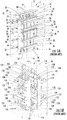
- Figs. 1A and 1B represent preexisting designs for multi-core cold boxes.
- Fig 1A represents a typical layout of a prior art design for a cold box design incorporating two to five cores. The specific example shown in Fig. 1A incorporates five cores.
- the cold box 2 includes a housing 4 that may be of structural steel and is shown in phantom in the drawings.
- the housing 4 is generally rectangular and includes, for reference purposes, a front 6, back 8, two spaced sides 10 and 12, a top 14 and a bottom 16 that together constitute an enclosed structure.
- manifolds 32 on the front 20, back 22, top 24 and bottom 26 surfaces depend upon the particular cryogenic process being used and the particular design of the interior of the heat exchanger unit.
- the manifolds 32 provide a fluid path to the interior of the core at various interior locations of the core depending upon the particular design and purpose of the core.
- headers 34 The exact number of headers 34 depends upon the particular design and purpose of the cores. Individual feed lines 36 (only some of which are numbered), which are linear in shape, extend between each of the headers 34 and its respective manifold 32 on each of the individual heat exchangers to provide a connection for flow from the header 34 to the manifold 32.
- the headers 34 may be used to convey such liquids and gases to and from the heat exchanger units 18 as warm feed gas (natural gas + methane refrigerant recycle), feed gas going to high pressure LNG, warm high pressure N 2 refrigerant, boiloff gas being recirculated, cold low pressure N 2 refrigerant and cold low pressure methane refrigerant.
- the particular liquid or gas being conveyed by the headers depends upon the particular cryogenic process.
- the interior of the cold box housing 4 may be filled with an insulation material such as perlite (not shown).
- the cores 118 are substantially rectangular in cross section, with a front surface 120, back surface 122, top surface 124, bottom surface 126 and two spaced side surfaces 128 and 130.
- the cores 118 are arranged in two rows with three cores 118 in each row in side-by-side relationship.
- the front surface 120, back surface 122, top surface 124 and bottom surface 126 of the cores 118 have manifolds 132 thereon that communicate with the interior of the core 118.
- the rows are positioned parallel to each other.
- the cores 118 are arranged such that the manifolds 132 extend generally parallel to the axis of each row of cores 118 and parallel to the front 106 and back 108 of the housing.
- the headers 234 may be used to convey such liquids and gases to and from the heat exchanger units 218 as warm feed gas (natural gas + methane refrigerant recycle), feed gas going to high pressure LNG, warm high pressure N 2 refrigerant, boiloff gas being recirculated, cold low pressure N 2 refrigerant and cold low pressure methane refrigerant.
- warm feed gas natural gas + methane refrigerant recycle
- feed gas going to high pressure LNG
- warm high pressure N 2 refrigerant warm high pressure N 2 refrigerant
- boiloff gas being recirculated
- cold low pressure N 2 refrigerant and cold low pressure methane refrigerant cold low pressure methane refrigerant.
- the particular liquid or gas being conveyed by the headers depends upon the particular cryogenic process.
- the free volume within the cold box may be filled with an insulation material such as perlite.
- Figs. 3A - 3C show a design according to the present disclosure that can be used for six or more cores 318. These Figures show specifically six cores 318 mounted in the cold box 44.
- the cold box 44 includes a housing 304 that may be of structural steel and is shown in phantom in the drawings.
- the housing 304 is generally rectangular and includes for reference purposes a front 306, back 308, two spaced sides 310 and 312, a top 314 and a bottom 316 that together constitute an enclosed structure.
- the cores 318 may be individual heat exchanger units, such as brazed aluminum plate fin heat exchangers.
- the cores 318 in Figs. 3A -C are substantially rectangular in cross section, and include, for reference purposes, a front surface 320, back surface 322, top surface 324, bottom surface 326, a side surface 328 and a side surface 330.
- the six cores 318 are arranged in two parallel rows with three cores 318 in each row.
- the cores 318 in each row are in a front-to-back relationship. Each of the two rows extends along an axis extending from side to side in the housing 302.
- the cores 318 are mounted in the housing 302 with their front and back surfaces 320 and 322 facing the sides 310 and 312 respectively of the housing 304 and their side surfaces 328 and 330 facing the front 306 and back 308 of the housing 304 respectively.
- some of the feed lines 336 have a configuration that includes a first section 351 that is connected to a manifold 332 and extends in an X direction parallel to the axis of the row of cores 318, a second intermediate section 352 that is fluidly connected to the first section and extends horizontally in a Z direction generally perpendicular to the axis of the row of cores 318, and a third section 353 that is fluidly connected to the second section and extends vertically in a Y direction perpendicular to the axis of the header 334 to which it is connected.
- a first section 351 that is connected to a manifold 332 and extends in an X direction parallel to the axis of the row of cores 318
- a second intermediate section 352 that is fluidly connected to the first section and extends horizontally in a Z direction generally perpendicular to the axis of the row of cores 318
- a third section 353 that is fluidly connected to the second section and extends vertically
- Headers 434 are provided that extend parallel to the axis of the row of cores 418 with each extending in a plane parallel to the front 406 and back 408 of the housing 404.
- the headers 434 extend perpendicular to the manifolds 432.
- the headers 434 extend through the side walls 410, 412 of the cold box housing 404 and are adapted to be connected to conduits (not shown) provided on the outside of the cold box housing 404.
- the headers 434 may be provided with companion flanges 435 at their open ends for connection to a similar flange provided on a conduit outside of the cold box.
- headers 434 there are fifteen headers 434 extending in the space between the two rows of cores 418 while each row has two headers 434 extending along the row above the cores 418 and one header 418 extending along the row below the cores.
- Individual feed lines 436 extend between each of the headers 434 and its respective manifold 432 on each of the cores 418 in a row to provide a connection for flow from the header 434 to the manifold 432.
- the feed lines may have configurations similar to those described in connection with Figs. 3A-3C .
- the free volume within the cold box may be filled with an insulating material such as perlite.
- the heat exchange units comprising the cold boxes described herein are typically configured to operate in the pressure range of 8963 kPa (1300 psig) or more, usually about 8693 to about 9653 kPa (1300 to about 1400 psig).
- the units typically have a minimum design operating temperature of -195 °C (-320 °F) or less, or -184 °C (-300 °F).
- the new cold boxes described herein have a variety of uses, and, as mentioned above, are particularly well-suited for inclusion in natural gas heat exchanger units, including LNG and FLNG units.
- the units can be maintained efficiently due to the ease of removal and replacement of cores needing repair.
- the size and/or weight of the cold box is increased as compared to the size and/or weight of a conventional system having generally the same capacity.
- the space between the cores will increase by about 10 - 50 %, or about 25 - 50 % as compared to a conventional system having the same capacity, resulting in certain circumstances in an overall increase in volume of the cold box of about 10 - 30 %, or about 20 - 30 %.
- the configuration within the cold box will employ additional pipe fittings that may increase the weight of the cold box by about 5 - 20 %, or about 10 - 20 % as compared to a conventional cold box having the same capacity.
Description
- This application relates generally to a design for a cold box, and more particularly, to a cold box having a design that enhances core replacement.
- Hydrocarbon gases such as natural gas are liquefied by cryogenic processes to reduce their volume for easier transportation and storage. Brazed aluminum plate fin heat exchangers have been utilized in the cryogenic processing of natural gas and liquefied natural gas (LNG) for many years. Compared to conventional shell & tube exchangers, they offer many advantages, including smaller size and weight, and hence less cost.
- The maximum size of a heat exchanger that can be fabricated is limited by the size of the manufacturer's brazing furnace. For large capacity facilities, multiple sections of heat exchanger units, referred to as "cores," are fabricated and interconnected to form the complete heat exchanger. Where several of these cores are required, a cold box configuration is utilized, with the exchanger assembled within a structural steel framework (the box), with an insulation such as perlite filling the voids within the box for heat conservation. With such cold boxes, maintenance can often be an issue, requiring extended shutdown periods to accomplish the necessary repairs required. When the repair or replacement of a core is necessary, the current practice of interconnecting the cores within the cold box impedes maintenance.
- The oil & gas industry is now considering offshore floating LNG (FLNG) production units.
U.S. Patent No. 6,250,244 describes a floatable natural gas liquefaction system using a series of heat exchangers. The heat exchangers can be arranged in a cold box.US2007/289726 discloses a plate-fin heat exchanger having alternating layers for exchanging heat between fluids to be warmed against fluids to be cooled. One or both of the layers is subdivided into flow passages to allow for the flow of two or more fluids flowing through one of the layers to engage in indirect heat transfer with one or more fluids flowing through another adjacent layer. The flow through the heat exchanger is parallel to the width of the heat exchanger. The first and second layers provide a greater cross-sectional flow area for each of the fluids than otherwise would have been provided had the fluids flow been parallel to the length of the heat exchanger with layers thereof dedicated to the flow of each of the fluids. - A cold box according to the preamble of claim 1 is known from
WO2006069983 . - Another example of an offshore production unit is shown in
U.S. Patent No. 6,889,522, issued May 10, 2005 to Prible et al. .US Patent No. 6,889,522 describes two nautical vessels to produce, store and unload liquefied petroleum gas (LPG) and LNG. The first vessel is a LPG/FPSO (liquified petroleum gas/floating production, storage and offloading) vessel. The second is a LNG/FPSO vessel. Certain technology that has applicability for FLNG applications utilize units which operate at cryogenic temperatures and which will utilize cold boxes with cores of brazed aluminum heat exchangers. Examples of such technology include the processes shown and disclosed inU. S. Patent No. 5,755,114, issued May 26, 1998 to Foglietta andU. S. Patent No. 6,412,302, issued July 2, 2002 to Foglietta . - One of the concerns with current designs of FLNG units is the high repair cost for cold boxes used therein. The space around the cold boxes is congested and access to the cold boxes is more difficult.
- Another concern with current designs of cold boxes such as those configured for use in FLNG units is the cost associated with downtime. In a typical onshore installation of a LNG unit, the economic consequences of taking a unit off-line are relatively modest. Sometimes the feed gas can be diverted around the plant, minimizing impact to the customer. In contrast, the cost of downtime on an FLNG unit containing the cores in a cold box would be high. A typical FLNG unit will be designed to remain offshore for a period of 20+ years, without the need for dry-docking, meaning that any repair must be made onsite. Costs will include those incurred in moving components to and from the offshore unit, and in paying personnel to safely service the offshore unit. It is likely that FLNG units will be installed at remote locations, with no easy access by vendors/suppliers and repair staff.
- It is thus desirable that a cold box be designed such that the cost of core repairs, and the amount of downtime required to complete the core repairs, is minimized.
- According to one embodiment there is provided a cold box according to claim 1.
- Another embodiment is a method of making a cold box according to
claim 14. Further developments of the invention can be taken from the dependent claims. -
-
Fig. 1A is an isometric view of a prior art layout of a cold box with five cores and which is typical of the design for two up to five cores; -
Fig. 1B is an isometric view of a prior art layout of a cold box with six cores and which is typical of the design for six or more cores; -
Fig. 2A is an isometric view of a layout for a five core cold box according to one aspect of the disclosure and which would be similar for two up to five cores; -
Fig. 2B is a view similar toFig. 2A , but showing one of the cores in the process of being removed; -
Fig. 2C is a view looking at the side ofFig. 2B ; -
Fig. 3A is an isometric view of a layout for a six core cold box according to another aspect of the present disclosure and which would be similar for six or more cores; -
Fig. 3B is a view similar toFig. 3A , but showing two of the cores in the process of being removed; -
Fig. 3C is a view looking at the side ofFig. 3B ; -
Fig. 4A is an isometric view of a layout for a ten core cold box according to another aspect of the present disclosure; and -
Fig. 4B is a view similar toFig. 4A , but showing two of the cores in the process of being removed. - The embodiments disclosed herein provide a new design for a cold box that has significantly lower maintenance and repair costs than a conventional cold box. In the embodiments described herein, the headers disposed in the cold box that lead to the cores are configured to permit easy removal of an individual core if repair or replacement becomes necessary with the cold box remaining in place. By facilitating repair and replacement, downtime is also reduced, providing additional advantages.
- The goal of one who designs a floating heat exchange unit is to make the heat exchanger as small and lightweight as possible in order to minimize the footprint and buoyancy requirements of the floatation device that supports the unit. Along these lines, it has been an objective of various research and design projects to reduce the size and weight of equipment used on offshore platforms (see, for example, Offshore Engineer, December 2010, "Lighter topsides: the what, why and how" and Boyd, N.G. "Topsides Weight Reduction Design Techniques for Offshore Platforms," Offshore Technology Conference, 5-8 May, 1986, Houston, TX). In contrast, the cold box design described herein moves in an opposite direction. More specifically, the new cold box is larger and/or heavier than units according to the previous design having the same capacity. Such a configuration clearly was not apparent to others at the time this new design was developed.
- In some embodiments of the cold box, a new core is installed in the cold box and the cold box is put back on-line while a removed core is being repaired. This eliminates the need to have the manufacturer or supplier keep the unit off-line while the repair is being completed.
- Referring to the drawings,
Figs. 1A and 1B represent preexisting designs for multi-core cold boxes.Fig 1A represents a typical layout of a prior art design for a cold box design incorporating two to five cores. The specific example shown inFig. 1A incorporates five cores. - As shown in
Fig. 1A , thecold box 2 includes a housing 4 that may be of structural steel and is shown in phantom in the drawings. The housing 4 is generally rectangular and includes, for reference purposes, afront 6, back 8, two spacedsides - Five
cores 18 are positioned within the housing 4 in side-by-side relationship. These cores may be heat exchanger units. In the processing of natural gas and LNG, such heat exchanger units may be brazed aluminum plate fin heat exchangers. - As shown in
Figure 1A , each of thecores 18 is substantially rectangular in cross section, with afront surface 20, backsurface 22,top surface 24,bottom surface 26 and two spaced side surfaces 28 and 30. Thefront surface 20, backsurface 22,top surface 24 andbottom surface 26 havemanifolds 32 mounted thereon that communicate with the interior of thecore 18. (For the sake of clarity, not all of themanifolds 32 are numbered). Thesemanifolds 32 extend generally parallel to the axis of the row ofcores 18 and parallel to thefront 6 and the back 8 of the housing. - The exact number and placement of the
manifolds 32 on the front 20, back 22, top 24 and bottom 26 surfaces depend upon the particular cryogenic process being used and the particular design of the interior of the heat exchanger unit. Themanifolds 32 provide a fluid path to the interior of the core at various interior locations of the core depending upon the particular design and purpose of the core. -
Headers 34 are provided that extend parallel to the axis of the row ofcores 18, with eachheader 34 extending in a plane parallel to thefront 6 and back 8 of the housing 4, and parallel to themanifolds 32. Theseheaders 34 extend through thesides headers 34 may be provided with companion flanges 35 (not all have reference numerals) at their open ends for connection to a similar flange provided on a conduit outside of the cold box. - As shown in
Fig. 1A , there are twoheaders 34 positioned above thetop surfaces 24 of the cores, oneheader 34 positioned below the bottom surfaces 26 of the cores, sixheaders 34 in front of thefront surfaces 20, and sixheaders 34 to the back of the back surfaces 22 of thecores 18. - The exact number of
headers 34 depends upon the particular design and purpose of the cores. Individual feed lines 36 (only some of which are numbered), which are linear in shape, extend between each of theheaders 34 and itsrespective manifold 32 on each of the individual heat exchangers to provide a connection for flow from theheader 34 to themanifold 32. As an example, theheaders 34 may be used to convey such liquids and gases to and from theheat exchanger units 18 as warm feed gas (natural gas + methane refrigerant recycle), feed gas going to high pressure LNG, warm high pressure N2 refrigerant, boiloff gas being recirculated, cold low pressure N2 refrigerant and cold low pressure methane refrigerant. The particular liquid or gas being conveyed by the headers depends upon the particular cryogenic process. The interior of the cold box housing 4 may be filled with an insulation material such as perlite (not shown). -
Fig. 1B represents a typical layout of a prior art design for a cold box design incorporating six ormore cores 118. The specific example shown inFig. 1B incorporates sixcores 118. Similar to the design ofFig. 1A , thecold box 40 includes ahousing 104 that may be of structural steel and is shown in phantom in the drawing. Thehousing 104 includes a front 106, back 108, two spacedsides 110 and 112, a top 114 and a bottom 116 that together constitute an enclosed structure. - Within the housing are positioned six
cores 118. As in the design ofFig. 1A , thecores 118 are substantially rectangular in cross section, with afront surface 120, backsurface 122,top surface 124,bottom surface 126 and two spaced side surfaces 128 and 130. Thecores 118 are arranged in two rows with threecores 118 in each row in side-by-side relationship. Thefront surface 120, backsurface 122,top surface 124 andbottom surface 126 of thecores 118 havemanifolds 132 thereon that communicate with the interior of thecore 118. In the design ofFig.1B , the rows are positioned parallel to each other. Thecores 118 are arranged such that themanifolds 132 extend generally parallel to the axis of each row ofcores 118 and parallel to the front 106 and back 108 of the housing. -
Headers 134 are provided that extend parallel to the axis of the row ofcores 118 and themanifolds 132, as well as the front 106 and the back 108 of thehousing 104. Theseheaders 134 extend through thesides 110, 112 of thecold box housing 104 and are adapted to be connected to conduits (not shown) provided on the outside of thecold box housing 104. For this purpose, theheaders 134 may be provided withcompanion flanges 135 at their open ends for connection to a similar flange provided on a conduit outside of the cold box. - As shown in
Fig. 1B there are six headers positioned between the front of each row ofcores 118 and aside housing 104 and also fiveheaders 134 extending between the two rows ofcores 118. There are twoheaders 134 provided above thecores 118 and oneheader 134 below thecores 118 in vertical alignment with the space between the rows. Theseheaders 134 extend parallel to themanifolds 132 and parallel to the axis of the rows ofcores 118. - Individual feed lines 136 (only some of which are numbered) extend between each of the
headers 134 and itsrespective manifold 132 on each of theindividual cores 118 to provide a connection for flow from theheader 134 to themanifold 132. The feed lines 136 have a linear shape, are L-shaped, or have twostraight sections headers 134 may be provided with companion flanges at their open ends for connection to a companion flange provided on a conduit outside of the cold box. The interior of the cold box may be filled with an insulation material such as perlite. - In both the designs of
Figs. 1A and 1B there areheaders cores housing 4 or 104. Unlesssuch headers housing 4 or 104. -
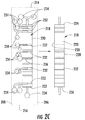
Figs. 2A - 2C show a cold box design according to the present disclosure that can be used for two up to five cores. These Figures show specifically fivecores 218 mounted in acold box 42. Thecold box 42 includes ahousing 204 that may be of structural steel and is shown in phantom in the drawings. Thehousing 204 is generally rectangular and includes for reference purposes a front 206, back 208, two spacedsides - There are five
cores 218 mounted in thehousing 204. Thecores 218 may be individual heat exchanger units, a non-limiting example of which is brazed aluminum plate fin heat exchangers. Thecores 218 are substantially rectangular in cross section, and include, for reference purposes, afront surface 220, backsurface 222,top surface 224,bottom surface 226 and spaced side surfaces 228 and 230. The fivecores 218 are mounted in thehousing 204 in a front-to-back relationship forming a single row along an axis extending from side to side in thehousing 2. In the embodiment shown inFigs. 2A-2C , the cores are spaced apart from one another. Thecores 218 are mounted in thehousing 204 with their front andback surfaces sides housing 204. Their side surfaces 228 face thefront 206 of thehousing 204 and theirside surfaces 230 face the back 208 of thehousing 204, respectively. - The
front surface 220, backsurface 222,top surface 224 andbottom surface 226 of each core in the design ofFigs. 2A - 2C havemanifolds 232 mounted thereon which communicate with the interior of thecore 218. As shown inFigs. 2A- 2C , with thecores 218 positioned within thehousing 204 as described, themanifolds 232 extend generally perpendicular to the axis of the row ofcores 218 and parallel to thesides housing 2. -
Headers 234 are provided that extend parallel to the axis of the row ofcores 218 with each extending in a plane parallel to the front 206 and back 208 of thehousing 204. Theheaders 234 extend perpendicular to themanifolds 232. Theheaders 234 extend through thesides cold box housing 204 and are adapted to be connected to conduits (not shown) provided on the outside of thecold box housing 204. For this purpose, theheaders 234 may be provided withcompanion flanges 235 at their open ends for connection to a similar flange provided on a conduit outside of the cold box. - As shown particularly in
Fig. 2C , there are thirteenheaders 234 positioned to the back side of thecores 218 between thecores 218 and the back 208 of the housing 202, while there are twoheaders 234 positioned above thecores 18 and one header positioned below thecores 218. There are no headers positioned in front of thecores 218 between thecores 218 and thefront 206 of the housing. The exact number ofheaders 234 depends upon the particular design and purpose of the heat exchanger units. - Individual feed lines 236 (only some of which are numbered) extend between each of the
headers 234 and itsrespective manifold 232 on each of the individual heat exchangers to provide a connection for flow from theheader 234 to themanifold 232. In the embodiment shown inFigs. 2A-2C , some of thefeed lines 236 have a configuration that includes afirst section 251 that is connected to a manifold 232 and extends in an X direction parallel to the axis of the row ofcores 218, a secondintermediate section 252 that is fluidly connected to thefirst section 251 and extends horizontally in a Z direction generally perpendicular to the axis of the row ofcores 218, and athird section 253 that is fluidly connected to theintermediate section 252 and extends vertically in a Y direction perpendicular to the axis of theheader 234 to which it is connected. As shown inFigs. 2A and2C , some of the feed lines have a curved shape that connects a manifold to a header that is perpendicular to the manifold. In some configurations (not shown), the first section of some of the feed lines extends horizontally in the X direction, the second intermediate section extends vertically in the Y direction, and the third section extends horizontally in the Z direction. - As mentioned previously, the
headers 234 may be used to convey such liquids and gases to and from theheat exchanger units 218 as warm feed gas (natural gas + methane refrigerant recycle), feed gas going to high pressure LNG, warm high pressure N2 refrigerant, boiloff gas being recirculated, cold low pressure N2 refrigerant and cold low pressure methane refrigerant. The particular liquid or gas being conveyed by the headers depends upon the particular cryogenic process. When the cold box is in use, the free volume within the cold box may be filled with an insulation material such as perlite. - As described above, in the arrangement as shown in
Figs. 2A - 2C , there are noheaders 234 orfeed lines 236 to the front of the front side surfaces 228 of thecores 218 between the front side surfaces 228 and thefront 206 of thehousing 204. In the event repair or replacement of acore 218 becomes necessary, a givencore 218 can be easily removed by opening thefront 206 of thehousing 204, disconnecting thefeed lines 236 to the desiredcore 218 and pulling thecore 218 outwardly as shown inFigures 2B and2C . There are noheaders 234 blocking the removal as there would be in the examples shown inFigures 1A and 1B . The design provides substantial maintenance cost savings due to the ease of core access and repair, and the reduction of downtime required for repair or replacement of the cores. Furthermore, the ability to remove and replace cores, servicing cores in need of repair at a location other than on a floating platform, provides flexibility in servicing options for the heat exchange units. Another advantage is that the removal and replacement of a core can be performed by the ship's own maintenance crew. The removed core in need of repair can then be serviced by the manufacturer at a future date. -
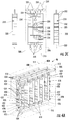
Figs. 3A - 3C show a design according to the present disclosure that can be used for six ormore cores 318. These Figures show specifically sixcores 318 mounted in thecold box 44. Thecold box 44 includes ahousing 304 that may be of structural steel and is shown in phantom in the drawings. Thehousing 304 is generally rectangular and includes for reference purposes a front 306, back 308, two spacedsides - There are six
cores 318 mounted in thehousing 2. Thecores 318 may be individual heat exchanger units, such as brazed aluminum plate fin heat exchangers. As in the previous designs, thecores 318 inFigs. 3A -C are substantially rectangular in cross section, and include, for reference purposes, afront surface 320, backsurface 322,top surface 324,bottom surface 326, aside surface 328 and aside surface 330. The sixcores 318 are arranged in two parallel rows with threecores 318 in each row. Thecores 318 in each row are in a front-to-back relationship. Each of the two rows extends along an axis extending from side to side in the housing 302. As such, thecores 318 are mounted in the housing 302 with their front andback surfaces sides housing 304 and theirside surfaces housing 304 respectively. - As with the
cores 218 shown inFigs. 2A - 2C , thefront surface 320, backsurface 322,top surface 324 andbottom surface 326 of each core 318 in the design ofFigs. 3A - 3C havemanifolds 332 mounted thereon which communicate with the interior of thecore 318. As shown inFigs. 3A- 3C , with thecores 318 positioned within thehousing 304 as described, themanifolds 332 extend generally perpendicular to the axis of the rows ofcores 18 and parallel to thesides housing 304. -
Headers 334 are provided that extend parallel to the axis of the row ofcores 318 with each extending in a plane parallel to the front 306 and back 308 of thehousing 304. Theheaders 334 extend perpendicular to themanifolds 332. Theseheaders 334 extend through thecold box housing 304 and are adapted to be connected to conduits (not shown) provided on the outside of thecold box housing 304. For this purpose, theheaders 334 may be provided withcompanion flanges 335 at their open ends for connection to a similar flange provided on a conduit outside of the cold box. - As shown particularly in
Fig. 3C there are fifteenheaders 334 extending in the space between the two rows ofcores 318 while each row has twoheaders 334 extending along the row above thecores 318 and oneheader 318 extending along the rows below the cores. Individual feed lines 336 (only some of which are numbered) extend between each of theheaders 334 and itsrespective manifold 332 on each of thecores 318 in a row to provide a connection for flow from theheader 334 to themanifold 332. As with previous designs, in use the free volume within the cold box may be filled with an insulation material such as perlite. - With the arrangement shown in
Figures 3A - 3C there are noheaders 334 positioned between theside 328 of the front row ofcores 318 and thefront 306 of thehousing 304. There are also noheaders 318 positioned between theside 330 of the back row of cores and the back 308 of thehousing 304. If it becomes necessary to remove acore 318 for repair or replacement, theindividual feed lines 336 to the given core can be disconnected and thecore 318 pulled out through the front 306 or back 308 of the housing 4 depending upon the row in which thecore 318 to be removed is located as shown inFigures 3B and3C . There are noheaders 334 blocking the removal. - In the embodiment shown in
Figs. 3A-3C , some of thefeed lines 336 have a configuration that includes a first section 351 that is connected to a manifold 332 and extends in an X direction parallel to the axis of the row ofcores 318, a second intermediate section 352 that is fluidly connected to the first section and extends horizontally in a Z direction generally perpendicular to the axis of the row ofcores 318, and a third section 353 that is fluidly connected to the second section and extends vertically in a Y direction perpendicular to the axis of theheader 334 to which it is connected. As shown inFigs. 3A and3C , some of the feed lines have a curved shape that connects the manifold to a header that is perpendicular to the manifold. In some configurations (not shown), the first section of some of the feed lines extends horizontally in the X direction, the second intermediate section extends vertically in the Y direction, and the third section extends horizontally in the Z direction. -
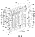
Figs. 4A - 4B show a design similar toFigures 3A - 3C but showing tencores 418 mounted in the cold box. Thecold box 46 includes ahousing 404 that may be of structural steel and is shown in phantom in the drawings. Thehousing 404 is generally rectangular and includes for reference purposes a front 406, back 408, two spacedsides - There are ten
cores 418 mounted in the housing 402. Thecores 418 may be individual heat exchanger units, such as brazed aluminum plate fin heat exchangers. As in the previous designs, thecores 418 inFigs. 4A -4C are substantially rectangular in cross section, and include, for reference purposes, afront surface 420, backsurface 422,top surface 424,bottom surface 426 and two spaced side surfaces 428 and 430. The sixcores 418 are arranged in two rows with fivecores 418 in each row. Thecores 418 in each row are in a front-to-back relationship. Each of the two rows extends along an axis extending from side to side in the housing 402. As such, thecores 418 are mounted in the housing 402 with their front andback surfaces sides housing 404 and theirside surfaces housing 404 respectively. If more cores are needed, they can be added to the end of each row. - The
front surface 420, backsurface 422,top surface 424 andbottom surface 426 of each core 418 in the design ofFigs. 4A - 4B havemanifolds 432 mounted thereon which communicate with the interior of thecore 418. As shown inFigs. 4A - 4B , with thecores 418 positioned within the housing 402 as described, themanifolds 432 extend generally perpendicular to the axis of the rows ofcores 418 and parallel to thesides -
Headers 434 are provided that extend parallel to the axis of the row ofcores 418 with each extending in a plane parallel to the front 406 and back 408 of thehousing 404. Theheaders 434 extend perpendicular to themanifolds 432. Theheaders 434 extend through theside walls cold box housing 404 and are adapted to be connected to conduits (not shown) provided on the outside of thecold box housing 404. For this purpose, theheaders 434 may be provided withcompanion flanges 435 at their open ends for connection to a similar flange provided on a conduit outside of the cold box. - As shown in
Figs. 4A , there are fifteenheaders 434 extending in the space between the two rows ofcores 418 while each row has twoheaders 434 extending along the row above thecores 418 and oneheader 418 extending along the row below the cores. Individual feed lines 436 (only some of which are numbered) extend between each of theheaders 434 and itsrespective manifold 432 on each of thecores 418 in a row to provide a connection for flow from theheader 434 to themanifold 432. The feed lines may have configurations similar to those described in connection withFigs. 3A-3C . As with previous designs, in use the free volume within the cold box may be filled with an insulating material such as perlite. - With the arrangement shown in
Figures 4A - 4C there are noheaders 418 positioned between the front row ofcores 418 and thefront 406 of thehousing 404 and no headers positioned between the back row of cores and the back 408 of thehousing 404. If it becomes necessary to remove acore 418 for repair or replacement, the individual feed lines to the givencore 418 can be disconnected and thecore 418 pulled out through the front 406 or back 408 of thehousing 404 depending upon the row in which thecore 418 to be removed is located as shown inFigures 4B . There are noheaders 434 blocking the removal. - The heat exchange units comprising the cold boxes described herein are typically configured to operate in the pressure range of 8963 kPa (1300 psig) or more, usually about 8693 to about 9653 kPa (1300 to about 1400 psig). The units typically have a minimum design operating temperature of -195 °C (-320 °F) or less, or -184 °C (-300 °F).
- The new cold boxes described herein have a variety of uses, and, as mentioned above, are particularly well-suited for inclusion in natural gas heat exchanger units, including LNG and FLNG units. The units can be maintained efficiently due to the ease of removal and replacement of cores needing repair.
- As indicated above, in embodiments, the size and/or weight of the cold box is increased as compared to the size and/or weight of a conventional system having generally the same capacity. In a typical cold box according to certain embodiments disclosed herein, the space between the cores will increase by about 10 - 50 %, or about 25 - 50 % as compared to a conventional system having the same capacity, resulting in certain circumstances in an overall increase in volume of the cold box of about 10 - 30 %, or about 20 - 30 %. In some cases, the configuration within the cold box will employ additional pipe fittings that may increase the weight of the cold box by about 5 - 20 %, or about 10 - 20 % as compared to a conventional cold box having the same capacity.
Claims (15)
- A cold box (42) including:a. at least one set of a plurality of cores (218) within a housing (204), each core (218) having a front (220), back (222), top (224), bottom (226) and side surface (228, 230), the cores (218) in each set positioned in a row in front-to-back relationship along an axis; whereinb. the housing (204) provides an enclosed structure;c. a plurality of headers (234) within the housing (204) are adapted to be connected to conduits outside of the housing (204), the headers (234) extending parallel to the axis of the row of cores (218); andd. feed lines (236) connect each of the headers (234) to a respective core (218);characterised by:the cores having a plurality of manifolds on their front and back surfaces; andthe headers being positioned to the top, bottom and/or rear of the cores with the space between one side of all the cores and the housing being free from the headers.
- The cold box (42) of claim 1 wherein the cores (218) comprise heat exchanger units.
- The cold box (42) of claim 1 wherein the plurality of cores (218) are arranged in two rows.
- The cold box (42) of claim 3 wherein the plurality of headers (234) are positioned to the top, bottom and between the rows of cores (218) with the space between one side (228, 230) of each of the cores (218) and the housing (204) being free from the headers (234).
- The cold box (42) of claim 1 wherein each of the plurality of headers (234) has a companion coupling (235) at its open end.
- The cold box (42) of claim 2 wherein the cores (218) comprise brazed aluminum heat exchangers.
- The cold box (42) of claim 1 wherein there is one set of cores (218) forming a single row, the row having up to five cores (218).
- The cold box (42) of claim 2 wherein the manifolds (232) extend perpendicular to the axis of the row in which the heat exchanger units are positioned.
- The cold box (42) of claim 1 wherein the headers (234) are positioned to the top, bottom and rear of the cores (218).
- The cold box of claim 1 wherein one side of each of the cores faces the front of the housing and the other side faces the back of the housing.
- The cold box of claim 1 wherein the axis of the row extends from side to side in the housing.
- The cold box of claim 9 wherein the headers (234) extend perpendicular to the manifolds (232).
- The cold box (42) of claim 1 wherein the cold box (42) is disposed on a floating liquefied natural gas production unit.
- A method of making a cold box (42), comprising:obtaining a housing (204) providing an enclosed structure with a removable side wall;disposing at least one set of a plurality of cores (218) within the housing (204), each core (218) having a front (220), back (222), top (224), bottom (226) and side surface (228, 230), the cores (218) in each set positioned in a row in front-to-back relationship along an axis;disposing a plurality of headers (234) within the housing (204), the headers (234) being configured to be connected to conduits outside of the housing (204), the headers (234) extending parallel to the axis of the row of cores (218); andconnecting each of the headers (234) to a respective core (218) using a feed line;characterised by:the cores having a plurality of manifolds on their front and back surfaces; andthe headers being positioned to the top, bottom and/or rear of the cores with the space between one side of all the cores and the housing being free from the headers.
- The method of claim 14, wherein each of the manifolds (232) extends perpendicular to the axis of the row in which the cores (218) are positioned.
Applications Claiming Priority (2)
| Application Number | Priority Date | Filing Date | Title |
|---|---|---|---|
| US13/453,597 US20130277021A1 (en) | 2012-04-23 | 2012-04-23 | Cold Box Design for Core Replacement |
| PCT/US2013/035780 WO2013162877A2 (en) | 2012-04-23 | 2013-04-09 | Cold box design for core replacement |
Publications (2)
| Publication Number | Publication Date |
|---|---|
| EP2861923A2 EP2861923A2 (en) | 2015-04-22 |
| EP2861923B1 true EP2861923B1 (en) | 2017-03-22 |
Family
ID=48143646
Family Applications (1)
| Application Number | Title | Priority Date | Filing Date |
|---|---|---|---|
| EP13718018.8A Revoked EP2861923B1 (en) | 2012-04-23 | 2013-04-09 | Cold box design for core replacement |
Country Status (6)
| Country | Link |
|---|---|
| US (1) | US20130277021A1 (en) |
| EP (1) | EP2861923B1 (en) |
| JP (1) | JP6140811B2 (en) |
| KR (1) | KR20150021919A (en) |
| CA (1) | CA2871631A1 (en) |
| WO (1) | WO2013162877A2 (en) |
Families Citing this family (7)
| Publication number | Priority date | Publication date | Assignee | Title |
|---|---|---|---|---|
| NO337356B1 (en) * | 2014-04-22 | 2016-03-21 | Aker Engineering & Tech As | processing plants |
| JP6657199B2 (en) * | 2014-10-07 | 2020-03-04 | ユニゾン・インダストリーズ,エルエルシー | Multi-branch branch flow heat exchanger |
| US11892245B2 (en) | 2014-10-07 | 2024-02-06 | General Electric Company | Heat exchanger including furcating unit cells |
| FR3066265B1 (en) * | 2017-05-11 | 2021-01-01 | Air Liquide | HEAT EXCHANGER |
| FR3101141B1 (en) * | 2019-09-24 | 2023-04-14 | Air Liquide | HEAT EXCHANGER, DUAL REFRIGERATION CYCLE LIQUEFACTION SYSTEM COMPRISING SUCH HEAT EXCHANGER |
| FR3120428B1 (en) * | 2021-03-04 | 2024-01-05 | Arianegroup Sas | Maintenance method for a gas liquefaction device |
| FR3120430B1 (en) * | 2021-03-04 | 2024-01-05 | Arianegroup Sas | Gas liquefaction device and method of assembling such a device |
Citations (5)
| Publication number | Priority date | Publication date | Assignee | Title |
|---|---|---|---|---|
| US4524728A (en) | 1983-07-25 | 1985-06-25 | Electric Power Research Institute, Inc. | Steam condensing apparatus |
| JPH1147279A (en) | 1997-07-29 | 1999-02-23 | Tomoaki Otsuka | Improvement of biological balance and activation |
| US6250244B1 (en) | 1995-10-05 | 2001-06-26 | Bhp Petroleum Pty Ltd | Liquefaction apparatus |
| US6349566B1 (en) | 2000-09-15 | 2002-02-26 | Air Products And Chemicals, Inc. | Dephlegmator system and process |
| WO2006069983A1 (en) | 2004-12-30 | 2006-07-06 | L'air Liquide, Societe Anonyme Pour L'etude Et L'exploitation Des Procedes Georges Claude | Assembly of heat exchangers and a cryogenic distillation apparatus incorporating the same |
Family Cites Families (13)
| Publication number | Priority date | Publication date | Assignee | Title |
|---|---|---|---|---|
| JPS4947086Y1 (en) * | 1969-05-09 | 1974-12-24 | ||
| JPH0789008B2 (en) * | 1987-12-04 | 1995-09-27 | 日本酸素株式会社 | Condensing evaporator |
| US4962810A (en) * | 1989-09-18 | 1990-10-16 | Rockwell International Corporation | Heat exchanger |
| JPH07243760A (en) * | 1994-03-07 | 1995-09-19 | Kobe Steel Ltd | Heat exchanger |
| US5755114A (en) | 1997-01-06 | 1998-05-26 | Abb Randall Corporation | Use of a turboexpander cycle in liquefied natural gas process |
| US6092591A (en) * | 1999-10-08 | 2000-07-25 | Abb Alstom Power Inc. | Top mounting arrangement for a heat exchange module |
| US6412302B1 (en) | 2001-03-06 | 2002-07-02 | Abb Lummus Global, Inc. - Randall Division | LNG production using dual independent expander refrigeration cycles |
| JP3565276B2 (en) * | 2002-05-14 | 2004-09-15 | 木村工機株式会社 | Heat pump type air conditioner |
| US6889522B2 (en) | 2002-06-06 | 2005-05-10 | Abb Lummus Global, Randall Gas Technologies | LNG floating production, storage, and offloading scheme |
| BRPI0511785B8 (en) * | 2004-06-23 | 2018-04-24 | Exxonmobil Upstream Res Co | methods for liquefying a natural gas stream |
| US7779899B2 (en) * | 2006-06-19 | 2010-08-24 | Praxair Technology, Inc. | Plate-fin heat exchanger having application to air separation |
| US20110139417A1 (en) * | 2009-12-16 | 2011-06-16 | Uop Llc | Method for making brazed aluminum heat exchanger and apparatus |
| JP5660845B2 (en) * | 2010-10-13 | 2015-01-28 | 三菱重工業株式会社 | Liquefaction method, liquefaction apparatus, and floating liquefied gas production facility equipped with the same |
-
2012
- 2012-04-23 US US13/453,597 patent/US20130277021A1/en not_active Abandoned
-
2013
- 2013-04-09 EP EP13718018.8A patent/EP2861923B1/en not_active Revoked
- 2013-04-09 JP JP2015509001A patent/JP6140811B2/en not_active Expired - Fee Related
- 2013-04-09 CA CA2871631A patent/CA2871631A1/en not_active Abandoned
- 2013-04-09 WO PCT/US2013/035780 patent/WO2013162877A2/en active Application Filing
- 2013-04-09 KR KR20147032685A patent/KR20150021919A/en not_active Application Discontinuation
Patent Citations (5)
| Publication number | Priority date | Publication date | Assignee | Title |
|---|---|---|---|---|
| US4524728A (en) | 1983-07-25 | 1985-06-25 | Electric Power Research Institute, Inc. | Steam condensing apparatus |
| US6250244B1 (en) | 1995-10-05 | 2001-06-26 | Bhp Petroleum Pty Ltd | Liquefaction apparatus |
| JPH1147279A (en) | 1997-07-29 | 1999-02-23 | Tomoaki Otsuka | Improvement of biological balance and activation |
| US6349566B1 (en) | 2000-09-15 | 2002-02-26 | Air Products And Chemicals, Inc. | Dephlegmator system and process |
| WO2006069983A1 (en) | 2004-12-30 | 2006-07-06 | L'air Liquide, Societe Anonyme Pour L'etude Et L'exploitation Des Procedes Georges Claude | Assembly of heat exchangers and a cryogenic distillation apparatus incorporating the same |
Also Published As
| Publication number | Publication date |
|---|---|
| EP2861923A2 (en) | 2015-04-22 |
| KR20150021919A (en) | 2015-03-03 |
| WO2013162877A3 (en) | 2015-04-02 |
| JP2015522782A (en) | 2015-08-06 |
| JP6140811B2 (en) | 2017-05-31 |
| CA2871631A1 (en) | 2013-10-31 |
| US20130277021A1 (en) | 2013-10-24 |
| WO2013162877A2 (en) | 2013-10-31 |
Similar Documents
| Publication | Publication Date | Title |
|---|---|---|
| EP2861923B1 (en) | Cold box design for core replacement | |
| US10060670B2 (en) | Air-cooled modular LNG production facility | |
| RU2767239C2 (en) | Container unit of natural gas liquefaction and method for producing lns using this unit | |
| EP2157013B1 (en) | Liquefied gas storage tank and marine structure including the same | |
| US6994104B2 (en) | Modular system for storing gas cylinders | |
| CA2419956C (en) | Methods and apparatus for compressed gas | |
| US20140069931A1 (en) | Liquefied natural gas storage container and method for manufacturing the same | |
| KR101419824B1 (en) | Container for storing liquefied natural gas | |
| WO2020129148A1 (en) | Floating facility | |
| US20100319877A1 (en) | Removable Flow Diversion Baffles for Liquefied Natural Gas Heat Exchangers | |
| KR102120558B1 (en) | Insulation System of Liquefied Gas Storage Tank and Ship having the same | |
| KR200462375Y1 (en) | Apparatus for collecting leakage of an independence type storage tank | |
| EP3674644B1 (en) | Heat exchanger assembly and method for assembling same | |
| US11592234B2 (en) | Hydrocarbon fluid liquefaction system installation and system therefor | |
| CN202382519U (en) | Cold box of cryogenic separation device | |
| Miller et al. | Application, Design and Operation Considerations for Brazed Aluminum Heat Exchangers in Liquefied Natural Gas Service | |
| KR20100122556A (en) | Membrane type lng storage tank having a structure in two rows | |
| KR101599294B1 (en) | Loading and unloading apparatus for storage tanks and floating structure having the apparatus | |
| KR101115465B1 (en) | Apparatus for producing liquefied natural gas | |
| WO2018150216A1 (en) | Method and hollow structure for cooling a heat transfer fluid |
Legal Events
| Date | Code | Title | Description |
|---|---|---|---|
| PUAI | Public reference made under article 153(3) epc to a published international application that has entered the european phase |
Free format text: ORIGINAL CODE: 0009012 |
|
| 17P | Request for examination filed |
Effective date: 20141121 |
|
| AK | Designated contracting states |
Kind code of ref document: A2 Designated state(s): AL AT BE BG CH CY CZ DE DK EE ES FI FR GB GR HR HU IE IS IT LI LT LU LV MC MK MT NL NO PL PT RO RS SE SI SK SM TR |
|
| AX | Request for extension of the european patent |
Extension state: BA ME |
|
| R17D | Deferred search report published (corrected) |
Effective date: 20150402 |
|
| R17P | Request for examination filed (corrected) |
Effective date: 20150427 |
|
| RBV | Designated contracting states (corrected) |
Designated state(s): AL AT BE BG CH CY CZ DE DK EE ES FI FR GB GR HR HU IE IS IT LI LT LU LV MC MK MT NL NO PL PT RO RS SE SI SK SM TR |
|
| DAX | Request for extension of the european patent (deleted) | ||
| GRAP | Despatch of communication of intention to grant a patent |
Free format text: ORIGINAL CODE: EPIDOSNIGR1 |
|
| INTG | Intention to grant announced |
Effective date: 20161010 |
|
| GRAS | Grant fee paid |
Free format text: ORIGINAL CODE: EPIDOSNIGR3 |
|
| STAA | Information on the status of an ep patent application or granted ep patent |
Free format text: STATUS: GRANT OF PATENT IS INTENDED |
|
| GRAA | (expected) grant |
Free format text: ORIGINAL CODE: 0009210 |
|
| STAA | Information on the status of an ep patent application or granted ep patent |
Free format text: STATUS: THE PATENT HAS BEEN GRANTED |
|
| AK | Designated contracting states |
Kind code of ref document: B1 Designated state(s): AL AT BE BG CH CY CZ DE DK EE ES FI FR GB GR HR HU IE IS IT LI LT LU LV MC MK MT NL NO PL PT RO RS SE SI SK SM TR |
|
| REG | Reference to a national code |
Ref country code: GB Ref legal event code: FG4D |
|
| REG | Reference to a national code |
Ref country code: CH Ref legal event code: EP |
|
| REG | Reference to a national code |
Ref country code: AT Ref legal event code: REF Ref document number: 878200 Country of ref document: AT Kind code of ref document: T Effective date: 20170415 |
|
| REG | Reference to a national code |
Ref country code: IE Ref legal event code: FG4D |
|
| REG | Reference to a national code |
Ref country code: DE Ref legal event code: R096 Ref document number: 602013018871 Country of ref document: DE |
|
| REG | Reference to a national code |
Ref country code: NL Ref legal event code: MP Effective date: 20170322 |
|
| PG25 | Lapsed in a contracting state [announced via postgrant information from national office to epo] |
Ref country code: NO Free format text: LAPSE BECAUSE OF FAILURE TO SUBMIT A TRANSLATION OF THE DESCRIPTION OR TO PAY THE FEE WITHIN THE PRESCRIBED TIME-LIMIT Effective date: 20170622 Ref country code: FI Free format text: LAPSE BECAUSE OF FAILURE TO SUBMIT A TRANSLATION OF THE DESCRIPTION OR TO PAY THE FEE WITHIN THE PRESCRIBED TIME-LIMIT Effective date: 20170322 Ref country code: HR Free format text: LAPSE BECAUSE OF FAILURE TO SUBMIT A TRANSLATION OF THE DESCRIPTION OR TO PAY THE FEE WITHIN THE PRESCRIBED TIME-LIMIT Effective date: 20170322 Ref country code: LT Free format text: LAPSE BECAUSE OF FAILURE TO SUBMIT A TRANSLATION OF THE DESCRIPTION OR TO PAY THE FEE WITHIN THE PRESCRIBED TIME-LIMIT Effective date: 20170322 Ref country code: GR Free format text: LAPSE BECAUSE OF FAILURE TO SUBMIT A TRANSLATION OF THE DESCRIPTION OR TO PAY THE FEE WITHIN THE PRESCRIBED TIME-LIMIT Effective date: 20170623 |
|
| REG | Reference to a national code |
Ref country code: LT Ref legal event code: MG4D |
|
| REG | Reference to a national code |
Ref country code: AT Ref legal event code: MK05 Ref document number: 878200 Country of ref document: AT Kind code of ref document: T Effective date: 20170322 |
|
| PG25 | Lapsed in a contracting state [announced via postgrant information from national office to epo] |
Ref country code: LV Free format text: LAPSE BECAUSE OF FAILURE TO SUBMIT A TRANSLATION OF THE DESCRIPTION OR TO PAY THE FEE WITHIN THE PRESCRIBED TIME-LIMIT Effective date: 20170322 Ref country code: RS Free format text: LAPSE BECAUSE OF FAILURE TO SUBMIT A TRANSLATION OF THE DESCRIPTION OR TO PAY THE FEE WITHIN THE PRESCRIBED TIME-LIMIT Effective date: 20170322 Ref country code: SE Free format text: LAPSE BECAUSE OF FAILURE TO SUBMIT A TRANSLATION OF THE DESCRIPTION OR TO PAY THE FEE WITHIN THE PRESCRIBED TIME-LIMIT Effective date: 20170322 Ref country code: BG Free format text: LAPSE BECAUSE OF FAILURE TO SUBMIT A TRANSLATION OF THE DESCRIPTION OR TO PAY THE FEE WITHIN THE PRESCRIBED TIME-LIMIT Effective date: 20170622 |
|
| PG25 | Lapsed in a contracting state [announced via postgrant information from national office to epo] |
Ref country code: NL Free format text: LAPSE BECAUSE OF FAILURE TO SUBMIT A TRANSLATION OF THE DESCRIPTION OR TO PAY THE FEE WITHIN THE PRESCRIBED TIME-LIMIT Effective date: 20170322 |
|
| PG25 | Lapsed in a contracting state [announced via postgrant information from national office to epo] |
Ref country code: RO Free format text: LAPSE BECAUSE OF FAILURE TO SUBMIT A TRANSLATION OF THE DESCRIPTION OR TO PAY THE FEE WITHIN THE PRESCRIBED TIME-LIMIT Effective date: 20170322 Ref country code: AT Free format text: LAPSE BECAUSE OF FAILURE TO SUBMIT A TRANSLATION OF THE DESCRIPTION OR TO PAY THE FEE WITHIN THE PRESCRIBED TIME-LIMIT Effective date: 20170322 Ref country code: IT Free format text: LAPSE BECAUSE OF FAILURE TO SUBMIT A TRANSLATION OF THE DESCRIPTION OR TO PAY THE FEE WITHIN THE PRESCRIBED TIME-LIMIT Effective date: 20170322 Ref country code: ES Free format text: LAPSE BECAUSE OF FAILURE TO SUBMIT A TRANSLATION OF THE DESCRIPTION OR TO PAY THE FEE WITHIN THE PRESCRIBED TIME-LIMIT Effective date: 20170322 Ref country code: EE Free format text: LAPSE BECAUSE OF FAILURE TO SUBMIT A TRANSLATION OF THE DESCRIPTION OR TO PAY THE FEE WITHIN THE PRESCRIBED TIME-LIMIT Effective date: 20170322 Ref country code: CZ Free format text: LAPSE BECAUSE OF FAILURE TO SUBMIT A TRANSLATION OF THE DESCRIPTION OR TO PAY THE FEE WITHIN THE PRESCRIBED TIME-LIMIT Effective date: 20170322 Ref country code: SK Free format text: LAPSE BECAUSE OF FAILURE TO SUBMIT A TRANSLATION OF THE DESCRIPTION OR TO PAY THE FEE WITHIN THE PRESCRIBED TIME-LIMIT Effective date: 20170322 |
|
| REG | Reference to a national code |
Ref country code: DE Ref legal event code: R119 Ref document number: 602013018871 Country of ref document: DE |
|
| PG25 | Lapsed in a contracting state [announced via postgrant information from national office to epo] |
Ref country code: IS Free format text: LAPSE BECAUSE OF FAILURE TO SUBMIT A TRANSLATION OF THE DESCRIPTION OR TO PAY THE FEE WITHIN THE PRESCRIBED TIME-LIMIT Effective date: 20170722 Ref country code: PT Free format text: LAPSE BECAUSE OF FAILURE TO SUBMIT A TRANSLATION OF THE DESCRIPTION OR TO PAY THE FEE WITHIN THE PRESCRIBED TIME-LIMIT Effective date: 20170724 Ref country code: PL Free format text: LAPSE BECAUSE OF FAILURE TO SUBMIT A TRANSLATION OF THE DESCRIPTION OR TO PAY THE FEE WITHIN THE PRESCRIBED TIME-LIMIT Effective date: 20170322 Ref country code: SM Free format text: LAPSE BECAUSE OF FAILURE TO SUBMIT A TRANSLATION OF THE DESCRIPTION OR TO PAY THE FEE WITHIN THE PRESCRIBED TIME-LIMIT Effective date: 20170322 |
|
| REG | Reference to a national code |
Ref country code: CH Ref legal event code: PL |
|
| PLBI | Opposition filed |
Free format text: ORIGINAL CODE: 0009260 |
|
| PLAX | Notice of opposition and request to file observation + time limit sent |
Free format text: ORIGINAL CODE: EPIDOSNOBS2 |
|
| 26 | Opposition filed |
Opponent name: L'AIR LIQUIDE, SOCIETE ANONYME POUR L'ETUDE ET L'E Effective date: 20171221 |
|
| REG | Reference to a national code |
Ref country code: IE Ref legal event code: MM4A |
|
| REG | Reference to a national code |
Ref country code: FR Ref legal event code: ST Effective date: 20171229 |
|
| PG25 | Lapsed in a contracting state [announced via postgrant information from national office to epo] |
Ref country code: FR Free format text: LAPSE BECAUSE OF NON-PAYMENT OF DUE FEES Effective date: 20170522 Ref country code: DE Free format text: LAPSE BECAUSE OF NON-PAYMENT OF DUE FEES Effective date: 20171103 Ref country code: MC Free format text: LAPSE BECAUSE OF FAILURE TO SUBMIT A TRANSLATION OF THE DESCRIPTION OR TO PAY THE FEE WITHIN THE PRESCRIBED TIME-LIMIT Effective date: 20170322 Ref country code: DK Free format text: LAPSE BECAUSE OF FAILURE TO SUBMIT A TRANSLATION OF THE DESCRIPTION OR TO PAY THE FEE WITHIN THE PRESCRIBED TIME-LIMIT Effective date: 20170322 |
|
| GBPC | Gb: european patent ceased through non-payment of renewal fee |
Effective date: 20170622 |
|
| PG25 | Lapsed in a contracting state [announced via postgrant information from national office to epo] |
Ref country code: CH Free format text: LAPSE BECAUSE OF NON-PAYMENT OF DUE FEES Effective date: 20170430 Ref country code: LI Free format text: LAPSE BECAUSE OF NON-PAYMENT OF DUE FEES Effective date: 20170430 Ref country code: SI Free format text: LAPSE BECAUSE OF FAILURE TO SUBMIT A TRANSLATION OF THE DESCRIPTION OR TO PAY THE FEE WITHIN THE PRESCRIBED TIME-LIMIT Effective date: 20170322 Ref country code: LU Free format text: LAPSE BECAUSE OF NON-PAYMENT OF DUE FEES Effective date: 20170409 |
|
| REG | Reference to a national code |
Ref country code: BE Ref legal event code: MM Effective date: 20170430 |
|
| PG25 | Lapsed in a contracting state [announced via postgrant information from national office to epo] |
Ref country code: GB Free format text: LAPSE BECAUSE OF NON-PAYMENT OF DUE FEES Effective date: 20170622 Ref country code: IE Free format text: LAPSE BECAUSE OF NON-PAYMENT OF DUE FEES Effective date: 20170409 |
|
| PG25 | Lapsed in a contracting state [announced via postgrant information from national office to epo] |
Ref country code: BE Free format text: LAPSE BECAUSE OF NON-PAYMENT OF DUE FEES Effective date: 20170430 |
|
| RDAF | Communication despatched that patent is revoked |
Free format text: ORIGINAL CODE: EPIDOSNREV1 |
|
| PG25 | Lapsed in a contracting state [announced via postgrant information from national office to epo] |
Ref country code: MT Free format text: LAPSE BECAUSE OF NON-PAYMENT OF DUE FEES Effective date: 20170409 |
|
| RDAG | Patent revoked |
Free format text: ORIGINAL CODE: 0009271 |
|
| STAA | Information on the status of an ep patent application or granted ep patent |
Free format text: STATUS: PATENT REVOKED |
|
| 27W | Patent revoked |
Effective date: 20180924 |
|
| PG25 | Lapsed in a contracting state [announced via postgrant information from national office to epo] |
Ref country code: MK Free format text: LAPSE BECAUSE OF FAILURE TO SUBMIT A TRANSLATION OF THE DESCRIPTION OR TO PAY THE FEE WITHIN THE PRESCRIBED TIME-LIMIT Effective date: 20170322 |
|
| PG25 | Lapsed in a contracting state [announced via postgrant information from national office to epo] |
Ref country code: CY Free format text: LAPSE BECAUSE OF FAILURE TO SUBMIT A TRANSLATION OF THE DESCRIPTION OR TO PAY THE FEE WITHIN THE PRESCRIBED TIME-LIMIT Effective date: 20170322 |
|
| PG25 | Lapsed in a contracting state [announced via postgrant information from national office to epo] |
Ref country code: AL Free format text: LAPSE BECAUSE OF FAILURE TO SUBMIT A TRANSLATION OF THE DESCRIPTION OR TO PAY THE FEE WITHIN THE PRESCRIBED TIME-LIMIT Effective date: 20170322 |
|
| PG25 | Lapsed in a contracting state [announced via postgrant information from national office to epo] |
Ref country code: TR Free format text: LAPSE BECAUSE OF FAILURE TO SUBMIT A TRANSLATION OF THE DESCRIPTION OR TO PAY THE FEE WITHIN THE PRESCRIBED TIME-LIMIT Effective date: 20170322 |