EP2861904B1 - Verbesserte installationsvorrichtung - Google Patents
Verbesserte installationsvorrichtung Download PDFInfo
- Publication number
- EP2861904B1 EP2861904B1 EP13736936.9A EP13736936A EP2861904B1 EP 2861904 B1 EP2861904 B1 EP 2861904B1 EP 13736936 A EP13736936 A EP 13736936A EP 2861904 B1 EP2861904 B1 EP 2861904B1
- Authority
- EP
- European Patent Office
- Prior art keywords
- pipe
- engagement portion
- branch
- existing pipe
- passageway
- Prior art date
- Legal status (The legal status is an assumption and is not a legal conclusion. Google has not performed a legal analysis and makes no representation as to the accuracy of the status listed.)
- Active
Links
Images



Classifications
-
- F—MECHANICAL ENGINEERING; LIGHTING; HEATING; WEAPONS; BLASTING
- F16—ENGINEERING ELEMENTS AND UNITS; GENERAL MEASURES FOR PRODUCING AND MAINTAINING EFFECTIVE FUNCTIONING OF MACHINES OR INSTALLATIONS; THERMAL INSULATION IN GENERAL
- F16L—PIPES; JOINTS OR FITTINGS FOR PIPES; SUPPORTS FOR PIPES, CABLES OR PROTECTIVE TUBING; MEANS FOR THERMAL INSULATION IN GENERAL
- F16L41/00—Branching pipes; Joining pipes to walls
- F16L41/08—Joining pipes to walls or pipes, the joined pipe axis being perpendicular to the plane of a wall or to the axis of another pipe
- F16L41/12—Joining pipes to walls or pipes, the joined pipe axis being perpendicular to the plane of a wall or to the axis of another pipe using attaching means embracing the pipe
-
- F—MECHANICAL ENGINEERING; LIGHTING; HEATING; WEAPONS; BLASTING
- F16—ENGINEERING ELEMENTS AND UNITS; GENERAL MEASURES FOR PRODUCING AND MAINTAINING EFFECTIVE FUNCTIONING OF MACHINES OR INSTALLATIONS; THERMAL INSULATION IN GENERAL
- F16L—PIPES; JOINTS OR FITTINGS FOR PIPES; SUPPORTS FOR PIPES, CABLES OR PROTECTIVE TUBING; MEANS FOR THERMAL INSULATION IN GENERAL
- F16L41/00—Branching pipes; Joining pipes to walls
- F16L41/08—Joining pipes to walls or pipes, the joined pipe axis being perpendicular to the plane of a wall or to the axis of another pipe
- F16L41/082—Non-disconnectable joints, e.g. soldered, adhesive or caulked joints
Definitions
- the present invention relates to an improved apparatus for permitting the addition of a branch pipe to an existing pipe.
- US Patent US 1 908 821 relates to a metal branch fitting, which consists of a metal saddle portion which snugly fits around part of the external circumference of a main pipe.
- the saddle is sized to envelop greater than half of the circumference to embrace the outer wall of the pipe to which the saddle is being attached.
- the saddle is soldered, welded or brazed to the outer pipe wall.
- an apparatus for attaching a branch pipe to an existing pipe comprising:
- providing an apparatus in which the attachment mechanism is provided adjacent the passageway permits the apparatus to be attached to an existing pipe which is only partially exposed. This is of use, for example, where the pipe is buried or where the pipe is located underneath the floor.
- Such an arrangement ensures the branch can be added with minimal damage to the surrounding environment, for example without the need to lift large numbers of floorboards or dig a large hole to provide access to all sides of the pipe.
- a hole is cut in the existing pipe and the apparatus engages with the surface of the existing pipe around the hole, the passageway providing fluid communication through the existing pipe hole to a branch pipe attached to the apparatus.
- the passageway may be defined by a wall having a perimeter and the pipe engagement portion may extend around the circumference of perimeter of the passageway wall.
- the passageway wall may extend through the pipe engagement portion.
- the pipe engagement portion defines a curved engagement surface for engaging the surface of an existing pipe where in use, the curve of the engagement surface may be the same radius as the radius of the external surface of the existing pipe.
- a curved engagement surface permits a snug fit between the apparatus and the existing pipe.
- the pipe engagement portion is resilient.
- the pipe engagement portion may define a curved engagement surface for engaging the surface of the existing pipe.
- the engagement surface may have a radius less than the radius of the external surface of the existing pipe.
- the resilient nature of the pipe engagement portion and the pipe engagement portion having a radius less than the radius of the external surface of the existing pipe permits pipe engagement portion to snap fit around the existing pipe. This arrangement also permits a single apparatus to fit a number of different radii.
- the first attachment mechanism and the pipe engagement portion may be the same. In an embodiment where the pipe engagement portion snap fits around the existing pipe, this may be sufficient to provide a robust and leak free engagement between the apparatus and the existing pipe.
- the pipe engagement portion engaging surface may be adapted to seal against the existing pipe surface.
- the pipe engagement portion may include a gasket, seal or similar mechanism or a sealing material to provide a seal between the apparatus on the existing pipe surface.
- the pipe engagement portion engaging surface may be adapted to be adhered to the existing pipe surface.
- the apparatus may be glued to the existing pipe surface. In an embodiment, where there is adherence between the existing pipe surface and the apparatus, the adherence is sufficient to provide a seal between the two components.
- the apparatus may be provided with an adhering layer applied to the pipe engagement portion engagement surface.
- the extended passageway wall may further comprise a seal for sealing against a hole cut in the existing pipe to receive the passageway wall.
- the seal may be adapted to seal against an internal surface of the existing pipe.
- the apparatus may be arranged such that the seal can be sealed against the internal surface of the existing pipe by application of an energising force applied from the external side of the existing pipe. Particularly the energising force may be applied through the passageway.
- a seal can be made between the apparatus and either the edges of the existing pipe hole or the internal surface of the existing pipe by applying a pull, push or twisting force (or a combination of these) from the outside of the existing pipe through the passageway. This allows the seal between the apparatus and the existing pipe to be made securely and easily.
- the branch engagement portion may define a wall.
- a branch pipe may be received within the branch engagement portion wall.
- the branch engagement portion wall may be received within a branch pipe.
- the passageway may be of a smaller diameter than the branch engagement portion.
- the branch engagement portion may define a transition section providing a continuous surface from the branch engagement portion wall to the passageway wall.
- the first attachment mechanism may be a mechanical fixing.
- a second attachment mechanism adds strength to the engagement between the apparatus and existing pipe resulting in a more secure and potentially better and/or tighter seal between the two components.
- the second attachment mechanism may, in use, pierce the existing pipe.
- applying a mechanical fixing through the branch engagement portion transition section ensures that should the mechanical fixing pierce the wall of the existing pipe, any leakage between the second attachment mechanism and the existing pipe, will be through the branch engagement portion transition section and into, in use, the branch pipe. This ensures any leakage is retained within the plumbing system and not the external environment.
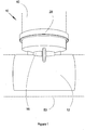
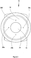
- FIGS. 1 and 2 and 3 side, top and front views of an apparatus, generally indicated by reference numeral 10 for attaching a branch pipe 40 (shown in broken outline) to an existing pipe 50 (shown in broken outline).
- the apparatus 10 comprises a pipe engagement portion 12 adapted to engage the surface of the existing pipe 50 (shown in later Figures).
- the apparatus 10 further comprises a branch engagement portion 14 adapted to receive the end of the branch pipe 40 to be connected to the existing pipe 50.
- the pipe engagement portion 12 and the branch engagement portion 14 are in fluid communication by means of a passageway 16 defined by a passageway wall 18. It will be noted that the passageway wall 18 extends through the pipe engagement portion 12. The purpose of this will be discussed in due course
- the pipe engagement portion 12 comprises a resilient polymer which is adapted to snap fit around the existing pipe 50 providing a first attachment mechanism 20 for attaching the apparatus 10 to an existing pipe.
- the first attachment mechanism 20, in the form of the pipe engagement portion 12 extends from the passageway 16.
- a second attachment mechanism 26 is provided in a transition section 24 of the branch engagement portion 14.
- the transition section 24 provides a transition from the branch engagement portion wall 22 to the passageway wall 18.
- the passageway 16 has a smaller diameter than the branch engagement portion 14 and the provision of a transition section 24 to link the two permits a second attachment means 22 to be situated within the branch engagement portion 14.
- the second attachment means are four holes 26a-d which pass through fins 28 extending perpendicularly from, and are integral with, the passageway wall 18.
- the four holes 26a-d are adapted to receive screws which can be screwed through the apparatus 10 into the surface of the existing pipe 50.
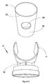
- Figure 4 and 5 are perspective views of the apparatus 10 and the section of existing pipe 50.
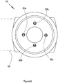
- Figure 6 is a front view of the apparatus 10 attached to the existing pipe 50 and
- Figure 7 is a top view of the apparatus 10 attached to the existing pipe 50 and the branch pipe 40.
- the existing pipe 50 has a hole 54 drilled through the pipe surface 52 and the wall 56 of the pipe 50. It will be seen most clearly from Figure 5 that the radius of the pipe engagement portion 12 is smaller than the radius of the pipe 50.
- the pipe engagement portion 12 is a resilient material, it can be pushed onto the pipe 50 such that the passageway wall 18 extends into the hole 54 drilled in the existing pipe wall 56.
- an adhesive is spread over the pipe engagement portion surface to adhere the apparatus 10 to the pipe 50.
- the pipe engagement portion 12 snaps over the existing pipe 50 and forms a seal with the existing pipe 50 around the passageway 16.
- the second attachment mechanism is then utilised by screwing for screws 30a-d into the existing pipe 50, thereby strengthening the engagement between the apparatus 10 and the existing pipe 50.
- the branch pipe 40 is then inserted into the branch engagement portion 14, the branch seal 28 sealing against the branch pipe surface 42.
- the pipe engaging portion may not extend so far around the existing pipe and the snap fit function may not be provided. This permits the apparatus 10 to be fitted to pipe which is less external surface exposed due to its location in a recess or having been buried for example.
Landscapes
- Engineering & Computer Science (AREA)
- General Engineering & Computer Science (AREA)
- Mechanical Engineering (AREA)
- Branch Pipes, Bends, And The Like (AREA)
- Domestic Plumbing Installations (AREA)
Claims (14)
- Vorrichtung (10) zum Befestigen eines Abzweigrohrs (40) an einem bestehenden Rohr (50), wobei die Vorrichtung umfasst:einen Rohreingriffsabschnitt (12), der angepasst ist, um mit der Oberfläche eines existierenden Rohres in Eingriff zu kommen;einen Zweigeingriffsabschnitt (14), der angepasst ist, um ein Ende eines Abzweigrohrs, das mit dem existierenden Rohr zu verbinden ist, aufzunehmen, wobei der Zweigeingriffsabschnitt eine Zweigeingriffsabschnittswand (22) definiert;einen Durchgang (16), der eine Fluidverbindung zwischen dem Rohreingriffsabschnitt und dem Zweigeingriffsabschnitt (14) bereitstellt, wobei der Durchgang (16) von einer Durchgangswand (18) definiert ist und der Durchgang (16) einen kleineren Durchmesser als der Zweigeingriffsabschnitt (14) aufweist;wobei der Zweigeingriffsabschnitt einen Übergangsbereich (24) definiert, der eine kontinuierliche Oberfläche von der Zweigeingriffsabschnittswand zu der Durchgangswand (18) bereitstellt;einen ersten Befestigungsmechanismus (20) zum Befestigen der Vorrichtung (10) an einem bestehenden Rohr;wobei der erste Befestigungsmechanismus (20) benachbart zu dem Durchgang (16) vorgesehen ist; undeinen zweiten Befestigungsmechanismus (26) zum Befestigen der Vorrichtung an dem bestehenden Rohr (50);dadurch gekennzeichnet, dass der zweite Befestigungsmechanismus (26) durch den Übergangsbereich (24) des Zweigeingriffsabschnitts aufgebracht ist.
- Vorrichtung nach Anspruch 1, wobei die Durchgangswand (18) einen Perimeter aufweist und der Rohreingriffsabschnitt (12) sich um den Umfang des Perimeters der Durchgangswand (18) erstreckt.
- Vorrichtung nach einem vorstehenden Anspruch, wobei sich die Durchgangswand (18) durch den Rohreingriffsabschnitt (12) erstreckt.
- Vorrichtung nach einem vorstehenden Anspruch, wobei der Rohreingriffsabschnitt (12) eine gekrümmte Eingriffsoberfläche zum in Eingriff bringen der Oberfläche eines bestehenden Rohrs (50) definiert, wobei, im Gebrauch, die Krümmung der Eingriffsoberfläche den gleichen Radius wie der Radius der äußeren Oberfläche des bestehenden Rohrs (50) aufweist.
- Vorrichtung nach Anspruch 4, wobei der Rohreingriffsabschnitt (12) elastisch ist und der Rohreingriffsabschnitt (12) eine gekrümmte Eingriffsoberfläche zum in Eingriff bringen der Oberfläche eines bestehenden Rohrs (50) definiert, wobei, im Gebrauch, die Eingriffsoberfläche einen Radius aufweist, der kleiner als der Radius der äußeren Oberfläche des bestehenden Rohrs (50) ist.
- Vorrichtung nach Anspruch 4 oder 5, wobei die Eingriffsoberfläche des Rohreingriffsabschnitts (12) angepasst ist, um gegen die Oberfläche des bestehenden Rohrs (50) abzudichten, wobei der Rohreingriffsabschnitt (12) eine Dichtung, eine Abdichtung oder einen ähnlichen Mechanismus oder ein Dichtungsmaterial aufweist, um eine Abdichtung (28) zwischen der Vorrichtung (10) an der Oberfläche des bestehenden Rohrs (50) bereitzustellen.
- Vorrichtung nach einem vorstehenden Anspruch, wobei die Eingriffsoberfläche des Rohreingriffsabschnitts (12) angepasst ist, um an der Oberfläche des bestehenden Rohrs (50) zu haften, wobei die Haftung ausreichend ist, um eine Abdichtung zwischen den zwei Komponenten bereitzustellen.
- Vorrichtung nach Anspruch 7, wobei die Vorrichtung (10) mit einer haftenden Schicht versehen ist, die auf der Eingriffsoberfläche des Rohreingriffsabschnitts (12) aufgebracht ist.
- Vorrichtung nach einem vorstehenden Anspruch, wenn abhängig von Anspruch 3, wobei die verlängerte Durchgangswand (18) weiter eine Abdichtung zum Abdichten gegen ein Loch umfasst, das in das bestehende Rohr geschnitten ist, um die Durchgangswand (18) aufzunehmen, und wobei die Abdichtung angepasst ist, um gegen eine innere Oberfläche des bestehenden Rohrs (50) abzudichten.
- Vorrichtung nach Anspruch 9, wobei die Vorrichtung (10) angeordnet ist, sodass die Abdichtung gegen die innere Oberfläche des bestehenden Rohrs (50) durch Aufbringen einer Erregungskraft, die von der äußeren Seite des bestehenden Rohrs (50) aufgebracht wird, abdichten kann, wobei die Erregungskraft durch den Durchgang (16) aufgebracht wird.
- Vorrichtung nach einem vorstehenden Anspruch, wobei, im Gebrauch, ein Abzweigrohr (40) innerhalb der Zweigeingriffsabschnittswand (22) aufgenommen ist.
- Vorrichtung nach einem der Ansprüche 1 bis 10, wobei, im Gebrauch, die Zweigeingriffsabschnittswand innerhalb eines Abzweigrohrs (42) aufgenommen ist.
- Vorrichtung nach einem vorstehenden Anspruch, wobei der zweite Befestigungsmechanismus (26) im Gebrauch das bestehende Rohr (50) durchstößt.
- Vorrichtung nach einem vorstehenden Anspruch, wobei der erste Befestigungsmechanismus (20) und der Rohreingriffsabschnitt (12) die gleichen sind.
Priority Applications (1)
| Application Number | Priority Date | Filing Date | Title |
|---|---|---|---|
| PL13736936T PL2861904T3 (pl) | 2012-06-14 | 2013-06-07 | Ulepszone urządzenie instalacji wodociągowej |
Applications Claiming Priority (2)
| Application Number | Priority Date | Filing Date | Title |
|---|---|---|---|
| GBGB1210622.5A GB201210622D0 (en) | 2012-06-14 | 2012-06-14 | Improved plumbing apparatus |
| PCT/GB2013/000255 WO2013186512A1 (en) | 2012-06-14 | 2013-06-07 | Improved plumbing apparatus |
Publications (2)
| Publication Number | Publication Date |
|---|---|
| EP2861904A1 EP2861904A1 (de) | 2015-04-22 |
| EP2861904B1 true EP2861904B1 (de) | 2018-05-30 |
Family
ID=46640966
Family Applications (1)
| Application Number | Title | Priority Date | Filing Date |
|---|---|---|---|
| EP13736936.9A Active EP2861904B1 (de) | 2012-06-14 | 2013-06-07 | Verbesserte installationsvorrichtung |
Country Status (5)
| Country | Link |
|---|---|
| EP (1) | EP2861904B1 (de) |
| GB (1) | GB201210622D0 (de) |
| PL (1) | PL2861904T3 (de) |
| RU (1) | RU2641422C2 (de) |
| WO (1) | WO2013186512A1 (de) |
Family Cites Families (5)
| Publication number | Priority date | Publication date | Assignee | Title |
|---|---|---|---|---|
| US1908821A (en) * | 1930-04-29 | 1933-05-16 | Chase Companies Inc | Branch-fitting for pipes |
| US3891247A (en) * | 1974-04-08 | 1975-06-24 | Lynn Elwyn Smith | Plastic one-piece saddle for plastic pipe |
| DE20106522U1 (de) * | 2001-04-14 | 2001-07-26 | Hermann Mücher GmbH & Co. KG, 58332 Schwelm | Rohrförmiges Anschlußelement bei Kanalhauptrohren |
| WO2008108535A1 (en) * | 2007-03-02 | 2008-09-12 | Kukil Inntot Co., Ltd | Connector for branch pipe |
| GB2481381A (en) * | 2010-06-21 | 2011-12-28 | J F Plastics Ltd | Land drainage pipe adapter |
-
2012
- 2012-06-14 GB GBGB1210622.5A patent/GB201210622D0/en not_active Ceased
-
2013
- 2013-06-07 EP EP13736936.9A patent/EP2861904B1/de active Active
- 2013-06-07 WO PCT/GB2013/000255 patent/WO2013186512A1/en not_active Ceased
- 2013-06-07 PL PL13736936T patent/PL2861904T3/pl unknown
- 2013-06-07 RU RU2015100860A patent/RU2641422C2/ru active
Non-Patent Citations (1)
| Title |
|---|
| None * |
Also Published As
| Publication number | Publication date |
|---|---|
| EP2861904A1 (de) | 2015-04-22 |
| PL2861904T3 (pl) | 2019-01-31 |
| GB201210622D0 (en) | 2012-08-01 |
| WO2013186512A1 (en) | 2013-12-19 |
| RU2641422C2 (ru) | 2018-01-17 |
| RU2015100860A (ru) | 2016-08-10 |
Similar Documents
| Publication | Publication Date | Title |
|---|---|---|
| US9581271B2 (en) | Sealing gland | |
| US8424267B2 (en) | Protective assembly for in-wall piping, conduit, and wiring | |
| CA2744902C (en) | Apparatus and method for connecting a saddle for a branch pipe to a main pipe | |
| JP5548477B2 (ja) | 金属管の端部防蝕構造及びそれに用いられる被覆カバー | |
| JP5166173B2 (ja) | 接続部受口構造及びそれを備えた管継手、ます、パイプ | |
| CA2758230A1 (en) | Device and method for sealing a junction between a main pipe and a lateral pipe connected thereto | |
| JP2000199584A (ja) | 壁貫通配管の壁貫通構造及び壁貫通配管の壁通し具 | |
| EP1669658B1 (de) | Verbindungshülse für Rohrabzweige | |
| KR100982715B1 (ko) | 패킹을 이용한 상하수도 편수관 연결구조 | |
| WO2013186512A1 (en) | Improved plumbing apparatus | |
| JP6588796B2 (ja) | 排水配管構造、該排水配管構造に用いられる新規取付部材、及び排水配管方法 | |
| CA2578327A1 (en) | Plug for a toilet flange fitting | |
| KR100982713B1 (ko) | 패킹을 이용한 상하수도관 연결구조 | |
| JP3714943B1 (ja) | ボルト、開口閉塞用具および板状体の取付け方法 | |
| US20080012338A1 (en) | Coupling arrangement for an electrical conduit and method of use thereof | |
| JP4386859B2 (ja) | 管貫通部の化粧カバー及び管用ベルマウス | |
| US20070200341A1 (en) | Sewer tap with watertight lip | |
| JP3069532U (ja) | 取付管用継手 | |
| JP5992767B2 (ja) | パッキン取付け構造 | |
| JP2013247786A (ja) | さや管補強部材およびロータス管 | |
| JP4051578B1 (ja) | 開口の閉塞方法、閉塞用補助具および開口閉塞用具セット | |
| KR200354138Y1 (ko) | 주배관의 분기관 접속장치 | |
| JP6936698B2 (ja) | 鉄蓋へのアンテナの取付け構造 | |
| JP6820213B2 (ja) | 電線管の取付構造 | |
| JP4833563B2 (ja) | 管・ケーブル類の支持具 |
Legal Events
| Date | Code | Title | Description |
|---|---|---|---|
| PUAI | Public reference made under article 153(3) epc to a published international application that has entered the european phase |
Free format text: ORIGINAL CODE: 0009012 |
|
| 17P | Request for examination filed |
Effective date: 20150106 |
|
| AK | Designated contracting states |
Kind code of ref document: A1 Designated state(s): AL AT BE BG CH CY CZ DE DK EE ES FI FR GB GR HR HU IE IS IT LI LT LU LV MC MK MT NL NO PL PT RO RS SE SI SK SM TR |
|
| AX | Request for extension of the european patent |
Extension state: BA ME |
|
| DAX | Request for extension of the european patent (deleted) | ||
| 17Q | First examination report despatched |
Effective date: 20170111 |
|
| GRAP | Despatch of communication of intention to grant a patent |
Free format text: ORIGINAL CODE: EPIDOSNIGR1 |
|
| INTG | Intention to grant announced |
Effective date: 20171206 |
|
| GRAS | Grant fee paid |
Free format text: ORIGINAL CODE: EPIDOSNIGR3 |
|
| GRAA | (expected) grant |
Free format text: ORIGINAL CODE: 0009210 |
|
| AK | Designated contracting states |
Kind code of ref document: B1 Designated state(s): AL AT BE BG CH CY CZ DE DK EE ES FI FR GB GR HR HU IE IS IT LI LT LU LV MC MK MT NL NO PL PT RO RS SE SI SK SM TR |
|
| REG | Reference to a national code |
Ref country code: GB Ref legal event code: FG4D |
|
| REG | Reference to a national code |
Ref country code: CH Ref legal event code: EP |
|
| REG | Reference to a national code |
Ref country code: AT Ref legal event code: REF Ref document number: 1003949 Country of ref document: AT Kind code of ref document: T Effective date: 20180615 |
|
| REG | Reference to a national code |
Ref country code: IE Ref legal event code: FG4D |
|
| REG | Reference to a national code |
Ref country code: DE Ref legal event code: R096 Ref document number: 602013038159 Country of ref document: DE |
|
| REG | Reference to a national code |
Ref country code: NL Ref legal event code: MP Effective date: 20180530 |
|
| REG | Reference to a national code |
Ref country code: LT Ref legal event code: MG4D |
|
| PG25 | Lapsed in a contracting state [announced via postgrant information from national office to epo] |
Ref country code: SE Free format text: LAPSE BECAUSE OF FAILURE TO SUBMIT A TRANSLATION OF THE DESCRIPTION OR TO PAY THE FEE WITHIN THE PRESCRIBED TIME-LIMIT Effective date: 20180530 Ref country code: CY Free format text: LAPSE BECAUSE OF FAILURE TO SUBMIT A TRANSLATION OF THE DESCRIPTION OR TO PAY THE FEE WITHIN THE PRESCRIBED TIME-LIMIT Effective date: 20180530 Ref country code: ES Free format text: LAPSE BECAUSE OF FAILURE TO SUBMIT A TRANSLATION OF THE DESCRIPTION OR TO PAY THE FEE WITHIN THE PRESCRIBED TIME-LIMIT Effective date: 20180530 Ref country code: LT Free format text: LAPSE BECAUSE OF FAILURE TO SUBMIT A TRANSLATION OF THE DESCRIPTION OR TO PAY THE FEE WITHIN THE PRESCRIBED TIME-LIMIT Effective date: 20180530 Ref country code: BG Free format text: LAPSE BECAUSE OF FAILURE TO SUBMIT A TRANSLATION OF THE DESCRIPTION OR TO PAY THE FEE WITHIN THE PRESCRIBED TIME-LIMIT Effective date: 20180830 Ref country code: NO Free format text: LAPSE BECAUSE OF FAILURE TO SUBMIT A TRANSLATION OF THE DESCRIPTION OR TO PAY THE FEE WITHIN THE PRESCRIBED TIME-LIMIT Effective date: 20180830 Ref country code: FI Free format text: LAPSE BECAUSE OF FAILURE TO SUBMIT A TRANSLATION OF THE DESCRIPTION OR TO PAY THE FEE WITHIN THE PRESCRIBED TIME-LIMIT Effective date: 20180530 |
|
| PG25 | Lapsed in a contracting state [announced via postgrant information from national office to epo] |
Ref country code: RS Free format text: LAPSE BECAUSE OF FAILURE TO SUBMIT A TRANSLATION OF THE DESCRIPTION OR TO PAY THE FEE WITHIN THE PRESCRIBED TIME-LIMIT Effective date: 20180530 Ref country code: HR Free format text: LAPSE BECAUSE OF FAILURE TO SUBMIT A TRANSLATION OF THE DESCRIPTION OR TO PAY THE FEE WITHIN THE PRESCRIBED TIME-LIMIT Effective date: 20180530 Ref country code: LV Free format text: LAPSE BECAUSE OF FAILURE TO SUBMIT A TRANSLATION OF THE DESCRIPTION OR TO PAY THE FEE WITHIN THE PRESCRIBED TIME-LIMIT Effective date: 20180530 Ref country code: GR Free format text: LAPSE BECAUSE OF FAILURE TO SUBMIT A TRANSLATION OF THE DESCRIPTION OR TO PAY THE FEE WITHIN THE PRESCRIBED TIME-LIMIT Effective date: 20180831 |
|
| REG | Reference to a national code |
Ref country code: AT Ref legal event code: MK05 Ref document number: 1003949 Country of ref document: AT Kind code of ref document: T Effective date: 20180530 |
|
| PG25 | Lapsed in a contracting state [announced via postgrant information from national office to epo] |
Ref country code: NL Free format text: LAPSE BECAUSE OF FAILURE TO SUBMIT A TRANSLATION OF THE DESCRIPTION OR TO PAY THE FEE WITHIN THE PRESCRIBED TIME-LIMIT Effective date: 20180530 |
|
| REG | Reference to a national code |
Ref country code: DE Ref legal event code: R119 Ref document number: 602013038159 Country of ref document: DE |
|
| PG25 | Lapsed in a contracting state [announced via postgrant information from national office to epo] |
Ref country code: SK Free format text: LAPSE BECAUSE OF FAILURE TO SUBMIT A TRANSLATION OF THE DESCRIPTION OR TO PAY THE FEE WITHIN THE PRESCRIBED TIME-LIMIT Effective date: 20180530 Ref country code: EE Free format text: LAPSE BECAUSE OF FAILURE TO SUBMIT A TRANSLATION OF THE DESCRIPTION OR TO PAY THE FEE WITHIN THE PRESCRIBED TIME-LIMIT Effective date: 20180530 Ref country code: DK Free format text: LAPSE BECAUSE OF FAILURE TO SUBMIT A TRANSLATION OF THE DESCRIPTION OR TO PAY THE FEE WITHIN THE PRESCRIBED TIME-LIMIT Effective date: 20180530 Ref country code: AT Free format text: LAPSE BECAUSE OF FAILURE TO SUBMIT A TRANSLATION OF THE DESCRIPTION OR TO PAY THE FEE WITHIN THE PRESCRIBED TIME-LIMIT Effective date: 20180530 Ref country code: RO Free format text: LAPSE BECAUSE OF FAILURE TO SUBMIT A TRANSLATION OF THE DESCRIPTION OR TO PAY THE FEE WITHIN THE PRESCRIBED TIME-LIMIT Effective date: 20180530 Ref country code: CZ Free format text: LAPSE BECAUSE OF FAILURE TO SUBMIT A TRANSLATION OF THE DESCRIPTION OR TO PAY THE FEE WITHIN THE PRESCRIBED TIME-LIMIT Effective date: 20180530 |
|
| REG | Reference to a national code |
Ref country code: CH Ref legal event code: PL |
|
| PG25 | Lapsed in a contracting state [announced via postgrant information from national office to epo] |
Ref country code: SM Free format text: LAPSE BECAUSE OF FAILURE TO SUBMIT A TRANSLATION OF THE DESCRIPTION OR TO PAY THE FEE WITHIN THE PRESCRIBED TIME-LIMIT Effective date: 20180530 Ref country code: IT Free format text: LAPSE BECAUSE OF FAILURE TO SUBMIT A TRANSLATION OF THE DESCRIPTION OR TO PAY THE FEE WITHIN THE PRESCRIBED TIME-LIMIT Effective date: 20180530 |
|
| REG | Reference to a national code |
Ref country code: BE Ref legal event code: MM Effective date: 20180630 |
|
| REG | Reference to a national code |
Ref country code: IE Ref legal event code: MM4A |
|
| PG25 | Lapsed in a contracting state [announced via postgrant information from national office to epo] |
Ref country code: MC Free format text: LAPSE BECAUSE OF FAILURE TO SUBMIT A TRANSLATION OF THE DESCRIPTION OR TO PAY THE FEE WITHIN THE PRESCRIBED TIME-LIMIT Effective date: 20180530 Ref country code: LU Free format text: LAPSE BECAUSE OF NON-PAYMENT OF DUE FEES Effective date: 20180607 |
|
| PLBE | No opposition filed within time limit |
Free format text: ORIGINAL CODE: 0009261 |
|
| STAA | Information on the status of an ep patent application or granted ep patent |
Free format text: STATUS: NO OPPOSITION FILED WITHIN TIME LIMIT |
|
| GBPC | Gb: european patent ceased through non-payment of renewal fee |
Effective date: 20180830 |
|
| PG25 | Lapsed in a contracting state [announced via postgrant information from national office to epo] |
Ref country code: IE Free format text: LAPSE BECAUSE OF NON-PAYMENT OF DUE FEES Effective date: 20180607 Ref country code: DE Free format text: LAPSE BECAUSE OF NON-PAYMENT OF DUE FEES Effective date: 20190101 Ref country code: FR Free format text: LAPSE BECAUSE OF NON-PAYMENT OF DUE FEES Effective date: 20180730 Ref country code: CH Free format text: LAPSE BECAUSE OF NON-PAYMENT OF DUE FEES Effective date: 20180630 Ref country code: LI Free format text: LAPSE BECAUSE OF NON-PAYMENT OF DUE FEES Effective date: 20180630 |
|
| 26N | No opposition filed |
Effective date: 20190301 |
|
| PG25 | Lapsed in a contracting state [announced via postgrant information from national office to epo] |
Ref country code: SI Free format text: LAPSE BECAUSE OF FAILURE TO SUBMIT A TRANSLATION OF THE DESCRIPTION OR TO PAY THE FEE WITHIN THE PRESCRIBED TIME-LIMIT Effective date: 20180530 Ref country code: BE Free format text: LAPSE BECAUSE OF NON-PAYMENT OF DUE FEES Effective date: 20180630 |
|
| PG25 | Lapsed in a contracting state [announced via postgrant information from national office to epo] |
Ref country code: GB Free format text: LAPSE BECAUSE OF NON-PAYMENT OF DUE FEES Effective date: 20180830 |
|
| PG25 | Lapsed in a contracting state [announced via postgrant information from national office to epo] |
Ref country code: AL Free format text: LAPSE BECAUSE OF FAILURE TO SUBMIT A TRANSLATION OF THE DESCRIPTION OR TO PAY THE FEE WITHIN THE PRESCRIBED TIME-LIMIT Effective date: 20180530 |
|
| PG25 | Lapsed in a contracting state [announced via postgrant information from national office to epo] |
Ref country code: MT Free format text: LAPSE BECAUSE OF NON-PAYMENT OF DUE FEES Effective date: 20180607 |
|
| PG25 | Lapsed in a contracting state [announced via postgrant information from national office to epo] |
Ref country code: TR Free format text: LAPSE BECAUSE OF FAILURE TO SUBMIT A TRANSLATION OF THE DESCRIPTION OR TO PAY THE FEE WITHIN THE PRESCRIBED TIME-LIMIT Effective date: 20180530 |
|
| PG25 | Lapsed in a contracting state [announced via postgrant information from national office to epo] |
Ref country code: PT Free format text: LAPSE BECAUSE OF FAILURE TO SUBMIT A TRANSLATION OF THE DESCRIPTION OR TO PAY THE FEE WITHIN THE PRESCRIBED TIME-LIMIT Effective date: 20180530 |
|
| PG25 | Lapsed in a contracting state [announced via postgrant information from national office to epo] |
Ref country code: MK Free format text: LAPSE BECAUSE OF NON-PAYMENT OF DUE FEES Effective date: 20180530 Ref country code: HU Free format text: LAPSE BECAUSE OF FAILURE TO SUBMIT A TRANSLATION OF THE DESCRIPTION OR TO PAY THE FEE WITHIN THE PRESCRIBED TIME-LIMIT; INVALID AB INITIO Effective date: 20130607 |
|
| PG25 | Lapsed in a contracting state [announced via postgrant information from national office to epo] |
Ref country code: IS Free format text: LAPSE BECAUSE OF FAILURE TO SUBMIT A TRANSLATION OF THE DESCRIPTION OR TO PAY THE FEE WITHIN THE PRESCRIBED TIME-LIMIT Effective date: 20180930 |
|
| PGFP | Annual fee paid to national office [announced via postgrant information from national office to epo] |
Ref country code: PL Payment date: 20260526 Year of fee payment: 14 |