EP2861459B1 - Vorrichtung zum fixieren/laminieren eines äusseren sitzbezuges gegen ein auf einer sitzgestellwand eines sitzkissens befestigtes schaumpolster - Google Patents
Vorrichtung zum fixieren/laminieren eines äusseren sitzbezuges gegen ein auf einer sitzgestellwand eines sitzkissens befestigtes schaumpolster Download PDFInfo
- Publication number
- EP2861459B1 EP2861459B1 EP12737579.8A EP12737579A EP2861459B1 EP 2861459 B1 EP2861459 B1 EP 2861459B1 EP 12737579 A EP12737579 A EP 12737579A EP 2861459 B1 EP2861459 B1 EP 2861459B1
- Authority
- EP
- European Patent Office
- Prior art keywords
- pin
- shank
- foam
- backrest
- orifice
- Prior art date
- Legal status (The legal status is an assumption and is not a legal conclusion. Google has not performed a legal analysis and makes no representation as to the accuracy of the status listed.)
- Not-in-force
Links
Images


Classifications
-
- B—PERFORMING OPERATIONS; TRANSPORTING
- B60—VEHICLES IN GENERAL
- B60N—SEATS SPECIALLY ADAPTED FOR VEHICLES; VEHICLE PASSENGER ACCOMMODATION NOT OTHERWISE PROVIDED FOR
- B60N2/00—Seats specially adapted for vehicles; Arrangement or mounting of seats in vehicles
- B60N2/58—Seat coverings
- B60N2/5816—Seat coverings attachments thereof
- B60N2/5825—Seat coverings attachments thereof by hooks, staples, clips, snap fasteners or the like
-
- A—HUMAN NECESSITIES
- A47—FURNITURE; DOMESTIC ARTICLES OR APPLIANCES; COFFEE MILLS; SPICE MILLS; SUCTION CLEANERS IN GENERAL
- A47C—CHAIRS; SOFAS; BEDS
- A47C7/00—Parts, details, or accessories of chairs or stools
- A47C7/02—Seat parts
- A47C7/24—Upholstered seats
-
- B—PERFORMING OPERATIONS; TRANSPORTING
- B60—VEHICLES IN GENERAL
- B60N—SEATS SPECIALLY ADAPTED FOR VEHICLES; VEHICLE PASSENGER ACCOMMODATION NOT OTHERWISE PROVIDED FOR
- B60N2/00—Seats specially adapted for vehicles; Arrangement or mounting of seats in vehicles
- B60N2/58—Seat coverings
- B60N2/60—Removable protective coverings
- B60N2/6018—Removable protective coverings attachments thereof
- B60N2/6027—Removable protective coverings attachments thereof by hooks, staples, clips, snap fasteners or the like
-
- B—PERFORMING OPERATIONS; TRANSPORTING
- B60—VEHICLES IN GENERAL
- B60N—SEATS SPECIALLY ADAPTED FOR VEHICLES; VEHICLE PASSENGER ACCOMMODATION NOT OTHERWISE PROVIDED FOR
- B60N2/00—Seats specially adapted for vehicles; Arrangement or mounting of seats in vehicles
- B60N2/64—Back-rests or cushions
- B60N2/66—Lumbar supports
-
- B—PERFORMING OPERATIONS; TRANSPORTING
- B60—VEHICLES IN GENERAL
- B60N—SEATS SPECIALLY ADAPTED FOR VEHICLES; VEHICLE PASSENGER ACCOMMODATION NOT OTHERWISE PROVIDED FOR
- B60N2/00—Seats specially adapted for vehicles; Arrangement or mounting of seats in vehicles
- B60N2/58—Seat coverings
- B60N2/5816—Seat coverings attachments thereof
-
- B—PERFORMING OPERATIONS; TRANSPORTING
- B60—VEHICLES IN GENERAL
- B60N—SEATS SPECIALLY ADAPTED FOR VEHICLES; VEHICLE PASSENGER ACCOMMODATION NOT OTHERWISE PROVIDED FOR
- B60N2/00—Seats specially adapted for vehicles; Arrangement or mounting of seats in vehicles
- B60N2/58—Seat coverings
- B60N2/60—Removable protective coverings
- B60N2/6018—Removable protective coverings attachments thereof
-
- Y—GENERAL TAGGING OF NEW TECHNOLOGICAL DEVELOPMENTS; GENERAL TAGGING OF CROSS-SECTIONAL TECHNOLOGIES SPANNING OVER SEVERAL SECTIONS OF THE IPC; TECHNICAL SUBJECTS COVERED BY FORMER USPC CROSS-REFERENCE ART COLLECTIONS [XRACs] AND DIGESTS
- Y10—TECHNICAL SUBJECTS COVERED BY FORMER USPC
- Y10T—TECHNICAL SUBJECTS COVERED BY FORMER US CLASSIFICATION
- Y10T24/00—Buckles, buttons, clasps, etc.
- Y10T24/30—Trim molding fastener
- Y10T24/309—Plastic type
-
- Y—GENERAL TAGGING OF NEW TECHNOLOGICAL DEVELOPMENTS; GENERAL TAGGING OF CROSS-SECTIONAL TECHNOLOGIES SPANNING OVER SEVERAL SECTIONS OF THE IPC; TECHNICAL SUBJECTS COVERED BY FORMER USPC CROSS-REFERENCE ART COLLECTIONS [XRACs] AND DIGESTS
- Y10—TECHNICAL SUBJECTS COVERED BY FORMER USPC
- Y10T—TECHNICAL SUBJECTS COVERED BY FORMER US CLASSIFICATION
- Y10T24/00—Buckles, buttons, clasps, etc.
- Y10T24/44—Clasp, clip, support-clamp, or required component thereof
- Y10T24/44017—Clasp, clip, support-clamp, or required component thereof with specific mounting means for attaching to rigid or semirigid supporting structure or structure-to-be-secured
Definitions
- the invention relates to a device for fixing / plating an outer covering against a lining type elastic layer e foam attached to the structure of a seat or back of a seat.
- Such a device is intended to press the outer coating, typically a flexible fabric, so that the latter matches the shape of the backrest lining or seat, and there is no area where the outer coating is stretched relative to the foam when it has a concavity, thus forming an unsightly vacuum between the outer coating stretched and the foam, because it does not restores the actual profile of the folder.
- the outer coating typically a flexible fabric
- these pieces of coating are attached by seams and often fixed peripherally by means of male connectors adapted to snap into female connectors pre-inserted into the foam seat or backrest.
- Clipping between the male connector and the female connector is then performed inside the foam, in a hollow area provided for this purpose.
- JP 2011156252 and WO 201124675 or US 20080224509 disclose such plating devices, which have the disadvantage of a tedious and long implementation in view of the number junctions to achieve and, moreover, not easy because performed partially blind in the foam.
- the male and female connectors are relatively sophisticated components, thus creating an additional cost for the manufacture of the seat.
- buttons are used more for the decoration of sofas or armchairs. They are composed of a relatively thick head and clearly visible from the outside because it is a decorative element, and a rod having a tip-shaped tip, so as to be able to prick the button in the padded upholstery of the chair.
- a clip is provided so that the buttons can not be removed from the chair.
- buttons do not allow the coating to marry the shape of the upholstery because they compress it strongly when they are clipped. They create areas of compression in the chair, supposed to be decorative.
- the object of the invention is to provide a device for fixing / plating an outer covering against a layer of foam fixed to the structure of a seat or the back of a seat which is simple to implement, which allows a one-piece covering to conform to the shape of the foam, and which does not present any discomfort when the user sits on the seat or leans against the seat, and this, whatever the state of compression of the foam.
- the present invention relates to a fixing device / plating according to claim 1.
- the liner consists of an elastic layer of thickness e of foam fixed to the backrest structure.
- the tip is resiliently snap into the connector consisting of an orifice of a wall of the structure, the length / between the head of the pin and the tip being provided so that the head rests on the coating against the foam, the mechanical connection between the spindle and the structure allowing an axial displacement d of the spindle of amplitude less than e.
- This pin has the advantage of having a planar head that is not noticeable for the back of the user when it is leaning on the seat back.
- the pin is clipable directly into the wall of the backrest structure.
- the connector is directly integrated in the backrest structure, and consists of a wall of the structure in which is made an orifice. It is therefore not necessary to manufacture a specific male part independent of the structure of the chair to allow the clipping of the pin and thus the maintenance of the plated coating against the foam. This device is thus greatly simplified with respect to the known devices of the prior art.
- the fixing of the spindle in the structure is instantaneous and without tools.
- the spindle can have an axial displacement (d) and thus adapts instantaneously to the compression of the foam. Indeed, the foam is more or less compressed depending on the position of the person on the seat and according to its weight also.
- the spindle When the user leans on the seat back and compresses the foam, the spindle is provided so that it can also be pushed inside the backrest by an axial displacement so that it is not protruding relative to the seat back and that the user does not feel it behind his back.
- the spindle follows, in a way, the compression movement of the foam. Therefore, whatever the state of compression of the foam, the outer coating is still well pressed against the foam and the pin is never perceived by the user.
- the axial displacement (d) of the spindle is delimited by two abutments, the first abutment being activated in the insertion direction of the spindle through the foam layer and the structure so as to limit its insertion into the orifice, the second stop being activated in the withdrawal direction of the rod so as to prevent it from emerging from the orifice.
- each abutment consists of a locking face in translation of the spindle oriented perpendicularly to the direction of insertion of the spindle into the orifice and located opposite the wall of the structure in which the spindle is made. orifice, said locking face in translation being able to come into contact with said wall of the structure.
- the second stop when the foam is not compressed, the second stop is in contact with the wall of the structure, while when the foam is compressed to the maximum, it is the first stop which is in contact with the wall of the structure.
- the first stop consists of a shoulder which marks the boundary between an intermediate portion of the rod and a portion of extra thickness of the rod joining the spindle head, and in that the second stop marks the limit between said intermediate portion and the clipping tip of the rod.
- This zone of extra thickness of the rod has the advantage of reinforcing the junction between the rod and the head.
- the end of the spindle with the shoulder ensures, for its part, two functions, namely the function of clipping the spindle in the structure and the function of limiting the movement of the spindle within the folder.
- the length of the thickening portion s of the rod is less than or equal to the thickness of the foam layer in the compression state.
- a hollow space is provided in the structure downstream of the orifice in the direction of insertion of the rod, the depth of said hollow space corresponding at least to the distance p between the first stop of the spindle. end of the mouthpiece.
- Such a hollow space is generally easily achievable, because the current structures are molded or thermoformed, so as to have a honeycomb structure, so with many hollow spaces, connected by reinforcement zones.
- the tip of the spindle rod consists of a pin tapering toward its free end and thus facilitating the insertion of the rod into the orifice.
- This post comprises peripheral fins able to deform elastically towards the axis of the rod during engagement of the post in the hole for clipping.
- the free end of the tip has a pointed shape.
- a rounded shape can quite suit.
- the wingspan is slightly larger than the opening of the orifice. Their insertion is still possible by a slight elastic deformation during the introduction of the tip in the orifice. The fins thus resume their original shape after their introduction into the orifice and the removal of the pin is no longer possible.
- the spindle comprises two identical rods of parallel shape capable of being inserted into two orifices formed in said wall of the structure.
- the veneer itself is also stronger with two stems.
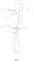
- the foam layer has a general appearance reproducing the curvature of the lumbar portion of the back of a user, said curvature comprising a concave portion extending by a convex portion having together a sinusoidal shape, said pin being placed at the junction between the concave portion and the convex portion and being able to move in translation according to an axial deflection d predetermined with respect to the wall of the structure of the seat back.
- the foam layer (2) substantially reproduces the shape of the lumbar curvature of a person, so that the back of the user rests on the entire surface of the folder, not just on a specific area of the folder. This form of the foam layer (2) thus greatly improves the comfort of the user.
- This curvature comprises a concave portion extending by a convex portion having together a sinusoidal shape.
- the coating (3) is attached to the peripheral edge of the backrest structure (1) so as to cover the foam layer (2) and is tensioned. It does not therefore naturally take the form of the curvature of the foam layer (2), and therefore does not marry the shape of the foam layer in various places.
- a device for plating the coating (3) against the foam layer (2) is thus provided at the level of the change of curvature of the backrest.
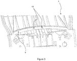
- a fixing pin (4) bears against the coating (3), passes through the foam (2) and clings into a wall (5) (see FIG. Figures 3 to 6 ) of the structure (1) of the file.
- the tip (10) is provided to snap into the wall (5) of the structure (1) of the backrest, such as a tenon. It is refined towards its end, and its sides are formed by two fins (14) made of a material capable of being elastically deformed.
- the boundary between the thickened portion (8) and the thinner intermediate portion (9) is marked by a shoulder which consists of a first stop (11).
- the boundary between the intermediate portion (9) and the tip (10) is marked by the free end of the fins (14) which projects from the intermediate portion (9), and which consists of a second stop (12).
- each rod (7) is capable of being inserted into two orifices (13) formed in a wall (5) of the structure (1) of the backrest, as illustrated in FIG. figure 3 .
- the size of each orifice (13) is slightly smaller than the wingspan (14) of the nozzle (10), and its insertion is only possible by elastic deformation of the fins (14) to the axis of the rod (7) thus allowing clipping of the tip (10).
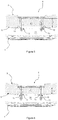
- the figure 4 illustrates the pin (4) clipped into the two orifices (13) of the wall (5) of the structure (1) of the folder. For clarity, the foam layer (2) is not visible.
- the pin (4) and clipped can freely translate according to an axial displacement (d) delimited by the two abutments (11, 12) mentioned above.
- the axial displacement (d) corresponds to the length of the intermediate portions (9) of the rods (7).
- the pin (4) is in a first clipped position, with the second stop (12) of each rod (7) in contact with the wall (5) of the structure (1) of the backrest, so as to prevent the pin ( 4) out of the orifices (13).
- the foam layer (2) is uncompressed, and the spindle (4) is in a maximum extended position.
- the distance (1) between the second stop (12) and the head (6) of the spindle (4) defines the thickness (e) of foam that can be maximum at the spindle (4).
- the foam layer (2) being elastic, it tends to exert a force on the inner face (15) of the spindle (4) towards the outside, so as to make it out to the maximum.
- the thickness of the compressed foam layer (2) must not be less than the length (s) of the extra thickness portion of the rods (7) (ie the distance between the first stop (11) and the head (6) of the spindle (4)), in which case the head (6) of the spindle (4) will protrude from the outer surface of the foam layer (2), and not only the coating (3) against the foam layer (2), but would also become a gene in the back of the user and thus cause an unpleasant sensation.
- a hollow space (16) is provided within the structure (1) of the backrest, downstream of the orifices (13) at the back of the backrest, so as to contain the portion of the rod (7) inserted into the opening (13) when the spindle (4) is in the retracted position.
- the depth of this hollow space (16) must at least correspond to the distance (p) between the first stop (11) and the end of the tip (10) of the rod (7).
- the pin (4) follows the compression movements of the foam layer (2) so as to always press the coating (3) against the foam layer ( 2) while passing unnoticed in the back of the user.
Landscapes
- Engineering & Computer Science (AREA)
- Aviation & Aerospace Engineering (AREA)
- Transportation (AREA)
- Mechanical Engineering (AREA)
- Chair Legs, Seat Parts, And Backrests (AREA)
Claims (8)
- Vorrichtung zur Befestigung/Verblendung einer Außenverkleidung (3) an einer Sitzlehne, umfassend:- eine Sitzlehnenstruktur (1) mit einer Umfangskante und einem Verbindungselement;- eine Garnitur (2), die die Struktur (1) abdeckt;- eine Verkleidung (3), die mit der Umfangskante der Struktur (1) verbunden ist und die Garnitur (2) deckt;- ein fixierstiftartiges Zwischenstück (4) mit einem äußeren Kopf (6), der auf der Verkleidung (3) aufliegt, und einer mit dem Kopf (6) integrierten Stange (7), die sich quer über die Garnitur (2) erstreckt, wobei das freie Ende der Stange (7) aus einer Düse (10) besteht, die sich im Verbindungselement derart befestigt, dass ein axialer Bewegungsbereich des Zwischenstücks im Verbindungselement erzeugt wird, wenn die Verkleidung (3) und die Garnitur (2) mit Druck beaufschlagt werden,dadurch gekennzeichnet, dass die mechanische Verbindung zwischen dem Stift (4) und der Struktur (1) einen axialen Bewegungsbereich (d) des Stifts (4) herstellt, und dass dass der axiale Bewegungsbereich (d) des Stifts (4) durch zwei Anschläge (11, 12) abgegrenzt ist, wobei der erste Anschlag (11) in der Einführungsrichtung der Stange (7) über die Schaumschicht (2) und die Struktur (1) aktiviert wird, um dessen Einführung in die Öffnung (13) zu begrenzen, wobei der zweite Anschlag (12) in der Rückzugsrichtung der Stange (7) aktiviert wird, um sie am Austreten aus der Öffnung (13) zu hindern, wobei der erste Anschlag (11) aus einer Schulter besteht, die die Grenze zwischen einem Zwischenabschnitt (9) der Stange (7) und einem überdicken Abschnitt (8) der Stange (7), die sich an den Kopf (6) des Stifts (4) anschließt, markiert, und wobei der zweite Anschlag (12) die Grenze zwischen dem Zwischenabschnitt (9) und der Düse (10) der Stange (7) markiert.
- Vorrichtung nach Anspruch 1, dadurch gekennzeichnet, dass die Garnitur (2) aus einer elastischen Verdickungsschicht (e) aus Schaum (2) besteht, die an der Struktur (1) befestigt ist, wobei die Düse (10) elastisch aufrastbar ist im Verbindungselement, das aus einer Öffnung (13) einer Wand (5) der Struktur (1) besteht, wobei die Länge (1) zwischen dem Kopf (6) des Stifts (4) und der Düse (10) derart ist, dass der Kopf (6) auf der Verkleidung (3) und gegen den Schaum (2) aufliegt.
- Vorrichtung nach dem vorstehenden Anspruch, dadurch gekennzeichnet, dass jeder Anschlag (11, 12) aus einer Oberfläche zum Blockieren der Translation des Stifts (4) besteht, die senkrecht zur Einführungsrichtung des Stifts (4) in die Öffnung (13) orientiert ist und der Wand (5) der Struktur (1), in der die Öffnung (13) ausgebildet ist, zugewandt ist, wobei die Blockierungsoberfläche geeignet ist, die Wand (5) der Struktur (1) zu kontaktieren.
- Vorrichtung nach einem der Ansprüche 2 und 3, dadurch gekennzeichnet, dass die Länge (s) des überdicken Abschnitts (8) der Stange (7) kleiner oder gleich der Stärke der Schaumschicht (2) im komprimierten Zustand ist.
- Vorrichtung nach einem der vorstehenden Ansprüche, dadurch gekennzeichnet, dass ein Hohlraum (16) in der Struktur (1) vorgesehen und der Öffnung (13) in Einführungsrichtung der Stange (7) nachgelagert ist, wobei die Tiefe des Hohlraums (16) mindestens dem Abstand (p) zwischen dem ersten Anschlag (11) und dem Ende der Düse (10) entspricht.
- Vorrichtung nach einem der vorstehenden Ansprüche, dadurch gekennzeichnet, dass die Düse (10) der Stange (7) des Stifts (4) aus einem Zapfen besteht, der sich in Richtung seines freien Endes verjüngt und periphere Blätter (14) umfasst, die geeignet sind, sich in Richtung der Achse der Stange (7) elastisch zu verformen, wenn der Zapfen in die Öffnung (13) aufrastend eingreift.
- Vorrichtung nach einem der vorstehenden Ansprüche, dadurch gekennzeichnet, dass der Stift (4) zwei identische Stangen (7) mit parallelen Bewegungsstrecken umfasst, die geeignet sind, sich in zwei Öffnungen (13) einzuführen, die in der Wand (5) der Struktur (1) ausgebildet sind.
- Verfahren nach einem der vorstehenden Ansprüche,
dadurch gekennzeichnet, dass die Schaumschicht (2) eine allgemeine Bewegungsstrecke aufweist, die die Krümmung des Lendenwirbelsäulenbereichs eines Benutzers reproduziert, wobei die Krümmung einen konkaven Teil umfasst, der sich an einen konvexen Teil anschließt, und beide zusammen eine sinusförmige Strecke bilden, und wobei der Stift (4) am Übergang zwischen dem konkaven und dem konvexen Abschnitt angeordnet ist und geeignet ist, sich relativ zur Wand (5) der Struktur (1) über eine vorgegebene axiale Strecke (d) zu verschieben.
Applications Claiming Priority (1)
| Application Number | Priority Date | Filing Date | Title |
|---|---|---|---|
| PCT/FR2012/051369 WO2013190186A1 (fr) | 2012-06-19 | 2012-06-19 | Dispositif de fixation/placage d'un revetement exterieur contre une couche de mousse fixee a une paroi de la structure d'un dossier d'un siege |
Publications (2)
| Publication Number | Publication Date |
|---|---|
| EP2861459A1 EP2861459A1 (de) | 2015-04-22 |
| EP2861459B1 true EP2861459B1 (de) | 2018-06-06 |
Family
ID=46545814
Family Applications (1)
| Application Number | Title | Priority Date | Filing Date |
|---|---|---|---|
| EP12737579.8A Not-in-force EP2861459B1 (de) | 2012-06-19 | 2012-06-19 | Vorrichtung zum fixieren/laminieren eines äusseren sitzbezuges gegen ein auf einer sitzgestellwand eines sitzkissens befestigtes schaumpolster |
Country Status (4)
| Country | Link |
|---|---|
| US (1) | US9463726B2 (de) |
| EP (1) | EP2861459B1 (de) |
| ES (1) | ES2684504T3 (de) |
| WO (1) | WO2013190186A1 (de) |
Families Citing this family (5)
| Publication number | Priority date | Publication date | Assignee | Title |
|---|---|---|---|---|
| GB202107633D0 (en) * | 2021-05-28 | 2021-07-14 | Bayerische Motoren Werke Ag | Upholstery Fixing |
| US12479143B2 (en) | 2021-12-20 | 2025-11-25 | Lear Corporation | System and method of making a mesh cushion |
| US12454111B2 (en) | 2022-05-11 | 2025-10-28 | Lear Corporation | Tool to manufacture a cushion |
| US12509343B2 (en) | 2023-02-28 | 2025-12-30 | Lear Corporation | Automated trench manufacturing and assembly for attaching trim covers to a cushion assembly |
| US20250388152A1 (en) * | 2024-06-21 | 2025-12-25 | Lear Corporation | Fastener for non-foam cushion |
Family Cites Families (15)
| Publication number | Priority date | Publication date | Assignee | Title |
|---|---|---|---|---|
| US3771199A (en) | 1972-05-24 | 1973-11-13 | C Eldringhoff | Shaft-locking-cover-clamp button assembly |
| ES236806Y (es) | 1978-06-22 | 1979-04-01 | Boton perfeccionado para tapizado de muebles. | |
| DE8120010U1 (de) * | 1980-07-18 | 1981-11-05 | Elcat D.S. - S.p.A., Torino | Vorrichtung zum steppen von polsterungen, insbesondere fuer sitze u.dgl. |
| US5214811A (en) | 1992-07-09 | 1993-06-01 | Milsco Manufacturing Company | Watertight upholstery button |
| ATE286463T1 (de) * | 2000-09-06 | 2005-01-15 | Benteler Werke Ag | Polsterung für die rückenlehne eines kraftfahrzeugsitzes |
| US20020101109A1 (en) * | 2001-01-19 | 2002-08-01 | Stiller Edwin L. | Fastener assembly for a seat |
| WO2003070509A2 (en) * | 2002-02-22 | 2003-08-28 | Woodbridge Foam Corporation | Attachment device |
| US6899399B2 (en) * | 2003-07-08 | 2005-05-31 | Lear Corporation | Attachment assembly for securing trim material to the padding of a vehicle seat |
| DE102004040400A1 (de) * | 2003-08-20 | 2005-04-21 | Woobridge Foam Corp Mississaug | Deckenbefestigungsvorrichtung |
| US6964453B1 (en) * | 2004-06-02 | 2005-11-15 | Irvin Automotive Products, Inc. | Seat trim cover assembly aid |
| US7481489B2 (en) | 2007-03-16 | 2009-01-27 | Gm Global Technology Operations, Inc. | Vehicle seat assembly |
| US8197010B2 (en) * | 2008-11-12 | 2012-06-12 | Lear Corporation | Seat trim assembly |
| JP5388775B2 (ja) | 2009-08-24 | 2014-01-15 | 株式会社ニフコ | クリップ及びシートカバー被覆構造 |
| JP5440223B2 (ja) | 2010-02-03 | 2014-03-12 | トヨタ紡織株式会社 | シートカバーの吊り込み保持構造 |
| US8191971B2 (en) * | 2010-03-17 | 2012-06-05 | Lear Corporation | Seat trim assembly |
-
2012
- 2012-06-19 EP EP12737579.8A patent/EP2861459B1/de not_active Not-in-force
- 2012-06-19 US US14/409,877 patent/US9463726B2/en not_active Expired - Fee Related
- 2012-06-19 ES ES12737579.8T patent/ES2684504T3/es active Active
- 2012-06-19 WO PCT/FR2012/051369 patent/WO2013190186A1/fr not_active Ceased
Non-Patent Citations (1)
| Title |
|---|
| None * |
Also Published As
| Publication number | Publication date |
|---|---|
| US9463726B2 (en) | 2016-10-11 |
| US20150183349A1 (en) | 2015-07-02 |
| ES2684504T3 (es) | 2018-10-03 |
| WO2013190186A1 (fr) | 2013-12-27 |
| EP2861459A1 (de) | 2015-04-22 |
Similar Documents
| Publication | Publication Date | Title |
|---|---|---|
| EP2861459B1 (de) | Vorrichtung zum fixieren/laminieren eines äusseren sitzbezuges gegen ein auf einer sitzgestellwand eines sitzkissens befestigtes schaumpolster | |
| EP2683272B1 (de) | Klappstuhl | |
| EP1213980A1 (de) | Vorrichtung zur positionsverriegelung eines bezüglich eines ortsfesten elements beweglichen teils | |
| LU81935A1 (fr) | Chaise | |
| EP0822117A1 (de) | Fahrzeugsitz mit Kopfstütze und Kopfstütze für Fahrzeugsitze | |
| EP2135129A1 (de) | Mittel zur schnellen fixierung für brillen-seitenstücke | |
| FR2881089A1 (fr) | Gaine de reception d'une d'appui-tete | |
| EP0305303A1 (de) | Sessel mit flexibler Rückenlehne | |
| EP2253248B1 (de) | Lagerungssystem für Latten die ein Endstück und ein versteifenden Element aufweisst | |
| EP3576978B1 (de) | Bezug für ein fahrzeugsitzpolster oder lehnenpolster | |
| EP2658741B1 (de) | Hilfseinrichtung zur führung einer steckzunge eines sicherheitsgurts für eine sitzerhöhung für kinder | |
| EP2028974B1 (de) | Zusammenklappbare stütze | |
| EP3021702B1 (de) | Bh mit reversibler wirkung zum näheren zusammenführen der brüste | |
| FR2884774A1 (fr) | Appui-tete pour siege de vehicule automobile | |
| FR2491312A1 (fr) | Siege a accoudoir effacable | |
| EP1043180B1 (de) | Rollo mit Handgriff und indexiertem Haken, und korrespondierendes Verfahren zur Herstellung | |
| EP4377150B1 (de) | Bezug zum abdecken eines blocks aus elastisch komprimierbarem polster zur polsterung eines kraftfahrzeugsitzes | |
| EP3400839B1 (de) | Verbesserte gelenkvorrichtung für liege- oder sitzmöbelstück | |
| FR2566757A1 (fr) | Structure de bouton decoratif pour siege de vehicule | |
| EP0008986A1 (de) | Verfahren und Vorrichtung zum Beziehen eines Polsters mit einem Bezug | |
| EP0011546B1 (de) | Stapelbare Klappmöbel | |
| FR3062351A1 (fr) | Coiffe d’habillage pour garniture d’assise ou de dossier de siege de vehicule automobile. | |
| FR2884772A1 (fr) | Coussin amovible pour siege de vehicule automobile, ensemble de siege comprenant un tel coussin, et vehicule automobile correspondants. | |
| EP2526804A1 (de) | Uhrenarmbandverschluss | |
| EP3760478A1 (de) | Kopfstütze für kraftfahrzeugsitz |
Legal Events
| Date | Code | Title | Description |
|---|---|---|---|
| PUAI | Public reference made under article 153(3) epc to a published international application that has entered the european phase |
Free format text: ORIGINAL CODE: 0009012 |
|
| 17P | Request for examination filed |
Effective date: 20150112 |
|
| AK | Designated contracting states |
Kind code of ref document: A1 Designated state(s): AL AT BE BG CH CY CZ DE DK EE ES FI FR GB GR HR HU IE IS IT LI LT LU LV MC MK MT NL NO PL PT RO RS SE SI SK SM TR |
|
| AX | Request for extension of the european patent |
Extension state: BA ME |
|
| DAX | Request for extension of the european patent (deleted) | ||
| RAP1 | Party data changed (applicant data changed or rights of an application transferred) |
Owner name: STEELCASE INC. |
|
| GRAP | Despatch of communication of intention to grant a patent |
Free format text: ORIGINAL CODE: EPIDOSNIGR1 |
|
| INTG | Intention to grant announced |
Effective date: 20180111 |
|
| GRAS | Grant fee paid |
Free format text: ORIGINAL CODE: EPIDOSNIGR3 |
|
| GRAA | (expected) grant |
Free format text: ORIGINAL CODE: 0009210 |
|
| AK | Designated contracting states |
Kind code of ref document: B1 Designated state(s): AL AT BE BG CH CY CZ DE DK EE ES FI FR GB GR HR HU IE IS IT LI LT LU LV MC MK MT NL NO PL PT RO RS SE SI SK SM TR |
|
| REG | Reference to a national code |
Ref country code: GB Ref legal event code: FG4D Free format text: NOT ENGLISH |
|
| REG | Reference to a national code |
Ref country code: CH Ref legal event code: EP Ref country code: AT Ref legal event code: REF Ref document number: 1005709 Country of ref document: AT Kind code of ref document: T Effective date: 20180615 |
|
| REG | Reference to a national code |
Ref country code: FR Ref legal event code: PLFP Year of fee payment: 7 |
|
| REG | Reference to a national code |
Ref country code: IE Ref legal event code: FG4D Free format text: LANGUAGE OF EP DOCUMENT: FRENCH |
|
| REG | Reference to a national code |
Ref country code: DE Ref legal event code: R096 Ref document number: 602012047167 Country of ref document: DE |
|
| PGFP | Annual fee paid to national office [announced via postgrant information from national office to epo] |
Ref country code: FR Payment date: 20180626 Year of fee payment: 7 |
|
| REG | Reference to a national code |
Ref country code: ES Ref legal event code: FG2A Ref document number: 2684504 Country of ref document: ES Kind code of ref document: T3 Effective date: 20181003 |
|
| REG | Reference to a national code |
Ref country code: NL Ref legal event code: MP Effective date: 20180606 |
|
| REG | Reference to a national code |
Ref country code: LT Ref legal event code: MG4D |
|
| PG25 | Lapsed in a contracting state [announced via postgrant information from national office to epo] |
Ref country code: SE Free format text: LAPSE BECAUSE OF FAILURE TO SUBMIT A TRANSLATION OF THE DESCRIPTION OR TO PAY THE FEE WITHIN THE PRESCRIBED TIME-LIMIT Effective date: 20180606 Ref country code: CY Free format text: LAPSE BECAUSE OF FAILURE TO SUBMIT A TRANSLATION OF THE DESCRIPTION OR TO PAY THE FEE WITHIN THE PRESCRIBED TIME-LIMIT Effective date: 20180606 Ref country code: LT Free format text: LAPSE BECAUSE OF FAILURE TO SUBMIT A TRANSLATION OF THE DESCRIPTION OR TO PAY THE FEE WITHIN THE PRESCRIBED TIME-LIMIT Effective date: 20180606 Ref country code: FI Free format text: LAPSE BECAUSE OF FAILURE TO SUBMIT A TRANSLATION OF THE DESCRIPTION OR TO PAY THE FEE WITHIN THE PRESCRIBED TIME-LIMIT Effective date: 20180606 Ref country code: NO Free format text: LAPSE BECAUSE OF FAILURE TO SUBMIT A TRANSLATION OF THE DESCRIPTION OR TO PAY THE FEE WITHIN THE PRESCRIBED TIME-LIMIT Effective date: 20180906 Ref country code: BG Free format text: LAPSE BECAUSE OF FAILURE TO SUBMIT A TRANSLATION OF THE DESCRIPTION OR TO PAY THE FEE WITHIN THE PRESCRIBED TIME-LIMIT Effective date: 20180906 |
|
| PGFP | Annual fee paid to national office [announced via postgrant information from national office to epo] |
Ref country code: GB Payment date: 20180627 Year of fee payment: 7 Ref country code: ES Payment date: 20180702 Year of fee payment: 7 Ref country code: DE Payment date: 20180627 Year of fee payment: 7 |
|
| PG25 | Lapsed in a contracting state [announced via postgrant information from national office to epo] |
Ref country code: LV Free format text: LAPSE BECAUSE OF FAILURE TO SUBMIT A TRANSLATION OF THE DESCRIPTION OR TO PAY THE FEE WITHIN THE PRESCRIBED TIME-LIMIT Effective date: 20180606 Ref country code: RS Free format text: LAPSE BECAUSE OF FAILURE TO SUBMIT A TRANSLATION OF THE DESCRIPTION OR TO PAY THE FEE WITHIN THE PRESCRIBED TIME-LIMIT Effective date: 20180606 Ref country code: HR Free format text: LAPSE BECAUSE OF FAILURE TO SUBMIT A TRANSLATION OF THE DESCRIPTION OR TO PAY THE FEE WITHIN THE PRESCRIBED TIME-LIMIT Effective date: 20180606 Ref country code: GR Free format text: LAPSE BECAUSE OF FAILURE TO SUBMIT A TRANSLATION OF THE DESCRIPTION OR TO PAY THE FEE WITHIN THE PRESCRIBED TIME-LIMIT Effective date: 20180907 |
|
| REG | Reference to a national code |
Ref country code: AT Ref legal event code: MK05 Ref document number: 1005709 Country of ref document: AT Kind code of ref document: T Effective date: 20180606 |
|
| PG25 | Lapsed in a contracting state [announced via postgrant information from national office to epo] |
Ref country code: NL Free format text: LAPSE BECAUSE OF FAILURE TO SUBMIT A TRANSLATION OF THE DESCRIPTION OR TO PAY THE FEE WITHIN THE PRESCRIBED TIME-LIMIT Effective date: 20180606 |
|
| PG25 | Lapsed in a contracting state [announced via postgrant information from national office to epo] |
Ref country code: PL Free format text: LAPSE BECAUSE OF FAILURE TO SUBMIT A TRANSLATION OF THE DESCRIPTION OR TO PAY THE FEE WITHIN THE PRESCRIBED TIME-LIMIT Effective date: 20180606 Ref country code: SK Free format text: LAPSE BECAUSE OF FAILURE TO SUBMIT A TRANSLATION OF THE DESCRIPTION OR TO PAY THE FEE WITHIN THE PRESCRIBED TIME-LIMIT Effective date: 20180606 Ref country code: CZ Free format text: LAPSE BECAUSE OF FAILURE TO SUBMIT A TRANSLATION OF THE DESCRIPTION OR TO PAY THE FEE WITHIN THE PRESCRIBED TIME-LIMIT Effective date: 20180606 Ref country code: EE Free format text: LAPSE BECAUSE OF FAILURE TO SUBMIT A TRANSLATION OF THE DESCRIPTION OR TO PAY THE FEE WITHIN THE PRESCRIBED TIME-LIMIT Effective date: 20180606 Ref country code: IS Free format text: LAPSE BECAUSE OF FAILURE TO SUBMIT A TRANSLATION OF THE DESCRIPTION OR TO PAY THE FEE WITHIN THE PRESCRIBED TIME-LIMIT Effective date: 20181006 Ref country code: AT Free format text: LAPSE BECAUSE OF FAILURE TO SUBMIT A TRANSLATION OF THE DESCRIPTION OR TO PAY THE FEE WITHIN THE PRESCRIBED TIME-LIMIT Effective date: 20180606 Ref country code: RO Free format text: LAPSE BECAUSE OF FAILURE TO SUBMIT A TRANSLATION OF THE DESCRIPTION OR TO PAY THE FEE WITHIN THE PRESCRIBED TIME-LIMIT Effective date: 20180606 |
|
| REG | Reference to a national code |
Ref country code: CH Ref legal event code: PL |
|
| PG25 | Lapsed in a contracting state [announced via postgrant information from national office to epo] |
Ref country code: SM Free format text: LAPSE BECAUSE OF FAILURE TO SUBMIT A TRANSLATION OF THE DESCRIPTION OR TO PAY THE FEE WITHIN THE PRESCRIBED TIME-LIMIT Effective date: 20180606 Ref country code: IT Free format text: LAPSE BECAUSE OF FAILURE TO SUBMIT A TRANSLATION OF THE DESCRIPTION OR TO PAY THE FEE WITHIN THE PRESCRIBED TIME-LIMIT Effective date: 20180606 |
|
| REG | Reference to a national code |
Ref country code: BE Ref legal event code: MM Effective date: 20180630 |
|
| REG | Reference to a national code |
Ref country code: DE Ref legal event code: R097 Ref document number: 602012047167 Country of ref document: DE |
|
| REG | Reference to a national code |
Ref country code: IE Ref legal event code: MM4A |
|
| PG25 | Lapsed in a contracting state [announced via postgrant information from national office to epo] |
Ref country code: LU Free format text: LAPSE BECAUSE OF NON-PAYMENT OF DUE FEES Effective date: 20180619 Ref country code: MC Free format text: LAPSE BECAUSE OF FAILURE TO SUBMIT A TRANSLATION OF THE DESCRIPTION OR TO PAY THE FEE WITHIN THE PRESCRIBED TIME-LIMIT Effective date: 20180606 |
|
| PLBE | No opposition filed within time limit |
Free format text: ORIGINAL CODE: 0009261 |
|
| STAA | Information on the status of an ep patent application or granted ep patent |
Free format text: STATUS: NO OPPOSITION FILED WITHIN TIME LIMIT |
|
| PG25 | Lapsed in a contracting state [announced via postgrant information from national office to epo] |
Ref country code: CH Free format text: LAPSE BECAUSE OF NON-PAYMENT OF DUE FEES Effective date: 20180630 Ref country code: LI Free format text: LAPSE BECAUSE OF NON-PAYMENT OF DUE FEES Effective date: 20180630 Ref country code: IE Free format text: LAPSE BECAUSE OF NON-PAYMENT OF DUE FEES Effective date: 20180619 |
|
| 26N | No opposition filed |
Effective date: 20190307 |
|
| PG25 | Lapsed in a contracting state [announced via postgrant information from national office to epo] |
Ref country code: SI Free format text: LAPSE BECAUSE OF FAILURE TO SUBMIT A TRANSLATION OF THE DESCRIPTION OR TO PAY THE FEE WITHIN THE PRESCRIBED TIME-LIMIT Effective date: 20180606 Ref country code: BE Free format text: LAPSE BECAUSE OF NON-PAYMENT OF DUE FEES Effective date: 20180630 Ref country code: DK Free format text: LAPSE BECAUSE OF FAILURE TO SUBMIT A TRANSLATION OF THE DESCRIPTION OR TO PAY THE FEE WITHIN THE PRESCRIBED TIME-LIMIT Effective date: 20180606 |
|
| PG25 | Lapsed in a contracting state [announced via postgrant information from national office to epo] |
Ref country code: AL Free format text: LAPSE BECAUSE OF FAILURE TO SUBMIT A TRANSLATION OF THE DESCRIPTION OR TO PAY THE FEE WITHIN THE PRESCRIBED TIME-LIMIT Effective date: 20180606 |
|
| REG | Reference to a national code |
Ref country code: DE Ref legal event code: R119 Ref document number: 602012047167 Country of ref document: DE |
|
| PG25 | Lapsed in a contracting state [announced via postgrant information from national office to epo] |
Ref country code: MT Free format text: LAPSE BECAUSE OF FAILURE TO SUBMIT A TRANSLATION OF THE DESCRIPTION OR TO PAY THE FEE WITHIN THE PRESCRIBED TIME-LIMIT Effective date: 20180606 |
|
| GBPC | Gb: european patent ceased through non-payment of renewal fee |
Effective date: 20190619 |
|
| PG25 | Lapsed in a contracting state [announced via postgrant information from national office to epo] |
Ref country code: TR Free format text: LAPSE BECAUSE OF FAILURE TO SUBMIT A TRANSLATION OF THE DESCRIPTION OR TO PAY THE FEE WITHIN THE PRESCRIBED TIME-LIMIT Effective date: 20180606 |
|
| PG25 | Lapsed in a contracting state [announced via postgrant information from national office to epo] |
Ref country code: GB Free format text: LAPSE BECAUSE OF NON-PAYMENT OF DUE FEES Effective date: 20190619 Ref country code: DE Free format text: LAPSE BECAUSE OF NON-PAYMENT OF DUE FEES Effective date: 20200101 |
|
| PG25 | Lapsed in a contracting state [announced via postgrant information from national office to epo] |
Ref country code: PT Free format text: LAPSE BECAUSE OF FAILURE TO SUBMIT A TRANSLATION OF THE DESCRIPTION OR TO PAY THE FEE WITHIN THE PRESCRIBED TIME-LIMIT Effective date: 20180606 |
|
| PG25 | Lapsed in a contracting state [announced via postgrant information from national office to epo] |
Ref country code: FR Free format text: LAPSE BECAUSE OF NON-PAYMENT OF DUE FEES Effective date: 20190630 Ref country code: HU Free format text: LAPSE BECAUSE OF FAILURE TO SUBMIT A TRANSLATION OF THE DESCRIPTION OR TO PAY THE FEE WITHIN THE PRESCRIBED TIME-LIMIT; INVALID AB INITIO Effective date: 20120619 Ref country code: MK Free format text: LAPSE BECAUSE OF NON-PAYMENT OF DUE FEES Effective date: 20180606 |
|
| REG | Reference to a national code |
Ref country code: ES Ref legal event code: FD2A Effective date: 20201028 |
|
| PG25 | Lapsed in a contracting state [announced via postgrant information from national office to epo] |
Ref country code: ES Free format text: LAPSE BECAUSE OF NON-PAYMENT OF DUE FEES Effective date: 20190620 |