EP2861315B1 - Evaporation device for reducing wall-effects - Google Patents
Evaporation device for reducing wall-effects Download PDFInfo
- Publication number
- EP2861315B1 EP2861315B1 EP13744823.9A EP13744823A EP2861315B1 EP 2861315 B1 EP2861315 B1 EP 2861315B1 EP 13744823 A EP13744823 A EP 13744823A EP 2861315 B1 EP2861315 B1 EP 2861315B1
- Authority
- EP
- European Patent Office
- Prior art keywords
- liquid
- meniscus
- container
- steam
- substances
- Prior art date
- Legal status (The legal status is an assumption and is not a legal conclusion. Google has not performed a legal analysis and makes no representation as to the accuracy of the status listed.)
- Not-in-force
Links
- 238000001704 evaporation Methods 0.000 title claims description 32
- 230000008020 evaporation Effects 0.000 title claims description 30
- 230000000694 effects Effects 0.000 title description 6
- 239000007788 liquid Substances 0.000 claims description 150
- 239000000126 substance Substances 0.000 claims description 91
- 230000005499 meniscus Effects 0.000 claims description 81
- 238000010438 heat treatment Methods 0.000 claims description 13
- 238000001816 cooling Methods 0.000 claims description 5
- 230000000630 rising effect Effects 0.000 claims description 4
- 230000000717 retained effect Effects 0.000 claims description 2
- 239000007787 solid Substances 0.000 description 71
- 238000000034 method Methods 0.000 description 25
- 238000009835 boiling Methods 0.000 description 13
- 239000002245 particle Substances 0.000 description 12
- 230000008021 deposition Effects 0.000 description 8
- 239000000463 material Substances 0.000 description 8
- 230000033001 locomotion Effects 0.000 description 6
- 230000002093 peripheral effect Effects 0.000 description 5
- 238000000926 separation method Methods 0.000 description 5
- 238000006243 chemical reaction Methods 0.000 description 4
- 230000008569 process Effects 0.000 description 4
- 230000015572 biosynthetic process Effects 0.000 description 3
- 239000006185 dispersion Substances 0.000 description 2
- 239000007789 gas Substances 0.000 description 2
- 238000005259 measurement Methods 0.000 description 2
- 230000008018 melting Effects 0.000 description 2
- 238000002844 melting Methods 0.000 description 2
- 239000002244 precipitate Substances 0.000 description 2
- 238000012795 verification Methods 0.000 description 2
- 238000010521 absorption reaction Methods 0.000 description 1
- 230000001464 adherent effect Effects 0.000 description 1
- 238000005054 agglomeration Methods 0.000 description 1
- 230000002776 aggregation Effects 0.000 description 1
- 239000003153 chemical reaction reagent Substances 0.000 description 1
- 238000004140 cleaning Methods 0.000 description 1
- 230000005494 condensation Effects 0.000 description 1
- 238000009833 condensation Methods 0.000 description 1
- 238000010411 cooking Methods 0.000 description 1
- 230000003247 decreasing effect Effects 0.000 description 1
- 239000000839 emulsion Substances 0.000 description 1
- 239000010408 film Substances 0.000 description 1
- 239000012530 fluid Substances 0.000 description 1
- 239000003205 fragrance Substances 0.000 description 1
- 230000006870 function Effects 0.000 description 1
- 239000007792 gaseous phase Substances 0.000 description 1
- 239000012456 homogeneous solution Substances 0.000 description 1
- 230000003993 interaction Effects 0.000 description 1
- 239000007791 liquid phase Substances 0.000 description 1
- 239000012071 phase Substances 0.000 description 1
- 230000001737 promoting effect Effects 0.000 description 1
- 230000035807 sensation Effects 0.000 description 1
- 239000007921 spray Substances 0.000 description 1
- 239000010409 thin film Substances 0.000 description 1
- 238000002604 ultrasonography Methods 0.000 description 1
- XLYOFNOQVPJJNP-UHFFFAOYSA-N water Substances O XLYOFNOQVPJJNP-UHFFFAOYSA-N 0.000 description 1
Images

Classifications
-
- B—PERFORMING OPERATIONS; TRANSPORTING
- B01—PHYSICAL OR CHEMICAL PROCESSES OR APPARATUS IN GENERAL
- B01D—SEPARATION
- B01D3/00—Distillation or related exchange processes in which liquids are contacted with gaseous media, e.g. stripping
- B01D3/02—Distillation or related exchange processes in which liquids are contacted with gaseous media, e.g. stripping in boilers or stills
-
- B—PERFORMING OPERATIONS; TRANSPORTING
- B01—PHYSICAL OR CHEMICAL PROCESSES OR APPARATUS IN GENERAL
- B01D—SEPARATION
- B01D5/00—Condensation of vapours; Recovering volatile solvents by condensation
- B01D5/0057—Condensation of vapours; Recovering volatile solvents by condensation in combination with other processes
- B01D5/006—Condensation of vapours; Recovering volatile solvents by condensation in combination with other processes with evaporation or distillation
- B01D5/0066—Dome shaped condensation
-
- B—PERFORMING OPERATIONS; TRANSPORTING
- B01—PHYSICAL OR CHEMICAL PROCESSES OR APPARATUS IN GENERAL
- B01J—CHEMICAL OR PHYSICAL PROCESSES, e.g. CATALYSIS OR COLLOID CHEMISTRY; THEIR RELEVANT APPARATUS
- B01J14/00—Chemical processes in general for reacting liquids with liquids; Apparatus specially adapted therefor
-
- B—PERFORMING OPERATIONS; TRANSPORTING
- B01—PHYSICAL OR CHEMICAL PROCESSES OR APPARATUS IN GENERAL
- B01J—CHEMICAL OR PHYSICAL PROCESSES, e.g. CATALYSIS OR COLLOID CHEMISTRY; THEIR RELEVANT APPARATUS
- B01J19/00—Chemical, physical or physico-chemical processes in general; Their relevant apparatus
- B01J19/0053—Details of the reactor
- B01J19/006—Baffles
-
- B—PERFORMING OPERATIONS; TRANSPORTING
- B01—PHYSICAL OR CHEMICAL PROCESSES OR APPARATUS IN GENERAL
- B01J—CHEMICAL OR PHYSICAL PROCESSES, e.g. CATALYSIS OR COLLOID CHEMISTRY; THEIR RELEVANT APPARATUS
- B01J19/00—Chemical, physical or physico-chemical processes in general; Their relevant apparatus
- B01J19/18—Stationary reactors having moving elements inside
-
- B—PERFORMING OPERATIONS; TRANSPORTING
- B01—PHYSICAL OR CHEMICAL PROCESSES OR APPARATUS IN GENERAL
- B01J—CHEMICAL OR PHYSICAL PROCESSES, e.g. CATALYSIS OR COLLOID CHEMISTRY; THEIR RELEVANT APPARATUS
- B01J19/00—Chemical, physical or physico-chemical processes in general; Their relevant apparatus
- B01J19/24—Stationary reactors without moving elements inside
-
- B—PERFORMING OPERATIONS; TRANSPORTING
- B01—PHYSICAL OR CHEMICAL PROCESSES OR APPARATUS IN GENERAL
- B01J—CHEMICAL OR PHYSICAL PROCESSES, e.g. CATALYSIS OR COLLOID CHEMISTRY; THEIR RELEVANT APPARATUS
- B01J2219/00—Chemical, physical or physico-chemical processes in general; Their relevant apparatus
- B01J2219/00049—Controlling or regulating processes
- B01J2219/00051—Controlling the temperature
- B01J2219/00132—Controlling the temperature using electric heating or cooling elements
- B01J2219/00135—Electric resistance heaters
-
- B—PERFORMING OPERATIONS; TRANSPORTING
- B01—PHYSICAL OR CHEMICAL PROCESSES OR APPARATUS IN GENERAL
- B01J—CHEMICAL OR PHYSICAL PROCESSES, e.g. CATALYSIS OR COLLOID CHEMISTRY; THEIR RELEVANT APPARATUS
- B01J2219/00—Chemical, physical or physico-chemical processes in general; Their relevant apparatus
- B01J2219/00761—Details of the reactor
- B01J2219/00763—Baffles
- B01J2219/00765—Baffles attached to the reactor wall
- B01J2219/00768—Baffles attached to the reactor wall vertical
-
- B—PERFORMING OPERATIONS; TRANSPORTING
- B01—PHYSICAL OR CHEMICAL PROCESSES OR APPARATUS IN GENERAL
- B01J—CHEMICAL OR PHYSICAL PROCESSES, e.g. CATALYSIS OR COLLOID CHEMISTRY; THEIR RELEVANT APPARATUS
- B01J2219/00—Chemical, physical or physico-chemical processes in general; Their relevant apparatus
- B01J2219/00761—Details of the reactor
- B01J2219/00763—Baffles
- B01J2219/00765—Baffles attached to the reactor wall
- B01J2219/0077—Baffles attached to the reactor wall inclined
-
- B—PERFORMING OPERATIONS; TRANSPORTING
- B01—PHYSICAL OR CHEMICAL PROCESSES OR APPARATUS IN GENERAL
- B01J—CHEMICAL OR PHYSICAL PROCESSES, e.g. CATALYSIS OR COLLOID CHEMISTRY; THEIR RELEVANT APPARATUS
- B01J2219/00—Chemical, physical or physico-chemical processes in general; Their relevant apparatus
- B01J2219/19—Details relating to the geometry of the reactor
- B01J2219/194—Details relating to the geometry of the reactor round
- B01J2219/1941—Details relating to the geometry of the reactor round circular or disk-shaped
- B01J2219/1946—Details relating to the geometry of the reactor round circular or disk-shaped conical
Definitions
- the present invention relates to methods for controlling substances present in a liquid and their applications.
- the present invention relates to an equipment for separating at least one substance present in a liquid, which is an application of these methods.
- Control of the substances means activities aimed at reducing or maintaining constant or increasing these substances according to the well-known and broad meaning that is given to the word “control” in the “engineering” field; therefore "control of the substances” as used herein, means neither the simple verification of which substances are present nor simply the simple measurement of the amount of substances present:
- Patent document US3507753 discloses an equipment for separating at least one substance present in a liquid.
- the steam originating from the meniscus close to the walls of the container
- the steam originating from the flat surface of the liquid and the steam originating from the steam bubbles rising in the liquid. Therefore, such equipment needs to be improved in order to take into account the above mentioned technical considerations of the inventors.
- the present patent application describes and claims one specific and advantageous equipment for separating at least one substance present in a liquid.
- the inventor aimed at providing control methods of broad application both as regards the liquid and as regards the substances.
- the inventor focused on solid substances in particular, i.e., which are present in the liquid in the form of very small, small or medium sized solid particles; large and heavy solid particles tend to naturally precipitate.
- the methods according to the present invention are also useful in other situations.
- the present invention can be understood with a good technical and scientific knowledge of the evaporation, ebullition, the Marangoni effect, menisci and capillarity, friction and adhesion between liquids and solids, and, of course, of physics, fluid dynamics, thermodynamics and basic chemistry; such knowledge is assumed to be known in the detailed description which follows.
- Fig. 1 shows a container 101 that contains a mass of liquid 102 in which substances (not visible in the figure) are present; the container has a cylindrical symmetry, and, in particular, looks like a pot with a lid.
- heating means 103 adapted to heat the liquid 102; in this figure, the heating means 103 are adjacent to the bottom (in particular this is a flat bottom) of the container 101, are centrally positioned and can be constituted, for example, by an electrical resistor; the heating means 103 heat the bottom of the container 101 and, by conduction, the liquid mass 102; as is known, this heating causes evaporation of the liquid 102 and, if the temperature rises sufficiently, boiling of the liquid 102.
- the upper part of the container 101 is dome-shaped and has an opening 105 from which the generator steam can escape due to the heating.
- This figure shows a concave meniscus (the dimensions thereof have been deliberately exaggerated in this figure), which has formed internally, at a certain height, at all the side wall of the container 101 (which is thus its perimeter wall); in a central zone 106 (which is, in particular, a circle), the free surface of the liquid 102 (which is located in the upper part) is perfectly flat; in a peripheral zone 107 (which is, in particular, a circular crown) the free surface of the liquid 102 (which is located in the upper part and which includes the meniscus) is curved upwards - this peripheral zone could be deemed, for example, a few millimetres wide; a thin layer of liquid in the central zone 106, below the upper free surface, can be deemed free of other substances and this is schematically represented by the horizontal dotted line in this figure.
- This figure schematically shows the flow of matter in the liquid phase from the lower central zone of the container 101 to the upper peripheral zone (where the meniscus is) of the container 101, as well as the flow of matter in the gaseous phase from the upper free surface of the liquid 102 to the opening 105; as will be better explained below, there is greater evaporation from the free surface in the peripheral zone 107, i.e. from the meniscus, with respect to the central region 106.
- the equipment shown in Fig. 1 can be used to provide methods for controlling substances present in a liquid according to the present invention.
- the liquid mass (in which other substances are present) is brought to temperature and pressure conditions such as to give rise to an appreciable evaporation of the liquid and at least one solid surface is arranged, in part inside said liquid mass and in part outside said liquid mass so as to establish one (or more) appreciable meniscus of the liquid on this solid surface; in the particular case of Fig. 1 , the solid surface is constituted by the inner surface of the side wall of the container 101, which is vertical, but which could also be oblique.
- appreciable evaporation means, for example, that 5-25%, preferably 10-20%, of the liquid mass contained in the treatment container evaporates in one hour; alternatively, for example, we can refer to the temperature (the average temperature, for example) of the liquid mass and ensure that this is higher than the boiling temperature of the liquid reduced by 60°C, preferably ensure that this is higher than the boiling temperature of the liquid reduced by 40°C, more preferably ensue that this is higher than the boiling temperature of the liquid reduced by 20°C.
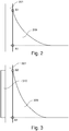
- “appreciable meniscus” means, for example, that the liquid rises, close to the solid surface, by least 2mm, preferably by at least 4mm, more preferably by at least 6mm - in Fig. 2 the rise corresponds to the difference between the height B1 and the height A1 and in Fig. 3 the rise corresponds to the difference between the height B2 and the height A2.
- One of the fundamental elements (probably the most important) of the method for controlling the substances is the controlling of the shape and/or of the size and/or of the extension and/or of the position and/or of the temperature of the meniscus (or of the menisci, in the event of there being more than one) so as to control the evaporation of the liquid through the meniscus;
- the meniscus can be concave or convex and more or less arched;
- the meniscus can be more or less high;
- the meniscus can be more or less long;
- the meniscus can be stable or movable, and variously arranged in relation to the parts of the treatment equipment;
- the meniscus can be more or less hot; it is of course understood that there are many implementation possibilities.
- Control of shape, size, extension, position, temperature of the meniscus as used herein means the activities that aim to reduce or maintain constant or increase these magnitudes, according to the well-known and broad meaning that is given to the word “control” in the “engineering” field; therefore "control of " as used herein means neither simply the verification nor simply the measurement of these magnitudes.
- a region of (concave) meniscus is divided into three sub-regions: a lower sub-region of intrinsic meniscus, above this a sub-region having a thin evaporating film and, above this still, a sub-region having a thin film adsorbed by the solid, non-evaporating surface; when representing the meniscus the uppermost sub-region is usually disregarded.
- the solid surface used to create the meniscus can correspond to the inner surface of the perimeter wall of a container containing the liquid, as in the case of the equipment of Fig. 1 .
- the solid surface or the solid surfaces are distinct from the surfaces of the walls of the container at least at the free surface of the liquid.
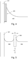
- the solid surface can be movable as shown in Fig. 4 and Fig. 5 (in both figures the menisci have deliberately exaggerated dimensions); in Fig. 4 , the solid surface 408 has layers that can be removed, in particular entrained upwards; in Fig. 5 , the solid surface 508 can move both vertically (arrow V), repeatedly up and down in particular, and horizontally (arrow H), repeatedly to the left and right in particular near the perimeter wall of the container 501.
- the solid surface can be repeatedly inserted into and extracted from the liquid. This can be obtained, for example, by means of a rotary movement: if the solid surface is a circle arranged with axis parallel to the surface of the liquid there is a continuous exchange of the surface in contact with the liquid when the circle rotates.
- the solid movable surface can be heated to influence the deposition of material.
- the solid movable surface can be cleaned (of deposits of substance/s) before being reinserted into the liquid.
- the solid surface can be repeatedly moved closer to and away from the perimeter wall of a container containing the liquid, as shown by the arrow H in Fig. 5 in relation to the surface 508 and to the perimeter wall of the container 501; thus, the menisci bend more and wet the upper parts of the surface and of the wall. Also in this case, the solid surface and/or the perimeter wall can be heated to influence the deposition of the material. Also in this case, the solid surface and/or the perimeter wall can be cleaned repeatedly.
- the solid surface used to create the meniscus or the menisci can be removable; for example, it can be removed when the deposits of the substance/s exceed a certain level or thickness; this removal can be total or partial, for example, of just an outer layer of the solid surface (i.e. the one in contact with the liquid, in particular with the zone of the meniscus).
- Fig. 4 shows a solid surface 408 adjacent to the perimeter wall of the container 401 constituted by a plurality of thin layers that are adjacent to each other and that can slide between them; thus, when the deposits of the substance/s exceed a certain level or thickness, the outermost layer (i.e. the one in contact with the liquid, in particular with the zone of the meniscus) can be removed, in particular entrained upwards, and a new layer remains in contact with the liquid 402.
- the solid surface can be cleaned of substances deposited thereon by means of sliding; this sliding can be obtained by means of one or more members adjacent to the solid surface and moved by means of movement means (using magnetic forces in particular); this sliding can be obtained by means of floating and freely movable members on the free surface of the liquid.
- the solid surface can be cleaned by substances deposited thereon by ultrasound.
- the phenomena which occur in the meniscus region are influenced by the temperature of the solid surface used to create the meniscus; therefore, depending on the use of the control method, it can be useful to heat or cool this meniscus region; the most direct method of influencing this temperature is the method of controlling the temperature of the solid surface - reference can be made to Fig. 2 , which shows in detail a meniscus 209 adjacent to a portion of the side wall of the container 201.
- This control is particularly important when the solid surface corresponds to a wall of the container; indeed, if the container is heated to obtain the evaporation of the liquid (as in Fig. 1 ), part of this heat is transmitted to the meniscus region by conduction.
- Fig. 2 there is no particular stratagem for controlling the temperature of the wall of the container 201, and the meniscus 209 takes on a certain shape and a certain extension, i.e. it begins at the height A1 (considering the level of the liquid in the container) and ends (substantially) at the height B1.
- Fig. 3 on the outer side of the wall of the container 301, are positioned means 310 which cool the wall itself and thus the adjacent meniscus 309; it is observed that the meniscus 309 takes on a different shape and a different extension, i.e. it begins at the height A2 (considering the level of the liquid in the container) and ends (substantially) at the height B2 greater than the height B; the solid surface is thus kept wetter and thus reducing the likelihood of the solid particles deposited therein from detaching therefrom and being entrained by the steam; in addition, if the meniscus is cold, evaporation is reduced and the likelihood of bubbles of steam forming therein is further reduced. It is worth clarifying that in Fig.
- the means 310 are perfectly aligned with the heights A2 and B2, but this is not indispensable; on the contrary, they should extend a little below the height A2 and a little above the height B2; in addition, the means 310 should take into account the level of liquid in the container, should this not be constant during the treatment period.
- the various possible solutions can be divided into two categories: the active solutions, which are associated with or integrated in the wall and which introduce or remove heat in a zone horizontally aligned with the meniscus or in a zone that is a little lower and/or a little higher, and the passive solutions, which are associated with or integrated in the wall and which promote or hinder the flow of heat along the wall.
- the temperature of the wall of the container is also influenced by the introduction of heat due to the convective motions of the liquid towards the zone of the meniscus and to the absorption of heat due to evaporation in the zone of the meniscus.
- Control of the substances present in the liquid can also be obtained by controlling the level of the liquid in the container; indeed, so long as they remain wet and stable, any deposits on the solid surface/s do not greatly contribute to the entrainment by the nascent steam. Therefore, is very advantageous to maintain constant the level of the liquid in the container to limit the detachment of small or very small solid particles from solid surfaces; it is also possible to increase perhaps slowly, the level of liquid in the container until the container is full. For these applications it is advantageous (even if not strictly necessary) to record the level of the liquid by measuring the pressure at the bottom of the container; thus, the recording is continuous and accurate.
- the introduction of liquid into the container can be envisaged; preferably, this introduction occurs slowly at the bottom of the container so as not to disturb the surface regions of the liquid (with turbulence or vortices caused by the inflow), either at the centre or on the perimeter of the container, in particular not where there are menisci.
- the liquid must be heated to cause the evaporation thereof.
- a first possibility is to bring the liquid to its boiling temperature; the evaporation is thus very strong; however, it should be ensured that the bubbles of steam are not too large i.e. that the boiling is not violent.
- the liquid can be heated to below the boiling temperature, for example to a temperature ranging between 70% and 99% of the boiling temperature thereof (expressed in degrees Celsius), or, more advantageously, to a temperature between 80% and 90% of the boiling temperature thereof (expressed in degrees Celsius).
- any bubbles of steam it is advantageous for the heat source to be in the central region so that the convective motions of hot liquid with any bubbles of steam do not rise at the perimeter walls of the container (or of the solid surfaces adapted to create menisci) and do not reach the meniscus or menisci and are not at risk of detaching particles of solid substances from the deposits on the perimeter walls of the container (or on solid surfaces adapted to create menisci); it must be taken into account that these deposits can be more or less adherent (this depends, in particular, on the material and on the properties of the wall) and more or less compact (this depends, in particular, on the substance that forms the deposit).
- the perimeter walls (vertical or oblique) of the container are cooled in order to prevent the risk of the walls themselves being a source of convective motions and of bubbles of steam.
- the present invention can provide for controlling of the flow due to evaporation of the liquid through said meniscus; according to the observations of the inventor, this flow is typically rich in substances other than the liquid itself.
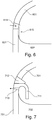
- the wall of the container 701 internally has, at the concave meniscus of the liquid 702, above the same, a flange 711 (preferably) bent downwards; above the flange there can advantageously be cooling means 712, adapted to cool the flange 711 (they also indirectly cool the wall of the container 701, both downwards and upwards); when the steam rises upwards from the meniscus, it is retained by the flange 711, which is cold and condenses returning it towards the liquid below.
- cooling means 712 adapted to cool the flange 711 (they also indirectly cool the wall of the container 701, both downwards and upwards); when the steam rises upwards from the meniscus, it is retained by the flange 711, which is cold and condenses returning it towards the liquid below.
- the flow of steam can be removed from the container.
- Fig. 7 there is an opening 713 just below the flange 711 which can be connected to a removal duct; following removal, the steam can be condensed (by cooling for example) away from the container 701.
- the shape and the size of the flange can differ from the one shown in Fig. 7 ; the flange protrudes towards the inside of the container preferably by at least 5mm, more preferably by at least 10mm, more preferably still by at least 15mm.
- the cooling means if present, could be associated with a flange of extremely small, even null size; in particular, the shape and the upper extension of the container 701 could act as a flange; the function of the cooling means is to promote condensation of the steam originating from the meniscus.
- a flange equal to or similar to the member 711 can be defined as a "skirt”, and in particular a “cooled skirt”. This skirt is located near the meniscus, i.e. near the solid surface that generates it. There could be multiple skirts, one for each meniscus. The skirt could also be movable and thus follow the movements (raising or lowering) of the level of liquid in the container.
- the steam originating from the meniscus can be kept separate, by means of the skirt, from the steam originating from the flat surface of the liquid and from the steam originating from the rising bubbles of steam; discrimination can therefore take place on the basis of the ,steam content of these three sources.
- the present invention can provide for a thin layer of liquid (which, according to the observations of the inventor, is extremely pure and free of substances) to be removed form the free (upper) surface of the liquid, excluding the free surface of the meniscus.
- This removal can be obtained, for example, by heating the liquid so as to give rise to an appreciable evaporation by radiant heating means, and by placing these heating means so as to irradiate the free (upper) surface of the liquid and not to irradiate the meniscus or menisci.
- this removal can be performed, for example, by mechanical means, in particular by maintaining the level of the liquid slightly higher at the edge of the perimeter wall of the container containing the liquid itself.
- the present invention can provide for the solid surface used to create the meniscus or menisci to be wet, in particular maintained wet, above the meniscus; thus, the likelihood of the solid particles deposited thereon detaching therefrom and being entrained by the steam is reduced.
- the wet surface is the perimeter wall of the container 601 containing the liquid 602.
- a downward flow 615 of liquid on the solid surface is provided; it escapes from an opening 614; of course, the openings are a plurality of openings arranged along the length of the solid surface.
- a spray of liquid onto the solid surface can be provided.
- the liquid containing substances can be treated at least in a first step and in a second step that is successive to the first step; in the first step one or more of said substances agglomerate at least in part; in the second step, the liquid with at least partially agglomerated substances is evaporated.
- One or more of the previously described and illustrated solutions can be used in the second step.
- the agglomerated substances are thus much less likely to be entrained in the flow of steam; indeed, if the agglomeration were considerable the particles would remain on the bottom of the container.
- the present invention is particularly effective in the case of solid substances.
- liquid substances can behave in a manner that is entirely analogous to solid substances. Indeed, a liquid substance in a liquid can give rise to an "emulsion", i.e. an heterogeneous dispersion, or to a "colloidal solution", i.e. a "microheterogeneous” dispersion; in these cases, the drops of liquid are analogous to the particles of solid.
- emulsion i.e. an heterogeneous dispersion
- a “colloidal solution” i.e. a "microheterogeneous” dispersion
- the drop of liquid are analogous to the particles of solid.
- the fact that a substance is in the solid state or in the liquid state depends on the melting temperature thereof and on the temperature of the liquid in which it is dispersed; quite frequently the boiling temperature of the liquid is below the melting temperature of the substance dispersed therein, however the present invention can be useful even when this condition is not met.
- the present invention does not apply to gaseous substances that may be present in the liquid.
- the separation method of at least one substance present in a liquid provides for:
- the deposition of the substance can be controlled on at least one solid surface, in part inside the liquid and in in part outside liquid at the meniscus, whereby a controlled flow of the substance is produced through the free surface of the meniscus.
- the separation of the substance from the liquid can take place by generating a liquid with reduced content of the substance or a steam with reduced content of the substance; in other words, the entrainment of the substance on the part of the steam can be promoted or the entrainment of the substance on the part of the steam can be hindered.
- the method for promoting reactions (in particular chemical reactions) between at least two substances present in a liquid provides for:
- the deposition of the two substances on at least one solid surface, in part inside the liquid and in part outside the liquid, at the meniscus can be controlled, whereby a controlled flow of the two substances towards the solid surface is produced.
- the steam that escapes from the upper opening 105 is almost devoid of the additional substances present in the liquid itself. Indeed, it originates from evaporation of the central zone of the free surface of the liquid 102 from which much liquid (in the form of steam) and few additional substances rise; while the steam originating from the peripheral zone 107, where the meniscus is, and from which appreciable quantities of additional substances also rise is intercepted by the flange 711 and recondensed through the means 712 or expelled through the openings 713. Separation of the liquid from the additional substances and a flow that escapes from the upper part of the container, which is pure, is thus obtained.
Landscapes
- Chemical & Material Sciences (AREA)
- Chemical Kinetics & Catalysis (AREA)
- Organic Chemistry (AREA)
- Physical Or Chemical Processes And Apparatus (AREA)
- Vaporization, Distillation, Condensation, Sublimation, And Cold Traps (AREA)
- Chemical Vapour Deposition (AREA)
Priority Applications (1)
| Application Number | Priority Date | Filing Date | Title |
|---|---|---|---|
| HRP20181677TT HRP20181677T1 (hr) | 2012-06-13 | 2013-06-12 | Uređaj za isparavanje, namijenjen smanjivanju učinaka stijenki |
Applications Claiming Priority (2)
| Application Number | Priority Date | Filing Date | Title |
|---|---|---|---|
| IT000032A ITCO20120032A1 (it) | 2012-06-13 | 2012-06-13 | Metodo per il controllo di sostanze presenti in un liquido |
| PCT/IB2013/054803 WO2013186714A2 (en) | 2012-06-13 | 2013-06-12 | Method for controlling substances present in a liquid and its applications |
Publications (2)
| Publication Number | Publication Date |
|---|---|
| EP2861315A2 EP2861315A2 (en) | 2015-04-22 |
| EP2861315B1 true EP2861315B1 (en) | 2018-08-08 |
Family
ID=46832709
Family Applications (1)
| Application Number | Title | Priority Date | Filing Date |
|---|---|---|---|
| EP13744823.9A Not-in-force EP2861315B1 (en) | 2012-06-13 | 2013-06-12 | Evaporation device for reducing wall-effects |
Country Status (15)
| Country | Link |
|---|---|
| US (1) | US10071321B2 (enExample) |
| EP (1) | EP2861315B1 (enExample) |
| JP (1) | JP6348488B2 (enExample) |
| KR (1) | KR102070697B1 (enExample) |
| CN (1) | CN104363992B (enExample) |
| BR (1) | BR112014029900B1 (enExample) |
| CA (1) | CA2873028C (enExample) |
| EA (1) | EA029082B1 (enExample) |
| HR (1) | HRP20181677T1 (enExample) |
| IL (1) | IL235669B (enExample) |
| IT (1) | ITCO20120032A1 (enExample) |
| MX (1) | MX354464B (enExample) |
| UA (1) | UA117561C2 (enExample) |
| WO (1) | WO2013186714A2 (enExample) |
| ZA (1) | ZA201408304B (enExample) |
Families Citing this family (1)
| Publication number | Priority date | Publication date | Assignee | Title |
|---|---|---|---|---|
| WO2019135107A1 (ru) * | 2018-01-06 | 2019-07-11 | Любовь Марковская | Водный дистиллятор |
Family Cites Families (14)
| Publication number | Priority date | Publication date | Assignee | Title |
|---|---|---|---|---|
| GB595142A (en) * | 1944-06-20 | 1947-11-27 | Distillation Products Inc | Improvement in vacuum bodying process |
| US3507753A (en) * | 1968-08-22 | 1970-04-21 | Jacuzzi Bros Inc | Water purifier of the condenser type |
| US3708658A (en) * | 1971-04-29 | 1973-01-02 | Monsanto Co | Pressure monitored temperature controlled system for a liquid-vapor process |
| JPS5326497A (en) * | 1976-08-24 | 1978-03-11 | Denka Engineering | Device for enriching foam fire extinguishing liquid |
| JPS53119273A (en) * | 1977-03-28 | 1978-10-18 | Nippon Kayaku Co Ltd | Continuous film evaporator |
| JPS5855921Y2 (ja) * | 1979-08-30 | 1983-12-22 | 株式会社 コクボ精機 | 特殊疎水性膜を装着した大容量超高純度蒸留装置 |
| CH644568A5 (de) * | 1980-07-11 | 1984-08-15 | Bertrams Ag | Verfahren und vorrichtung zum konzentrieren von alkalilauge. |
| JPS60183002A (ja) * | 1984-02-29 | 1985-09-18 | Nec Corp | 蒸留装置 |
| SE8701180L (sv) * | 1986-11-26 | 1988-05-27 | Recyclene Products Inc | Angregleranordning av typ kyld fella |
| US4936953A (en) * | 1986-11-26 | 1990-06-26 | John Abbott | Cold trap vapor control device |
| JPH0633960B2 (ja) * | 1989-09-26 | 1994-05-02 | 神奈川県 | 熱交換装置 |
| KR20080071128A (ko) * | 2005-09-23 | 2008-08-01 | 아파 폴리테크 비 브이 | 형상유지 컨테이너에서 제품을 분배하는 방법 및 조립체 |
| CN101594920B (zh) * | 2007-01-31 | 2013-01-23 | 财团法人电力中央研究所 | 含水物质的处理方法 |
| JP2008202950A (ja) * | 2007-02-16 | 2008-09-04 | Kawamura Inst Of Chem Res | 温調装置、温調機構を有するマイクロ流体デバイス、及び温調方法 |
-
2012
- 2012-06-13 IT IT000032A patent/ITCO20120032A1/it unknown
-
2013
- 2013-06-12 HR HRP20181677TT patent/HRP20181677T1/hr unknown
- 2013-06-12 MX MX2014015210A patent/MX354464B/es active IP Right Grant
- 2013-06-12 CN CN201380030813.9A patent/CN104363992B/zh not_active Expired - Fee Related
- 2013-06-12 BR BR112014029900-5A patent/BR112014029900B1/pt not_active IP Right Cessation
- 2013-06-12 WO PCT/IB2013/054803 patent/WO2013186714A2/en not_active Ceased
- 2013-06-12 EP EP13744823.9A patent/EP2861315B1/en not_active Not-in-force
- 2013-06-12 CA CA2873028A patent/CA2873028C/en active Active
- 2013-06-12 KR KR1020147033554A patent/KR102070697B1/ko not_active Expired - Fee Related
- 2013-06-12 EA EA201491966A patent/EA029082B1/ru not_active IP Right Cessation
- 2013-06-12 US US14/407,116 patent/US10071321B2/en active Active
- 2013-06-12 JP JP2015516726A patent/JP6348488B2/ja not_active Expired - Fee Related
- 2013-12-06 UA UAA201413293A patent/UA117561C2/uk unknown
-
2014
- 2014-11-12 IL IL235669A patent/IL235669B/en active IP Right Grant
- 2014-11-12 ZA ZA2014/08304A patent/ZA201408304B/en unknown
Non-Patent Citations (1)
| Title |
|---|
| None * |
Also Published As
| Publication number | Publication date |
|---|---|
| WO2013186714A2 (en) | 2013-12-19 |
| IL235669A0 (en) | 2015-01-29 |
| EA029082B1 (ru) | 2018-02-28 |
| EP2861315A2 (en) | 2015-04-22 |
| MX354464B (es) | 2018-03-06 |
| UA117561C2 (uk) | 2018-08-27 |
| KR102070697B1 (ko) | 2020-01-29 |
| JP6348488B2 (ja) | 2018-06-27 |
| BR112014029900A2 (pt) | 2017-07-25 |
| EA201491966A1 (ru) | 2015-06-30 |
| IL235669B (en) | 2018-11-29 |
| WO2013186714A3 (en) | 2014-02-20 |
| ZA201408304B (en) | 2016-02-24 |
| JP2015525128A (ja) | 2015-09-03 |
| CA2873028A1 (en) | 2013-12-19 |
| US20150157956A1 (en) | 2015-06-11 |
| ITCO20120032A1 (it) | 2013-12-14 |
| CN104363992A (zh) | 2015-02-18 |
| MX2014015210A (es) | 2015-08-10 |
| US10071321B2 (en) | 2018-09-11 |
| BR112014029900B1 (pt) | 2020-12-15 |
| CA2873028C (en) | 2020-03-31 |
| KR20150035561A (ko) | 2015-04-06 |
| HRP20181677T1 (hr) | 2018-12-28 |
| CN104363992B (zh) | 2017-03-22 |
Similar Documents
| Publication | Publication Date | Title |
|---|---|---|
| RU2014133866A (ru) | Способ и устройство для получения высокочистого магния | |
| EP2861315B1 (en) | Evaporation device for reducing wall-effects | |
| CN104801059A (zh) | 熔融结晶器 | |
| JP2018506692A (ja) | スケール容器を有する蒸気を生成するための方法及び装置並びに斯かる装置を備えた蒸気機器 | |
| JP5226773B2 (ja) | 均熱装置 | |
| JP7299891B2 (ja) | 改良型アンプル蒸発装置およびベッセル | |
| JP5882224B2 (ja) | 界面制御を備えた三相硫黄分離器システム | |
| JP6596968B2 (ja) | 分離装置 | |
| CN115652101A (zh) | 一种多层滴化真空蒸馏的方法及装置 | |
| US3740043A (en) | Apparatus for vaporizing molten metal | |
| US8945281B1 (en) | Method and apparatus for vapor generation and wafer cleaning | |
| WO2011149054A1 (ja) | 集塵装置及び方法 | |
| SE523106C2 (sv) | Anordning vid en infusor för en flytande livsmedelsprodukt | |
| JP7229097B2 (ja) | 金属製還元反応容器の蓋体及び、金属の製造方法 | |
| RU9757U1 (ru) | Установка для проведения процессов массообмена в среде "газ(пар) - жидкость" | |
| WO2007069865A1 (en) | Crucible assembly for deposition of organic thin film | |
| JP2015525128A5 (enExample) | ||
| US20140311888A1 (en) | Process for the preparation of aqueous solutions | |
| JP2015038011A (ja) | 排ガス回収装置および回収方法 | |
| CN113768341A (zh) | 烹饪设备用炼油器具和烹饪设备 | |
| JPS644961B2 (enExample) | ||
| JP2022081169A (ja) | 処理装置、核酸抽出システム、核酸分析システム | |
| KR20200061015A (ko) | Pome에 포함된 pao를 분리 및 회수하는 장치와, 그 방법 | |
| JP2010125347A (ja) | 蒸留装置 | |
| RU2016143876A (ru) | Способ определения скорости образования конденсата паров металла на горячей поверхности плотного материала и устройства для его осуществления |
Legal Events
| Date | Code | Title | Description |
|---|---|---|---|
| PUAI | Public reference made under article 153(3) epc to a published international application that has entered the european phase |
Free format text: ORIGINAL CODE: 0009012 |
|
| 17P | Request for examination filed |
Effective date: 20150109 |
|
| AK | Designated contracting states |
Kind code of ref document: A2 Designated state(s): AL AT BE BG CH CY CZ DE DK EE ES FI FR GB GR HR HU IE IS IT LI LT LU LV MC MK MT NL NO PL PT RO RS SE SI SK SM TR |
|
| AX | Request for extension of the european patent |
Extension state: BA ME |
|
| DAX | Request for extension of the european patent (deleted) | ||
| 17Q | First examination report despatched |
Effective date: 20160121 |
|
| REG | Reference to a national code |
Ref country code: DE Ref legal event code: R079 Ref document number: 602013041657 Country of ref document: DE Free format text: PREVIOUS MAIN CLASS: B01D0005000000 Ipc: B01J0014000000 |
|
| RIC1 | Information provided on ipc code assigned before grant |
Ipc: B01D 3/02 20060101ALI20161125BHEP Ipc: B01J 19/18 20060101ALI20161125BHEP Ipc: B01J 19/00 20060101ALI20161125BHEP Ipc: B01J 14/00 20060101AFI20161125BHEP Ipc: B01D 5/00 20060101ALI20161125BHEP Ipc: B01J 19/24 20060101ALI20161125BHEP |
|
| GRAP | Despatch of communication of intention to grant a patent |
Free format text: ORIGINAL CODE: EPIDOSNIGR1 |
|
| STAA | Information on the status of an ep patent application or granted ep patent |
Free format text: STATUS: GRANT OF PATENT IS INTENDED |
|
| INTG | Intention to grant announced |
Effective date: 20170118 |
|
| GRAJ | Information related to disapproval of communication of intention to grant by the applicant or resumption of examination proceedings by the epo deleted |
Free format text: ORIGINAL CODE: EPIDOSDIGR1 |
|
| STAA | Information on the status of an ep patent application or granted ep patent |
Free format text: STATUS: EXAMINATION IS IN PROGRESS |
|
| INTC | Intention to grant announced (deleted) | ||
| GRAP | Despatch of communication of intention to grant a patent |
Free format text: ORIGINAL CODE: EPIDOSNIGR1 |
|
| STAA | Information on the status of an ep patent application or granted ep patent |
Free format text: STATUS: GRANT OF PATENT IS INTENDED |
|
| RAP1 | Party data changed (applicant data changed or rights of an application transferred) |
Owner name: WOW TECHNOLOGY S.P.A. |
|
| GRAJ | Information related to disapproval of communication of intention to grant by the applicant or resumption of examination proceedings by the epo deleted |
Free format text: ORIGINAL CODE: EPIDOSDIGR1 |
|
| STAA | Information on the status of an ep patent application or granted ep patent |
Free format text: STATUS: EXAMINATION IS IN PROGRESS |
|
| INTG | Intention to grant announced |
Effective date: 20170901 |
|
| INTC | Intention to grant announced (deleted) | ||
| GRAP | Despatch of communication of intention to grant a patent |
Free format text: ORIGINAL CODE: EPIDOSNIGR1 |
|
| STAA | Information on the status of an ep patent application or granted ep patent |
Free format text: STATUS: GRANT OF PATENT IS INTENDED |
|
| INTG | Intention to grant announced |
Effective date: 20180111 |
|
| GRAS | Grant fee paid |
Free format text: ORIGINAL CODE: EPIDOSNIGR3 |
|
| GRAA | (expected) grant |
Free format text: ORIGINAL CODE: 0009210 |
|
| STAA | Information on the status of an ep patent application or granted ep patent |
Free format text: STATUS: THE PATENT HAS BEEN GRANTED |
|
| AK | Designated contracting states |
Kind code of ref document: B1 Designated state(s): AL AT BE BG CH CY CZ DE DK EE ES FI FR GB GR HR HU IE IS IT LI LT LU LV MC MK MT NL NO PL PT RO RS SE SI SK SM TR |
|
| REG | Reference to a national code |
Ref country code: GB Ref legal event code: FG4D |
|
| REG | Reference to a national code |
Ref country code: CH Ref legal event code: EP Ref country code: AT Ref legal event code: REF Ref document number: 1026366 Country of ref document: AT Kind code of ref document: T Effective date: 20180815 |
|
| REG | Reference to a national code |
Ref country code: IE Ref legal event code: FG4D |
|
| REG | Reference to a national code |
Ref country code: DE Ref legal event code: R096 Ref document number: 602013041657 Country of ref document: DE |
|
| REG | Reference to a national code |
Ref country code: HR Ref legal event code: TUEP Ref document number: P20181677 Country of ref document: HR |
|
| REG | Reference to a national code |
Ref country code: SE Ref legal event code: TRGR |
|
| REG | Reference to a national code |
Ref country code: NL Ref legal event code: MP Effective date: 20180808 |
|
| REG | Reference to a national code |
Ref country code: LT Ref legal event code: MG4D |
|
| REG | Reference to a national code |
Ref country code: HR Ref legal event code: T1PR Ref document number: P20181677 Country of ref document: HR |
|
| REG | Reference to a national code |
Ref country code: AT Ref legal event code: MK05 Ref document number: 1026366 Country of ref document: AT Kind code of ref document: T Effective date: 20180808 |
|
| PG25 | Lapsed in a contracting state [announced via postgrant information from national office to epo] |
Ref country code: GR Free format text: LAPSE BECAUSE OF FAILURE TO SUBMIT A TRANSLATION OF THE DESCRIPTION OR TO PAY THE FEE WITHIN THE PRESCRIBED TIME-LIMIT Effective date: 20181109 Ref country code: AT Free format text: LAPSE BECAUSE OF FAILURE TO SUBMIT A TRANSLATION OF THE DESCRIPTION OR TO PAY THE FEE WITHIN THE PRESCRIBED TIME-LIMIT Effective date: 20180808 Ref country code: IS Free format text: LAPSE BECAUSE OF FAILURE TO SUBMIT A TRANSLATION OF THE DESCRIPTION OR TO PAY THE FEE WITHIN THE PRESCRIBED TIME-LIMIT Effective date: 20181208 Ref country code: NO Free format text: LAPSE BECAUSE OF FAILURE TO SUBMIT A TRANSLATION OF THE DESCRIPTION OR TO PAY THE FEE WITHIN THE PRESCRIBED TIME-LIMIT Effective date: 20181108 Ref country code: LT Free format text: LAPSE BECAUSE OF FAILURE TO SUBMIT A TRANSLATION OF THE DESCRIPTION OR TO PAY THE FEE WITHIN THE PRESCRIBED TIME-LIMIT Effective date: 20180808 Ref country code: NL Free format text: LAPSE BECAUSE OF FAILURE TO SUBMIT A TRANSLATION OF THE DESCRIPTION OR TO PAY THE FEE WITHIN THE PRESCRIBED TIME-LIMIT Effective date: 20180808 Ref country code: BG Free format text: LAPSE BECAUSE OF FAILURE TO SUBMIT A TRANSLATION OF THE DESCRIPTION OR TO PAY THE FEE WITHIN THE PRESCRIBED TIME-LIMIT Effective date: 20181108 Ref country code: PL Free format text: LAPSE BECAUSE OF FAILURE TO SUBMIT A TRANSLATION OF THE DESCRIPTION OR TO PAY THE FEE WITHIN THE PRESCRIBED TIME-LIMIT Effective date: 20180808 Ref country code: RS Free format text: LAPSE BECAUSE OF FAILURE TO SUBMIT A TRANSLATION OF THE DESCRIPTION OR TO PAY THE FEE WITHIN THE PRESCRIBED TIME-LIMIT Effective date: 20180808 |
|
| PG25 | Lapsed in a contracting state [announced via postgrant information from national office to epo] |
Ref country code: AL Free format text: LAPSE BECAUSE OF FAILURE TO SUBMIT A TRANSLATION OF THE DESCRIPTION OR TO PAY THE FEE WITHIN THE PRESCRIBED TIME-LIMIT Effective date: 20180808 Ref country code: LV Free format text: LAPSE BECAUSE OF FAILURE TO SUBMIT A TRANSLATION OF THE DESCRIPTION OR TO PAY THE FEE WITHIN THE PRESCRIBED TIME-LIMIT Effective date: 20180808 |
|
| PG25 | Lapsed in a contracting state [announced via postgrant information from national office to epo] |
Ref country code: EE Free format text: LAPSE BECAUSE OF FAILURE TO SUBMIT A TRANSLATION OF THE DESCRIPTION OR TO PAY THE FEE WITHIN THE PRESCRIBED TIME-LIMIT Effective date: 20180808 Ref country code: RO Free format text: LAPSE BECAUSE OF FAILURE TO SUBMIT A TRANSLATION OF THE DESCRIPTION OR TO PAY THE FEE WITHIN THE PRESCRIBED TIME-LIMIT Effective date: 20180808 Ref country code: ES Free format text: LAPSE BECAUSE OF FAILURE TO SUBMIT A TRANSLATION OF THE DESCRIPTION OR TO PAY THE FEE WITHIN THE PRESCRIBED TIME-LIMIT Effective date: 20180808 |
|
| REG | Reference to a national code |
Ref country code: DE Ref legal event code: R097 Ref document number: 602013041657 Country of ref document: DE |
|
| PG25 | Lapsed in a contracting state [announced via postgrant information from national office to epo] |
Ref country code: SK Free format text: LAPSE BECAUSE OF FAILURE TO SUBMIT A TRANSLATION OF THE DESCRIPTION OR TO PAY THE FEE WITHIN THE PRESCRIBED TIME-LIMIT Effective date: 20180808 Ref country code: DK Free format text: LAPSE BECAUSE OF FAILURE TO SUBMIT A TRANSLATION OF THE DESCRIPTION OR TO PAY THE FEE WITHIN THE PRESCRIBED TIME-LIMIT Effective date: 20180808 Ref country code: SM Free format text: LAPSE BECAUSE OF FAILURE TO SUBMIT A TRANSLATION OF THE DESCRIPTION OR TO PAY THE FEE WITHIN THE PRESCRIBED TIME-LIMIT Effective date: 20180808 |
|
| PLBE | No opposition filed within time limit |
Free format text: ORIGINAL CODE: 0009261 |
|
| STAA | Information on the status of an ep patent application or granted ep patent |
Free format text: STATUS: NO OPPOSITION FILED WITHIN TIME LIMIT |
|
| 26N | No opposition filed |
Effective date: 20190509 |
|
| PGFP | Annual fee paid to national office [announced via postgrant information from national office to epo] |
Ref country code: CZ Payment date: 20190527 Year of fee payment: 7 |
|
| PG25 | Lapsed in a contracting state [announced via postgrant information from national office to epo] |
Ref country code: SI Free format text: LAPSE BECAUSE OF FAILURE TO SUBMIT A TRANSLATION OF THE DESCRIPTION OR TO PAY THE FEE WITHIN THE PRESCRIBED TIME-LIMIT Effective date: 20180808 |
|
| REG | Reference to a national code |
Ref country code: HR Ref legal event code: PBON Ref document number: P20181677 Country of ref document: HR Effective date: 20190612 |
|
| PG25 | Lapsed in a contracting state [announced via postgrant information from national office to epo] |
Ref country code: MC Free format text: LAPSE BECAUSE OF FAILURE TO SUBMIT A TRANSLATION OF THE DESCRIPTION OR TO PAY THE FEE WITHIN THE PRESCRIBED TIME-LIMIT Effective date: 20180808 |
|
| REG | Reference to a national code |
Ref country code: CH Ref legal event code: PL |
|
| PG25 | Lapsed in a contracting state [announced via postgrant information from national office to epo] |
Ref country code: TR Free format text: LAPSE BECAUSE OF FAILURE TO SUBMIT A TRANSLATION OF THE DESCRIPTION OR TO PAY THE FEE WITHIN THE PRESCRIBED TIME-LIMIT Effective date: 20180808 |
|
| PG25 | Lapsed in a contracting state [announced via postgrant information from national office to epo] |
Ref country code: IE Free format text: LAPSE BECAUSE OF NON-PAYMENT OF DUE FEES Effective date: 20190612 |
|
| PG25 | Lapsed in a contracting state [announced via postgrant information from national office to epo] |
Ref country code: CH Free format text: LAPSE BECAUSE OF NON-PAYMENT OF DUE FEES Effective date: 20190630 Ref country code: LI Free format text: LAPSE BECAUSE OF NON-PAYMENT OF DUE FEES Effective date: 20190630 Ref country code: HR Free format text: LAPSE BECAUSE OF NON-PAYMENT OF DUE FEES Effective date: 20190612 Ref country code: LU Free format text: LAPSE BECAUSE OF NON-PAYMENT OF DUE FEES Effective date: 20190612 |
|
| PG25 | Lapsed in a contracting state [announced via postgrant information from national office to epo] |
Ref country code: PT Free format text: LAPSE BECAUSE OF FAILURE TO SUBMIT A TRANSLATION OF THE DESCRIPTION OR TO PAY THE FEE WITHIN THE PRESCRIBED TIME-LIMIT Effective date: 20181208 |
|
| PG25 | Lapsed in a contracting state [announced via postgrant information from national office to epo] |
Ref country code: CZ Free format text: LAPSE BECAUSE OF NON-PAYMENT OF DUE FEES Effective date: 20200612 |
|
| PG25 | Lapsed in a contracting state [announced via postgrant information from national office to epo] |
Ref country code: CY Free format text: LAPSE BECAUSE OF FAILURE TO SUBMIT A TRANSLATION OF THE DESCRIPTION OR TO PAY THE FEE WITHIN THE PRESCRIBED TIME-LIMIT Effective date: 20180808 |
|
| PG25 | Lapsed in a contracting state [announced via postgrant information from national office to epo] |
Ref country code: HU Free format text: LAPSE BECAUSE OF FAILURE TO SUBMIT A TRANSLATION OF THE DESCRIPTION OR TO PAY THE FEE WITHIN THE PRESCRIBED TIME-LIMIT; INVALID AB INITIO Effective date: 20130612 Ref country code: MT Free format text: LAPSE BECAUSE OF FAILURE TO SUBMIT A TRANSLATION OF THE DESCRIPTION OR TO PAY THE FEE WITHIN THE PRESCRIBED TIME-LIMIT Effective date: 20180808 |
|
| PG25 | Lapsed in a contracting state [announced via postgrant information from national office to epo] |
Ref country code: MK Free format text: LAPSE BECAUSE OF FAILURE TO SUBMIT A TRANSLATION OF THE DESCRIPTION OR TO PAY THE FEE WITHIN THE PRESCRIBED TIME-LIMIT Effective date: 20180808 |
|
| PGFP | Annual fee paid to national office [announced via postgrant information from national office to epo] |
Ref country code: SE Payment date: 20220627 Year of fee payment: 10 Ref country code: IT Payment date: 20220621 Year of fee payment: 10 Ref country code: GB Payment date: 20220628 Year of fee payment: 10 |
|
| PGFP | Annual fee paid to national office [announced via postgrant information from national office to epo] |
Ref country code: FI Payment date: 20220629 Year of fee payment: 10 Ref country code: BE Payment date: 20220627 Year of fee payment: 10 |
|
| PGFP | Annual fee paid to national office [announced via postgrant information from national office to epo] |
Ref country code: FR Payment date: 20220627 Year of fee payment: 10 |
|
| PGFP | Annual fee paid to national office [announced via postgrant information from national office to epo] |
Ref country code: DE Payment date: 20220629 Year of fee payment: 10 |
|
| P01 | Opt-out of the competence of the unified patent court (upc) registered |
Effective date: 20230517 |
|
| REG | Reference to a national code |
Ref country code: DE Ref legal event code: R119 Ref document number: 602013041657 Country of ref document: DE |
|
| REG | Reference to a national code |
Ref country code: SE Ref legal event code: EUG |
|
| PG25 | Lapsed in a contracting state [announced via postgrant information from national office to epo] |
Ref country code: FI Free format text: LAPSE BECAUSE OF NON-PAYMENT OF DUE FEES Effective date: 20230612 |
|
| REG | Reference to a national code |
Ref country code: BE Ref legal event code: MM Effective date: 20230630 |
|
| GBPC | Gb: european patent ceased through non-payment of renewal fee |
Effective date: 20230612 |
|
| PG25 | Lapsed in a contracting state [announced via postgrant information from national office to epo] |
Ref country code: DE Free format text: LAPSE BECAUSE OF NON-PAYMENT OF DUE FEES Effective date: 20240103 Ref country code: GB Free format text: LAPSE BECAUSE OF NON-PAYMENT OF DUE FEES Effective date: 20230612 |
|
| PG25 | Lapsed in a contracting state [announced via postgrant information from national office to epo] |
Ref country code: SE Free format text: LAPSE BECAUSE OF NON-PAYMENT OF DUE FEES Effective date: 20230613 Ref country code: FR Free format text: LAPSE BECAUSE OF NON-PAYMENT OF DUE FEES Effective date: 20230630 Ref country code: BE Free format text: LAPSE BECAUSE OF NON-PAYMENT OF DUE FEES Effective date: 20230630 |
|
| PG25 | Lapsed in a contracting state [announced via postgrant information from national office to epo] |
Ref country code: IT Free format text: LAPSE BECAUSE OF NON-PAYMENT OF DUE FEES Effective date: 20230612 |