EP2860397B1 - Antriebssystem für hydraulisch angetriebene Arbeitsorgane einer Arbeitsmaschine - Google Patents
Antriebssystem für hydraulisch angetriebene Arbeitsorgane einer Arbeitsmaschine Download PDFInfo
- Publication number
- EP2860397B1 EP2860397B1 EP14176986.9A EP14176986A EP2860397B1 EP 2860397 B1 EP2860397 B1 EP 2860397B1 EP 14176986 A EP14176986 A EP 14176986A EP 2860397 B1 EP2860397 B1 EP 2860397B1
- Authority
- EP
- European Patent Office
- Prior art keywords
- axial piston
- drive system
- piston pump
- control valve
- valve
- Prior art date
- Legal status (The legal status is an assumption and is not a legal conclusion. Google has not performed a legal analysis and makes no representation as to the accuracy of the status listed.)
- Active
Links
Images


Classifications
-
- F—MECHANICAL ENGINEERING; LIGHTING; HEATING; WEAPONS; BLASTING
- F15—FLUID-PRESSURE ACTUATORS; HYDRAULICS OR PNEUMATICS IN GENERAL
- F15B—SYSTEMS ACTING BY MEANS OF FLUIDS IN GENERAL; FLUID-PRESSURE ACTUATORS, e.g. SERVOMOTORS; DETAILS OF FLUID-PRESSURE SYSTEMS, NOT OTHERWISE PROVIDED FOR
- F15B21/00—Common features of fluid actuator systems; Fluid-pressure actuator systems or details thereof, not covered by any other group of this subclass
- F15B21/08—Servomotor systems incorporating electrically operated control means
-
- A—HUMAN NECESSITIES
- A01—AGRICULTURE; FORESTRY; ANIMAL HUSBANDRY; HUNTING; TRAPPING; FISHING
- A01D—HARVESTING; MOWING
- A01D41/00—Combines, i.e. harvesters or mowers combined with threshing devices
- A01D41/12—Details of combines
- A01D41/127—Control or measuring arrangements specially adapted for combines
- A01D41/1274—Control or measuring arrangements specially adapted for combines for drives
-
- A—HUMAN NECESSITIES
- A01—AGRICULTURE; FORESTRY; ANIMAL HUSBANDRY; HUNTING; TRAPPING; FISHING
- A01D—HARVESTING; MOWING
- A01D75/00—Accessories for harvesters or mowers
- A01D75/18—Safety devices for parts of the machines
- A01D75/187—Removing foreign objects
-
- A—HUMAN NECESSITIES
- A01—AGRICULTURE; FORESTRY; ANIMAL HUSBANDRY; HUNTING; TRAPPING; FISHING
- A01F—PROCESSING OF HARVESTED PRODUCE; HAY OR STRAW PRESSES; DEVICES FOR STORING AGRICULTURAL OR HORTICULTURAL PRODUCE
- A01F29/00—Cutting apparatus specially adapted for cutting hay, straw or the like
- A01F29/09—Details
- A01F29/14—Drives
-
- F—MECHANICAL ENGINEERING; LIGHTING; HEATING; WEAPONS; BLASTING
- F04—POSITIVE - DISPLACEMENT MACHINES FOR LIQUIDS; PUMPS FOR LIQUIDS OR ELASTIC FLUIDS
- F04B—POSITIVE-DISPLACEMENT MACHINES FOR LIQUIDS; PUMPS
- F04B1/00—Multi-cylinder machines or pumps characterised by number or arrangement of cylinders
- F04B1/12—Multi-cylinder machines or pumps characterised by number or arrangement of cylinders having cylinder axes coaxial with, or parallel or inclined to, main shaft axis
- F04B1/20—Multi-cylinder machines or pumps characterised by number or arrangement of cylinders having cylinder axes coaxial with, or parallel or inclined to, main shaft axis having rotary cylinder block
- F04B1/2014—Details or component parts
-
- F—MECHANICAL ENGINEERING; LIGHTING; HEATING; WEAPONS; BLASTING
- F04—POSITIVE - DISPLACEMENT MACHINES FOR LIQUIDS; PUMPS FOR LIQUIDS OR ELASTIC FLUIDS
- F04B—POSITIVE-DISPLACEMENT MACHINES FOR LIQUIDS; PUMPS
- F04B49/00—Control, e.g. of pump delivery, or pump pressure of, or safety measures for, machines, pumps, or pumping installations, not otherwise provided for, or of interest apart from, groups F04B1/00 - F04B47/00
- F04B49/002—Hydraulic systems to change the pump delivery
-
- F—MECHANICAL ENGINEERING; LIGHTING; HEATING; WEAPONS; BLASTING
- F15—FLUID-PRESSURE ACTUATORS; HYDRAULICS OR PNEUMATICS IN GENERAL
- F15B—SYSTEMS ACTING BY MEANS OF FLUIDS IN GENERAL; FLUID-PRESSURE ACTUATORS, e.g. SERVOMOTORS; DETAILS OF FLUID-PRESSURE SYSTEMS, NOT OTHERWISE PROVIDED FOR
- F15B21/00—Common features of fluid actuator systems; Fluid-pressure actuator systems or details thereof, not covered by any other group of this subclass
- F15B21/02—Servomotor systems with program control derived from a store or timing device; Control devices therefor
Definitions
- the present invention relates to a drive system for hydraulically driven working members of a working machine according to the preamble of claim 1 and to a method for operating a drive system for hydraulically driven working members of a working machine according to the preamble of claim 11.
- a drive system for a feed conveyor of a harvester which comprises an adjustable hydraulic pump whose flow rate and flow direction is adjustable by a double-acting hydraulic cylinder.
- the hydraulic cylinder is for this purpose controlled by an electromagnetic valve via a control unit.
- the electromagnetic valve is temporarily controlled by the control unit in such a way that a reversal of the conveying direction starts, so that the hydraulic pump should no longer rotate appreciably in the conveying direction.
- a major disadvantage is that the delivery volume can not be limited to zero, which is due to tolerances in the drive system.
- a disadvantage resulting from driving the solenoid valve is that the dynamics with which the solenoid valve triggers the quick stop in the event of foreign object detection is too low to meet the high reliability requirements in the case of a quick stop.
- the solenoid valve In order to achieve the fastest possible direction reversal of the delivery direction, the solenoid valve is de-energized so that the magnetic field can break down quickly. Subsequently, the solenoid valve is energized again, whereby the zero position of the hydraulic pump is controlled.
- Object of the present invention is to develop a drive system of the type mentioned in such a way that in the case of a quick stop of a working organ of the machine, the axial piston pump assumes its zero position quickly and accurately. Furthermore, the invention is based on the object to provide a method for operating a work machine, which allows the rapid and accurate achievement of the zero position of the axial piston pump.
- the drive system has a control valve arrangement which can be activated by the control unit, by means of which a limiting device, which has a piston-shaped element which can be hydraulically pressurized on at least one side, can be controlled mechanically by the pivot angle of the axial piston pump to zero degrees (FIG. 0 °) can be fixed.
- a limiting device which has a piston-shaped element which can be hydraulically pressurized on at least one side
- the pivot angle of the axial piston pump to zero degrees (FIG. 0 °) can be fixed.
- a rapid change of the swivel angle causes a reversal of the conveying direction when the swivel angle goes negative through zero. Therefore, a change in the swing angle to the negative is abruptly stopped by the restriction device and held in this stop position. This ensures that the axial piston pump has no delivery capacity in the case of a quick stop of a working member.
- the limiting device acts as a single-acting cylinder.
- the piston-shaped element with a hydraulic pressure can be acted upon, while on the other side, the weight of the pivoting cradle of the axial piston pump acts.
- control valve arrangement may comprise a valve assembly and a first and a second control valve.
- valve assembly may comprise a valve assembly housing, in which an inlet valve and an outlet valve and the limiting device are arranged.
- the limiting device can be adjustable such that the conveying direction of the axial piston pump is reversible.
- the drive system can also be operated reversing.
- the limiting device can be controlled by the first control valve.
- the limiting device can be controlled individually, which is advantageous for performing a quick stop and the reversing of the hydraulic motor.
- the control by the first control valve allows easy adjustment of the limiting device in order to be able to adapt it to the actual zero position of the swivel angle.
- the second control valve can control the inlet valve and the outlet valve, which control the inflow and outflow of hydraulic oil to and from the axial piston pump.
- the inlet valve and the outlet valve may be designed as slide valves.
- control unit can be set up to detect an operating state of the working machine which is representative of the penetration of a foreign body into a working member of the working machine or a triggering of a reversing operation of a working member. In this way it can be ensured that the control of the first control valve or the second control valve is coordinated by the control unit according to the self-adjusting operating condition.
- the invention relates to a method for operating a drive system for hydraulically driven working members of a work machine, with an axial piston whose delivery volume and conveying direction is varied by changing its pivot angle, a line connected to the axial piston hydraulic motor, which is in driving connection with the working organs, as well as a Control unit, which is operable so that the delivery volume of the axial piston pump is set to zero.
- an operating state is detected, which is representative of the penetration of a foreign body in a working member of the working machine or triggering a reversing process of a working organ, and that depending on the detected operating condition by the control unit an actuator for Control of a limiting device having a piston-shaped element, which is at least on one side hydraulically pressurizable, is controlled, by means of which the pivot angle of the axial piston pump is mechanically determined according to the operating condition.
- operating conditions can be represented, which correspond to the quick stop or reversing of the working unit.
- control unit controls a first control valve of the control valve arrangement such that the limiting device is transferred to a position in which the pivoting angle of the axial piston pump is set to zero by the limiting device.
- the first control valve of the control valve arrangement can be controlled in such a way that the limiting device is transferred into a position in which the axial piston pump can be reversibly operated.
- a control valve which controls the limiting device.
- the piston-shaped element is acted upon by a hydraulic pressure, so that the piston-shaped element projects as far into the interior of the housing of the axial piston pump, as corresponds to the zero position of the pivot angle.
- the movement of the piston-shaped element is limited by a stop on or in the housing.
- the control valve is controlled such that the piston-shaped element is not subjected to hydraulic pressure. Due to the force of gravity, the piston-shaped element is transferred to a position in which it does not protrude into the interior of the axial piston pump.
- a second control valve can be controlled such that the axial piston pump undergoes a conveying direction reversal.
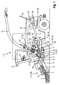
- Fig. 1 shows an executed as a forage harvester 2 agricultural machine 1, which receives in its front area as a pick-up 4 running attachment 3.
- a pick-up for example, a maize header can be used.
- the pick-up 4 is designed such that it receives a crop strand 5 between a hold-down device 6 and a pick-up drum 7 and supplies in the rear region of the pick-up 4 a cross auger 8.
- the cross auger 8 passes the crop 5 almost centrally of the pick-up 4 downstream Einzugorganen 9.
- the retraction members 9 are formed by paired feed rollers 10 and this downstream pre-compression rollers 11. After the crop strand 5 has passed the intake elements 9, it is transferred to a chopper drum 12 in the rear region thereof.
- the chopper drum 12 receives at its periphery a plurality of chopping blades 13, which the Erntegutstrang 5 crushed in cooperation with a counter-blade 14. Due to the kinetic energy of the rotating chopper drum 12, the crop strand 5 emerges at high speed from the chopper drum 12 in the rear region thereof and is transferred to cracker rollers 15 arranged in pairs.
- the cracker rollers 15 form a so-called post-shredding device 16, which can optionally be used. After the crop strand 5 has passed the post-shredding device 16, it passes into the effective range of a post-accelerator 17.
- the post-accelerator 17 imposes additional kinetic energy on the crop strand 5 in a manner known per se, by means of which the crop strand 5 is directed via a discharge chute pointing essentially in the vertical direction 18 and a subordinate pivoting and rotating ejection elbow 19 is conveyed out of the forage harvester 2.
- the attachment 3, the intake organs 9, the chopper drum 12, the optional post-shredding device 16, and the post-accelerator 17 form the working members 20 of the agricultural machine 1 according to the invention.
- the forage harvester 2 is associated with at least one drive motor 25, the output side pulley 26 is wrapped by a drive belt 27.
- the main drive belt 28 extends between the output side pulley 26 of the drive motor 25 and one of the drive shaft 29 of the chopper drum 12 associated pulley 30.
- the so-called Switzerland 31 directly between the chopper drum 12th and the pulley 26 of the drive motor 25 extends and is free of further energieabietyden elements, the other in the following to be described in more detail 32 and clamping devices 33 are arranged in the so-called Leertrum 34.
- the chopper drum 12 is supplied with drive power pulley 30 in the vertical direction deeper than the drive motor 25 associated pulley 26.
- the input and output unit 24 of the control unit 23 is designed, for example, as a keyboard and a display unit.
- Fig. 2 is a schematic view of a drive system shown in plan view.
- a pulley 36 is disposed on the Nachbeschreiberwelle 35, which is at least partially wrapped by the main drive belt 28.
- the post-accelerator shaft 35 is assigned to one end a gear stage 37, by means of which the optional post-shredding device 16 can be driven.
- the gear stage 37 by means of which the optional post-shredding device 16 can be driven.
- the main drive belt 28 is assigned a further pulley 38.
- This pulley 38 is penetrated by an output shaft 39 which is coupled at one end to the drive shaft 40 of a hydraulic pump 41 designed as an axial piston pump.
- the hydraulic pump 41 is assigned a pipeline system 42 as part of a hydraulic system.
- the pipeline system 42 opens at the other end into a hydraulic motor 43, whose output shaft 44 is coupled to the input shaft 45 of a gear unit 46.
- a control valve assembly 47 is integrated into the pipeline system 42, which controls a pressure oil flow exchange between the hydraulic pump 41 and the hydraulic motor 43 in such a way that the control valve assembly 47 can interrupt the hydraulic oil flow between the hydraulic pump 41 and hydraulic motor 43, so that the intake organs 9 abruptly Come to a standstill.
- this function is required in connection with so-called foreign body detectors, since in a conventional manner on the detection of foreign bodies, the intake organs 9 are stopped, so that the detected foreign body does not enter the other working organs of the forage harvester 2. It is within the scope of the invention that the control of the pressure oil flows in a conventional manner can be carried out automatically or by an operator of the forage harvester 2 targeted.
- the gear unit 46 forms the drive unit 48 for driving the retraction members 9, wherein in a conventional manner the retraction members 9 a so-called transfer gear 49 is assigned and between the transfer gear 49 and the gear unit 46 at least one propeller shaft 50 interposed to transmit the drive energy is.
- the drive unit 48 forming the gear unit 46 is at least partially disposed in a region which is bounded in the vertical direction by the Glastrum 31 and the backbone 34 of the main drive belt 28 and also in the rear region of in FIG. 1 shown front axle 22 is located.
- the drive unit 48 of the intake organs 9 is assigned a consisting of the hydraulic pump 41 and the hydraulic motor 43 hydraulic unit 51, the speed of the intake organs 9 can be adjusted continuously.
- the hydraulic unit 51 and the gear unit 46 form the hydromechanical gear unit 52.
- the pulley 38 at the same time forms an output 32 according to the invention which cooperates with the main drive belt 28.
- FIG. 3 shows a partial sectional view of the axial piston pump designed as a hydraulic pump 41 with a valve assembly disposed thereon 67 and in a schematic representation of components of the control valve assembly 47.
- the illustration in Fig. 3 shows only a portion of a surrounding the hydraulic pump 41 housing 66 to which the arranged in a valve assembly housing 83 valve assembly 67 is connectable.
- the delivery volume and the conveying direction of the hydraulic pump 41 can be varied by changing its pivot angle, which is achieved in axial piston pumps by a change in position of their sliding disk.
- To the valve assembly 67 line of the piping system 42 can be connected to supply the hydraulic pump 41 with hydraulic oil.
- the housing 66 has an inlet 68 and a drain 69, to each of which an inlet valve 70 and an outlet valve 71 is assigned.
- the valve assembly 67 on the side of the drain 69 comprises a restriction device 72, which has a bolt 73 and a cylindrical piston 74 adjoining it.
- the bolt 73 is guided in a bolt guide 82, which is part of the limiting device 72, in the axial direction.
- An annular chamber 81 is formed between the pin guide 82 and the valve assembly housing 83 accommodating the inlet valve 70, the outlet valve 71 and the mechanical limiting device 72, among other things.
- the control valve arrangement 47 in each case comprises a first control valve 47a integrated into the pipeline system 42 and a second control valve 47b, which are each connected by hydraulic lines 84 to a tank 75.
- the intake valves 70 and the exhaust valve 71 are based on the piston longitudinal slide type.
- the respective pistons 70a, 71a of the intake valve 70 and the exhaust valve 71 are subjected to a constant hydraulic pressure in the regular operation of the intake elements 9.
- the sealing elements 70b, 71b are also pressurized, but since their surface area is smaller than that of the pistons 70a, 71a, the inlet valve 70 and the outlet valve 71 are closed.
- the pressurization of the pistons 70a, 71a to keep the intake valve 70 and the exhaust valve 71 closed, or the interruption of the pressurization to open the intake valve 70 and the exhaust valve 71, is controlled by the second control valve 47b.
- the inlet 76 is further preceded by an orifice 80, which reduces the pressure of the hydraulic oil on the piston 70 a of the inlet valve 70 side facing away.
- the piston 74 of the restriction device 72 is pressurized by means of the first control valve 47a.
- the piston surface formed by the bolt 73 and the annular guide 82 the bolt guide 82 is acted upon by a pump side pending pressure, whereby the limiting device 72 is held in an equilibrium position, the zero position of the sliding disk of the hydraulic pump 41 corresponds, that is, that no hydraulic oil is conveyed.
- This position of the bolt 73 which is adjusted by the balance of the pressure forces, is determined and adjusted by a calibration process, which is carried out with the respective hydraulic pump 41.
- the first control valve 47a also has the task of being able to retract the pin 73 of the limiting device 72, in order to achieve a corresponding direction of flow reversal of the hydraulic pump 41 with a necessary reversing of the intake organs 9.
- the first control valve 47a is switched by the control unit 23 such that the surface of the piston 74 of the restriction device 72 is pressurized.
- the force applied by the pivoting cradle counterforce from the control pressure of the reversing causes in the case of reversing that the pivot angle of the sliding disk can assume a position in which the conveying direction of the hydraulic pump 41 reverses.
- the control of the second control valve 47b remains unchanged in this situation or the second control valve 47b, if a quick stop was performed before the reversing controlled by the control unit 23 again in order to achieve this operating situation.
- FIG. 3 shows a situation of the drive system in which the retraction members 9 are operated regularly, wherein the bolt 73 of the restriction device 72 protrudes into the housing 66 of the hydraulic pump 41 to serve as a zero stop in a foreign body detection can.
- the first control valve 47a and the second control valve 47b are controlled by the control unit 23 such that the hydraulic pump 41 is in its normal operating mode for driving the intake organs 9.
- the first control valve 47a is actuated in this operating situation in order to pressurize the piston 74 with a pressurized hydraulic oil, which transfers the Bolts 73 of the limiting device 72 in its position and which corresponds to the zero position of the sliding disk 41 of the hydraulic pump.
- the inlet valve 70 and the outlet valve 71 are pressurized on the piston side, around the inlet valve 70 and the outlet valve 71 in their line sections 78, 79, the inlet 68 and outlet 69 with one on the valve assembly 67 provided inlet 76 and outlet 77 connect to keep occlusive position.
- the hydraulic oil necessary for this purpose can be provided, for example, by a constant pressure system provided on the forage harvester 2. Hydraulic oil, whose pressure is lower than the pressure on the piston side of the inlet valve 70, is also supplied through the inlet 76 on the side facing the sealing element 70b, so that the inlet valve 70 remains closed. In a corresponding manner, the outlet valve 71 is subjected to a pressure on the piston side in order to keep it in the closed position as well.
- the change in the pivot angle of the hydraulic pump 41 is limited by the projecting into the housing 66 bolt 73 in such a way that the delivery volume of the hydraulic pump 41 reaches a value of zero abruptly.
- the hydraulic oil flowing into the housing 66 through the inlet 68 causes the sliding disk of the hydraulic pump 41 to be kept in its zero position in this position, in which it is pressed against the bolt 73 on the outlet side.
- the retraction members 9 are driven reversibly in general to be able to excrete recorded foreign matter.
- the second control valve 47b is controlled by the control unit 23 in such a way that the inlet valve 70 and the outlet valve 71 are closed again, which by the pressurization of the Piston 70a, 71a is achieved.
- the first control valve 47a is actuated by the control unit 23 in order to retract the pin 73 of the limiting device 72, so that the pivoting angle of the hydraulic pump 41 can assume a value less than 0 °, which leads to a reversing of the intake elements 9.
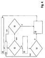
- Fig. 4 1 illustrates the method for operating the working machine 1 designed as a forage harvester 2 with reference to a flow chart.
- the first control valve 47a is actuated by the control unit 23 to transfer the limiting device 72 to its limiting position, that is, in which the limiting device 72 acts as a mechanical zero stop of the hydraulic pump 41.
- step 91 the monitoring or detection of the presence of an operating state by the control unit 23, which is representative of the penetration of a foreign body in the retraction member 9 of the work machine 2 or triggering a reversing process of the retraction member 9.
- step 92 a query is made as to whether there is an operating state which represents the penetration of a foreign body into the intake element 9. If an intrusion of a foreign body into the intake element has been detected, the second control valve 47b is actuated by the control unit 23 in step 93. The drive causes the inlet valve 70 and the outlet valve 71 to be opened. This triggers, as already stated above, the rapid stop of the hydraulic pump 41 and thus of the intake organ 9 from. In order to eliminate debris present in the intake element 9, the intake element 9 is generally reversibly driven, which is triggered manually or automatically, is detected in step 94.
- the first control valve 47a is activated in step 95 in such a way that the limiting device 72 is brought into a reversing position, that is, the function of the limiting element 72 is deactivated, such as is carried out above, so that the hydraulic pump has a negative delivery volume, which leads to a slow reversal of the intake organ 9.
- step 96 If no foreign body was detected in step 92, it is checked in step 96 whether a reversing process was triggered, which represents a common measure in the case of a crop accumulation in the intake element 9 of the forage harvester 2. If there is a signal representing the triggering of a reversing process of the retraction element 9, then the first control valve 47a is activated in such a way that the limiting device 72 is transferred into its reversing position.
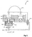
- FIG. 5 is a partial sectional view of an axial piston pump designed as a hydraulic pump 100 shown with a control valve associated therewith and a limiting device according to a second embodiment.
- the hydraulic pump 100 is arranged in a housing 101, which is shown only partially in the sectional view. Inside the housing 101 is a pivoting cradle 102, the deflection causes a change in the pivot angle of the hydraulic pump 100.
- the pivoting angle of the pivoting cradle 102 is adjustable by a solenoid valve 103.
- a limiting device 104 is arranged, which is controllable by a control valve 105.
- the limiting device 104 comprises a bolt 108 which is arranged in a housing 109 which can be flange-mounted to the housing 101.
- the bolt 108 is slidably mounted relative to the housing 109 and passes through an opening in the housing 101 of the hydraulic pump 100 in its interior.
- a bottom member 110 is arranged, which has a larger base than the bolt 108.
- the bolt 108 is connected by a screw connection to the bottom element 110.
- a pressure source 106 acts on the solenoid valve 103 or the control valve 105 with a hydraulic pressure. Furthermore, a tank 107 is provided, with which the hydraulic pump 100 is connected by lines Fig. 5 shows an operating situation of the hydraulic pump 100, in which the hydraulic pump 100 promotes no hydraulic oil due to a quick stop.
- the solenoid valve 103 is de-energized, so that the pivoting cradle 102 strives for a negative pivot angle.
- the movement of the pivoting cradle 102 is by a in the housing 101 of the Limited hydraulic pump 100 projecting piston 108, which is part of the limiting device 104.
- the control valve 105 is controlled in this operating situation such that the bolt 108 is acted upon on its side facing away from the housing 101 with a hydraulic pressure which is provided by the pressure source 106. In this way, the bolt 108 is transferred to a position corresponding to the zero stop of the hydraulic pump 100.
- Fig. 6 shows a partial sectional view of a designed as an axial piston hydraulic pump 100 with a control valve associated therewith 105 and a limiting device 104 according to the second embodiment in a second operating situation.
- the illustrated operating situation shows the hydraulic pump 100 during reversing.
- the solenoid valve 103 is also de-energized, as is the case with the rapid stop.
- the pivoting cradle 102 strives for a negative pivoting angle due to its weight distribution.
- the control valve 105 is controlled such that the hydraulic oil in the housing 109, with which the bolt 108 is acted upon, can flow into the tank 107.
- the pin 108 Due to the weight of the pivoting cradle 102 and the lack of back pressure, the pin 108 is pushed out of the interior of the housing 101. Due to the omission of the mechanical stop inside the housing 101 of the hydraulic pump 100, the pivoting cradle assumes a negative pivoting angle.
Landscapes
- Engineering & Computer Science (AREA)
- Mechanical Engineering (AREA)
- General Engineering & Computer Science (AREA)
- Life Sciences & Earth Sciences (AREA)
- Environmental Sciences (AREA)
- Chemical & Material Sciences (AREA)
- Analytical Chemistry (AREA)
- Physics & Mathematics (AREA)
- Fluid Mechanics (AREA)
- Fluid-Pressure Circuits (AREA)
Description
- Die vorliegende Erfindung betrifft ein Antriebssystem für hydraulisch angetriebene Arbeitsorgane einer Arbeitsmaschine gemäß dem Oberbegriff des Anspruches 1 sowie ein Verfahren zum Betreiben eines Antriebssystems für hydraulisch angetriebene Arbeitsorgane einer Arbeitsmaschine gemäß dem Oberbegriff des Anspruches 11.
- Aus der
EP 2 312 928 A1 ist ein Antriebssystem für einen Einzugförderer einer Erntemaschine bekannt, das eine verstellbare Hydropumpe umfasst, deren Flussrate und Flussrichtung durch einen doppeltwirkenden Hydraulikzylinder verstellbar ist. Der Hydraulikzylinder wird hierzu durch ein elektromagnetisches Ventil über eine Steuereinheit angesteuert. Im Fall der Detektion eines Fremdkörpers in dem Einzugförderer wird das elektromagnetische Ventil durch die Steuereinheit temporär derart angesteuert, dass eine Umkehrung der Förderrichtung einsetzt, so dass sich die Hydropumpe nicht mehr nennenswert in der Förderrichtung drehen sollte. Ein wesentlicher Nachteil besteht darin, dass das Fördervolumen nicht auf null beschränkbar ist, was Toleranzen im Antriebssystem geschuldet ist. Ein Nachteil, der aus der Ansteuerung des Magnetventiles resultiert, besteht darin, dass die Dynamik, mit der das Magnetventil im Fall einer Fremdkörperdetektion den Schnellstopp auslöst, zu gering ist, um den hohen Anforderungen an die Betriebssicherheit im Fall eines Schnellstopps zu genügen. Um eine schnellstmögliche Richtungsumkehr der Förderrichtung zu erzielen, wird das Magnetventil stromlos geschaltet, damit sich das Magnetfeld schnell abbauen kann. Im Anschluss daran wird das Magnetventil wieder bestromt, wodurch die Nullstellung der Hydropumpe angesteuert wird. - Aufgabe der vorliegenden Erfindung ist es, ein Antriebssystem der eingangs genannten Art derart weiterzuentwickeln, dass im Fall eines Schnellstopps eines Arbeitsorganes der Arbeitsmaschine die Axialkolbenpumpe ihre Nullstellung schnell und präzise einnimmt. Weiterhin liegt der Erfindung die Aufgabe zu Grunde, ein Verfahren zum Betreiben einer Arbeitsmaschine bereitzustellen, die das schnelle und genaue Erreichen der Nullstellung der Axialkolbenpumpe ermöglicht.
- Diese Aufgabe wird vorrichtungsseitig durch die kennzeichnenden Merkmale des Anspruches 1 und verfahrensseitig durch die kennzeichnenden Merkmale des Anspruches 11 gelöst.
- Gemäß dem Vorrichtungsanspruch 1 wird vorgeschlagen, dass das Antriebssystem eine von der Steuereinheit ansteuerbare Steuerventilanordnung aufweist, durch welche eine Begrenzungsvorrichtung, die ein kolbenförmiges Element aufweist, welches zumindest einseitig hydraulisch druckbeaufschlagbar ist, ansteuerbar ist, durch die der Schwenkwinkel der Axialkolbenpumpe mechanisch auf null Grad (0°) festlegbar ist. Eine schnelle Veränderung des Schwenkwinkels bewirkt eine Umkehr der Förderrichtung, wenn der Schwenkwinkel durch null ins Negative geht. Deshalb wird eine Veränderung des Schwenkwinkels ins Negative durch die Begrenzungsvorrichtung abrupt gestoppt und in dieser Anschlagsposition gehalten. Dadurch ist gewährleistet, dass die Axialkolbenpumpe im Fall eines Schnellstopps eines Arbeitsorganes keine Förderleistung aufweist. Hierbei fungiert die Begrenzungsvorrichtung als einfachwirkender Zylinder. Auf der einen Seite ist das kolbenförmige Element mit einem Hydraulikdruck beaufschlagbar, während auf der anderen Seite die Gewichtskraft der Schwenkwiege der Axialkolbenpumpe wirkt. Somit kann ohne ein zusätzliches Rückstellmittel gearbeitet werden, um unterschiedliche Positionen einnehmen zu können, die für einen Schnellstopp sowie das Reversieren notwendig sind.
- Vorteilhafterweise kann die Steuerventilanordnung eine Ventilbaugruppe sowie ein erstes und ein zweites Steuerventil umfassen. Durch den Einsatz mehrerer Steuerventile kann neben dem Schnellstopp auch ein Reversieren des Hydromotors realisiert werden. Dabei kann das Reversieren unabhängig von einem Schnellstopp durchgeführt werden.
- Weiterhin kann die Ventilbaugruppe ein Ventilbaugruppengehäuse umfassen, in welchem ein Einlassventil und ein Auslassventil sowie die Begrenzungsvorrichtung angeordnet sind.
- In vorteilhafter Weiterbildung kann die Begrenzungsvorrichtung derart verstellbar sein, dass die Förderrichtung der Axialkolbenpumpe umkehrbar ist. Hierdurch kann das Antriebssystem auch reversierend betrieben werden.
- Insbesondere kann die Begrenzungsvorrichtung durch das erste Steuerventil ansteuerbar sein. Hierdurch kann die Begrenzungsvorrichtung individuell angesteuert werden, was für das Durchführen eines Schnellstopps sowie das Reversieren des Hydromotors vorteilhaft ist. Des Weiteren ermöglicht die Ansteuerung durch das erste Steuerventil eine einfache Einstellung der Begrenzungsvorrichtung, um diese an die tatsächliche Nullstellung des Schwenkwinkels anpassen zu können.
- Des Weiteren kann das zweite Steuerventil das Einlassventil und das Auslassventil, welche den Zufluss sowie den Abfluss von Hydrauliköl zu beziehungsweise von der Axialkolbenpumpe steuern, ansteuern. Das Einlassventil als auch das Auslassventil können als Schieberventile ausgeführt sein.
- Vorteilhafterweise kann die Steuereinheit zur Detektion eines Betriebszustandes der Arbeitsmaschine eingerichtet sein, der für das Eindringen eines Fremdkörpers in ein Arbeitsorgan der Arbeitsmaschine oder ein Auslösen eines Reversiervorganges eines Arbeitsorganes repräsentativ ist. Auf diese Weise kann sichergestellt werden, dass die Ansteuerung des ersten Steuerventiles beziehungsweise des zweiten Steuerventiles durch die Steuereinheit entsprechend des sich einstellenden Betriebszustandes aufeinander abgestimmt erfolgt.
- Des Weiteren betrifft die Erfindung ein Verfahren zum Betreiben eines Antriebssystems für hydraulisch angetriebene Arbeitsorgane einer Arbeitsmaschine, mit einer Axialkolbenpumpe, deren Fördervolumen und Förderrichtung durch Veränderung ihres Schwenkwinkels variiert wird, einen mit der Axialkolbenpumpe leitungsverbundenden Hydromotor, der mit den Arbeitsorganen in Antriebsverbindung steht, sowie eine Steuereinheit, die derart betreibbar ist, dass das Fördervolumen der Axialkolbenpumpe auf null gestellt wird.
- Gemäß dem Verfahrensanspruch 11 wird vorgeschlagen, dass das Vorliegen eines Betriebszustandes detektiert wird, der für das Eindringen eines Fremdkörpers in ein Arbeitsorgan der Arbeitsmaschine oder ein Auslösen eines Reversiervorganges eines Arbeitsorganes repräsentativ ist, und dass in Abhängigkeit von dem detektierten Betriebszustand durch die Steuereinheit eine Aktorik zur Ansteuerung einer Begrenzungsvorrichtung, die ein kolbenförmiges Element aufweist, welches zumindest einseitig hydraulisch druckbeaufschlagbar ist, angesteuert wird, mittels der der Schwenkwinkel der Axialkolbenpumpe mechanisch dem Betriebszustand entsprechend festgelegt wird. Auf diese Weise lassen sich Betriebszustände abbilden, die dem Schnellstopp oder dem Reversieren des Arbeitsaggregates entsprechen.
- Vorteilhafterweise kann von der Steuereinheit ein erstes Steuerventil der Steuerventilanordnung derart angesteuert werden, dass die Begrenzungsvorrichtung in eine Stellung überführt wird, in welcher der Schwenkwinkel der Axialkolbenpumpe durch die Begrenzungsvorrichtung auf null festgelegt wird.
- Dabei kann bei Detektion des Auslösens eines Reversiervorganges das erste Steuerventil der Steuerventilanordnung derart angesteuert werden, dass die Begrenzungsvorrichtung in eine Stellung überführt wird, in der die Axialkolbenpumpe reversierend betreibbar ist.
- Im einfachsten Fall ist ein Steuerventil vorgesehen, welches die Begrenzungsvorrichtung ansteuert. Hierbei wird das kolbenförmige Element mit einem Hydraulikdruck beaufschlagt, so dass das kolbenförmige Element soweit in das Innere des Gehäuses der Axialkolbenpumpe ragt, wie es der Nullstellung des Schwenkwinkels entspricht. Vorzugsweise wird die Bewegung des kolbenförmigen Elementes durch einen Anschlag am oder im Gehäuse begrenzt. Für das Reversieren wird das Steuerventil derart angesteuert, dass das kolbenförmige Element nicht mit Hydraulikdruck beaufschlagt wird. Gewichtskraftbedingt wird das kolbenförmige Element in eine Stellung überführt, in welcher es nicht in das Innere der Axialkolbenpumpe hineinragt. Durch den Fortfall der mechanischen Begrenzung der Nullstellung des Schwenkwinkels kann dieser einen negativen Wert annehmen, der dem reversierenden Betrieb der Axialkolbenpumpe entspricht.
- Insbesondere kann bei Detektion eines Fremdkörpers in einem Arbeitsorgan von der Steuereinheit ein zweites Steuerventil derart angesteuert werden, dass die Axialkolbenpumpe eine Förderrichtungsumkehr erfährt.
- Die vorliegende Erfindung wird nachstehend anhand eines in den Zeichnungen dargestellten Ausführungsbeispieles näher erläutert.
- Es zeigen:
- Fig. 1
- eine schematische Seitenansicht eines Feldhäcksler;
- Fig. 2
- eine Detaildraufsicht auf ein Antriebssystems des Feldhäckslers;
- Fig. 3
- eine Teilschnittansicht einer Axialkolbenpumpe mit einer daran angeordneten Ventilbaugruppe;
- Fig. 4
- ein Flussdiagramm;
- Fig. 5
- eine Teilschnittansicht einer Axialkolbenpumpe mit einer daran angeordneten Ventilbaugruppe gemäß einer zweiten Ausführungsform in einer ersten Betriebssituation;
- Fig. 6
- eine Teilschnittansicht einer Axialkolbenpumpe mit einer daran angeordneten Ventilbaugruppe gemäß einer zweiten Ausführungsform in einer zweiten Betriebssituation.
-
Fig. 1 zeigt eine als Feldhäcksler 2 ausgeführte landwirtschaftliche Arbeitsmaschine 1, die in ihrem frontseitigen Bereich ein als Pick-up 4 ausgeführtes Vorsatzgerät 3 aufnimmt. Anstelle einer Pick-up kann beispielsweise auch ein Maisgebiss zum Einsatz kommen. Die Pick-up 4 ist so gestaltet, dass sie einen Erntegutstrang 5 zwischen einer Niederhaltereinrichtung 6 und einer Aufsammeltrommel 7 aufnimmt und im rückwärtigen Bereich der Pick-up 4 einer Querförderschnecke 8 zuführt. Die Querförderschnecke 8 übergibt das Erntegut 5 nahezu mittig der Pick-up 4 nachgeordneten Einzugorganen 9. Im dargestellten Ausführungsbeispiel werden die Einzugorgane 9 von paarweise angeordneten Einzugswalzen 10 und diesen nachgeordneten Vorpresswalzen 11 gebildet. Nachdem der Erntegutstrang 5 die Einzugorgane 9 passiert hat, wird er in deren rückwärtigen Bereich an eine Häckseltrommel 12 übergeben. Die Häckseltrommel 12 nimmt an ihrem Umfang eine Vielzahl von Häckselmessern 13 auf, die den Erntegutstrang 5 im Zusammenwirken mit einer Gegenschneide 14 zerkleinert. Durch die kinetische Energie der umlaufenden Häckseltrommel 12 tritt der Erntegutstrang 5 im rückwärtigen Bereich der Häckseltrommel 12 mit hoher Geschwindigkeit aus dieser aus und wird an paarweise angeordnete Crackerwalzen 15 übergeben. Die Crackerwalzen 15 bilden dabei eine sogenannte Nachzerkleinerungseinrichtung 16, die optional zum Einsatz kommen kann. Nachdem der Erntegutstrang 5 die Nachzerkleinerungseinrichtung 16 passiert hat, gelangt er in den Wirkbereich eines Nachbeschleunigers 17. Der Nachbeschleuniger 17 prägt dem Erntegutstrang 5 in an sich bekannter Weise zusätzliche kinetische Energie auf, mittels derer der Erntegutstrang 5 über einen im Wesentlichen in vertikaler Richtung weisenden Auswurfschacht 18 und einen diesem nachgeordneten schwenk- und drehbeweglichen Auswurfkrümmer 19 aus dem Feldhäcksler 2 herausgefördert wird. Im dargestellten Ausführungsbeispiel bilden das Vorsatzgerät 3, die Einzugorgane 9, die Häckseltrommel 12, die optionale Nachzerkleinerungseinrichtung 16, sowie der Nachbeschleuniger 17 die erfindungsgemäßen Arbeitsorgane 20 der landwirtschaftlichen Arbeitsmaschine 1. - Weiter ist dem Feldhäcksler 2 zumindest ein Antriebsmotor 25 zugeordnet, dessen abtriebsseitige Riemenscheibe 26 von einem Antriebsriemen 27 umschlungen wird. Der Antriebsriemen 27 bildet in erfindungsgemäßer Weise einen Hauptantriebsriemen 28. Im dargestellten Ausführungsbeispiel erstreckt sich der Hauptantriebsriemen 28 zwischen der abtriebsseitigen Riemenscheibe 26 des Antriebsmotors 25 und einer der Antriebswelle 29 der Häckseltrommel 12 zugeordneten Riemenscheibe 30. Während sich das sogenannte Zugtrum 31 unmittelbar zwischen der Häckseltrommel 12 und der Riemenscheibe 26 des Antriebsmotors 25 erstreckt und frei von weiteren energieabgreifenden Elementen ist, sind die weiteren im folgenden noch näher zu beschreibenden Abtriebe 32 und Spanneinrichtungen 33 in dem sogenannten Leertrum 34 angeordnet. Im dargestellten Ausführungsbeispiel liegt die, die Häckseltrommel 12 mit Antriebsenergie versorgende Riemenscheibe 30 in vertikaler Richtung tiefer als die dem Antriebsmotor 25 zugeordnete Riemenscheibe 26. In der Kabine 21 des Feldhäckslers 2 befindet sich eine Ein- und Ausgabeeinheit 24 einer Steuereinheit 23, die unter anderem der Steuerung der Einzugorgane 9 dient. Die Ein- und Ausgabeeinheit 24 der Steuereinheit 23 ist beispielsweise als eine Tastatur und eine Bildschirmeinheit ausgeführt.
- In
Fig. 2 ist eine schematische Ansicht eines Antriebssystems in Draufsicht dargestellt. In einer vertikal höchsten Position ist auf der Nachbeschleunigerwelle 35 eine Riemenscheibe 36 angeordnet, die zumindest teilweise von dem Hauptantriebsriemen 28 umschlungen wird. In an sich bekannter Weise ist der Nachbeschleunigerwelle 35 einem Ende eine Getriebestufe 37 zugeordnet, mittels derer die optionale Nachzerkleinerungseinrichtung 16 antreibbar ist. Auf diese Weise ist mittels der Riemenscheibe 36 zugleich der Nachbeschleuniger 17 und die Nachzerkleinerungseinrichtung 16 antreibbar, sodass diese Riemenscheibe 36 einen der dem Hautantriebsriemen zugeordneten Abtriebe 32 bildet. In vertikaler Richtung zwischen der Position, der dem Antriebsmotor 25 zugeordneten Riemenscheibe 26 und der Nachbeschleunigerwelle 35 zugeordneten Riemenscheibe 30 und in Längsrichtung des Feldhäcksler 2 etwa mittig zwischen beiden ist dem Hauptantriebsriemen 28 eine weitere Riemenscheibe 38 zugeordnet. Diese Riemenscheibe 38 wird von einer Abtriebswelle 39 durchsetzt, die mit einem Ende mit der Antriebswelle 40 einer als Axialkolbenpumpe ausgeführten Hydropumpe 41 gekoppelt ist. Abtriebsseitig ist der Hydropumpe 41 ein Rohrleitungssystem 42 zugeordnet als Teil eines Hydrauliksystems. Das Rohrleitungssystem 42 mündet mit dem anderen Ende in einen Hydromotor 43, dessen Abtriebswelle 44 mit der Eingangswelle 45 einer Getriebeeinheit 46 gekoppelt ist. Zugleich ist in das Rohrleitungssystem 42 eine Steuerventilanordnung 47 integriert, die einen Druckölstromaustausch zwischen der Hydropumpe 41 und dem Hydromotor 43 steuert und zwar in der Weise, dass die Steuerventilanordnung 47 den Hydraulikölstrom zwischen Hydropumpe 41 und Hydromotor 43 unterbrechen kann, sodass die Einzugorgane 9 schlagartig zum Stillstand kommen. In an sich bekannter Weise wird diese Funktion im Zusammenhang mit sogenannten Fremdkörperdetektoren benötigt, da in an sich bekannter Weise auf deren Detektion von Fremdkörpern die Einzugorgane 9 gestoppt werden, damit die detektierten Fremdkörper nicht in die weiteren Arbeitsorgane des Feldhäckslers 2 gelangen. Es liegt im Rahmen der Erfindung, dass die Steuerung der Druckölströme in an sich bekannter Weise selbsttätig oder durch eine Bedienperson des Feldhäckslers 2 gezielt vorgenommen werden kann. - Die Getriebeeinheit 46 bildet die Antriebseinheit 48 zum Antrieb der Einzugorgane 9, wobei in an sich bekannter Weise den Einzugsorganen 9 ein sogenanntes Verteilgetriebe 49 zugeordnet ist und zwischen dem Verteilgetriebe 49 und der Getriebeeinheit 46 zumindest eine Gelenkwelle 50 zur Übertragung der Antriebsenergie zwischengeschaltet ist. Die die Antriebseinheit 48 bildende Getriebeeinheit 46 ist zumindest teilweise in einem Bereich angeordnet, der in vertikaler Richtung durch das Zugtrum 31 und das Leertrum 34 des Hauptantriebsriemens 28 begrenzt wird und zudem im rückwärtigen Bereich der in
Figur 1 dargestellten Vorderachse 22 liegt. Indem der Antriebseinheit 48 der Einzugorgane 9 eine aus der Hydropumpe 41 und dem Hydromotor 43 bestehende hydraulische Einheit 51 zugeordnet ist, kann die Drehzahl der Einzugorgane 9 stufenlos eingestellt werden. Die hydraulische Einheit 51 und die Getriebeeinheit 46 bilden die hydromechanische Getriebeeinheit 52. Gemäß den vorherigen Ausführungen bildet die Riemenscheibe 38 zugleich einem mit dem Hauptantriebsriemen 28 zusammenwirkenden erfindungsgemäßen Abtrieb 32. - Die Darstellung in
Fig. 3 zeigt eine Teilschnittansicht der als Axialkolbenpumpe ausgeführten Hydropumpe 41 mit einer daran angeordneter Ventilbaugruppe 67 sowie in schematischer Darstellung Komponenten der Steuerventilanordnung 47. Die Darstellung inFig. 3 zeigt lediglich einen Teil eines die Hydropumpe 41 umgebenden Gehäuses 66, an dem die in einem Ventilbaugruppengehäuse 83 angeordnete Ventilbaugruppe 67 anschließbar ist. Das Fördervolumen und die Förderrichtung der Hydropumpe 41 ist durch Veränderung ihres Schwenkwinkels variierbar, was bei Axialkolbenpumpen durch eine Lageänderung ihrer Gleitscheibe erreicht wird. An die Ventilbaugruppe 67 sind Leitung des Rohrleitungssystems 42 anschließbar, um die Hydropumpe 41 mit Hydrauliköl zu versorgen. Das Gehäuse 66 weist einen Zulauf 68 und einen Ablauf 69 auf, denen jeweils ein Einlassventil 70 beziehungsweise ein Auslassventil 71 zugeordnet ist. Des Weiteren umfasst die Ventilbaugruppe 67 auf der Seite des Ablaufs 69 eine Begrenzungsvorrichtung 72, die einen Bolzen 73 und einen sich daran anschließenden zylindrischen Kolben 74 aufweist. Der Bolzen 73 ist in einer Bolzenführung 82, welche Teil der Begrenzungsvorrichtung 72 ist, in axialer Richtung geführt. Zwischen der Bolzenführung 82 und dem unter anderem das Einlassventil 70, das Auslassventil 71 sowie die mechanische Begrenzungsvorrichtung 72 aufnehmenden Ventilbaugruppengehäuse 83 bildet sich eine Ringkammer 81 aus. Weiterhin umfasst die Steuerventilanordnung 47 jeweils ein in das Rohrleitungssystem 42 integriertes erstes Steuerventil 47a und ein zweites Steuerventil 47b, die jeweils durch Hydraulikleitungen 84 mit einem Tank 75 verbunden sind. - Gemäß der Darstellung in
Fig. 3 basieren das Einlassventile 70 und das Auslassventil 71 auf der Kolbenlängsschieberbauart. Die jeweiligen Kolben 70a, 71 a des Einlassventiles 70 und des Auslassventiles 71 sind im regulären Betrieb der Einzugorgane 9 mit einem konstanten Hydraulikdruck beaufschlagt. Auf der den Kolben 70a, 71 a abgewandten Seite des jeweiligen Einlassventiles 70 beziehungsweise Auslassventiles 71 befindet sich jeweils ein Dichtelement 70b, 71 b, welches Leitungsabschnitte 78, 79, die den Zulauf 68 beziehungsweise Ablauf 69 mit einem an der Ventilbaugruppe 67 vorgesehenen Einlass 76 beziehungsweise Auslass 77 verbinden, verschließen beziehungsweise freigeben kann. Die Dichtelemente 70b, 71 b sind ebenfalls mit einem Druck beaufschlagt, da jedoch deren Oberfläche kleiner ist, als die der Kolben 70a, 71a, sind das Einlassventil 70 und das Auslassventil 71 geschlossen. Die Druckbeaufschlagung der Kolben 70a, 71 a, um das Einlassventil 70 und das Auslassventil 71 geschlossen zu halten, beziehungsweise die Unterbrechung der Druckbeaufschlagung, um das Einlassventil 70 und das Auslassventil 71 zu öffnen, wird durch das zweite Steuerventil 47b gesteuert. - Dem Einlass 76 vorgeschaltet ist weiterhin eine Drosselblende 80, die den Druck des Hydrauliköls auf der dem Kolben 70a des Einlassventils 70 abgewandten Seite reduziert.
- Auf der Seite des Auslasses 77 wird der Kolben 74 der Begrenzungsvorrichtung 72 mittels des ersten Steuerventils 47a mit einem Druck beaufschlagt. Auf der dem Gehäuse 66 der Hydropumpe 41 zugewandten Seite werden die von dem Bolzen 73 gebildete Kolbenfläche sowie durch die Ringkammer 82 die Bolzenführung 82 mit einem pumpenseitig anstehenden Druck beaufschlagt, wodurch die Begrenzungsvorrichtung 72 in einer Gleichgewichtsstellung gehalten wird, die der Nulllage der Gleitscheibe der Hydropumpe 41 entspricht, das heißt, dass kein Hydrauliköl gefördert wird. Diese Position des Bolzens 73, die sich durch das Gleichgewicht der Druckkräfte einstellt, wird durch einen Kalibriervorgang ermittelt und eingestellt, der mit der jeweiligen Hydropumpe 41 durchzuführen ist.
- Weiterhin kommt dem ersten Steuerventil 47a neben der Funktion des Einstellbarkeit der Begrenzungsvorrichtung 72 zur Einstellung der Nulllage der Hydropumpe 41 auch die Aufgabe zu, den Bolzen 73 der Begrenzungsvorrichtung 72 einziehen zu können, um bei einem notwendigen Reversieren der Einzugorgane 9 eine entsprechende Förderrichtungsumkehr der Hydropumpe 41 erreichen. Hierzu wird das erste Steuerventil 47a von der Steuereinheit 23 derart geschaltet, dass die Fläche des Kolbens 74 der Begrenzungsvorrichtung 72 ohne Druckbeaufschlagung ist. Die von der Schwenkwiege aufgebrachte Gegenkraft aus dem Steuerdruck des Reversiervorganges bewirkt in dem Fall des Reversierens, dass der Schwenkwinkel der Gleitscheibe eine Stellung einnehmen kann, in der sich die Förderrichtung der Hydropumpe 41 umkehrt. Die Ansteuerung des zweiten Steuerventiles 47b bleibt in dieser Situation unverändert beziehungsweise wird das zweite Steuerventil 47b, wenn ein Schnellstopp durchgeführt wurde, vor dem Reversieren von der Steuereinheit 23 wieder entsprechend angesteuert, um diese Betriebssituation zu erreichen.
- Die Funktionsweise des Antriebssystems wird nachstehend erläutert:
- Grundsätzlich sind drei Betriebssituationen denkbar, in welchen eine Ansteuerung des ersten und des zweiten Steuerventils 47a, 47b durch die Steuereinheit 23 erforderlich ist. Zu unterscheiden ist der reguläre Betrieb der Einzugorgane 9, das Reversieren der Einzugorgane 9 um einen Fremdkörper auszuscheiden oder um eine Verstopfung zu beseitigen sowie der Schnellstopp der Einzugorgane 9 nach einer Fremdkörperdetektion.
- Die Darstellung in
Fig. 3 zeigt eine Situation des Antriebssystems, in welcher die Einzugorgane 9 regulär betrieben werden, wobei der Bolzen 73 der Begrenzungsvorrichtung 72 in das Gehäuse 66 der Hydropumpe 41 hineinragt, um bei einer Fremdkörperdetektion als Nullanschlag dienen zu können. Hierzu werden das erste Steuerventil 47a und das zweite Steuerventil 47b durch die Steuereinheit 23 derart angesteuert, dass die Hydropumpe 41 sich in ihrem normalen Betriebsmodus zum Antreiben der Einzugorgane 9 befindet. Das erste Steuerventil 47a wird in dieser Betriebssituation angesteuert, um den Kolben 74 mit einem unter Druck stehenden Hydrauliköl zu beaufschlagen, der den Bozen 73 der Begrenzungsvorrichtung 72 in seine Stellung überführt und hält, die der Nulllage der Gleitscheibe der Hydropumpe 41 entspricht. Das Einlassventil 70 und das Auslassventil 71 sind kolbenseitig mit einem Druck beaufschlagt, um das Einlassventil 70 und das Auslassventil 71 in ihrer die Leitungsabschnitte 78, 79, die den Zulauf 68 beziehungsweise Ablauf 69 mit einem an der Ventilbaugruppe 67 vorgesehenen Einlass 76 beziehungsweise Auslass 77 verbinden, verschließenden Stellung zu halten. Das hierfür notwendige Hydrauliköl kann beispielsweise von einem an dem Feldhäcksler 2 vorgesehenen Konstantdrucksystem bereitgestellt werden. Durch den Einlass 76 wird auf der dem Dichtelement 70b zugewandten Seite ebenfalls Hydrauliköl zugeführt, dessen Druck geringer ist, als der kolbenseitig des Einlassventils 70 anstehende Druck, so dass das Einlassventil 70 geschlossen bleibt. In entsprechender Weise ist das Auslassventil 71 kolbenseitig mit einem Druck beaufschlagt, um auch diese in geschlossener Stellung zu halten. - Wird durch die Detektion eines Fremdkörpers das sofortige Anhalten der Einzugorgane 9 zur Vermeidung von Beschädigungen erforderlich, ein so genannter Schnellstopp, wird durch entsprechende Ansteuerung des zweiten Steuerventiles 47b die jeweils kolbenseitige Druckbeaufschlagung des Einlassventiles 70 und das Auslassventiles 71 unterbrochen, wodurch sich das Einlassventil 70 und das Auslassventil 71 schlagartig öffnen. Dies führt dazu, dass das am Einlass 76 anstehende Hydrauliköl durch die Zuleitung 78 und den Zulauf 68 in das Gehäuse 66 strömen kann, wodurch der Schwenkwinkel der Hydropumpe 41 schlagartig derart verändert wird, dass die Hydropumpe 41 entgegen ihrer ursprünglichen Förderrichtung fördert. Damit es jedoch nicht zu einem ungewollten Reversieren kommt, wird die Veränderung des Schwenkwinkels der Hydropumpe 41 durch den in das Gehäuse 66 hineinragenden Bolzen 73 in der Weise begrenzt, dass das Fördervolumen der Hydropumpe 41 abrupt einen Wert von Null erreicht. Das in das Gehäuse 66 durch den Zulauf 68 einströmende Hydrauliköl bewirkt, dass die Gleitscheibe der Hydropumpe 41 in dieser Stellung, in der sie ablaufseitig gegen den Bolzen 73 gepresst wird, in ihrer Nulllage gehalten wird. Das zwischen der Gleitscheibe der Hydropumpe 41 und dem Gehäuse 66 auf Seiten des Ablaufes 69 eingeschlossene Hydrauliköl fließt über die Ringkammer 81 sowie die sich daran anschließende Zuleitung 79 über den Auslass 77 ab und gelangt in den Tank 75 zurück.
- Nachdem der Schnellstopp der Einzugorgane 9 durchgeführt wurde, werden die Einzugorgane 9 in der Regel reversierend angetrieben, um aufgenommene Fremdkörper ausscheiden zu können. Hierzu wird zunächst das zweite Steuerventil 47b durch die Steuereinheit 23 in der Weise angesteuert, dass das Einlassventil 70 und das Auslassventil 71 wieder geschlossen werden, was durch die Druckbeaufschlagung der Kolben 70a, 71 a erreicht wird. Im Anschluss daran oder zeitgleich wird das erste Steuerventil 47 a durch die Steuereinheit 23 angesteuert, um den Bolzen 73 der Begrenzungsvorrichtung 72 einzuziehen, so dass der Schwenkwinkel der Hydropumpe 41 einen Wert kleiner 0° annehmen kann, was zu einem Reversieren der Einzugorgane 9 führt.
- Für die Betriebssituation des Reversierens der Einzugorgane 9, um einen Erntegutstau zu beseitigen, wird lediglich das erste Steuerventil 47a in der zuvor beschriebenen Weise angesteuert. Das zweite Steuerventil 47b wird nicht angesteuert, so dass das Einlassventil 70 und das Auslassventil 71 geschlossen bleiben.
- Die Darstellung in
Fig. 4 veranschaulicht das Verfahren zum Betreiben des als Feldhäckslers 2 ausgeführten Arbeitsmaschine 1 anhand eines Flussdiagrammes. Mit der Inbetriebnahme des Feldhäckslers 2 im Schritt 90 wird durch die Steuereinheit 23 das erste Steuerventil 47a angesteuert, um die Begrenzungsvorrichtung 72 in ihre Begrenzungsstellung zu überführen, das heißt, in der die Begrenzungsvorrichtung 72 als mechanischer Nullanschlag der Hydropumpe 41 fungiert. Im Anschluss daran setzt in Schritt 91 die Überwachung beziehungsweise Detektion des Vorliegens eines Betriebszustandes durch die Steuereinheit 23 ein, welcher für das Eindringen eines Fremdkörpers in das Einzugorgan 9 der Arbeitsmaschine 2 oder ein Auslösen eines Reversiervorganges des Einzugorganes 9 repräsentativ ist. - Im Schritt 92 wird abgefragt, ob ein Betriebszustand vorliegt, der das Eindringen eines Fremdkörpers in das Einzugorgan 9 repräsentiert. Wurde ein Eindringen eines Fremdkörpers in das Einzugsorgan detektiert, wird im Schritt 93 das zweite Steuerventil 47b von der Steuereinheit 23 angesteuert. Die Ansteuerung bewirkt, dass das Einlassventil 70 und das Auslassventil 71 geöffnet werden. Dies löst, wie weiter oben bereits ausgeführt, den Schnellstopp der Hydropumpe 41 und damit des Einzugorganes 9 aus. Um im Einzugorgan 9 befindliche Fremdkörper auszuscheiden, wird im Allgemeinen das Einzugorgan 9 reversierend angetrieben, was, manuell oder automatisch ausgelöst, im Schritt 94 detektiert wird. Wurde ein den Reversiervorgang auslösendes Ereignis durch die Steuereinheit 23 detektiert, so wird in Schritt 95 das erste Steuerventil 47a derart angesteuert, dass die Begrenzungsvorrichtung 72 in eine Reversierstellung überführt wird, das heißt, dass die Funktion des Begrenzungselementes 72 deaktiviert wird, wie weiter oben ausgeführt ist, so dass die Hydropumpe ein negatives Fördervolumen hat, was zu einem langsamen Reversieren des Einzugorganes 9 führt.
- Wurde in Schritt 92 kein Fremdkörper detektiert, so wird in Schritt 96 überprüft, ob ein Reversiervorgang ausgelöst wurde, was im Fall eines Erntegutstaus in dem Einzugorgan 9 des Feldhäckslers 2 eine übliche Maßnahme darstellt. Liegt ein das Auslösen eines Reversiervorganges des Einzugorganes 9 repräsentierendes Signal vor, so wird das erste Steuerventil 47a derart angesteuert, dass die Begrenzungsvorrichtung 72 in ihre Reversierstellung überführt wird.
- In
Fig. 5 ist eine Teilschnittansicht einer als Axialkolbenpumpe ausgeführten Hydropumpe 100 mit einem diesem zugeordneten Steuerventil sowie einer Begrenzungsvorrichtung gemäß einer zweiten Ausführungsform dargestellt. Hierbei handelt es sich um einen gegenüber dem ersten Ausführungsbeispiel vereinfachten Aufbau. Die Hydropumpe 100 ist in einem Gehäuse 101 angeordnet, welches nur Teilweise in der Schnittansicht dargestellt ist. Im Inneren des Gehäuses 101 befindet sich eine Schwenkwiege 102, deren Auslenkung eine Änderung des Schwenkwinkels der Hydropumpe 100 bewirkt. Der Schwenkwinkel der Schwenkwiege 102 ist durch ein Magnetventil 103 einstellbar. An dem Gehäuse 101 ist eine Begrenzungsvorrichtung 104 angeordnet, die von einem Steuerventil 105 ansteuerbar ist. Die Begrenzungsvorrichtung 104 umfasst einen Bolzen 108, der in einer an das Gehäuse 101 anflanschbaren Einhausung 109 angeordnet ist. Der Bolzen 108 ist gegenüber der Einhausung 109 verschieblich gelagert und gelangt durch eine Öffnung im Gehäuse 101 der Hydropumpe 100 in deren Inneres. An dem Bolzen 108 ist ein Bodenelement 110 angeordnet, welches eine größere Grundfläche als der Bolzen 108 aufweist. Der Bolzen 108 ist durch eine Schraubverbindung mit dem Bodenelement 110 verbunden. - Eine Druckquelle 106 beaufschlagt das Magnetventil 103 beziehungsweise das Steuerventil 105 mit einem Hydraulikdruck. Des Weiteren ist ein Tank 107 vorgesehen, mit dem die Hydropumpe 100 durch Leitungen verbunden ist, Die Darstellung in
Fig. 5 zeigt eine Betriebssituation der Hydropumpe 100, in welcher die Hydropumpe 100 auf Grund eines Schnellstopps kein Hydrauliköl fördert. Hierzu wird das Magnetventil 103 stromlos geschaltet, so dass die Schwenkwiege 102 einen negativen Schwenkwinkel anstrebt. Die Bewegung der Schwenkwiege 102 wird durch einen in das Gehäuse 101 der Hydropumpe 100 ragenden Kolben 108 begrenzt, der Teil der Begrenzungsvorrichtung 104 ist. Das Steuerventil 105 wird in dieser Betriebssituation derart angesteuert, dass der Bolzen 108 auf seiner dem Gehäuse 101 abgewandten Seite mit einem Hydraulikdruck beaufschlagt wird, der von der Druckquelle 106 bereitgestellt wird. Auf diese Weise wird der Bolzen 108 in eine Position überführt, die dem Nullanschlag der Hydropumpe 100 entspricht. -
Fig. 6 zeigt eine Teilschnittansicht einer als Axialkolbenpumpe ausgeführten Hydropumpe 100 mit einem diesem zugeordneten Steuerventil 105 sowie einer Begrenzungsvorrichtung 104 gemäß der zweiten Ausführungsform in einer zweiten Betriebssituation. Die dargestellte Betriebssituation zeigt die Hydropumpe 100 während des Reversierens. Hierbei wird das Magnetventil 103 gleichfalls stromlos geschaltet, wie es bei dem Schnellstopp der Fall ist. Dies führt, dazu, dass die Schwenkwiege 102 auf Grund ihrer Gewichtsverteilung einen negativen Schwenkwinkel anstrebt. Damit die Schwenkwiege 102 sich über ihre Nullstellung hinaus bewegen kann, wird das Steuerventil 105 derart angesteuert, dass das Hydrauliköl in der Einhausung 109 , mit welchem der Bolzen 108 beaufschlagt wird, in den Tank 107 abfließen kann. Durch das Gewicht der Schwenkwiege 102 und das Fehlen des Gegendruckes wird der Bolzen 108 aus dem Inneren des Gehäuses 101 gedrückt. Durch das Entfallen des mechanischen Anschlags im Inneren des Gehäuses 101 der Hydropumpe 100 nimmt die Schwenkwiege einen negativen Schwenkwinkel an.Bezugszeichenliste 1 Arbeitsmaschine 31 Zugtrum 2 Feldhäcksler 32 Abtrieb 3 Vorsatzgerät 33 Spanneinrichtung 4 Pick-up 34 Leertrum 5 Erntegutstrang 35 Antriebswelle 6 Niederhalteeinrichtung 36 Riemenscheibe 7 Aufsammeltrommel 37 Getriebestufe 8 Querförderschnecke 38 Riemenscheibe 9 Einzugorgane 39 Abtriebswelle 10 Einzugswalze 40 Antriebswelle 11 Vorpresswalze 41 Hydropumpe 12 Häckseltrommel 42 Rohrleitungssystem 13 Häckselmesser 43 Hydromotor 14 Gegenschneide 44 Abtriebswelle 15 Crackerwalze 45 Eingangswelle 16 Nachzerkleinerungseinrichtung 46 Getriebeeinheit 17 Nachbeschleuniger 47 Steuerventilananordung 18 Auswurfschacht 47 erstes Steuerventil 19 Auswurfkrümmer 47b zweites Steuerventil 20 Arbeitsorgan 48 Antriebseinheit 21 Kabine 49 Verteilgetriebe 22 Vorderachse 50 Gelenkwelle 23 Steuereinheit 51 Hydraulische Einheit 24 Ein- und Ausgabeeinheit 52 Getriebeeinheit 25 Antriebsmotor 66 Gehäuse 26 Riemenscheibe 67 Ventilbaugruppe 27 Antriebsriemen 68 Zulauf 28 Hauptantriebsriemen 69 Ablauf 29 Antriebswelle 70 Einlassventil 30 Riemenscheibe 70a 70b Kolben Dichtelemente 71 Auslassventil 106 Druckquelle 71a Kolben 107 Tank 71b Dichtelement 108 Bolzen 72 Begrenzungsvorrichtung 109 Einhausung 73 Bolzen 110 Bodenelement 74 Kolben 75 Tank 76 Einlass 77 Auslass 78 Leitungsabschnitt 79 Leitungsabschnitt 80 Drosselblende 81 Ringkammer 82 Bolzenführung 83 Ventilbaugruppengehäuse 84 Hydraulikleitung 90 Schritt 91 Schritt 92 Schritt 93 Schritt 94 Schritt 95 Schritt 96 Schritt 97 Schritt 100 Hydropumpe 101 Gehäuse 102 Schwenkwiege 103 Magnetventil 104 Begrenzungsvorrichtung 105 Steuerventil
Claims (14)
- Antriebssystem für hydraulisch angetriebene Arbeitsorgane (9) einer Arbeitsmaschine (2), umfassend eine Axialkolbenpumpe (41), deren Fördervolumen und Förderrichtung durch Veränderung ihres Schwenkwinkels variierbar ist, einen mit der Axialkolbenpumpe (41, 100) leitungsverbundenden Hydromotor, der mit den Arbeitsorganen (9) in Antriebsverbindung steht, sowie eine Steuereinheit (23), die betreibbar ist, das Fördervolumen der Axialkolbenpumpe (41) durch Ansteuerung eines Magnetventils (103) auf null zu stellen, dadurch gekennzeichnet, dass das Antriebssystem eine von der Steuereinheit (23) ansteuerbare Aktorik (47) aufweist, durch welche eine Begrenzungsvorrichtung (72, 104), die ein kolbenförmiges Element (73, 74) aufweist, welches zumindest einseitig hydraulisch druckbeaufschlagbar ist, ansteuerbar ist, durch die der Schwenkwinkel der Axialkolbenpumpe (41, 100) mechanisch auf null Grad (0°) festlegbar ist.
- Antriebssystem nach Anspruch 1, dadurch gekennzeichnet, dass die Aktorik als ein Steuerventil (105) ausgeführt ist.
- Antriebssystem nach einem der Ansprüche 1 oder 2, dadurch gekennzeichnet, dass die Begrenzungsvorrichtung (72, 104) in die Axialkolbenpumpe (41, 100) integriert ist.
- Antriebssystem nach Anspruch 1, dadurch gekennzeichnet, dass die Aktorik als eine Steuerventilanordnung (47) ausgeführt ist.
- Antriebssystem nach Anspruch 4,dadurch gekennzeichnet, dass die Steuerventilanordnung (47) eine Ventilbaugruppe (67) sowie ein erstes und ein zweites Steuerventil (47a, 47b) umfasst.
- Antriebssystem nach Anspruch 5,dadurch gekennzeichnet, dass die Ventilbaugruppe (67) ein Ventilbaugruppengehäuse (83) umfasst, in welchem ein Einlassventil (70) und ein Auslassventil (71) sowie die Begrenzungsvorrichtung (72) angeordnet sind.
- Antriebssystem nach einem der Ansprüche 5 oder 6,dadurch gekennzeichnet, dass die Begrenzungsvorrichtung (72) durch das erste Steuerventil (47a) ansteuerbar ist.
- Antriebssystem nach einem der Ansprüche 5 bis 7, dadurch gekennzeichnet, dass das zweite Steuerventil (47b) das Einlassventil (70) und das Auslassventil (71), welche den Zufluss sowie den Abfluss von Hydrauliköl zu beziehungsweise von der Axialkolbenpumpe (41) steuern, ansteuert.
- Antriebssystem nach einem der Ansprüche 1 bis 8, dadurch gekennzeichnet, dass die Begrenzungsvorrichtung (72) derart verstellbar ist, dass die Förderrichtung der Axialkolbenpumpe (41) umkehrbar ist.
- Antriebssystem nach einem der Ansprüche 1 bis 9,dadurch gekennzeichnet, dass die Steuereinheit (23) zur Detektion eines Betriebszustandes der Arbeitsmaschine eingerichtet ist, der für das Eindringen eines Fremdkörpers in ein Arbeitsorgan (9) der Arbeitsmaschine (1) oder ein Auslösen eines Reversiervorganges eines Arbeitsorganes (9) repräsentativ ist.
- Verfahren zum Betreiben eines Antriebssystems für hydraulisch angetriebene Arbeitsorgane (9) einer Arbeitsmaschine (2), mit einer Axialkolbenpumpe (41), deren Fördervolumen und Förderrichtung durch Veränderung ihres Schwenkwinkels variiert wird, einen mit der Axialkolbenpumpe (41) leitungsverbundenden Hydromotor, der mit den Arbeitsorganen (9) in Antriebsverbindung steht, sowie eine Steuereinheit (23), die derart betreibbar ist, dass das Fördervolumen der Axialkolbenpumpe (41) auf null gestellt wird, dadurch gekennzeichnet, dass das Vorliegen eines Betriebszustandes detektiert wird, der für das Eindringen eines Fremdkörpers in ein Arbeitsorgan (9) der Arbeitsmaschine (2) oder ein Auslösen eines Reversiervorganges eines Arbeitsorganes (9) repräsentativ ist, und dass in Abhängigkeit von dem detektierten Betriebszustand durch die Steuereinheit (23) ein kolbenförmiges Element (73, 74) aufweist, welches zumindest einseitig hydraulisch druckbeaufschlagbar ist, angesteuert wird, mittels der der Schwenkwinkel der Axialkolbenpumpe (41) dem detektierten Betriebszustand entsprechend mechanisch festgelegt wird.
- Verfahren nach Anspruch 11,dadurch gekennzeichnet, dass von der Steuereinheit (23) ein erstes Steuerventil (47a) der Steuerventilanordnung (47) derart angesteuert wird, dass die Begrenzungsvorrichtung (72) in eine Stellung überführt wird, in welcher der Schwenkwinkel der Axialkolbenpumpe (41) durch die Begrenzungsvorrichtung (72) auf null festgelegt wird.
- Verfahren nach einem der Ansprüche 11 oder 12,dadurch gekennzeichnet, dass bei Detektion des Auslösens eines Reversiervorganges das erste Steuerventil (47a) der Steuerventilanordnung (47) derart angesteuert wird, dass die Begrenzungsvorrichtung (72) in eine Stellung überführt wird, in der die Axialkolbenpumpe (41) reversierend betreibbar ist.
- Verfahren nach einem der Ansprüche 11 oder 12,dadurch gekennzeichnet, dass bei Detektion eines Fremdkörpers in einem Arbeitsorgan (9) von der Steuereinheit (23) ein zweites Steuerventil (47b) derart angesteuert wird, dass die Axialkolbenpumpe (41) eine Förderrichtungsumkehr erfährt.
Applications Claiming Priority (1)
| Application Number | Priority Date | Filing Date | Title |
|---|---|---|---|
| DE201310110568 DE102013110568A1 (de) | 2013-09-24 | 2013-09-24 | Antriebssystem für hydraulisch angetriebene Arbeitsorgane einer Arbeitsmaschine |
Publications (2)
| Publication Number | Publication Date |
|---|---|
| EP2860397A1 EP2860397A1 (de) | 2015-04-15 |
| EP2860397B1 true EP2860397B1 (de) | 2016-09-14 |
Family
ID=51210295
Family Applications (1)
| Application Number | Title | Priority Date | Filing Date |
|---|---|---|---|
| EP14176986.9A Active EP2860397B1 (de) | 2013-09-24 | 2014-07-15 | Antriebssystem für hydraulisch angetriebene Arbeitsorgane einer Arbeitsmaschine |
Country Status (3)
| Country | Link |
|---|---|
| US (1) | US9732773B2 (de) |
| EP (1) | EP2860397B1 (de) |
| DE (1) | DE102013110568A1 (de) |
Families Citing this family (8)
| Publication number | Priority date | Publication date | Assignee | Title |
|---|---|---|---|---|
| US9955628B2 (en) * | 2015-09-25 | 2018-05-01 | Deere & Company | Reversible drive system for an agricultural machine |
| DE102015219726A1 (de) * | 2015-10-12 | 2017-04-13 | Robert Bosch Gmbh | Schrägscheibenmaschine |
| JP6625499B2 (ja) * | 2016-07-27 | 2019-12-25 | ヤンマー株式会社 | コンバイン |
| US11064653B2 (en) | 2018-06-18 | 2021-07-20 | Ag Leader Technology | Agricultural systems having stalk sensors and data visualization systems and related devices and methods |
| US12495736B2 (en) * | 2019-09-04 | 2025-12-16 | Ag Leader Technology | Apparatus, systems and methods for stalk sensing |
| US11758848B2 (en) | 2020-04-08 | 2023-09-19 | Ag Leader Technology | Devices, systems, and methods for sensing the cross-sectional area of stalks |
| US12414505B2 (en) | 2020-09-04 | 2025-09-16 | Ag Leader Technology | Harvesting system for row-by-row control of a harvester |
| DE102022130293A1 (de) * | 2022-11-16 | 2024-05-16 | Claas Selbstfahrende Erntemaschinen Gmbh | Selbstfahrende Erntemaschine |
Family Cites Families (5)
| Publication number | Priority date | Publication date | Assignee | Title |
|---|---|---|---|---|
| US3810715A (en) * | 1972-08-07 | 1974-05-14 | Gen Motors Corp | Hydrostatic machine valve biasing system |
| DE19540654C1 (de) * | 1995-10-31 | 1996-12-19 | Brueninghaus Hydromatik Gmbh | Verstellvorrichtung mit hydraulischer Zentriereinrichtung |
| EP2138720A3 (de) * | 2008-06-24 | 2010-01-20 | MALI Holding AG | Verstellvorrichtung für die Verstellung von Axialkolbenmaschinen. |
| DE102009002849A1 (de) | 2008-07-11 | 2010-01-14 | Deere & Company, Moline | Antriebssystem für einen Einzugsförderer einer Erntemaschine |
| DE102012218446A1 (de) * | 2012-10-10 | 2014-05-15 | Robert Bosch Gmbh | Verstellbare Axialkolbenmaschine in Schrägscheibenbauart |
-
2013
- 2013-09-24 DE DE201310110568 patent/DE102013110568A1/de not_active Withdrawn
-
2014
- 2014-07-15 EP EP14176986.9A patent/EP2860397B1/de active Active
- 2014-09-17 US US14/488,591 patent/US9732773B2/en active Active
Also Published As
| Publication number | Publication date |
|---|---|
| EP2860397A1 (de) | 2015-04-15 |
| US9732773B2 (en) | 2017-08-15 |
| DE102013110568A1 (de) | 2015-03-26 |
| US20150082780A1 (en) | 2015-03-26 |
Similar Documents
| Publication | Publication Date | Title |
|---|---|---|
| EP2860397B1 (de) | Antriebssystem für hydraulisch angetriebene Arbeitsorgane einer Arbeitsmaschine | |
| EP2312928B1 (de) | Antriebssystem für einen einzugsförderer einer erntemaschine | |
| EP2689654B1 (de) | Fördervorrichtung und Ballenpresse mit einer solchen | |
| EP2653733B1 (de) | Vorrichtung zum Spannen eines Zugmittels einer Fördereinrichtung | |
| EP2132973B1 (de) | Antriebssystem für eine Erntemaschine | |
| DE2930219C2 (de) | Schubumkehr-Steuervorrichtung für Strahltriebwerke | |
| DE10303201B4 (de) | Rundballenpresse für landwirtschaftliche Halmgüter | |
| EP2944183A1 (de) | Feldhäcksler | |
| BE1022206B1 (de) | Antriebssystem fur einen einzugsforderer oder erntevorsatz einer erntemaschine mit richtungsabhangigem maximalmoment. | |
| EP1169907B1 (de) | Reversiervorrichtung für Landwirtschaftliche Erntemaschine | |
| DE2712878C2 (de) | Rollballenpresse für landwirtschaftliche Halmgüter mit hydraulischer Verriegelung | |
| DE102012107227B4 (de) | Antriebssystem zum Antrieb einer Häcksel- und Einzugsvorrichtung einer Erntemaschine | |
| EP2016818A1 (de) | Hubwerk und Verfahren zum Ansteuern eines derartigen Hubwerks | |
| BE1030888B1 (de) | Antriebssystem für eine Erntemaschine | |
| DE102022135047A1 (de) | Verfahren zum schnellen Anhalten eines Zuführantriebs | |
| EP2286936B1 (de) | Presswerkzeug | |
| BE1022416B1 (de) | Selbstfahrende arbeitsmaschine mit hydrostatischem fahrantrieb | |
| DE2517340A1 (de) | Rollballenpresse fuer landwirtschaftliche halmgueter mit zweiteiligem pressraumgehaeuse | |
| EP4282252B1 (de) | Landwirtschaftliche ballenpresse mit einer spanneinrichtung für einen zugmitteltrieb | |
| EP1595440B1 (de) | Maschine zum Aufnehmen und Pressen von landwirtschaftlichem Erntegut | |
| DE3105408C2 (de) | Bremsventil fuer hydraulische antriebe | |
| EP4635289A1 (de) | Selbstfahrender feldhäcksler | |
| EP3069596A1 (de) | Feldhäcksler | |
| EP3000306A1 (de) | Selbstfahrende erntemaschine | |
| DE102008039863A1 (de) | Einzugsvorrichtung für einen Feldhäcksler |
Legal Events
| Date | Code | Title | Description |
|---|---|---|---|
| PUAI | Public reference made under article 153(3) epc to a published international application that has entered the european phase |
Free format text: ORIGINAL CODE: 0009012 |
|
| 17P | Request for examination filed |
Effective date: 20140715 |
|
| AK | Designated contracting states |
Kind code of ref document: A1 Designated state(s): AL AT BE BG CH CY CZ DE DK EE ES FI FR GB GR HR HU IE IS IT LI LT LU LV MC MK MT NL NO PL PT RO RS SE SI SK SM TR |
|
| AX | Request for extension of the european patent |
Extension state: BA ME |
|
| R17P | Request for examination filed (corrected) |
Effective date: 20151015 |
|
| RBV | Designated contracting states (corrected) |
Designated state(s): AL AT BE BG CH CY CZ DE DK EE ES FI FR GB GR HR HU IE IS IT LI LT LU LV MC MK MT NL NO PL PT RO RS SE SI SK SM TR |
|
| RIC1 | Information provided on ipc code assigned before grant |
Ipc: F04B 49/00 20060101ALI20160331BHEP Ipc: F04B 1/20 20060101AFI20160331BHEP |
|
| GRAP | Despatch of communication of intention to grant a patent |
Free format text: ORIGINAL CODE: EPIDOSNIGR1 |
|
| INTG | Intention to grant announced |
Effective date: 20160512 |
|
| GRAS | Grant fee paid |
Free format text: ORIGINAL CODE: EPIDOSNIGR3 |
|
| GRAA | (expected) grant |
Free format text: ORIGINAL CODE: 0009210 |
|
| AK | Designated contracting states |
Kind code of ref document: B1 Designated state(s): AL AT BE BG CH CY CZ DE DK EE ES FI FR GB GR HR HU IE IS IT LI LT LU LV MC MK MT NL NO PL PT RO RS SE SI SK SM TR |
|
| REG | Reference to a national code |
Ref country code: GB Ref legal event code: FG4D Free format text: NOT ENGLISH |
|
| REG | Reference to a national code |
Ref country code: CH Ref legal event code: EP |
|
| REG | Reference to a national code |
Ref country code: IE Ref legal event code: FG4D Free format text: LANGUAGE OF EP DOCUMENT: GERMAN |
|
| REG | Reference to a national code |
Ref country code: AT Ref legal event code: REF Ref document number: 829306 Country of ref document: AT Kind code of ref document: T Effective date: 20161015 |
|
| REG | Reference to a national code |
Ref country code: DE Ref legal event code: R096 Ref document number: 502014001437 Country of ref document: DE |
|
| RAP2 | Party data changed (patent owner data changed or rights of a patent transferred) |
Owner name: CLAAS SELBSTFAHRENDE ERNTEMASCHINEN GMBH |
|
| REG | Reference to a national code |
Ref country code: LT Ref legal event code: MG4D |
|
| REG | Reference to a national code |
Ref country code: NL Ref legal event code: MP Effective date: 20160914 |
|
| PG25 | Lapsed in a contracting state [announced via postgrant information from national office to epo] |
Ref country code: RS Free format text: LAPSE BECAUSE OF FAILURE TO SUBMIT A TRANSLATION OF THE DESCRIPTION OR TO PAY THE FEE WITHIN THE PRESCRIBED TIME-LIMIT Effective date: 20160914 Ref country code: FI Free format text: LAPSE BECAUSE OF FAILURE TO SUBMIT A TRANSLATION OF THE DESCRIPTION OR TO PAY THE FEE WITHIN THE PRESCRIBED TIME-LIMIT Effective date: 20160914 Ref country code: NO Free format text: LAPSE BECAUSE OF FAILURE TO SUBMIT A TRANSLATION OF THE DESCRIPTION OR TO PAY THE FEE WITHIN THE PRESCRIBED TIME-LIMIT Effective date: 20161214 Ref country code: HR Free format text: LAPSE BECAUSE OF FAILURE TO SUBMIT A TRANSLATION OF THE DESCRIPTION OR TO PAY THE FEE WITHIN THE PRESCRIBED TIME-LIMIT Effective date: 20160914 Ref country code: LT Free format text: LAPSE BECAUSE OF FAILURE TO SUBMIT A TRANSLATION OF THE DESCRIPTION OR TO PAY THE FEE WITHIN THE PRESCRIBED TIME-LIMIT Effective date: 20160914 |
|
| PG25 | Lapsed in a contracting state [announced via postgrant information from national office to epo] |
Ref country code: GR Free format text: LAPSE BECAUSE OF FAILURE TO SUBMIT A TRANSLATION OF THE DESCRIPTION OR TO PAY THE FEE WITHIN THE PRESCRIBED TIME-LIMIT Effective date: 20161215 Ref country code: NL Free format text: LAPSE BECAUSE OF FAILURE TO SUBMIT A TRANSLATION OF THE DESCRIPTION OR TO PAY THE FEE WITHIN THE PRESCRIBED TIME-LIMIT Effective date: 20160914 Ref country code: SE Free format text: LAPSE BECAUSE OF FAILURE TO SUBMIT A TRANSLATION OF THE DESCRIPTION OR TO PAY THE FEE WITHIN THE PRESCRIBED TIME-LIMIT Effective date: 20160914 Ref country code: LV Free format text: LAPSE BECAUSE OF FAILURE TO SUBMIT A TRANSLATION OF THE DESCRIPTION OR TO PAY THE FEE WITHIN THE PRESCRIBED TIME-LIMIT Effective date: 20160914 |
|
| PG25 | Lapsed in a contracting state [announced via postgrant information from national office to epo] |
Ref country code: EE Free format text: LAPSE BECAUSE OF FAILURE TO SUBMIT A TRANSLATION OF THE DESCRIPTION OR TO PAY THE FEE WITHIN THE PRESCRIBED TIME-LIMIT Effective date: 20160914 Ref country code: RO Free format text: LAPSE BECAUSE OF FAILURE TO SUBMIT A TRANSLATION OF THE DESCRIPTION OR TO PAY THE FEE WITHIN THE PRESCRIBED TIME-LIMIT Effective date: 20160914 |
|
| PG25 | Lapsed in a contracting state [announced via postgrant information from national office to epo] |
Ref country code: PT Free format text: LAPSE BECAUSE OF FAILURE TO SUBMIT A TRANSLATION OF THE DESCRIPTION OR TO PAY THE FEE WITHIN THE PRESCRIBED TIME-LIMIT Effective date: 20170116 Ref country code: PL Free format text: LAPSE BECAUSE OF FAILURE TO SUBMIT A TRANSLATION OF THE DESCRIPTION OR TO PAY THE FEE WITHIN THE PRESCRIBED TIME-LIMIT Effective date: 20160914 Ref country code: ES Free format text: LAPSE BECAUSE OF FAILURE TO SUBMIT A TRANSLATION OF THE DESCRIPTION OR TO PAY THE FEE WITHIN THE PRESCRIBED TIME-LIMIT Effective date: 20160914 Ref country code: CZ Free format text: LAPSE BECAUSE OF FAILURE TO SUBMIT A TRANSLATION OF THE DESCRIPTION OR TO PAY THE FEE WITHIN THE PRESCRIBED TIME-LIMIT Effective date: 20160914 Ref country code: BG Free format text: LAPSE BECAUSE OF FAILURE TO SUBMIT A TRANSLATION OF THE DESCRIPTION OR TO PAY THE FEE WITHIN THE PRESCRIBED TIME-LIMIT Effective date: 20161214 Ref country code: IS Free format text: LAPSE BECAUSE OF FAILURE TO SUBMIT A TRANSLATION OF THE DESCRIPTION OR TO PAY THE FEE WITHIN THE PRESCRIBED TIME-LIMIT Effective date: 20170114 Ref country code: SK Free format text: LAPSE BECAUSE OF FAILURE TO SUBMIT A TRANSLATION OF THE DESCRIPTION OR TO PAY THE FEE WITHIN THE PRESCRIBED TIME-LIMIT Effective date: 20160914 Ref country code: SM Free format text: LAPSE BECAUSE OF FAILURE TO SUBMIT A TRANSLATION OF THE DESCRIPTION OR TO PAY THE FEE WITHIN THE PRESCRIBED TIME-LIMIT Effective date: 20160914 |
|
| REG | Reference to a national code |
Ref country code: DE Ref legal event code: R097 Ref document number: 502014001437 Country of ref document: DE |
|
| PG25 | Lapsed in a contracting state [announced via postgrant information from national office to epo] |
Ref country code: IT Free format text: LAPSE BECAUSE OF FAILURE TO SUBMIT A TRANSLATION OF THE DESCRIPTION OR TO PAY THE FEE WITHIN THE PRESCRIBED TIME-LIMIT Effective date: 20160914 |
|
| PLBE | No opposition filed within time limit |
Free format text: ORIGINAL CODE: 0009261 |
|
| STAA | Information on the status of an ep patent application or granted ep patent |
Free format text: STATUS: NO OPPOSITION FILED WITHIN TIME LIMIT |
|
| PG25 | Lapsed in a contracting state [announced via postgrant information from national office to epo] |
Ref country code: DK Free format text: LAPSE BECAUSE OF FAILURE TO SUBMIT A TRANSLATION OF THE DESCRIPTION OR TO PAY THE FEE WITHIN THE PRESCRIBED TIME-LIMIT Effective date: 20160914 |
|
| 26N | No opposition filed |
Effective date: 20170615 |
|
| PG25 | Lapsed in a contracting state [announced via postgrant information from national office to epo] |
Ref country code: SI Free format text: LAPSE BECAUSE OF FAILURE TO SUBMIT A TRANSLATION OF THE DESCRIPTION OR TO PAY THE FEE WITHIN THE PRESCRIBED TIME-LIMIT Effective date: 20160914 |
|
| REG | Reference to a national code |
Ref country code: CH Ref legal event code: PL |
|
| REG | Reference to a national code |
Ref country code: IE Ref legal event code: MM4A |
|
| REG | Reference to a national code |
Ref country code: FR Ref legal event code: ST Effective date: 20180330 |
|
| PG25 | Lapsed in a contracting state [announced via postgrant information from national office to epo] |
Ref country code: IE Free format text: LAPSE BECAUSE OF NON-PAYMENT OF DUE FEES Effective date: 20170715 Ref country code: CH Free format text: LAPSE BECAUSE OF NON-PAYMENT OF DUE FEES Effective date: 20170731 Ref country code: LI Free format text: LAPSE BECAUSE OF NON-PAYMENT OF DUE FEES Effective date: 20170731 |
|
| PG25 | Lapsed in a contracting state [announced via postgrant information from national office to epo] |
Ref country code: FR Free format text: LAPSE BECAUSE OF NON-PAYMENT OF DUE FEES Effective date: 20170731 |
|
| PG25 | Lapsed in a contracting state [announced via postgrant information from national office to epo] |
Ref country code: LU Free format text: LAPSE BECAUSE OF NON-PAYMENT OF DUE FEES Effective date: 20170715 |
|
| PG25 | Lapsed in a contracting state [announced via postgrant information from national office to epo] |
Ref country code: MT Free format text: LAPSE BECAUSE OF FAILURE TO SUBMIT A TRANSLATION OF THE DESCRIPTION OR TO PAY THE FEE WITHIN THE PRESCRIBED TIME-LIMIT Effective date: 20160914 |
|
| PG25 | Lapsed in a contracting state [announced via postgrant information from national office to epo] |
Ref country code: AL Free format text: LAPSE BECAUSE OF FAILURE TO SUBMIT A TRANSLATION OF THE DESCRIPTION OR TO PAY THE FEE WITHIN THE PRESCRIBED TIME-LIMIT Effective date: 20160914 |
|
| GBPC | Gb: european patent ceased through non-payment of renewal fee |
Effective date: 20180715 |
|
| PG25 | Lapsed in a contracting state [announced via postgrant information from national office to epo] |
Ref country code: GB Free format text: LAPSE BECAUSE OF NON-PAYMENT OF DUE FEES Effective date: 20180715 |
|
| PG25 | Lapsed in a contracting state [announced via postgrant information from national office to epo] |
Ref country code: HU Free format text: LAPSE BECAUSE OF FAILURE TO SUBMIT A TRANSLATION OF THE DESCRIPTION OR TO PAY THE FEE WITHIN THE PRESCRIBED TIME-LIMIT; INVALID AB INITIO Effective date: 20140715 Ref country code: MC Free format text: LAPSE BECAUSE OF FAILURE TO SUBMIT A TRANSLATION OF THE DESCRIPTION OR TO PAY THE FEE WITHIN THE PRESCRIBED TIME-LIMIT Effective date: 20160914 |
|
| PG25 | Lapsed in a contracting state [announced via postgrant information from national office to epo] |
Ref country code: CY Free format text: LAPSE BECAUSE OF FAILURE TO SUBMIT A TRANSLATION OF THE DESCRIPTION OR TO PAY THE FEE WITHIN THE PRESCRIBED TIME-LIMIT Effective date: 20160914 |
|
| PG25 | Lapsed in a contracting state [announced via postgrant information from national office to epo] |
Ref country code: MK Free format text: LAPSE BECAUSE OF FAILURE TO SUBMIT A TRANSLATION OF THE DESCRIPTION OR TO PAY THE FEE WITHIN THE PRESCRIBED TIME-LIMIT Effective date: 20160914 |
|
| PG25 | Lapsed in a contracting state [announced via postgrant information from national office to epo] |
Ref country code: TR Free format text: LAPSE BECAUSE OF FAILURE TO SUBMIT A TRANSLATION OF THE DESCRIPTION OR TO PAY THE FEE WITHIN THE PRESCRIBED TIME-LIMIT Effective date: 20160914 |
|
| REG | Reference to a national code |
Ref country code: AT Ref legal event code: MM01 Ref document number: 829306 Country of ref document: AT Kind code of ref document: T Effective date: 20190715 |
|
| PG25 | Lapsed in a contracting state [announced via postgrant information from national office to epo] |
Ref country code: AT Free format text: LAPSE BECAUSE OF NON-PAYMENT OF DUE FEES Effective date: 20190715 |
|
| P01 | Opt-out of the competence of the unified patent court (upc) registered |
Effective date: 20230515 |
|
| PGFP | Annual fee paid to national office [announced via postgrant information from national office to epo] |
Ref country code: DE Payment date: 20250722 Year of fee payment: 12 |
|
| PGFP | Annual fee paid to national office [announced via postgrant information from national office to epo] |
Ref country code: BE Payment date: 20250721 Year of fee payment: 12 |