EP1595440B1 - Maschine zum Aufnehmen und Pressen von landwirtschaftlichem Erntegut - Google Patents
Maschine zum Aufnehmen und Pressen von landwirtschaftlichem Erntegut Download PDFInfo
- Publication number
- EP1595440B1 EP1595440B1 EP05009889A EP05009889A EP1595440B1 EP 1595440 B1 EP1595440 B1 EP 1595440B1 EP 05009889 A EP05009889 A EP 05009889A EP 05009889 A EP05009889 A EP 05009889A EP 1595440 B1 EP1595440 B1 EP 1595440B1
- Authority
- EP
- European Patent Office
- Prior art keywords
- cylinders
- pressure
- bale
- fluid
- machine
- Prior art date
- Legal status (The legal status is an assumption and is not a legal conclusion. Google has not performed a legal analysis and makes no representation as to the accuracy of the status listed.)
- Expired - Lifetime
Links
Images


Classifications
-
- A—HUMAN NECESSITIES
- A01—AGRICULTURE; FORESTRY; ANIMAL HUSBANDRY; HUNTING; TRAPPING; FISHING
- A01F—PROCESSING OF HARVESTED PRODUCE; HAY OR STRAW PRESSES; DEVICES FOR STORING AGRICULTURAL OR HORTICULTURAL PRODUCE
- A01F15/00—Baling presses for straw, hay or the like
- A01F15/08—Details
- A01F15/0825—Regulating or controlling density or shape of the bale
- A01F15/0833—Regulating or controlling density or shape of the bale for round balers
Definitions
- the invention relates to a machine for picking up and pressing agricultural crop to roll-shaped bale according to the preamble of patent claim 1.
- a machine for picking up and pressing agricultural crop material is described, which is designed such that a winding chamber for forming roll-shaped crop bales is formed by a flexible bale conveyor, which is acted upon by a plurality of clamping cylinders with a clamping force.
- these clamping cylinders can be connected via elaborate supply lines and various pressure valves to the hydraulic system of an agricultural traction and drive machine. This leads to a large number of hydraulic lines, which are equipped with a large cross-section due to the required short time intervals for tensioning the ball conveyor after bale ejection.
- a generic machine which is characterized in that during operation, a first number of cylinders receives a quantity of fluid which at least partially corresponds to the amount of fluid delivered by a second number of cylinders.
- pulling and pressure cylinders can be arranged on the different sides of a lever arm during the operation of a bale forming device and thus generate a force in an identical direction. If, for example, the position of a bale forming device operated with directly coupled cylinders changes as a result of a growing crop bale, this is pressed outward and pressure is exerted on the cylinders. As a result, a subset of a fluid is displaced from, for example, the cylinders connected on the side of the cylinder piston rod and in part received by the cylinders connected to the cylinder head side.
- the fluid circuit with the cylinders can advantageously also be designed such that the amount of fluid discharged from one part of the cylinder is completely absorbed by another part of the cylinder, so that the structural complexity is further reduced. Accordingly, fewer lines must be attached to the housing of a machine according to the invention, which reduces the susceptibility and cost.
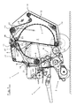
- FIG. 1 a machine 1 according to the invention for picking and pressing of agricultural crop to roll-shaped bale is shown.
- a receiving device 2 collects crop from the ground and forwards it into a winding chamber 3.
- a drive and control unit 4 provides opportunities for coupling a driven from the tractor vehicle drive shaft.
- bale forming device 7 In the winding chamber 3 of Erntegutballen is formed by the fact that through the inlet opening 6 in the winding chamber 3 transported crop is set by means of a bale forming device 7 in rotation and attaches the newly added material according to the lateral surfaces of the forming Erntegutballens.
- bale forming device 7 In the FIG. 1 shown bale forming device 7 is divided into two endless circumferential sections 8, 12.
- the front portion 8 is driven by a drive roller 9 and runs in addition to this housing-fixed drive roller 9 via a further housing-fixed deflection 11.
- the rear portion 12 is driven by a drive roller 13 and also runs over the housing-fixed deflections fourteenth
- bale forming device 7 To a plant of the inner portions 8, 12 of the bale forming device to the forming To ensure crop bales, such as a hay bale, form a plurality of clamping arms 16, 17, 18, the bale forming device 7 flexibly adjustable and pressed against the crop bales.
- the clamping arm 16 is rotatably connected to a lever arm 19 and pivotable about an axis 21. At the end of the clamping arm 16 are two deflections 23 which are close to each other and thus ensure a common management of the two sections 8 and 12.
- the middle clamping arm 17 and the rear clamping arm 18 are in engagement with the slack side of the sections 8, 12 and are pivoted about pivot axes 27 and 28, wherein the slack side of the adjacent to the bale parts of the sections 8, 12 only due to Distinguish the driving moments applied to the latter and acting on the bale.
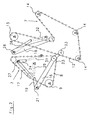
- the bale forming device 7 is during bale formation constantly in contact with the forming Erntegutballen and brings the necessary for a compaction of Erntegutballens pressing pressure, wherein the clamping arms 16, 17, 18 with the bale forming device 7 from the in FIG. 2 shown starting positions in the in FIG. 3 pivoting drawn end position. This end position depends on the respective Erntegutballen pressmesser and is variably adjustable. Obviously the shows in FIG. 3 illustrated arrangement of the clamping arms 16, 17, 18 with the respective sections 8, 12 an end position corresponding to a maximum diameter of a Erntegutballens.
- the cylinders 29, 31 and 32 connected to the lever arms 19, 24, 26 of the clamping arms 16, 17, 18 must firstly release the length of the bale forming device 7 required with increasing crop bale, but secondly the pressure necessary for a conventional compacting density of the crop bale ensure the bale forming device 7 on the Erntegutballen.
- the cylinder 29 is therefore designed as a pull cylinder to a pressing force in the direction of the bale exercise.
- the cylinder 31 is formed as a pressure cylinder, since he must keep the front portion 8 of the bale forming device 7 under tension.
- the cylinder 32 entrusted with the same task must likewise ensure a tensioning force of the bale forming device 7 and, because of its function which inverts the section 12 from the outside, is likewise designed as a pull cylinder.
- the cylinders 29, 31, 32 can also be arranged differently and / or pressurized. It is important here only that a part or a number of the cylinders 29, 31, 32 at least partially absorbs the amount of fluid of another part / number of cylinders.
- FIG. 4 shown in the direction of travel left and right of Erntegutballens each identical arrangements of cylinders 29, 31, 32 are provided, these are also controlled simultaneously and are in the FIG. 4 shown as cylinder pairs.
- the cylinders 29 are draw cylinders, that is to say they enter upon supply of fluid
- cylinders 31 extend around pressure cylinders which extend on supply of fluid
- cylinders 32 in turn about pull cylinders.
- a free return 34 and a valve arrangement for controlling the cylinders 29, 31, 32 are shown.
- the two cylinders 37 also shown serve the opening of the machine housing when unloading a finished Erntegutballens.
- the unlockable check valve 39 When opening the tailgate, which corresponds to the actuation of the cylinder 37, the unlockable check valve 39 is opened at the same time by the then applied to the input 33 system pressure. In this way, the pressure limiting valve 42 can be bypassed and the pressure in the clamping cylinders 29, 31, 32 drops to the adjustable pressure control valve 41 pressure level for the slip-free continued operation of the bale forming device 7, for example, 20 or 30 bar. After the bale has been ejected, the cylinders 29, 31 and 32 are in an intermediate position which is not shown here.
- the total acting on the Erntegutballen pressing pressure is adjusted by the pressure control valve 41 and the pressure relief valve 42, wherein, as already mentioned, the pressure control valve 41 controls the residual pressure in the system during the opening of the machine 1 for ejecting a Erntegutballens and the pressure relief valve 42 to the difference between the residual pressure is set to prevent slippage between drive lug and bale forming device 7 during opening and the desired pressing pressure.
Landscapes
- Life Sciences & Earth Sciences (AREA)
- Environmental Sciences (AREA)
- Storage Of Harvested Produce (AREA)
- Soil Working Implements (AREA)
- Sowing (AREA)
- Combines (AREA)
Description
- Die Erfindung betrifft eine Maschine zum Aufnehmen und Pressen von landwirtschaftlichem Erntegut zu rollenförmigen Ballen gemäß dem Oberbegriff des Patentanspruchs 1.
- In der
DE 40 12 738 C1 ist beispielsweise eine Maschine zum Aufnehmen und Pressen von landwirtschaftlichem Erntegut beschrieben, die dergestalt ausgebildet ist, dass eine Wickelkammer zur Bildung von rollenförmigen Erntegutballen von einem flexiblen Ballenförderer gebildet ist, welcher von mehreren Spannzylindern mit einer Spannkraft beaufschlagt ist. Zur Versorgung mit einem Druckmittel sind diese Spannzylinder über aufwändige Versorgungsleitungen und diverse Druckventile mit dem Hydrauliksystem einer landwirtschaftlichen Zug- und Antriebsmaschine verbindbar. Dies führt zu einer großen Anzahl von Hydraulikleitungen, die aufgrund der geforderten kurzen Zeitintervalle zum Spannen des Ballenförderers nach dem Ballenauswurf mit einem großen Leitungsquerschnitt ausgestattet sind. Diese Vielzahl von Hydraulikleitungen, die zusätzlich häufig ohne besondere Abdeckungen an den Außenwänden oder auch innen an den Maschinen verlegt werden, bringen zum einen eine erhöhte Störanfälligkeit für Leckagen oder Ölverlust, sowie einen hohen Montageaufwand und damit auch Kostenaufwand mit sich. Ein weiterer Mangel dieser Lösung besteht in dem erhöhten Austausch des Druckmittels zwischen der Zug- und Antriebsmaschine und der Maschine zum Pressen von landwirtschaftlichem Erntegut, welcher zu einer nicht notwendigen Erwärmung des Druckmittels führt. - Es ist daher Aufgabe der vorliegenden Erfindung den baulichen Aufwand für die Herstellung einer gattungsgemäßen Maschine zu verringern bzw. eine gattungsgemäße Maschine zu verbessern.
- Die Aufgabe wird durch eine gattungsgemäße Maschine gelöst, die sich dadurch auszeichnet, dass während des Betriebs eine erste Anzahl Zylinder eine Menge Fluid aufnimmt, die der von einer zweiten Anzahl der Zylinder abgegebenen Menge Fluid zumindest teilweise entspricht.
- Abhängig von der Anordnung der Zylinder innerhalb eines Maschinenaggregates, können beispielsweise Zug- und Druckzylinder bei dem Betrieb einer Ballenformeinrichtung auf unterschiedlichen Seiten eines Hebelarms angeordnet werden und so in identischer Richtung eine Kraft erzeugen. Ändert sich zum Beispiel aufgrund eines wachsenden Erntegutballens die Lage einer mit direkt gekoppelt angesteuerten Zylindern betriebenen Ballenformeinrichtung, so wird diese nach außen gedrückt und auf die Zylinder Druck ausgeübt. Dadurch wird eine Teilmenge eines Fluids aus beispielsweise den auf Seiten der Zylinderkolbenstange angeschlossenen Zylindern verdrängt und zum Teil von den auf der Zylinderkopfseite angeschlossenen Zylindern aufgenommen. Damit werden aufgrund der nun kleineren Menge Fluid, die im Rest des System strömt, kleiner ausgelegte Leitungen als im Stand der Technik benötigt. Alternativ können die zu transportierenden Fluidmengen schneller im System bewegt werden, was die gattungsgemäße Maschine weiter verbessert. Des weiteren wird der bauliche Aufwand für die Druckleitungen verringert, da die untereinander gekoppelten Zylinder zusammen beispielsweise nur an eine einzige Leitung anschließbar sind.
- Der Fluidkreislauf mit den Zylindern kann vorteilhafterweise auch dergestalt ausgebildet sein, dass die von einem Teil der Zylinder abgegebene Menge Fluid komplett von einem anderen Teil der Zylinder aufgenommen wird, so dass sich der bauliche Aufwand weiter verringert. Entsprechend müssen weniger Leitungen an dem Gehäuse einer erfindungsgemäßen Maschine angebracht werden, was Störanfälligkeit und Kosten reduziert.
- Weitere Vorteile und Einzelheiten ergeben sich aus den Unteransprüchen sowie den nachfolgend beschriebenen schematischen Zeichnungen einer erfindungsgemäßen Maschine. In den Zeichnungen zeigt:
- Figur 1:
- eine erfindungsgemäße Maschine mit einer von Zylindern kraftbeaufschlagbaren Ballenformeinrichtung,
- Figur 2:
- eine mit Zylindern versehene Baugruppe in einer ersten Position,
- Figur 3:
- den Gegenstand nach
Figur 2 in einer weiteren Position, - Figur 4:
- einen Schaltplan zum Betrieb des in den
Figuren 2 und3 dargestellten Maschinenaggregates. - In der
Figur 1 ist eine erfindungsgemäße Maschine 1 zum Aufnehmen und Pressen von landwirtschaftlichem Erntegut zu rollenförmigen Ballen dargestellt. Für die Erstellung eines hier nicht näher dargestellten Erntegutballens ist eine Mehrzahl von Maschinenaggregaten vorgesehen. Eine Aufnahmevorrichtung 2 sammelt Erntegut vom Boden auf und leitet es in eine Wickelkammer 3 weiter. Ein Antriebs- und Steuerungsaggregat 4 bietet Kopplungsmöglichkeiten für eine vom Schlepperfahrzeug aus betriebene Antriebswelle. - In der Wickelkammer 3 wird der Erntegutballen dadurch geformt, dass durch die Einlassöffnung 6 in die Wickelkammer 3 transportiertes Erntegut mit Hilfe einer Ballenformeinrichtung 7 in Rotation versetzt wird und sich das neu hinzugekommene Material entsprechend an den Mantelflächen des sich bildenden Erntegutballens anlagert. Die in
Figur 1 dargestellte Ballenformeinrichtung 7 ist in zwei endlos umlaufende Abschnitte 8, 12 eingeteilt. Der vordere Abschnitt 8 wird von einer Antriebsrolle 9 angetrieben und läuft zusätzlich zu dieser gehäusefesten Antriebsrolle 9 über eine weitere gehäusefeste Umlenkung 11. In ähnlicher Art und Weise ist der hintere Abschnitt 12 von einer Antriebsrolle 13 angetrieben und läuft ebenfalls über gehäusefeste Umlenkungen 14. - Um eine Anlage der inneren Abschnitte 8, 12 der Ballenformeinrichtung an dem sich bildenden Erntegutballen, beispielsweise einem Heuballen zu gewährleisten, bilden mehrere Spannarme 16, 17, 18 die Ballenformeinrichtung 7 flexibel anpassbar und an den Erntegutballen anpressbar aus.
- Der Spannarm 16 ist mit einem Hebelarm 19 drehfest verbunden und um eine Achse 21 verschwenkbar. Am Ende des Spannarms 16 befinden sich zwei Umlenkungen 23, die dicht beieinander liegen und somit eine gemeinsame Führung der beiden Abschnitte 8 und 12 gewährleisten.
- Der mittlere Spannarm 17 und der hintere Spannarm 18 befinden sich in Eingriff mit den Leertrums der Abschnitte 8, 12 und werden um Schwenkachsen 27 bzw. 28 geschwenkt, wobei sich die Leertrums von den an dem Ballen anliegenden Teilen der Abschnitte 8, 12 lediglich aufgrund der an letzteren anliegenden und auf den Ballen wirkenden Antriebsmomente unterscheiden.
- Die Ballenformeinrichtung 7 befindet sich während der Ballenbildung ständig in Anlage mit dem sich bildenden Erntegutballen und bringt den für eine Verdichtung des Erntegutballens notwendigen Pressdruck auf, wobei die Spannarme 16, 17, 18 mit der Ballenformeinrichtung 7 aus der in
Figur 2 gezeigten Ausgangspositionen in die inFigur 3 gezeichnete Endposition verschwenken. Diese Endposition ist abhängig vom jeweiligen Erntegutballendurchmesser und ist variabel einstellbar. Ersichtlich zeigt die inFigur 3 abgebildete Anordnung der Spannarme 16, 17, 18 mit den jeweiligen Abschnitten 8, 12 eine Endposition, die einem Maximaldurchmesser eines Erntegutballens entspricht. - Die mit den Hebelarmen 19, 24, 26 der Spannarme 16, 17, 18 verbundenen Zylinder 29, 31 und 32 müssen zum einen die bei größer werdendem Erntegutballen benötigte Länge der Ballenformeinrichtung 7 freigeben, zum anderen aber den für eine übliche Pressdichte des Erntegutballens notwendigen Druck der Ballenformeinrichtung 7 auf den Erntegutballen gewährleisten. Der Zylinder 29 ist daher als Zugzylinder ausgebildet, um eine Presskraft in Richtung des Ballens auszuüben. Im Gegensatz dazu ist der Zylinder 31 als Druckzylinder ausgebildet, da er den vorderen Abschnitt 8 der Ballenformeinrichtung 7 unter Spannung halten muss. Der mit der gleichen Aufgabe betraute Zylinder 32 muss ebenfalls eine Spannkraft der Ballenformeinrichtung 7 gewährleisten und ist aufgrund seiner den Abschnitt 12 von außen einstülpenden Funktion ebenfalls als Zugzylinder ausgebildet.
- Mit wachsendem Ballen fährt Zylinder 29, der auf der Kolbenstangenseite angesteuert ist, aus und gibt entsprechend der Verstellung des Kolbens eine bestimmte Menge Fluid ab. Ebenso fährt mit größer werdendem Erntegutballen der Zylinder 32 aus, der ebenfalls auf der Kolbenstangenseite mit einem Druckleitungsanschluss versehen ist, und gibt entsprechend Fluid ab. Die von den beiden Zylindern 29 und 32 abgegebene Menge Fluid wird bei diesem Ausführungsbeispiel zumindest teilweise von dem Zylinder 31 aufgenommen, der für die Spannung des vorderen Wickelbodenabschnitts 8 zuständig ist und ebenfalls ausfahren muss. So ergibt sich nach und nach der in
Figur 3 dargestellte Extremzustand mit einem maximal großen Erntegutballen. - Es ist offensichtlich, dass je nach Ansteuerung der Hebelarme 19, 24 und 26 die Zylinder 29, 31, 32 auch anders angeordnet und/oder druckbeaufschlagt werden können. Wichtig ist hierbei lediglich, dass ein Teil bzw. eine Anzahl der Zylinder 29, 31, 32 zumindest teilweise die Menge Fluid eines anderen Teils / einer anderen Anzahl der Zylinder aufnimmt.
- Der in
Figur 4 dargestellte Schaltplan verdeutlicht die Ansteuerung der jeweiligen Zylinder 29, 31, 32. Da in Fahrtrichtung links und rechts des Erntegutballens jeweils identische Anordnungen von Zylindern 29, 31, 32 vorgesehen sind, werden diese auch gleichzeitig angesteuert und sind in derFigur 4 als Zylinderpaare dargestellt. Ersichtlich handelt es sich bei den Zylindern 29 um Zugzylinder, dass heißt sie fahren bei Zuführung von Fluid ein, bei den Zylindern 31 um Druckzylinder, die bei Zuführung von Fluid ausfahren, und bei den Zylindern 32 wiederum um Zugzylinder. Neben einem Druckanschluss 33 ist ein freier Rücklauf 34 sowie eine Ventilanordnung zur Steuerung der Zylinder 29, 31, 32 gezeigt. Die beiden ebenfalls dargestellten Zylinder 37 dienen der Öffnung des Maschinengehäuses beim Entladen eines fertigen Erntegutballens. - Beim Öffnen der Heckklappe, die der Betätigung der Zylinder 37 entspricht, wird gleichzeitig durch den dann am Eingang 33 anliegenden Systemdruck das entsperrbare Rückschlagventil 39 geöffnet. Hierdurch kann das Druckbegrenzungsventil 42 umgangen werden und der Druck in den Spannzylindern 29, 31, 32 sinkt auf das am Druckregelventil 41 einstellbare Druckniveau für den schlupffreien Weiterbetrieb der Ballenformeinrichtung 7, beispielsweise auf 20 oder 30 bar. Nachdem der Ballen ausgeworfen wurde, befinden sich die Zylinder 29, 31 und 32 in einer Zwischenstellung, die hier nicht gezeigt ist.
- Zum Schließen der Heckklappe wird der Druckanschluss 33 drucklos geschaltet und die Zylinder 37 geben ein Fluidvolumen ab, welches wegen der Drosselung 43, welche einen Staudruck erzeugt, zumindest teilweise in den Rest des Systems zurück fließt. Damit werden die Zylinder 29, 31 und 32 wieder in ihre Ausgangsposition gebracht. Gleichzeitig ist auch das Rückschlagventil 39 wieder gesperrt, so dass bei einem wachsenden Erntegutballen im wesentlichen sofort wieder der notwendige Pressdruck von der Ballenformeinrichtung ausgeübt werden kann. Der insgesamt auf den Erntegutballen wirkende Pressdruck wird durch das Druckregelventil 41 und das Druckbegrenzungsventil 42 eingestellt, wobei wie bereits erwähnt das Druckregelventil 41 den Restdruck im System während des Öffnens der Maschine 1 zum Auswerfen eines Erntegutballens regelt und das Druckbegrenzungsventil 42 auf die Differenz zwischen dem Restdruck zur Vermeidung von Schlupf zwischen Antriebstollen und Ballenformeinrichtung 7 während des Öffnens und dem gewünschten Pressdruck eingestellt ist.
Claims (5)
- Maschine zum Aufnehmen und Pressen von landwirtschaftlichem Erntegut, wie Heu, Stroh, Gras oder dgl., zu rollenförmigen Ballen, mit einem als Wickelkammer (3) mit Ballenformeinrichtung (7) ausgebildeten Maschinenaggregat, das zumindest einen schwenkbaren, über die Ballenformeinrichtung (7) auf einen Emtegutballen Druck ausübenden Spannarm (16,17,18) aufweist und mit einer Mehrzahl von mit einem Fluid befüllbaren Zylindern (29, 31, 32) versehen ist, dadurch gekennzeichnet, dass im Betrieb eine erste Anzahl der Zylinder (29, 31, 32) eine Menge Fluid aufnimmt, die der von einer zweiten Anzahl der Zylinder (29, 31, 32) abgegebenen Menge Fluid im Sinne eines Medienaustausches zumindest teilweise entspricht.
- Maschine nach Anspruch 1, dadurch gekennzeichnet, dass die Zylinder (29, 31, 32) Hydraulikzylinder (29, 31, 32) sind.
- Maschine nach einem der Ansprüche 1 oder 2, gekennzeichnet durch zumindest ein, einer zum Betrieb der Zylinder (29, 31, 32) vorgesehenen Steuervorrichtung zugehöriges Druckregelventil (41), welches den an den Zylindern (29, 31, 32) anliegenden Druck auf ein regelbares Maximum begrenzt.
- Maschine nach Anspruch 3, dadurch gekennzeichnet, dass über das Druckregelventil (41) bei vollem Druckspeicher (36) eine Verbindung zu einem Rücklauf (34) vorgesehen ist.
- Maschine nach einem der Ansprüche 1 bis 4, gekennzeichnet, durch einen Druckanschluss (33) für eine externe Fluidquelle.
Applications Claiming Priority (2)
| Application Number | Priority Date | Filing Date | Title |
|---|---|---|---|
| DE102004023698 | 2004-05-11 | ||
| DE102004023698A DE102004023698B3 (de) | 2004-05-11 | 2004-05-11 | Maschine zum Aufnehmen und Pressen von landwirtschaftlichem Erntegut |
Publications (2)
| Publication Number | Publication Date |
|---|---|
| EP1595440A1 EP1595440A1 (de) | 2005-11-16 |
| EP1595440B1 true EP1595440B1 (de) | 2008-03-26 |
Family
ID=34936204
Family Applications (1)
| Application Number | Title | Priority Date | Filing Date |
|---|---|---|---|
| EP05009889A Expired - Lifetime EP1595440B1 (de) | 2004-05-11 | 2005-05-06 | Maschine zum Aufnehmen und Pressen von landwirtschaftlichem Erntegut |
Country Status (3)
| Country | Link |
|---|---|
| EP (1) | EP1595440B1 (de) |
| AT (1) | ATE390044T1 (de) |
| DE (2) | DE102004023698B3 (de) |
Cited By (1)
| Publication number | Priority date | Publication date | Assignee | Title |
|---|---|---|---|---|
| EP4275479A1 (de) * | 2022-05-11 | 2023-11-15 | Usines Claas France S.A.S | Verfahren zum betreiben einer rundballenpresse sowie rundballenpresse |
Families Citing this family (1)
| Publication number | Priority date | Publication date | Assignee | Title |
|---|---|---|---|---|
| DE102023104878A1 (de) * | 2023-02-28 | 2024-08-29 | Pöttinger Landtechnik Gmbh | Ballenpresse |
Family Cites Families (5)
| Publication number | Priority date | Publication date | Assignee | Title |
|---|---|---|---|---|
| DE1276960B (de) * | 1965-07-07 | 1968-09-05 | Massey Ferguson Australia Ltd | Ballenpresse fuer Stroh, Heu od. dgl. |
| GB2232375B (en) * | 1989-06-08 | 1993-01-13 | Deere & Co | Machine for forming cylindrical bales of crop |
| DE4012738C1 (de) * | 1990-04-21 | 1991-05-23 | Krone Bernard Maschf Gmbh | Maschine zum Aufnehmen und Pressen von landwirtschaftlichem Erntegut |
| DE19718229A1 (de) * | 1997-04-30 | 1998-11-05 | Claas Usines France | Landwirtschaftliche Rundballenpresse |
| DE10141232A1 (de) * | 2001-08-23 | 2003-03-06 | Amazonen Werke Dreyer H | Sämaschine |
-
2004
- 2004-05-11 DE DE102004023698A patent/DE102004023698B3/de not_active Expired - Fee Related
-
2005
- 2005-05-06 DE DE502005003412T patent/DE502005003412D1/de not_active Expired - Lifetime
- 2005-05-06 EP EP05009889A patent/EP1595440B1/de not_active Expired - Lifetime
- 2005-05-06 AT AT05009889T patent/ATE390044T1/de active
Cited By (1)
| Publication number | Priority date | Publication date | Assignee | Title |
|---|---|---|---|---|
| EP4275479A1 (de) * | 2022-05-11 | 2023-11-15 | Usines Claas France S.A.S | Verfahren zum betreiben einer rundballenpresse sowie rundballenpresse |
Also Published As
| Publication number | Publication date |
|---|---|
| ATE390044T1 (de) | 2008-04-15 |
| DE102004023698B3 (de) | 2005-12-29 |
| DE502005003412D1 (de) | 2008-05-08 |
| EP1595440A1 (de) | 2005-11-16 |
Similar Documents
| Publication | Publication Date | Title |
|---|---|---|
| EP1008292B1 (de) | Verfahren und Vorrichtung zum Herstellen von hochverdichteten Rundballen aus landwirtschaftlichen Erntegütern | |
| DE69607969T4 (de) | Rundballenpresse mit veränderlichem pressraum und ein pressraum mit veränderlicher geometrie um ballenkerne zu formen | |
| EP2243349B1 (de) | Rundballenpresse | |
| EP0940072B1 (de) | Presse mit einem Ballenpressraum, einem Kolben und einem hydraulischen Betätigungsglied | |
| DE212010000174U1 (de) | Ballenpresse zum Formen von Ballen ausFeldfrüchten | |
| DE10303201B4 (de) | Rundballenpresse für landwirtschaftliche Halmgüter | |
| EP2860397B1 (de) | Antriebssystem für hydraulisch angetriebene Arbeitsorgane einer Arbeitsmaschine | |
| EP0076502A2 (de) | Maschine zum Herstellen zylindrischer Ballen | |
| EP0102530A1 (de) | Verfahren zum Beseitigen von Überlastungen von Erntegutklumpen oder dgl. bei einer Anordnung zum Herstellen von zylindrischen Ballen aus Erntegut | |
| DE3004946A1 (de) | Schlepper | |
| EP0875136B1 (de) | Landwirtschaftliche Rundballenpresse | |
| DE2712878C2 (de) | Rollballenpresse für landwirtschaftliche Halmgüter mit hydraulischer Verriegelung | |
| DE69001152T2 (de) | Maschine zum formen zylindrischer ballen aus futterpflanzen. | |
| DE102010002733B4 (de) | Druckbegrenzungsventil für eine Rundballenpresse | |
| EP2016818B1 (de) | Hubwerk und Verfahren zum Ansteuern eines derartigen Hubwerks | |
| EP1595440B1 (de) | Maschine zum Aufnehmen und Pressen von landwirtschaftlichem Erntegut | |
| EP1595439B1 (de) | Maschine zum Aufnehmen und Pressen von landwirtschaftlichem Erntegut | |
| DE4012738C1 (de) | Maschine zum Aufnehmen und Pressen von landwirtschaftlichem Erntegut | |
| DE2517340A1 (de) | Rollballenpresse fuer landwirtschaftliche halmgueter mit zweiteiligem pressraumgehaeuse | |
| EP4129045A1 (de) | Rundballenpresse und verfahren zum öffnen einer auswurfklappe einer rundballenpresse | |
| DE2926817A1 (de) | Steuervorrichtung fuer ein schaltgetriebe im antrieb eines funktionsteils einer erntemaschine | |
| EP3437458A1 (de) | Einrichtung zur steuerung der auslassklappe einer ballenpresse, ballenpresse und verfahren | |
| DE102022113276A1 (de) | Landwirtschaftliche Ballenpresse mit einer Spanneinrichtung für einen Zugmitteltrieb | |
| DE102004023703B4 (de) | Maschine zum Aufnehmen und Pressen von landwirtschaftlichem Erntegut | |
| DE102022111818A1 (de) | Verfahren zum Betreiben einer Rundballenpresse sowie Rundballenpresse |
Legal Events
| Date | Code | Title | Description |
|---|---|---|---|
| PUAI | Public reference made under article 153(3) epc to a published international application that has entered the european phase |
Free format text: ORIGINAL CODE: 0009012 |
|
| AK | Designated contracting states |
Kind code of ref document: A1 Designated state(s): AT BE BG CH CY CZ DE DK EE ES FI FR GB GR HU IE IS IT LI LT LU MC NL PL PT RO SE SI SK TR |
|
| AX | Request for extension of the european patent |
Extension state: AL BA HR LV MK YU |
|
| 17P | Request for examination filed |
Effective date: 20060515 |
|
| AKX | Designation fees paid |
Designated state(s): AT BE BG CH CY CZ DE DK EE ES FI FR GB GR HU IE IS IT LI LT LU MC NL PL PT RO SE SI SK TR |
|
| 17Q | First examination report despatched |
Effective date: 20070228 |
|
| GRAP | Despatch of communication of intention to grant a patent |
Free format text: ORIGINAL CODE: EPIDOSNIGR1 |
|
| GRAS | Grant fee paid |
Free format text: ORIGINAL CODE: EPIDOSNIGR3 |
|
| GRAA | (expected) grant |
Free format text: ORIGINAL CODE: 0009210 |
|
| AK | Designated contracting states |
Kind code of ref document: B1 Designated state(s): AT BE BG CH CY CZ DE DK EE ES FI FR GB GR HU IE IS IT LI LT LU MC NL PL PT RO SE SI SK TR |
|
| REG | Reference to a national code |
Ref country code: GB Ref legal event code: FG4D Free format text: NOT ENGLISH |
|
| REG | Reference to a national code |
Ref country code: CH Ref legal event code: EP Ref country code: IE Ref legal event code: FG4D Free format text: LANGUAGE OF EP DOCUMENT: GERMAN |
|
| REF | Corresponds to: |
Ref document number: 502005003412 Country of ref document: DE Date of ref document: 20080508 Kind code of ref document: P |
|
| PG25 | Lapsed in a contracting state [announced via postgrant information from national office to epo] |
Ref country code: SI Free format text: LAPSE BECAUSE OF FAILURE TO SUBMIT A TRANSLATION OF THE DESCRIPTION OR TO PAY THE FEE WITHIN THE PRESCRIBED TIME-LIMIT Effective date: 20080326 Ref country code: PL Free format text: LAPSE BECAUSE OF FAILURE TO SUBMIT A TRANSLATION OF THE DESCRIPTION OR TO PAY THE FEE WITHIN THE PRESCRIBED TIME-LIMIT Effective date: 20080326 |
|
| PG25 | Lapsed in a contracting state [announced via postgrant information from national office to epo] |
Ref country code: CZ Free format text: LAPSE BECAUSE OF FAILURE TO SUBMIT A TRANSLATION OF THE DESCRIPTION OR TO PAY THE FEE WITHIN THE PRESCRIBED TIME-LIMIT Effective date: 20080326 Ref country code: PT Free format text: LAPSE BECAUSE OF FAILURE TO SUBMIT A TRANSLATION OF THE DESCRIPTION OR TO PAY THE FEE WITHIN THE PRESCRIBED TIME-LIMIT Effective date: 20080901 Ref country code: ES Free format text: LAPSE BECAUSE OF FAILURE TO SUBMIT A TRANSLATION OF THE DESCRIPTION OR TO PAY THE FEE WITHIN THE PRESCRIBED TIME-LIMIT Effective date: 20080707 Ref country code: SE Free format text: LAPSE BECAUSE OF FAILURE TO SUBMIT A TRANSLATION OF THE DESCRIPTION OR TO PAY THE FEE WITHIN THE PRESCRIBED TIME-LIMIT Effective date: 20080626 Ref country code: SK Free format text: LAPSE BECAUSE OF FAILURE TO SUBMIT A TRANSLATION OF THE DESCRIPTION OR TO PAY THE FEE WITHIN THE PRESCRIBED TIME-LIMIT Effective date: 20080326 |
|
| PG25 | Lapsed in a contracting state [announced via postgrant information from national office to epo] |
Ref country code: RO Free format text: LAPSE BECAUSE OF FAILURE TO SUBMIT A TRANSLATION OF THE DESCRIPTION OR TO PAY THE FEE WITHIN THE PRESCRIBED TIME-LIMIT Effective date: 20080326 |
|
| PG25 | Lapsed in a contracting state [announced via postgrant information from national office to epo] |
Ref country code: IS Free format text: LAPSE BECAUSE OF FAILURE TO SUBMIT A TRANSLATION OF THE DESCRIPTION OR TO PAY THE FEE WITHIN THE PRESCRIBED TIME-LIMIT Effective date: 20080726 Ref country code: MC Free format text: LAPSE BECAUSE OF NON-PAYMENT OF DUE FEES Effective date: 20080531 |
|
| ET | Fr: translation filed | ||
| PG25 | Lapsed in a contracting state [announced via postgrant information from national office to epo] |
Ref country code: EE Free format text: LAPSE BECAUSE OF FAILURE TO SUBMIT A TRANSLATION OF THE DESCRIPTION OR TO PAY THE FEE WITHIN THE PRESCRIBED TIME-LIMIT Effective date: 20080326 Ref country code: DK Free format text: LAPSE BECAUSE OF FAILURE TO SUBMIT A TRANSLATION OF THE DESCRIPTION OR TO PAY THE FEE WITHIN THE PRESCRIBED TIME-LIMIT Effective date: 20080326 Ref country code: LT Free format text: LAPSE BECAUSE OF FAILURE TO SUBMIT A TRANSLATION OF THE DESCRIPTION OR TO PAY THE FEE WITHIN THE PRESCRIBED TIME-LIMIT Effective date: 20080326 |
|
| PLBE | No opposition filed within time limit |
Free format text: ORIGINAL CODE: 0009261 |
|
| STAA | Information on the status of an ep patent application or granted ep patent |
Free format text: STATUS: NO OPPOSITION FILED WITHIN TIME LIMIT |
|
| 26N | No opposition filed |
Effective date: 20081230 |
|
| PG25 | Lapsed in a contracting state [announced via postgrant information from national office to epo] |
Ref country code: BG Free format text: LAPSE BECAUSE OF FAILURE TO SUBMIT A TRANSLATION OF THE DESCRIPTION OR TO PAY THE FEE WITHIN THE PRESCRIBED TIME-LIMIT Effective date: 20080626 |
|
| PG25 | Lapsed in a contracting state [announced via postgrant information from national office to epo] |
Ref country code: CY Free format text: LAPSE BECAUSE OF FAILURE TO SUBMIT A TRANSLATION OF THE DESCRIPTION OR TO PAY THE FEE WITHIN THE PRESCRIBED TIME-LIMIT Effective date: 20080326 |
|
| REG | Reference to a national code |
Ref country code: CH Ref legal event code: PL |
|
| GBPC | Gb: european patent ceased through non-payment of renewal fee |
Effective date: 20090506 |
|
| PG25 | Lapsed in a contracting state [announced via postgrant information from national office to epo] |
Ref country code: LI Free format text: LAPSE BECAUSE OF NON-PAYMENT OF DUE FEES Effective date: 20090531 Ref country code: CH Free format text: LAPSE BECAUSE OF NON-PAYMENT OF DUE FEES Effective date: 20090531 |
|
| PG25 | Lapsed in a contracting state [announced via postgrant information from national office to epo] |
Ref country code: GB Free format text: LAPSE BECAUSE OF NON-PAYMENT OF DUE FEES Effective date: 20090506 |
|
| PG25 | Lapsed in a contracting state [announced via postgrant information from national office to epo] |
Ref country code: HU Free format text: LAPSE BECAUSE OF FAILURE TO SUBMIT A TRANSLATION OF THE DESCRIPTION OR TO PAY THE FEE WITHIN THE PRESCRIBED TIME-LIMIT Effective date: 20080927 Ref country code: LU Free format text: LAPSE BECAUSE OF NON-PAYMENT OF DUE FEES Effective date: 20080506 |
|
| PG25 | Lapsed in a contracting state [announced via postgrant information from national office to epo] |
Ref country code: TR Free format text: LAPSE BECAUSE OF FAILURE TO SUBMIT A TRANSLATION OF THE DESCRIPTION OR TO PAY THE FEE WITHIN THE PRESCRIBED TIME-LIMIT Effective date: 20080326 |
|
| PG25 | Lapsed in a contracting state [announced via postgrant information from national office to epo] |
Ref country code: GR Free format text: LAPSE BECAUSE OF FAILURE TO SUBMIT A TRANSLATION OF THE DESCRIPTION OR TO PAY THE FEE WITHIN THE PRESCRIBED TIME-LIMIT Effective date: 20080627 |
|
| REG | Reference to a national code |
Ref country code: FR Ref legal event code: PLFP Year of fee payment: 12 |
|
| REG | Reference to a national code |
Ref country code: FR Ref legal event code: PLFP Year of fee payment: 13 |
|
| REG | Reference to a national code |
Ref country code: FR Ref legal event code: PLFP Year of fee payment: 14 |
|
| REG | Reference to a national code |
Ref country code: BE Ref legal event code: HC Owner name: MASCHINENFABRIK BERNARD KRONE GMBH & CO. KG; DE Free format text: DETAILS ASSIGNMENT: CHANGE OF OWNER(S), CHANGE OF OWNER(S) NAME Effective date: 20210209 |
|
| PGFP | Annual fee paid to national office [announced via postgrant information from national office to epo] |
Ref country code: NL Payment date: 20210519 Year of fee payment: 17 Ref country code: IT Payment date: 20210531 Year of fee payment: 17 Ref country code: FI Payment date: 20210518 Year of fee payment: 17 Ref country code: FR Payment date: 20210521 Year of fee payment: 17 |
|
| PGFP | Annual fee paid to national office [announced via postgrant information from national office to epo] |
Ref country code: IE Payment date: 20210519 Year of fee payment: 17 Ref country code: AT Payment date: 20210518 Year of fee payment: 17 Ref country code: BE Payment date: 20210519 Year of fee payment: 17 |
|
| REG | Reference to a national code |
Ref country code: DE Ref legal event code: R081 Ref document number: 502005003412 Country of ref document: DE Owner name: KRONE AGRICULTURE SE, DE Free format text: FORMER OWNER: MASCHINENFABRIK BERNARD KRONE GMBH, 48480 SPELLE, DE |
|
| REG | Reference to a national code |
Ref country code: FI Ref legal event code: PCE Owner name: KRONE AGRICULTURE SE |
|
| REG | Reference to a national code |
Ref country code: AT Ref legal event code: PC Ref document number: 390044 Country of ref document: AT Kind code of ref document: T Owner name: KRONE AGRICULTURE SE, DE Effective date: 20211022 |
|
| REG | Reference to a national code |
Ref country code: NL Ref legal event code: PD Owner name: KRONE AGRICULTURE SE; DE Free format text: DETAILS ASSIGNMENT: CHANGE OF OWNER(S), MERGE; FORMER OWNER NAME: MASCHINENFABRIK KRONE BETEILIGUNGS-GMBH Effective date: 20211126 Ref country code: NL Ref legal event code: HC Owner name: MASCHINENFABRIK KRONE BETEILIGUNGS-GMBH; DE Free format text: DETAILS ASSIGNMENT: CHANGE OF OWNER(S), CHANGE OF OWNER(S) NAME; FORMER OWNER NAME: MASCHINENFABRIK BERNARD KRONE GMBH Effective date: 20211126 |
|
| REG | Reference to a national code |
Ref country code: DE Ref legal event code: R084 Ref document number: 502005003412 Country of ref document: DE |
|
| REG | Reference to a national code |
Ref country code: NL Ref legal event code: MM Effective date: 20220601 |
|
| REG | Reference to a national code |
Ref country code: AT Ref legal event code: MM01 Ref document number: 390044 Country of ref document: AT Kind code of ref document: T Effective date: 20220506 |
|
| REG | Reference to a national code |
Ref country code: BE Ref legal event code: MM Effective date: 20220531 |
|
| PG25 | Lapsed in a contracting state [announced via postgrant information from national office to epo] |
Ref country code: FI Free format text: LAPSE BECAUSE OF NON-PAYMENT OF DUE FEES Effective date: 20220506 Ref country code: AT Free format text: LAPSE BECAUSE OF NON-PAYMENT OF DUE FEES Effective date: 20220506 |
|
| PG25 | Lapsed in a contracting state [announced via postgrant information from national office to epo] |
Ref country code: IE Free format text: LAPSE BECAUSE OF NON-PAYMENT OF DUE FEES Effective date: 20220506 Ref country code: FR Free format text: LAPSE BECAUSE OF NON-PAYMENT OF DUE FEES Effective date: 20220531 |
|
| PG25 | Lapsed in a contracting state [announced via postgrant information from national office to epo] |
Ref country code: BE Free format text: LAPSE BECAUSE OF NON-PAYMENT OF DUE FEES Effective date: 20220531 |
|
| P01 | Opt-out of the competence of the unified patent court (upc) registered |
Effective date: 20230517 |
|
| PG25 | Lapsed in a contracting state [announced via postgrant information from national office to epo] |
Ref country code: NL Free format text: LAPSE BECAUSE OF NON-PAYMENT OF DUE FEES Effective date: 20220601 |
|
| PG25 | Lapsed in a contracting state [announced via postgrant information from national office to epo] |
Ref country code: IT Free format text: LAPSE BECAUSE OF NON-PAYMENT OF DUE FEES Effective date: 20220506 |
|
| PGFP | Annual fee paid to national office [announced via postgrant information from national office to epo] |
Ref country code: DE Payment date: 20230519 Year of fee payment: 19 |
|
| REG | Reference to a national code |
Ref country code: DE Ref legal event code: R119 Ref document number: 502005003412 Country of ref document: DE |
|
| PG25 | Lapsed in a contracting state [announced via postgrant information from national office to epo] |
Ref country code: DE Free format text: LAPSE BECAUSE OF NON-PAYMENT OF DUE FEES Effective date: 20241203 |