EP2859936B1 - Appareil et procédé de contrôle de la pollution de l'air - Google Patents
Appareil et procédé de contrôle de la pollution de l'air Download PDFInfo
- Publication number
- EP2859936B1 EP2859936B1 EP13793951.8A EP13793951A EP2859936B1 EP 2859936 B1 EP2859936 B1 EP 2859936B1 EP 13793951 A EP13793951 A EP 13793951A EP 2859936 B1 EP2859936 B1 EP 2859936B1
- Authority
- EP
- European Patent Office
- Prior art keywords
- unit
- flue gas
- desulfurization
- ppm
- denitration
- Prior art date
- Legal status (The legal status is an assumption and is not a legal conclusion. Google has not performed a legal analysis and makes no representation as to the accuracy of the status listed.)
- Active
Links
- 238000003915 air pollution Methods 0.000 title claims description 31
- 238000000034 method Methods 0.000 title claims description 11
- CURLTUGMZLYLDI-UHFFFAOYSA-N Carbon dioxide Chemical compound O=C=O CURLTUGMZLYLDI-UHFFFAOYSA-N 0.000 claims description 83
- UGFAIRIUMAVXCW-UHFFFAOYSA-N Carbon monoxide Chemical compound [O+]#[C-] UGFAIRIUMAVXCW-UHFFFAOYSA-N 0.000 claims description 62
- 238000006477 desulfuration reaction Methods 0.000 claims description 61
- 230000023556 desulfurization Effects 0.000 claims description 61
- 239000003546 flue gas Substances 0.000 claims description 60
- 229910002092 carbon dioxide Inorganic materials 0.000 claims description 51
- 239000002250 absorbent Substances 0.000 claims description 40
- 230000002745 absorbent Effects 0.000 claims description 40
- 239000007789 gas Substances 0.000 claims description 40
- 238000011084 recovery Methods 0.000 claims description 34
- 239000003513 alkali Substances 0.000 claims description 33
- 239000001569 carbon dioxide Substances 0.000 claims description 32
- MWUXSHHQAYIFBG-UHFFFAOYSA-N nitrogen oxide Inorganic materials O=[N] MWUXSHHQAYIFBG-UHFFFAOYSA-N 0.000 claims description 24
- LSNNMFCWUKXFEE-UHFFFAOYSA-N Sulfurous acid Chemical compound OS(O)=O LSNNMFCWUKXFEE-UHFFFAOYSA-N 0.000 claims description 22
- 238000001816 cooling Methods 0.000 claims description 17
- 229910052815 sulfur oxide Inorganic materials 0.000 claims description 11
- XTQHKBHJIVJGKJ-UHFFFAOYSA-N sulfur monoxide Chemical class S=O XTQHKBHJIVJGKJ-UHFFFAOYSA-N 0.000 claims description 10
- QGZKDVFQNNGYKY-UHFFFAOYSA-N Ammonia Chemical compound N QGZKDVFQNNGYKY-UHFFFAOYSA-N 0.000 claims description 6
- XLYOFNOQVPJJNP-UHFFFAOYSA-N water Substances O XLYOFNOQVPJJNP-UHFFFAOYSA-N 0.000 claims description 6
- 239000010440 gypsum Substances 0.000 claims description 4
- 229910052602 gypsum Inorganic materials 0.000 claims description 4
- 229910021529 ammonia Inorganic materials 0.000 claims description 3
- 239000007788 liquid Substances 0.000 claims 2
- 239000007800 oxidant agent Substances 0.000 claims 1
- LSNNMFCWUKXFEE-UHFFFAOYSA-L sulfite Chemical compound [O-]S([O-])=O LSNNMFCWUKXFEE-UHFFFAOYSA-L 0.000 claims 1
- JCXJVPUVTGWSNB-UHFFFAOYSA-N Nitrogen dioxide Chemical compound O=[N]=O JCXJVPUVTGWSNB-UHFFFAOYSA-N 0.000 description 79
- 238000009825 accumulation Methods 0.000 description 16
- HEMHJVSKTPXQMS-UHFFFAOYSA-M Sodium hydroxide Chemical compound [OH-].[Na+] HEMHJVSKTPXQMS-UHFFFAOYSA-M 0.000 description 15
- 238000010521 absorption reaction Methods 0.000 description 9
- 150000001412 amines Chemical class 0.000 description 7
- 230000015556 catabolic process Effects 0.000 description 6
- 239000000498 cooling water Substances 0.000 description 6
- 238000006731 degradation reaction Methods 0.000 description 6
- 238000005406 washing Methods 0.000 description 6
- 239000003795 chemical substances by application Substances 0.000 description 5
- 230000000694 effects Effects 0.000 description 4
- 238000004140 cleaning Methods 0.000 description 3
- 230000003647 oxidation Effects 0.000 description 3
- 238000007254 oxidation reaction Methods 0.000 description 3
- 239000000126 substance Substances 0.000 description 3
- 230000000052 comparative effect Effects 0.000 description 2
- 230000007423 decrease Effects 0.000 description 2
- 239000002803 fossil fuel Substances 0.000 description 2
- VNWKTOKETHGBQD-UHFFFAOYSA-N methane Chemical compound C VNWKTOKETHGBQD-UHFFFAOYSA-N 0.000 description 2
- 238000002203 pretreatment Methods 0.000 description 2
- MGWGWNFMUOTEHG-UHFFFAOYSA-N 4-(3,5-dimethylphenyl)-1,3-thiazol-2-amine Chemical compound CC1=CC(C)=CC(C=2N=C(N)SC=2)=C1 MGWGWNFMUOTEHG-UHFFFAOYSA-N 0.000 description 1
- 235000019738 Limestone Nutrition 0.000 description 1
- 229910002089 NOx Inorganic materials 0.000 description 1
- RAHZWNYVWXNFOC-UHFFFAOYSA-N Sulphur dioxide Chemical compound O=S=O RAHZWNYVWXNFOC-UHFFFAOYSA-N 0.000 description 1
- 239000006096 absorbing agent Substances 0.000 description 1
- -1 amine compound Chemical class 0.000 description 1
- 239000003245 coal Substances 0.000 description 1
- 238000002485 combustion reaction Methods 0.000 description 1
- 230000003247 decreasing effect Effects 0.000 description 1
- TXKMVPPZCYKFAC-UHFFFAOYSA-N disulfur monoxide Inorganic materials O=S=S TXKMVPPZCYKFAC-UHFFFAOYSA-N 0.000 description 1
- 229940079593 drug Drugs 0.000 description 1
- 239000003814 drug Substances 0.000 description 1
- 230000002401 inhibitory effect Effects 0.000 description 1
- 239000006028 limestone Substances 0.000 description 1
- 239000003595 mist Substances 0.000 description 1
- 239000003345 natural gas Substances 0.000 description 1
- 238000010248 power generation Methods 0.000 description 1
- 238000004904 shortening Methods 0.000 description 1
- 238000010792 warming Methods 0.000 description 1
Images


Classifications
-
- B—PERFORMING OPERATIONS; TRANSPORTING
- B01—PHYSICAL OR CHEMICAL PROCESSES OR APPARATUS IN GENERAL
- B01D—SEPARATION
- B01D53/00—Separation of gases or vapours; Recovering vapours of volatile solvents from gases; Chemical or biological purification of waste gases, e.g. engine exhaust gases, smoke, fumes, flue gases, aerosols
- B01D53/34—Chemical or biological purification of waste gases
- B01D53/46—Removing components of defined structure
- B01D53/60—Simultaneously removing sulfur oxides and nitrogen oxides
-
- B—PERFORMING OPERATIONS; TRANSPORTING
- B01—PHYSICAL OR CHEMICAL PROCESSES OR APPARATUS IN GENERAL
- B01D—SEPARATION
- B01D53/00—Separation of gases or vapours; Recovering vapours of volatile solvents from gases; Chemical or biological purification of waste gases, e.g. engine exhaust gases, smoke, fumes, flue gases, aerosols
- B01D53/34—Chemical or biological purification of waste gases
- B01D53/74—General processes for purification of waste gases; Apparatus or devices specially adapted therefor
- B01D53/77—Liquid phase processes
- B01D53/78—Liquid phase processes with gas-liquid contact
-
- B—PERFORMING OPERATIONS; TRANSPORTING
- B01—PHYSICAL OR CHEMICAL PROCESSES OR APPARATUS IN GENERAL
- B01D—SEPARATION
- B01D53/00—Separation of gases or vapours; Recovering vapours of volatile solvents from gases; Chemical or biological purification of waste gases, e.g. engine exhaust gases, smoke, fumes, flue gases, aerosols
- B01D53/34—Chemical or biological purification of waste gases
- B01D53/46—Removing components of defined structure
- B01D53/48—Sulfur compounds
- B01D53/50—Sulfur oxides
- B01D53/501—Sulfur oxides by treating the gases with a solution or a suspension of an alkali or earth-alkali or ammonium compound
- B01D53/504—Sulfur oxides by treating the gases with a solution or a suspension of an alkali or earth-alkali or ammonium compound characterised by a specific device
-
- B—PERFORMING OPERATIONS; TRANSPORTING
- B01—PHYSICAL OR CHEMICAL PROCESSES OR APPARATUS IN GENERAL
- B01D—SEPARATION
- B01D53/00—Separation of gases or vapours; Recovering vapours of volatile solvents from gases; Chemical or biological purification of waste gases, e.g. engine exhaust gases, smoke, fumes, flue gases, aerosols
- B01D53/34—Chemical or biological purification of waste gases
- B01D53/46—Removing components of defined structure
- B01D53/48—Sulfur compounds
- B01D53/50—Sulfur oxides
- B01D53/507—Sulfur oxides by treating the gases with other liquids
-
- B—PERFORMING OPERATIONS; TRANSPORTING
- B01—PHYSICAL OR CHEMICAL PROCESSES OR APPARATUS IN GENERAL
- B01D—SEPARATION
- B01D53/00—Separation of gases or vapours; Recovering vapours of volatile solvents from gases; Chemical or biological purification of waste gases, e.g. engine exhaust gases, smoke, fumes, flue gases, aerosols
- B01D53/34—Chemical or biological purification of waste gases
- B01D53/46—Removing components of defined structure
- B01D53/54—Nitrogen compounds
- B01D53/56—Nitrogen oxides
-
- B—PERFORMING OPERATIONS; TRANSPORTING
- B01—PHYSICAL OR CHEMICAL PROCESSES OR APPARATUS IN GENERAL
- B01D—SEPARATION
- B01D53/00—Separation of gases or vapours; Recovering vapours of volatile solvents from gases; Chemical or biological purification of waste gases, e.g. engine exhaust gases, smoke, fumes, flue gases, aerosols
- B01D53/34—Chemical or biological purification of waste gases
- B01D53/46—Removing components of defined structure
- B01D53/62—Carbon oxides
-
- B—PERFORMING OPERATIONS; TRANSPORTING
- B01—PHYSICAL OR CHEMICAL PROCESSES OR APPARATUS IN GENERAL
- B01D—SEPARATION
- B01D53/00—Separation of gases or vapours; Recovering vapours of volatile solvents from gases; Chemical or biological purification of waste gases, e.g. engine exhaust gases, smoke, fumes, flue gases, aerosols
- B01D53/34—Chemical or biological purification of waste gases
- B01D53/74—General processes for purification of waste gases; Apparatus or devices specially adapted therefor
- B01D53/75—Multi-step processes
-
- B—PERFORMING OPERATIONS; TRANSPORTING
- B01—PHYSICAL OR CHEMICAL PROCESSES OR APPARATUS IN GENERAL
- B01D—SEPARATION
- B01D2251/00—Reactants
- B01D2251/30—Alkali metal compounds
- B01D2251/304—Alkali metal compounds of sodium
-
- B—PERFORMING OPERATIONS; TRANSPORTING
- B01—PHYSICAL OR CHEMICAL PROCESSES OR APPARATUS IN GENERAL
- B01D—SEPARATION
- B01D2251/00—Reactants
- B01D2251/50—Inorganic acids
-
- B—PERFORMING OPERATIONS; TRANSPORTING
- B01—PHYSICAL OR CHEMICAL PROCESSES OR APPARATUS IN GENERAL
- B01D—SEPARATION
- B01D2258/00—Sources of waste gases
- B01D2258/02—Other waste gases
- B01D2258/0283—Flue gases
-
- B—PERFORMING OPERATIONS; TRANSPORTING
- B01—PHYSICAL OR CHEMICAL PROCESSES OR APPARATUS IN GENERAL
- B01D—SEPARATION
- B01D53/00—Separation of gases or vapours; Recovering vapours of volatile solvents from gases; Chemical or biological purification of waste gases, e.g. engine exhaust gases, smoke, fumes, flue gases, aerosols
- B01D53/34—Chemical or biological purification of waste gases
- B01D53/46—Removing components of defined structure
- B01D53/48—Sulfur compounds
- B01D53/50—Sulfur oxides
-
- Y—GENERAL TAGGING OF NEW TECHNOLOGICAL DEVELOPMENTS; GENERAL TAGGING OF CROSS-SECTIONAL TECHNOLOGIES SPANNING OVER SEVERAL SECTIONS OF THE IPC; TECHNICAL SUBJECTS COVERED BY FORMER USPC CROSS-REFERENCE ART COLLECTIONS [XRACs] AND DIGESTS
- Y02—TECHNOLOGIES OR APPLICATIONS FOR MITIGATION OR ADAPTATION AGAINST CLIMATE CHANGE
- Y02A—TECHNOLOGIES FOR ADAPTATION TO CLIMATE CHANGE
- Y02A50/00—TECHNOLOGIES FOR ADAPTATION TO CLIMATE CHANGE in human health protection, e.g. against extreme weather
- Y02A50/20—Air quality improvement or preservation, e.g. vehicle emission control or emission reduction by using catalytic converters
-
- Y—GENERAL TAGGING OF NEW TECHNOLOGICAL DEVELOPMENTS; GENERAL TAGGING OF CROSS-SECTIONAL TECHNOLOGIES SPANNING OVER SEVERAL SECTIONS OF THE IPC; TECHNICAL SUBJECTS COVERED BY FORMER USPC CROSS-REFERENCE ART COLLECTIONS [XRACs] AND DIGESTS
- Y02—TECHNOLOGIES OR APPLICATIONS FOR MITIGATION OR ADAPTATION AGAINST CLIMATE CHANGE
- Y02C—CAPTURE, STORAGE, SEQUESTRATION OR DISPOSAL OF GREENHOUSE GASES [GHG]
- Y02C20/00—Capture or disposal of greenhouse gases
- Y02C20/40—Capture or disposal of greenhouse gases of CO2
Definitions
- the present invention relates to an air pollution control apparatus and corresponding method in which degradation of a CO 2 absorbent in a carbon dioxide recovery unit is suppressed by a pre-treatment that removes nitrogen oxides and sulfur oxides in the flue gas.
- a source of generation of CO 2 extends to the various fields of activities where fossil fuel is combusted, and a demand to suppressing the discharge tends to be further strengthened.
- a method of removing and recovering CO 2 in a flue gas by bringing the flue gas of a boiler into contact with an amine-based absorbent has been extensively studied.
- Patent Literatures 1, 2 and 3 there has been a suggestion for reducing a SO 2 concentration in the flue gas from a coal combustion boiler and reducing a NO 2 concentration in a natural gas flue gas.
- Patent Literatures 1 and 2 there is a suggestion of performing an advanced desulfurization such that a sulfur oxide concentration becomes 1 ppm, but further reduction (for example, 0.1 ppm or less) in the SO 2 concentration has been required in recent years.
- Patent Literature 2 there is a suggestion for performing an advanced denitration such that the nitrogen dioxide concentration becomes 3 ppm, but a further reduction (for example, preferably, 0.2 ppm or less at the outlet) in the NO 2 concentration has been required in recent years.
- an object of the present invention is to provide an air pollution control apparatus and a method that are capable of significantly suppressing the degradation of the CO 2 absorbent by a pre-treatment of the flue gas.
- the air pollution control apparatus of the present invention it is possible to further remove NO 2 having an extremely low concentration (for example, 1 ppm or less) and SO 2 having an extremely low concentration (for example, 50 ppm or less) remaining in the flue gas, using an absorbent containing the sulfite, and to perform finish denitration and desulfurization up to 0.1 ppm or less.
- NO 2 having an extremely low concentration for example, 1 ppm or less
- SO 2 having an extremely low concentration for example, 50 ppm or less
- FIG. 1 is a schematic view of an air pollution control apparatus (not according to this invention).
- FIGS. 2 and 3 are schematic views of an air pollution control apparatus according to the first embodiment.
- an air pollution control apparatus 10A has a denitration unit 12 that removes nitrogen oxides from a flue gas 11A containing nitrogen oxides, sulfur oxides, and carbon dioxide, for example, discharged from a boiler B up to an extremely low concentration, a desulfurization unit 13 that is installed on a gas flow downstream side of the denitration unit 12 and removes the sulfur oxides in a flue gas 11B up to an extremely low concentration, a finish denitration and desulfurization unit 14 that is installed on the gas flow downstream side of the desulfurization unit 13 and performs finish denitration and desulfurization of NO 2 having the extremely low concentration and SO 2 having the extremely low concentration remaining in a flue gas 11C by an absorbent containing sulfite, and a carbon dioxide recovery unit 15 that is installed on the gas flow downstream side of the finish denitration and desulfurization unit 14, and removes and recovers carbon dioxide in a flue gas 11D.
- reference numeral 16 represents a purification unit 14 that removes nitrogen oxides from
- NO 2 in the flue gas 11A is denitrified up to an extremely low concentration (for example, 1 ppm or less) by the generally installed denitration unit 12.
- an ammonia denitration unit is adopted as the denitration unit 12.
- the SO 2 concentration in the flue gas 11B after denitration is desulfurized up to an extremely low concentration (for example, 50 ppm or less).
- an extremely low concentration for example, 50 ppm or less.
- a wet limestone and gypsum method is adopted as the desulfurization unit 13.
- the NO 2 concentration and the SO 2 concentration in the flue gas 11C is finish-removed to an extremely low concentration (0.1 ppm or less), using the absorbent containing the sulfite.
- the frequency of the cleaning operation can be reduced by about half.
- the SO 2 concentration is 1 ppm
- the SO 2 concentration is 0.1 ppm
- FIG. 5 is a graph illustrating a relation between pH and NO 2 absorptivity when the sulfite concentration in the absorbent is changed.
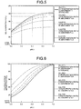
- FIG. 6 is a graph illustrating a relation between pH and the SO 2 equilibrium absorptivity when the sulfite concentration in the absorbent is changed.
- the standard sulfite concentration is 63 mmol/L.
- the standard sulfite concentration in the drawings is a sulfite concentration corresponding to a case where SO 2 absorbed by effluent of 5.5 t/hr from the finish denitration and desulfurization cooling tower is not oxidized at all, when the SO 2 concentration is 14 ppm in a case where an amount of the inlet flue gas is, for example, 700,000 Nm 3 /hr.
- pH and sulfite concentration is set.
- pH of the finish denitration and desulfurization unit 14 be pH 5.5 or higher, and preferably, be in a range of 5.5 to 7.0.
- a SO 2 alkali removal unit 18 is installed to remove remaining SO 2 therein to be a target SO 2 concentration of 0.1 ppm or less.
- alkali treatment agent it is possible to use, for example, sodium hydroxide (NaOH) or the like.
- the sulfite concentration may be reduced to improve the desulfurization performance.
- a gas cooling unit 19 may be installed on the gas flow downstream side of the SO 2 alkali removal unit 18.
- the concentration of NO 2 and SO 2 in a flue gas 11F introduced into the carbon dioxide recovery unit 15 can be set to 0.1 ppm or less, and it is possible to suppress the accumulation of the substance caused by NO 2 and SO 2 to the CO 2 absorbent.
- FIG. 4 is a schematic view of an air pollution control apparatus according to a second embodiment.
- the same components as in the first embodiment are denoted by the same reference numerals, and a detailed description thereof will not be provided.
- the finish denitration and desulfurization unit 14, the SO 2 alkali removal unit 18 installed above the gas flow downstream side thereof, and the gas cooling unit 19 installed above the downstream side of the SO 2 alkali removal unit 18 are integrally disposed within a finish denitration and desulfurization cooling tower 20.
- the finish denitration and desulfurization cooling tower 20 includes a SO 2 and NO 2 absorption part 21, a SO 2 alkali removal unit 31, and a cooling water washing part 41.
- a gas introduction line L 11 that introduces the flue gas 11C after the desulfurization treatment is provided in the bottom, and a gas discharge line L 12 that sends the flue gas 11F after the advanced denitration and desulfurization cooling treatment to the carbon dioxide recovery unit 15 from the tower top part is connected thereto.
- the SO 2 and NO 2 absorption part 21 performs a denitration and desulfurization by bringing the flue gas 11C into contact with an absorbent 23 containing the sulfite circulated by a circulation line L 1 , when introducing the introduced flue gas 11C upward from the bottom.
- a circulation pump P 1 and a cooling heat exchanger 22 are disposed in the circulation line L 1 .
- the flue gas 11D subjected to denitration and desulfurization is introduced into the SO 2 alkali removal unit 31, and when introducing the introduced flue gas 11D upward, desulfurization is performed by bringing the flue gas D into contact with an alkali absorbent 32 circulated by a circulation line L 2 .
- a circulation pump P 2 is disposed in the circulation line L 2 .
- An alkaline agent (NaOH) is supplied from a NaOH supply part 33.
- the desulfurization performance may be improved by supplying an air 34 as needed.
- a part of the alkali absorbent 32 is introduced into the SO 2 and NO 2 absorption part 21 by a branch line L 4 , and the desulfurization performance may be improved by supplying the alkaline agent to the absorbent 23 containing the sulfite.
- the desulfurized flue gas 11E is introduced into the cooling water washing part 41 again, and when introducing the introduced flue gas 11E upward, cleaning and cooling is performed by bringing the flue gas 11E into contact with a cooling water 43 circulated by a circulation line L 3 .
- a circulation pump P 3 and a cooling heat exchanger 42 are disposed in the circulation line L 3 .
- a known oxidation basin 51 is disposed in the effluent treatment line L 13 , and the oxidation treatment is accelerated here.
- an effluent 52 can be applied to, for example, the treating water of a limestone-gypsum method or the like.
- a gas cooling part demister is installed on the outlet side of the finish denitration and desulfurization cooling tower 20 to prevent entrainment of mist accompanied in the gas.
- the NO 2 concentration in the flue gas 11A discharged from the boiler B is approximately 6 to 15 ppm, and the SO 2 concentration is approximately 300 to 1,000 ppm
- the desulfurization unit 13 by passing through the denitration unit 12 the desulfurization unit 13, the NO 2 concentration in the flue gas 11C becomes approximately 0.5 to 1 ppm, and the SO 2 concentration becomes approximately 15 to 50 ppm.
- the flue gas 11C after the denitration and desulfurization treatment is introduced into the SO 2 and NO 2 absorption part 21 from the gas introduction line L 11 .
- the flue gas 11C comes into contact with the circulating absorbent 23 containing the sulfite, NO 2 and SO 2 in the gas are highly removed, the NO 2 concentration in the gas becomes 0.1 ppm or less, and the SO 2 concentration becomes 1.0 ppm or less.
- the flue gas 11D after the SO 2 and NO 2 absorption treatment is introduced into the SO 2 alkali removal unit 31 on the upper side thereof.
- SO 2 in the gas is highly removed, the NO 2 concentration in the gas becomes 0.1 ppm or less, and the SO 2 concentration becomes 0.1 ppm or less.
- the flue gas 11E after the SO 2 alkali removal treatment is introduced into the cooling water washing part 41 on the upper side thereof.
- the flue gas 11E comes into contact with the circulating cooling water 43, the alkali absorbent accompanied in the gas is removed, and the gas is cooled.
- the NO 2 concentration in the flue gas 11E becomes 0.1 ppm or less, and the SO 2 concentration becomes 0.1 ppm or less.
- Example 1 in the case of providing the finish denitration and desulfurization unit 14, NO 2 and SO 2 in the gas were highly removed, the NO 2 concentration in the gas became 0.1 ppm or less, and the SO 2 concentration became 1.0 ppm or less.
- the SO 2 accumulation ratio to the absorbent of the carbon dioxide recovery unit 15 at this time was 1. Furthermore, the NO 2 accumulation ratio to the absorbent of the carbon dioxide recovery unit 15 was 0.1. Furthermore, the amine quantity ratio accompanied in the purified gas 16 discharged from the carbon dioxide recovery unit 15 was 0.3.
- Example 2 in the case of providing the finish denitration and desulfurization unit 14 and the SO 2 alkali removal unit 18, NO 2 and SO 2 in the gas were highly removed, the NO 2 concentration in the gas became 0.1 ppm or less, and the SO 2 concentration became 0.1 ppm or less.
- the SO 2 accumulation ratio to the absorbent of the carbon dioxide recovery unit 15 at this time was 0.1. Furthermore, the NO 2 accumulation ratio to the absorbent of the carbon dioxide recovery unit 15 was 0.1. Furthermore, the amine quantity ratio accompanied in the purified gas 16 discharged from the carbon dioxide recovery unit 15 was 0.3.
- Example 2 since the SO 2 alkali removal unit 18 is further provided in Example 1, the SO 2 concentration was 1/10 (0.1 ppm or less) of Example 1, and the SO 2 accumulation ratio to the absorbent of the carbon dioxide recovery unit 15 was also 1/10 (0.1 ppm or less) of Example 1.
Landscapes
- Engineering & Computer Science (AREA)
- Chemical & Material Sciences (AREA)
- Environmental & Geological Engineering (AREA)
- Health & Medical Sciences (AREA)
- Biomedical Technology (AREA)
- Analytical Chemistry (AREA)
- General Chemical & Material Sciences (AREA)
- Oil, Petroleum & Natural Gas (AREA)
- Chemical Kinetics & Catalysis (AREA)
- Treating Waste Gases (AREA)
Claims (8)
- Dispositif pour réguler la pollution de l'air (10A ; 10B ; 10C) comprenant :une unité de dénitration (12) qui est configurée pour éliminer les oxydes d'azote dans un gaz d'échappement (11A) jusqu'à 1 ppm ou moins par de l'ammoniac, le gaz d'échappement (11A) étant déchargé d'une chaudière (B) et contenant des oxydes d'azote, des oxydes de soufre, et du dioxyde de carbone ;une unité de désulfuration par voie humide (13) qui est installée sur un côté aval du courant de gaz de l'unité de dénitration (12) et qui est configurée pour éliminer les oxydes de soufre dans le gaz d'échappement jusqu'à 50 ppm ou moins par un procédé au calcaire-gypse ;une unité de dénitration et de désulfuration de finition (14) qui est installée sur le côté aval du courant de gaz de l'unité de désulfuration par voie humide (13) et qui est configurée pour effectuer une dénitration et une désulfuration finales du NO2 et du SO2 restant dans le gaz d'échappement jusqu'à 0,1 ppm ou moins et 1,0 ppm ou moins, respectivement, par un liquide absorbant contenant du sulfite issu du SO2 dans le gaz d'échappement ;une unité d'élimination de SO2 par un alcali (18) qui est installée sur le côté aval du courant de gaz de l'unité de dénitration et de désulfuration de finition (14) et qui est configurée pour éliminer le SO2 résiduel dans le gaz d'échappement jusqu'à 0,1 ppm ou moins par un alcali ; etune unité de récupération de dioxyde de carbone (15) qui est installée sur le côté aval du courant de gaz de l'unité de dénitration et de désulfuration de finition (14) et qui est configurée pour éliminer et récupérer le dioxyde de carbone dans le gaz d'échappement par un absorbant de CO2,dans lequel l'unité de dénitration et de désulfuration de finition et l'unité d'élimination de SO2 par un alcali sont disposées entre l'unité de désulfuration par voie humide et l'unité de récupération de dioxyde de carbone.
- Dispositif pour réguler la pollution de l'air (10A ; 10B ; 10C) selon la revendication 1, comprenant en outre :une unité de refroidissement de gaz (19) qui est installée sur un côté aval du courant de gaz de l'unité d'élimination de SO2 par un alcali (18) pour refroidir le gaz d'échappement.
- Dispositif pour réguler la pollution de l'air (10A ; 10B ; 10C) selon la revendication 2, dans lequel l'unité de dénitration et de désulfuration de finition (14) et l'unité d'élimination de SO2 par un alcali (18) et l'unité de refroidissement de gaz (19) sont disposées solidairement dans une tour de refroidissement avec dénitration et désulfuration de finition (20).
- Dispositif pour réguler la pollution de l'air (10A ; 10B ; 10C) selon l'une quelconque des revendications 1 à 3, dans lequel l'unité d'élimination de SO2 par un alcali (18) est configurée pour introduire un agent oxydant.
- Dispositif pour réguler la pollution de l'air (10A ; 10B ; 10C) selon l'une quelconque des revendications 1 à 4, dans lequel l'unité de dénitration et de désulfuration de finition (14) est configurée pour introduire l'eau en excès de l'unité d'élimination de SO2 par un alcali (18).
- Dispositif pour réguler la pollution de l'air (10A ; 10B ; 10C) selon l'une quelconque des revendications 2 à 5, dans lequel l'unité d'élimination de SO2 par un alcali (18) est configurée pour introduire l'eau en excès de l'unité de refroidissement de gaz (19) .
- Procédé pour réguler la pollution de l'air comprenant :l'élimination d'oxydes d'azote dans un gaz d'échappement jusqu'à 1 ppm ou moins par de l'ammoniac dans une unité de dénitration, le gaz d'échappement étant déchargé d'une chaudière et contenant des oxydes d'azote, des oxydes de soufre, et du dioxyde de carbone ;l'élimination des oxydes de soufre dans le gaz d'échappement jusqu'à 50 ppm ou moins par un procédé au calcaire-gypse dans une unité de désulfuration par voie humide ;la mise en œuvre d'une dénitration et d'une désulfuration de finition du NO2 et du SO2 restant dans le gaz d'échappement jusqu'à 0,1 ppm ou moins et 1,0 ppm ou moins, respectivement, par un liquide absorbant contenant du sulfite issu du SO2 dans le gaz d'échappement dans une unité de dénitration et de désulfuration de finition ;l'élimination du SO2 résiduel dans le gaz d'échappement jusqu'à 0,1 ppm ou moins par un alcali dans une unité d'élimination de SO2 par un alcali ; etl'élimination et la récupération du dioxyde de carbone par un absorbant de CO2 dans le gaz d'échappement dans une unité de récupération de dioxyde de carbone.
- Procédé pour réguler la pollution de l'air selon la revendication 7, dans lequel la dénitration et la désulfuration de finition sont effectuées par augmentation de la concentration de sulfite pour mettre l'accent sur l'élimination du NO2 aux dépens de l'élimination du SO2 dans le gaz d'échappement.
Applications Claiming Priority (2)
| Application Number | Priority Date | Filing Date | Title |
|---|---|---|---|
| JP2012119786A JP6057545B2 (ja) | 2012-05-25 | 2012-05-25 | 排ガス処理装置 |
| PCT/JP2013/063828 WO2013176060A1 (fr) | 2012-05-25 | 2013-05-17 | Dispositif de traitement de gaz de décharge |
Publications (3)
| Publication Number | Publication Date |
|---|---|
| EP2859936A1 EP2859936A1 (fr) | 2015-04-15 |
| EP2859936A4 EP2859936A4 (fr) | 2016-03-09 |
| EP2859936B1 true EP2859936B1 (fr) | 2021-08-25 |
Family
ID=49623754
Family Applications (1)
| Application Number | Title | Priority Date | Filing Date |
|---|---|---|---|
| EP13793951.8A Active EP2859936B1 (fr) | 2012-05-25 | 2013-05-17 | Appareil et procédé de contrôle de la pollution de l'air |
Country Status (6)
| Country | Link |
|---|---|
| US (1) | US9789438B2 (fr) |
| EP (1) | EP2859936B1 (fr) |
| JP (1) | JP6057545B2 (fr) |
| AU (1) | AU2013264029B2 (fr) |
| CA (1) | CA2877611C (fr) |
| WO (1) | WO2013176060A1 (fr) |
Families Citing this family (12)
| Publication number | Priority date | Publication date | Assignee | Title |
|---|---|---|---|---|
| CN105561769B (zh) * | 2014-10-17 | 2019-05-21 | 华东理工大学 | 盐强化双氧水溶液氧化no的脱硝装置及方法 |
| CN105169917A (zh) * | 2015-09-26 | 2015-12-23 | 国网河南省电力公司电力科学研究院 | 一种基于氨氮摩尔比检测及调控的sncr-scr联合脱硝系统和方法 |
| CN105879643B (zh) * | 2016-05-28 | 2018-06-15 | 广东世纪青山镍业有限公司 | 一种镁法烟气脱硫方法 |
| CN107648965A (zh) * | 2016-07-25 | 2018-02-02 | 庄建中 | 一种燃烧垃圾的烟气综合净化工艺与设备 |
| CN106178893A (zh) * | 2016-08-25 | 2016-12-07 | 上海甘澍环境科技有限公司 | 一种碱液吸收塔及使用其对烟气进行湿法脱硝的方法 |
| JP6634395B2 (ja) | 2017-01-24 | 2020-01-22 | 三菱重工エンジニアリング株式会社 | 排ガス処理装置及びそれを用いたco2回収装置 |
| GB2554776B (en) * | 2017-03-13 | 2020-05-27 | Rocco Tulino Rosario | Particular liquid solution suitable to cool down and catch the pollutants that are inside the exhausts of diesel engines |
| CN109126457A (zh) * | 2018-09-07 | 2019-01-04 | 南通航泰船舶机械有限公司 | 一种船舶内燃机尾气脱硫脱硝方法 |
| CN109173637A (zh) * | 2018-10-30 | 2019-01-11 | 攀钢集团攀枝花钢铁研究院有限公司 | 低温烟气液相氧化脱硝的方法 |
| CN112403154A (zh) * | 2019-11-05 | 2021-02-26 | 中冶长天国际工程有限责任公司 | 一种烟气多污染物协同净化工艺及装置 |
| CN111450674B (zh) * | 2020-04-23 | 2022-02-08 | 自贡市东方联合机械配套有限公司 | 一种利用去除酸性氧化物排烟管道的尾气再氧化装置 |
| KR102378554B1 (ko) * | 2020-07-07 | 2022-03-24 | 한국조선해양 주식회사 | 선박용 배기가스 처리장치 및 이를 포함하는 선박 |
Citations (1)
| Publication number | Priority date | Publication date | Assignee | Title |
|---|---|---|---|---|
| WO2011152548A1 (fr) * | 2010-05-31 | 2011-12-08 | 三菱重工業株式会社 | Système et procédé de traitement de gaz d'échappement |
Family Cites Families (11)
| Publication number | Priority date | Publication date | Assignee | Title |
|---|---|---|---|---|
| JPS5284171A (en) * | 1977-02-08 | 1977-07-13 | Showa Denko Kk | Removal of nitrogen oxides and sulfur oxides in gas |
| WO1985003238A2 (fr) * | 1984-01-25 | 1985-08-01 | Hoelter Heinz | Procede d'extraction des oxydes d'azote et des oxydes de soufre, ainsi que, le cas echeant, d'autres elements nocifs des gaz de fumees provenant d'installations de combustion |
| JPH03293017A (ja) * | 1990-04-11 | 1991-12-24 | Mitsubishi Heavy Ind Ltd | 燃焼排ガスの処理方法 |
| JP3305001B2 (ja) * | 1992-03-03 | 2002-07-22 | 関西電力株式会社 | 燃焼排ガス中の二酸化炭素と硫黄酸化物を除去する方法 |
| US7628967B2 (en) * | 2002-10-01 | 2009-12-08 | Airborne Industrial Minerals, Inc. | Removal of Hg, NOx, and SOx with using oxidants and staged gas/liquid contact |
| JP4838489B2 (ja) * | 2003-07-25 | 2011-12-14 | 関西電力株式会社 | 二酸化窒素と二酸化炭素の除去方法及びその装置 |
| JP4216152B2 (ja) * | 2003-09-16 | 2009-01-28 | 関西電力株式会社 | 脱硫脱炭酸方法及びその装置 |
| US20090013868A1 (en) * | 2007-07-11 | 2009-01-15 | Arthur Darde | Process and apparatus for the separation of a gaseous mixture |
| US20110014106A1 (en) * | 2009-07-15 | 2011-01-20 | Fmc Corporation | COMBUSTION FLUE GAS SOx TREATMENT VIA DRY SORBENT INJECTION |
| EP2578298B1 (fr) * | 2010-05-31 | 2020-12-23 | Mitsubishi Heavy Industries Engineering, Ltd. | Procédé de traitement de gaz d'échappement |
| KR101266258B1 (ko) * | 2011-01-28 | 2013-05-22 | 한국에너지기술연구원 | 이산화탄소 포집공정용 연소배가스 처리장치 및 처리방법 |
-
2012
- 2012-05-25 JP JP2012119786A patent/JP6057545B2/ja active Active
-
2013
- 2013-05-17 CA CA2877611A patent/CA2877611C/fr active Active
- 2013-05-17 US US14/403,734 patent/US9789438B2/en active Active
- 2013-05-17 AU AU2013264029A patent/AU2013264029B2/en active Active
- 2013-05-17 EP EP13793951.8A patent/EP2859936B1/fr active Active
- 2013-05-17 WO PCT/JP2013/063828 patent/WO2013176060A1/fr active Application Filing
Patent Citations (1)
| Publication number | Priority date | Publication date | Assignee | Title |
|---|---|---|---|---|
| WO2011152548A1 (fr) * | 2010-05-31 | 2011-12-08 | 三菱重工業株式会社 | Système et procédé de traitement de gaz d'échappement |
Also Published As
| Publication number | Publication date |
|---|---|
| AU2013264029B2 (en) | 2016-05-12 |
| JP6057545B2 (ja) | 2017-01-11 |
| EP2859936A1 (fr) | 2015-04-15 |
| EP2859936A4 (fr) | 2016-03-09 |
| AU2013264029A1 (en) | 2015-01-22 |
| CA2877611A1 (fr) | 2013-11-28 |
| US20150125353A1 (en) | 2015-05-07 |
| WO2013176060A1 (fr) | 2013-11-28 |
| US9789438B2 (en) | 2017-10-17 |
| JP2013244454A (ja) | 2013-12-09 |
| CA2877611C (fr) | 2016-12-13 |
Similar Documents
| Publication | Publication Date | Title |
|---|---|---|
| EP2859936B1 (fr) | Appareil et procédé de contrôle de la pollution de l'air | |
| EP3685907B1 (fr) | Système de lutte contre la pollution de l'air et procédé de lutte contre la pollution de l'air | |
| EP2269713B1 (fr) | Procédé de récupération de CO2 | |
| EP2523742B1 (fr) | Procédé de lavage à l'eau pour un procédé de capture de dioxyde de carbone | |
| JP4959303B2 (ja) | 排気ガスの処理方法及び処理装置 | |
| US9216380B1 (en) | Ammonia stripper for a carbon capture system for reduction of energy consumption | |
| US10940431B2 (en) | Reclaiming method | |
| CN103505999B (zh) | 一种湿法脱硫脱硝的系统和方法 | |
| EP2537574B1 (fr) | Système de contrôle de la pollution de l'air et procédé de contrôle de la pollution de l'air | |
| US9381461B2 (en) | Air pollution control system and method | |
| EP2886183A1 (fr) | Dispositif de récupération de co2 et procédé de récupération de co2 | |
| WO2018139482A1 (fr) | Dispositif de traitement de gaz d'échappement et dispositif de récupération de co2 l'utilisant | |
| KR20130080476A (ko) | 산화황의 도입에 의해 오염된 아민계 용매의 가공 | |
| WO2013103990A2 (fr) | Système d'épuration des gaz muni d'un échangeur de chaleur à des fins de réduction de la consommation d'énergie du refroidisseur | |
| US20140105800A1 (en) | Method for processing a power plant flue gas | |
| EP2659948A1 (fr) | Système de récupération de co2 | |
| JP5881498B2 (ja) | 窒素酸化物および硫黄酸化物除去システム、窒素酸化物および硫黄酸化物除去方法、および二酸化炭素回収システム | |
| US9987587B2 (en) | Method and device for the treatment of a gas stream, in particular for the treatment of a natural gas stream | |
| KR102021935B1 (ko) | 액체주석을 이용한 질소산화물 및 황산화물 제거장치 및 제거방법 | |
| US20150139876A1 (en) | Amine-containing scrubbing solution with ozone and/or hydrogen peroxide for absorbing carbon dioxide | |
| KR20200114802A (ko) | 탈황공정수 재순환방법 | |
| KR20060071622A (ko) | 코크스 오븐 가스 중 유화수소의 선택적 흡수율 향상 방법 |
Legal Events
| Date | Code | Title | Description |
|---|---|---|---|
| PUAI | Public reference made under article 153(3) epc to a published international application that has entered the european phase |
Free format text: ORIGINAL CODE: 0009012 |
|
| 17P | Request for examination filed |
Effective date: 20141224 |
|
| AK | Designated contracting states |
Kind code of ref document: A1 Designated state(s): AL AT BE BG CH CY CZ DE DK EE ES FI FR GB GR HR HU IE IS IT LI LT LU LV MC MK MT NL NO PL PT RO RS SE SI SK SM TR |
|
| AX | Request for extension of the european patent |
Extension state: BA ME |
|
| DAX | Request for extension of the european patent (deleted) | ||
| RA4 | Supplementary search report drawn up and despatched (corrected) |
Effective date: 20160204 |
|
| RIC1 | Information provided on ipc code assigned before grant |
Ipc: B01D 53/56 20060101ALI20160129BHEP Ipc: B01D 53/75 20060101ALI20160129BHEP Ipc: B01D 53/60 20060101ALI20160129BHEP Ipc: B01D 53/77 20060101ALI20160129BHEP Ipc: B01D 53/62 20060101AFI20160129BHEP Ipc: B01D 53/74 20060101ALI20160129BHEP Ipc: B01D 53/34 20060101ALI20160129BHEP Ipc: B01D 53/50 20060101ALI20160129BHEP Ipc: B01D 53/94 20060101ALI20160129BHEP |
|
| STAA | Information on the status of an ep patent application or granted ep patent |
Free format text: STATUS: EXAMINATION IS IN PROGRESS |
|
| 17Q | First examination report despatched |
Effective date: 20180605 |
|
| RAP1 | Party data changed (applicant data changed or rights of an application transferred) |
Owner name: MITSUBISHI HEAVY INDUSTRIES ENGINEERING, LTD. |
|
| STAA | Information on the status of an ep patent application or granted ep patent |
Free format text: STATUS: EXAMINATION IS IN PROGRESS |
|
| GRAP | Despatch of communication of intention to grant a patent |
Free format text: ORIGINAL CODE: EPIDOSNIGR1 |
|
| STAA | Information on the status of an ep patent application or granted ep patent |
Free format text: STATUS: GRANT OF PATENT IS INTENDED |
|
| INTG | Intention to grant announced |
Effective date: 20210315 |
|
| GRAS | Grant fee paid |
Free format text: ORIGINAL CODE: EPIDOSNIGR3 |
|
| GRAA | (expected) grant |
Free format text: ORIGINAL CODE: 0009210 |
|
| STAA | Information on the status of an ep patent application or granted ep patent |
Free format text: STATUS: THE PATENT HAS BEEN GRANTED |
|
| AK | Designated contracting states |
Kind code of ref document: B1 Designated state(s): AL AT BE BG CH CY CZ DE DK EE ES FI FR GB GR HR HU IE IS IT LI LT LU LV MC MK MT NL NO PL PT RO RS SE SI SK SM TR |
|
| REG | Reference to a national code |
Ref country code: GB Ref legal event code: FG4D |
|
| REG | Reference to a national code |
Ref country code: CH Ref legal event code: EP |
|
| REG | Reference to a national code |
Ref country code: DE Ref legal event code: R096 Ref document number: 602013078977 Country of ref document: DE |
|
| REG | Reference to a national code |
Ref country code: IE Ref legal event code: FG4D Ref country code: AT Ref legal event code: REF Ref document number: 1423219 Country of ref document: AT Kind code of ref document: T Effective date: 20210915 |
|
| REG | Reference to a national code |
Ref country code: NL Ref legal event code: FP |
|
| REG | Reference to a national code |
Ref country code: LT Ref legal event code: MG9D |
|
| REG | Reference to a national code |
Ref country code: AT Ref legal event code: MK05 Ref document number: 1423219 Country of ref document: AT Kind code of ref document: T Effective date: 20210825 |
|
| PG25 | Lapsed in a contracting state [announced via postgrant information from national office to epo] |
Ref country code: RS Free format text: LAPSE BECAUSE OF FAILURE TO SUBMIT A TRANSLATION OF THE DESCRIPTION OR TO PAY THE FEE WITHIN THE PRESCRIBED TIME-LIMIT Effective date: 20210825 Ref country code: PT Free format text: LAPSE BECAUSE OF FAILURE TO SUBMIT A TRANSLATION OF THE DESCRIPTION OR TO PAY THE FEE WITHIN THE PRESCRIBED TIME-LIMIT Effective date: 20211227 Ref country code: ES Free format text: LAPSE BECAUSE OF FAILURE TO SUBMIT A TRANSLATION OF THE DESCRIPTION OR TO PAY THE FEE WITHIN THE PRESCRIBED TIME-LIMIT Effective date: 20210825 Ref country code: FI Free format text: LAPSE BECAUSE OF FAILURE TO SUBMIT A TRANSLATION OF THE DESCRIPTION OR TO PAY THE FEE WITHIN THE PRESCRIBED TIME-LIMIT Effective date: 20210825 Ref country code: LT Free format text: LAPSE BECAUSE OF FAILURE TO SUBMIT A TRANSLATION OF THE DESCRIPTION OR TO PAY THE FEE WITHIN THE PRESCRIBED TIME-LIMIT Effective date: 20210825 Ref country code: AT Free format text: LAPSE BECAUSE OF FAILURE TO SUBMIT A TRANSLATION OF THE DESCRIPTION OR TO PAY THE FEE WITHIN THE PRESCRIBED TIME-LIMIT Effective date: 20210825 Ref country code: BG Free format text: LAPSE BECAUSE OF FAILURE TO SUBMIT A TRANSLATION OF THE DESCRIPTION OR TO PAY THE FEE WITHIN THE PRESCRIBED TIME-LIMIT Effective date: 20211125 Ref country code: HR Free format text: LAPSE BECAUSE OF FAILURE TO SUBMIT A TRANSLATION OF THE DESCRIPTION OR TO PAY THE FEE WITHIN THE PRESCRIBED TIME-LIMIT Effective date: 20210825 Ref country code: SE Free format text: LAPSE BECAUSE OF FAILURE TO SUBMIT A TRANSLATION OF THE DESCRIPTION OR TO PAY THE FEE WITHIN THE PRESCRIBED TIME-LIMIT Effective date: 20210825 |
|
| REG | Reference to a national code |
Ref country code: NO Ref legal event code: T2 Effective date: 20210825 |
|
| PG25 | Lapsed in a contracting state [announced via postgrant information from national office to epo] |
Ref country code: PL Free format text: LAPSE BECAUSE OF FAILURE TO SUBMIT A TRANSLATION OF THE DESCRIPTION OR TO PAY THE FEE WITHIN THE PRESCRIBED TIME-LIMIT Effective date: 20210825 Ref country code: LV Free format text: LAPSE BECAUSE OF FAILURE TO SUBMIT A TRANSLATION OF THE DESCRIPTION OR TO PAY THE FEE WITHIN THE PRESCRIBED TIME-LIMIT Effective date: 20210825 Ref country code: GR Free format text: LAPSE BECAUSE OF FAILURE TO SUBMIT A TRANSLATION OF THE DESCRIPTION OR TO PAY THE FEE WITHIN THE PRESCRIBED TIME-LIMIT Effective date: 20211126 |
|
| PG25 | Lapsed in a contracting state [announced via postgrant information from national office to epo] |
Ref country code: DK Free format text: LAPSE BECAUSE OF FAILURE TO SUBMIT A TRANSLATION OF THE DESCRIPTION OR TO PAY THE FEE WITHIN THE PRESCRIBED TIME-LIMIT Effective date: 20210825 |
|
| REG | Reference to a national code |
Ref country code: DE Ref legal event code: R097 Ref document number: 602013078977 Country of ref document: DE |
|
| PG25 | Lapsed in a contracting state [announced via postgrant information from national office to epo] |
Ref country code: SM Free format text: LAPSE BECAUSE OF FAILURE TO SUBMIT A TRANSLATION OF THE DESCRIPTION OR TO PAY THE FEE WITHIN THE PRESCRIBED TIME-LIMIT Effective date: 20210825 Ref country code: SK Free format text: LAPSE BECAUSE OF FAILURE TO SUBMIT A TRANSLATION OF THE DESCRIPTION OR TO PAY THE FEE WITHIN THE PRESCRIBED TIME-LIMIT Effective date: 20210825 Ref country code: RO Free format text: LAPSE BECAUSE OF FAILURE TO SUBMIT A TRANSLATION OF THE DESCRIPTION OR TO PAY THE FEE WITHIN THE PRESCRIBED TIME-LIMIT Effective date: 20210825 Ref country code: EE Free format text: LAPSE BECAUSE OF FAILURE TO SUBMIT A TRANSLATION OF THE DESCRIPTION OR TO PAY THE FEE WITHIN THE PRESCRIBED TIME-LIMIT Effective date: 20210825 Ref country code: CZ Free format text: LAPSE BECAUSE OF FAILURE TO SUBMIT A TRANSLATION OF THE DESCRIPTION OR TO PAY THE FEE WITHIN THE PRESCRIBED TIME-LIMIT Effective date: 20210825 Ref country code: AL Free format text: LAPSE BECAUSE OF FAILURE TO SUBMIT A TRANSLATION OF THE DESCRIPTION OR TO PAY THE FEE WITHIN THE PRESCRIBED TIME-LIMIT Effective date: 20210825 |
|
| PLBE | No opposition filed within time limit |
Free format text: ORIGINAL CODE: 0009261 |
|
| STAA | Information on the status of an ep patent application or granted ep patent |
Free format text: STATUS: NO OPPOSITION FILED WITHIN TIME LIMIT |
|
| 26N | No opposition filed |
Effective date: 20220527 |
|
| PG25 | Lapsed in a contracting state [announced via postgrant information from national office to epo] |
Ref country code: SI Free format text: LAPSE BECAUSE OF FAILURE TO SUBMIT A TRANSLATION OF THE DESCRIPTION OR TO PAY THE FEE WITHIN THE PRESCRIBED TIME-LIMIT Effective date: 20210825 |
|
| REG | Reference to a national code |
Ref country code: CH Ref legal event code: PL |
|
| REG | Reference to a national code |
Ref country code: BE Ref legal event code: MM Effective date: 20220531 |
|
| PG25 | Lapsed in a contracting state [announced via postgrant information from national office to epo] |
Ref country code: MC Free format text: LAPSE BECAUSE OF FAILURE TO SUBMIT A TRANSLATION OF THE DESCRIPTION OR TO PAY THE FEE WITHIN THE PRESCRIBED TIME-LIMIT Effective date: 20210825 Ref country code: LU Free format text: LAPSE BECAUSE OF NON-PAYMENT OF DUE FEES Effective date: 20220517 Ref country code: LI Free format text: LAPSE BECAUSE OF NON-PAYMENT OF DUE FEES Effective date: 20220531 Ref country code: CH Free format text: LAPSE BECAUSE OF NON-PAYMENT OF DUE FEES Effective date: 20220531 |
|
| REG | Reference to a national code |
Ref country code: FR Ref legal event code: PLFP Year of fee payment: 11 |
|
| PG25 | Lapsed in a contracting state [announced via postgrant information from national office to epo] |
Ref country code: IE Free format text: LAPSE BECAUSE OF NON-PAYMENT OF DUE FEES Effective date: 20220517 |
|
| PG25 | Lapsed in a contracting state [announced via postgrant information from national office to epo] |
Ref country code: BE Free format text: LAPSE BECAUSE OF NON-PAYMENT OF DUE FEES Effective date: 20220531 |
|
| PGFP | Annual fee paid to national office [announced via postgrant information from national office to epo] |
Ref country code: GB Payment date: 20230330 Year of fee payment: 11 |
|
| P01 | Opt-out of the competence of the unified patent court (upc) registered |
Effective date: 20230522 |
|
| PGFP | Annual fee paid to national office [announced via postgrant information from national office to epo] |
Ref country code: NO Payment date: 20230510 Year of fee payment: 11 Ref country code: IT Payment date: 20230412 Year of fee payment: 11 Ref country code: FR Payment date: 20230411 Year of fee payment: 11 Ref country code: DE Payment date: 20230331 Year of fee payment: 11 |
|
| REG | Reference to a national code |
Ref country code: DE Ref legal event code: R081 Ref document number: 602013078977 Country of ref document: DE Owner name: MITSUBISHI HEAVY INDUSTRIES, LTD., JP Free format text: FORMER OWNER: MITSUBISHI HEAVY INDUSTRIES ENGINEERING, LTD., YOKOHAMA-SHI, KANAGAWA, JP |
|
| REG | Reference to a national code |
Ref country code: DE Ref legal event code: R081 Ref document number: 602013078977 Country of ref document: DE Owner name: MITSUBISHI HEAVY INDUSTRIES, LTD., JP Free format text: FORMER OWNER: MHI ENGINEERING, LTD., YOKOHAMA-SHI, KANAGAWA, JP |
|
| REG | Reference to a national code |
Ref country code: NL Ref legal event code: PD Owner name: MITSUBISHI HEAVY INDUSTRIES, LTD.; JP Free format text: DETAILS ASSIGNMENT: CHANGE OF OWNER(S), ASSIGNMENT; FORMER OWNER NAME: MHI ENGINEERING, LTD. Effective date: 20231206 Ref country code: NL Ref legal event code: HC Owner name: MHI ENGINEERING, LTD.; JP Free format text: DETAILS ASSIGNMENT: CHANGE OF OWNER(S), CHANGE OF OWNER(S) NAME; FORMER OWNER NAME: MITSUBISHI HEAVY INDUSTRIES ENGINEERING, LTD. Effective date: 20231206 |
|
| PG25 | Lapsed in a contracting state [announced via postgrant information from national office to epo] |
Ref country code: HU Free format text: LAPSE BECAUSE OF FAILURE TO SUBMIT A TRANSLATION OF THE DESCRIPTION OR TO PAY THE FEE WITHIN THE PRESCRIBED TIME-LIMIT; INVALID AB INITIO Effective date: 20130517 |
|
| PG25 | Lapsed in a contracting state [announced via postgrant information from national office to epo] |
Ref country code: MK Free format text: LAPSE BECAUSE OF FAILURE TO SUBMIT A TRANSLATION OF THE DESCRIPTION OR TO PAY THE FEE WITHIN THE PRESCRIBED TIME-LIMIT Effective date: 20210825 Ref country code: CY Free format text: LAPSE BECAUSE OF FAILURE TO SUBMIT A TRANSLATION OF THE DESCRIPTION OR TO PAY THE FEE WITHIN THE PRESCRIBED TIME-LIMIT Effective date: 20210825 |
|
| REG | Reference to a national code |
Ref country code: GB Ref legal event code: 732E Free format text: REGISTERED BETWEEN 20240404 AND 20240410 |
|
| PGFP | Annual fee paid to national office [announced via postgrant information from national office to epo] |
Ref country code: NL Payment date: 20240415 Year of fee payment: 12 |