EP2859598B1 - Thermoelektrisches modul und verfahren zum betrieb - Google Patents
Thermoelektrisches modul und verfahren zum betrieb Download PDFInfo
- Publication number
- EP2859598B1 EP2859598B1 EP13726479.2A EP13726479A EP2859598B1 EP 2859598 B1 EP2859598 B1 EP 2859598B1 EP 13726479 A EP13726479 A EP 13726479A EP 2859598 B1 EP2859598 B1 EP 2859598B1
- Authority
- EP
- European Patent Office
- Prior art keywords
- wall
- thermoelectric
- heat flow
- main heat
- flow direction
- Prior art date
- Legal status (The legal status is an assumption and is not a legal conclusion. Google has not performed a legal analysis and makes no representation as to the accuracy of the status listed.)
- Active
Links
- 238000000034 method Methods 0.000 title claims description 15
- 239000000463 material Substances 0.000 claims description 138
- 239000000945 filler Substances 0.000 claims description 21
- 230000008602 contraction Effects 0.000 claims description 14
- 230000035882 stress Effects 0.000 description 64
- 238000009413 insulation Methods 0.000 description 10
- 230000000875 corresponding effect Effects 0.000 description 9
- 238000013461 design Methods 0.000 description 5
- 230000008646 thermal stress Effects 0.000 description 5
- 230000008859 change Effects 0.000 description 4
- 230000001419 dependent effect Effects 0.000 description 4
- 239000007787 solid Substances 0.000 description 4
- 230000005678 Seebeck effect Effects 0.000 description 3
- 239000000919 ceramic Substances 0.000 description 3
- 238000006243 chemical reaction Methods 0.000 description 3
- 238000002485 combustion reaction Methods 0.000 description 3
- 238000010276 construction Methods 0.000 description 3
- 238000001816 cooling Methods 0.000 description 3
- 238000010292 electrical insulation Methods 0.000 description 3
- 230000005483 Hooke's law Effects 0.000 description 2
- 150000001875 compounds Chemical class 0.000 description 2
- 239000004020 conductor Substances 0.000 description 2
- 239000000498 cooling water Substances 0.000 description 2
- 238000011161 development Methods 0.000 description 2
- 230000005489 elastic deformation Effects 0.000 description 2
- 230000004907 flux Effects 0.000 description 2
- 239000007788 liquid Substances 0.000 description 2
- 229910018989 CoSb Inorganic materials 0.000 description 1
- 230000006835 compression Effects 0.000 description 1
- 238000007906 compression Methods 0.000 description 1
- 239000000110 cooling liquid Substances 0.000 description 1
- 230000007797 corrosion Effects 0.000 description 1
- 238000005260 corrosion Methods 0.000 description 1
- 230000006735 deficit Effects 0.000 description 1
- 230000006866 deterioration Effects 0.000 description 1
- 239000011810 insulating material Substances 0.000 description 1
- 230000003993 interaction Effects 0.000 description 1
- 239000010445 mica Substances 0.000 description 1
- 229910052618 mica group Inorganic materials 0.000 description 1
- 238000012544 monitoring process Methods 0.000 description 1
- 230000002093 peripheral effect Effects 0.000 description 1
- 238000003825 pressing Methods 0.000 description 1
- 230000002265 prevention Effects 0.000 description 1
- 230000002035 prolonged effect Effects 0.000 description 1
- 230000009467 reduction Effects 0.000 description 1
- 238000004904 shortening Methods 0.000 description 1
- 238000012546 transfer Methods 0.000 description 1
- XLYOFNOQVPJJNP-UHFFFAOYSA-N water Substances O XLYOFNOQVPJJNP-UHFFFAOYSA-N 0.000 description 1
Images


Classifications
-
- H—ELECTRICITY
- H10—SEMICONDUCTOR DEVICES; ELECTRIC SOLID-STATE DEVICES NOT OTHERWISE PROVIDED FOR
- H10N—ELECTRIC SOLID-STATE DEVICES NOT OTHERWISE PROVIDED FOR
- H10N10/00—Thermoelectric devices comprising a junction of dissimilar materials, i.e. devices exhibiting Seebeck or Peltier effects
- H10N10/10—Thermoelectric devices comprising a junction of dissimilar materials, i.e. devices exhibiting Seebeck or Peltier effects operating with only the Peltier or Seebeck effects
- H10N10/13—Thermoelectric devices comprising a junction of dissimilar materials, i.e. devices exhibiting Seebeck or Peltier effects operating with only the Peltier or Seebeck effects characterised by the heat-exchanging means at the junction
-
- H—ELECTRICITY
- H10—SEMICONDUCTOR DEVICES; ELECTRIC SOLID-STATE DEVICES NOT OTHERWISE PROVIDED FOR
- H10N—ELECTRIC SOLID-STATE DEVICES NOT OTHERWISE PROVIDED FOR
- H10N10/00—Thermoelectric devices comprising a junction of dissimilar materials, i.e. devices exhibiting Seebeck or Peltier effects
- H10N10/10—Thermoelectric devices comprising a junction of dissimilar materials, i.e. devices exhibiting Seebeck or Peltier effects operating with only the Peltier or Seebeck effects
- H10N10/17—Thermoelectric devices comprising a junction of dissimilar materials, i.e. devices exhibiting Seebeck or Peltier effects operating with only the Peltier or Seebeck effects characterised by the structure or configuration of the cell or thermocouple forming the device
-
- H—ELECTRICITY
- H10—SEMICONDUCTOR DEVICES; ELECTRIC SOLID-STATE DEVICES NOT OTHERWISE PROVIDED FOR
- H10N—ELECTRIC SOLID-STATE DEVICES NOT OTHERWISE PROVIDED FOR
- H10N10/00—Thermoelectric devices comprising a junction of dissimilar materials, i.e. devices exhibiting Seebeck or Peltier effects
- H10N10/10—Thermoelectric devices comprising a junction of dissimilar materials, i.e. devices exhibiting Seebeck or Peltier effects operating with only the Peltier or Seebeck effects
Definitions
- the present invention relates to a thermoelectric module and a method for operating a thermoelectric module.
- Thermoelectric modules can be used individually or in a plurality as a thermoelectric generator, which generates electrical energy from a temperature potential and the resulting heat flow. The generation of electrical energy is due to the so-called Seebeck effect.
- Thermoelectric modules are constructed of electrically interconnected p-doped and n-doped thermoelectric materials.
- the thermoelectric materials have a so-called hot side and an oppositely arranged cold side, via which they are each electrically conductively connected alternately with adjacently arranged further thermoelectric materials.
- the hot side is thermally conductively connected to a wall of a thermoelectric module, which is acted upon by a hot medium. Accordingly, the cold side of the thermoelectric material with another wall of the thermoelectric module in a thermally conductive compound, which is acted upon by a cold medium.
- thermoelectric generators are used in particular in motor vehicles, but also in other technical fields in which a temperature potential can be exploited by the arrangement of thermoelectric generators for generating electrical energy.
- thermoelectric generators With the use of thermoelectric generators, a drop in the efficiency with regard to the conversion of thermal energy into electrical energy over the term of the thermoelectric generator is frequently observed. This, occurring during operation wear, in particular be attributed to the fact that the connections between thermoelectric material and other connecting layers towards a first wall and / or to a second wall of a thermoelectric module increasingly deteriorate. These impairments of the heat-conducting and / or electrically conductive connections are in particular caused by the fact that the thermoelectric module is exposed to regularly changing or varying temperatures and temperature potentials. The thermoelectric module is loaded accordingly by changing thermal expansions and resulting thermal stresses. In addition, different thermal expansion coefficients in the individual bonding layers reinforce these stresses.
- thermoelectric module in which due to a temperature change occurring voltages can be compensated. This is accomplished by thermoelectric elements having an inclined top at one end (eg, cold side), the sloped top being connected to a correspondingly shaped surface of an electrical conductor.
- the thermoelectric elements are braced by a lateral spring means and slide on the inclined surface.
- thermoelectric module which has a uniform high efficiency in the conversion of thermal energy into electrical energy over a long period.
- a method for operating a thermoelectric module is to be given, which also allows a prolonged running time of a thermoelectric module, without the efficiency is increasingly reduced.
- thermoelectric module according to the features of patent claim 1 or claim 2 and by a method for operating a thermoelectric module according to claim 7.
- Advantageous embodiments of the invention are specified in the dependent formulated claims. It should be noted that the features listed individually in the claims can be combined with each other in any technologically meaningful manner and show further embodiments of the invention. The description, in particular in conjunction with the figures, further explains the invention and leads additional embodiments of the invention. It should be further noted that the embodiments described with respect to the thermoelectric module are equally applicable in a technically meaningful manner to the method for operating a thermoelectric module and vice versa.
- thermoelectric module has at least a first wall and an oppositely disposed second wall and interposed therebetween elements made of thermoelectric material, which are electrically conductively connected to each other. Further, a filler material is provided, by which all elements are spaced from each other.
- a main heat flow direction extends from a hot side formed by the first wall to the second wall. It is envisaged that during operation of the thermoelectric module, at least in a temperature range between 50 and 600 ° C [degrees Celsius] on the hot side, a second compressive stress acting on the elements in the main heat flow direction does not exceed at least a first limit voltage or at least a second limit voltage exceeds.
- the first limit voltage is a (temperature-dependent) property of the elements made of thermoelectric material, which, when exceeded, causes a transverse contraction of the thermoelectric material used.
- the second limit voltage is a (temperature-dependent) property of the elements made of thermoelectric material, which, if exceeded, causes a plastic deformation of the thermoelectric material used.
- thermoelectric material when the second threshold voltage is reached, a transverse contraction of the thermoelectric material has already begun.
- thermoelectric module has at least a first wall and an oppositely disposed second wall and interposed therebetween elements of thermoelectric material, wherein the thermoelectric materials are electrically conductively connected to each other. Furthermore, a filling material is provided, by which all elements are spaced from each other. A main heat flow direction extends from the first wall towards the second wall.
- thermoelectric module is clamped by at least one compressive force such that a first compressive stress transverse to the main heat flow direction, at least in a region in which a temperature potential between first wall and second wall is at least 50 Kelvin, in particular at least 200 Kelvin, at least 50% of a second compressive stress in the main heat flow direction is, in particular at least 75%, and preferably at least as large as the second compressive stress (greater than 100%).
- first compressive stress (and preferably also the second compressive stress) acts on a majority, preferably on all, elements within the thermoelectric module.
- thermoelectric modules in this case, in particular tubular thermoelectric modules or plate-shaped thermoelectric modules are mentioned, wherein in the tubular thermoelectric modules z.
- B. annular thermoelectric materials are used.
- the first wall is associated with a hot side of the thermoelectric module, which is thus acted upon by a hot medium (eg exhaust gas).
- the second wall of the thermoelectric module is associated with a cold side, which is acted upon by a cold medium (eg., Cooling water).
- a hot medium eg exhaust gas
- a cold medium eg., Cooling water
- Between hot medium and cold medium is in operation before a temperature potential, especially in one Range of 50 K [Kelvin] to 600 K.
- the thermoelectric materials have two opposite sides, facing the hot side or the cold side, so that over the thermoelectric material forms a temperature potential and correspondingly forms a main heat flow direction from the hot side to the cold side.
- thermoelectric module As a result of the Seebeck effect, an electric current is generated within the thermoelectric module from this temperature potential and through the alternately electrically conductive connection of the n-doped and p-doped thermoelectric materials.
- the basic structure of the electrical interconnection of such elements made of thermoelectric material is known to the expert, if necessary, further information on this can be found in the prior publications of the applicant.
- thermoelectric elements serves, on the one hand, in particular for the electrical insulation of the adjacent thermoelectric materials and / or on the other hand for thermal insulation between the hot side and the cold side, so that a large part of the heat flow is passed over the thermoelectric elements.
- thermoelectric elements serves, on the one hand, in particular for the electrical insulation of the adjacent thermoelectric materials and / or on the other hand for thermal insulation between the hot side and the cold side, so that a large part of the heat flow is passed over the thermoelectric elements.
- the filling material is intended, in particular, to space the adjacently arranged thermoelectric materials from one another or, in other words, to keep them at a (predetermined) distance during all operating conditions.
- the filling material is thus not formed by air or a vacuum, but by at least one solid which permanently fixes the position of the thermoelectric materials to one another.
- further components or connecting layers which fulfill specific tasks, such as prevention of corrosion, generating a solid (eg cohesive) connection, providing an electrical conductive layer, providing a heat-conducting layer, electrical insulation and / or thermal insulation.
- mica or a flameproof ceramic can be used as filler material.
- the ceramic is used as a ceramic hollow body.
- the filler can be used in the form of a double T-profile.
- the filling material is used in the form of a dimensionally stable construction, in particular in the form of a truss-like construction.
- the cavities provided therein are filled in particular with air, gas or vacuum.
- thermoelectric material due to the thermal stress due to the present temperature potential and in particular by the associated thermal stresses has an increased tendency to transverse contraction and / or creep or tends to plastic deformation, which in each case to a deterioration of the Connection between thermoelectric material and other connecting layers leads, in particular towards the first wall or towards the second wall.
- thermal stresses are in particular caused by the arrangement of the thermoelectric materials in a largely dimensionally stable thermoelectric module, so that the thermoelectric materials can expand only under tension.
- thermoelectric module is constructed such that at least in a temperature range between 50 ° C and 600 ° C [degrees Celsius] at the hot side, a second compressive stress acting on the elements in the main heat flow direction does not exceed a second limit voltage.
- a second threshold voltage is the voltage applied to the thermoelectric materials, which utilizes plastic deformation of the thermoelectric material used.
- the transverse contraction of the thermoelectric material can be reduced or prevented in particular by configuring the thermoelectric module such that at least in a temperature range between 50 ° C. and 600 ° C. [degrees Celsius] on the hot side, one acting on the elements in the main heat flow direction second compressive stress does not exceed a first limit voltage.
- a first limit voltage is the voltage acting on the thermoelectric materials, in which already uses an elastic deformation of the thermoelectric material used.
- the transverse contraction is a phenomenon of deformation of a solid at approximately constant volume. It describes the behavior of the solid under the influence of a tensile force or compressive force (here a second compressive stress).
- a tensile force or compressive force here a second compressive stress
- the body reacts with a change in length (here shortening in the main heat flow direction), perpendicular thereto (in the direction transverse to the main heat flow direction) with a reduction or increase in its diameter or its thickness (in this case expansion, ie enlargement of the Thickness of the thermoelectric material).
- the change in length in a uniaxial train can be determined in the linear-elastic range by the simplified Hooke's law. However, Hooke's law in its simplified form makes no statements about the change in thickness.
- the first limit voltage is (significantly) less than the second limit voltage.
- thermoelectric module in particular the material for the first wall and / or the second wall to the thermoelectric material and / or the filler material with respect to thermal expansion, heat conduction, strength to match accordingly.
- expansion elements may be provided which allow elastic deformation of the first wall and / or the second wall, so that the (second) compressive stress acting on the elements is minimized.
- the first and the second limit voltage are each in particular specific for the thermoelectric material used and in particular depending at least on the temperature of the thermoelectric material. Further, the first and second limit voltages are dependent on the stress applied to the thermoelectric material, which is opposite to the direction of expansion (in the case of the first / second limit voltage) or the direction of creep (in the case of the second limit voltage) of the thermoelectric material. In particular, this means that the first and second limit voltages of the thermoelectric material can be influenced (increased) when the first compressive stress acting on the thermoelectric materials is increased. This is done in particular self-regulating, z. B. in that the filling materials between the thermoelectric materials when heated expand more in the direction transverse to the main heat flow direction than the thermoelectric module as a whole.
- thermoelectric materials mentioned below have the following second limiting stresses at the temperatures mentioned and without further compressive stress (eg, in addition to the first compressive stress), which may be expected to result in plastic deformation if they are exceeded: Pb 2 Te 3 (n-doped): 100 N / mm 2 at room temperature 40 N / mm 2 at 300 ° C Pb 2 Te 3 (p-doped): no plastic deformation up to 300 ° C BiTe (n-doped or p-doped): 110 N / mm 2 at room temperature 30 N / mm 2 at 250 ° C CoSb 4 (n-doped or p-doped): no plastic deformation up to 300 ° C 300 N / mm 2 at 500 ° C
- the transverse contraction and / or the creep / plastic deformation can be reduced or prevented by applying at least one compressive force to the thermoelectric module, so that a first compressive stress acts on the elements transversely to the main heat flow direction
- a first compressive stress acts on the elements transversely to the main heat flow direction
- this first compressive stress is then at least 50% of a second compressive stress in the main heat flow direction.
- the second compressive stress is caused in particular by the gap-free arrangement of the thermoelectric materials in a direction from the first wall to the second wall, ie in the main heat flow direction.
- thermal expansion of the components of the thermoelectric module arranged between the first wall and the second wall occurs, so that a second compressive stress in the main heat flow direction arises or is increased.
- This second compressive stress counteracts the thermal expansion of the individual components in the main heat flow direction and, in particular with the thermoelectric material, leads to expansion (due to transverse contraction) and / or to a creep in a direction transverse to the main heat flow direction.
- the transverse contraction and / or the creep tendency can be surprisingly reduced or completely suppressed by applying at least one first compressive stress transversely to the main heat flow direction.
- first compressive stresses are to be provided so that this transverse contraction and / or this creeping tendency is reduced or completely prevented in all directions transversely to the main heat flow direction.
- thermoelectric module is directed to the fact that the filler at least in a temperature range of 50 ° C to 600 ° C has a larger thermal expansion coefficient than the thermoelectric material.
- the filling material is arranged at least in one direction transversely to the main heat flow direction between the thermoelectric materials such that the thermoelectric materials are supported against each other via the filling material (and optionally via further components or connecting layers), ie in particular are arranged without gaps in this direction relative to one another.
- the filler material thus fixes the thermoelectric materials in their respective positions relative to each other.
- thermoelectric module By designing the filling material with a larger coefficient of thermal expansion than the thermoelectric material, when the filling material and the other components in the thermoelectric module are heated, a compressive force or a compressive stress is generated in a direction transverse to the main heat flow direction (only during operation) or (significant ).
- a largely dimensionally stable design of the thermoelectric module in this direction is to be ensured transversely to the main heat flow direction.
- the pressure force then does not have to be of be applied externally to the thermoelectric module so that the compressive stress is formed accordingly within the thermoelectric module, so that most (or all) elements are acted upon by a sufficient compressive stress. Instead, this compressive stress can thus be generated between most (or all) elements by the filler in interaction with the thermoelectric materials.
- thermoelectric module is directed to the fact that the filler has a lower thermal conductivity [watt / (meter * Kelvin] than the thermoelectric material at least in a temperature range of 50 ° C. to 600 ° C.
- the value of the thermal conductivity of the Filling material at most 10% of the value of the thermoelectric material, preferably at most 1%.
- thermoelectric module provides that the filling material, viewed in at least one direction parallel to the main heat flow direction, does not completely fill a gap between the first wall and the second wall. It is particularly advantageous that the filler material fixes the position of the thermoelectric materials to each other, but at the same time not the entire side surface of the thermoelectric materials, which faces each of the adjacent arranged thermoelectric materials covered. In particular, at most 80%, preferably at most 50% and particularly preferably at most 20% of this side surface is subjected to a compressive stress by the filling material, which does not have to apply equally to all elements or thermoelectric materials of a single module. The compressive force or the compressive stress is transferred to the thermoelectric material via the filling material.
- the thermal insulation between the first wall and the second wall can be implemented in a particularly advantageous manner and the filling material must have this thermal insulating property does not necessarily meet.
- the filling material must have this thermal insulating property does not necessarily meet.
- air, a vacuum or other heat-insulating material may be used in addition to the filler material.
- thermoelectric module is directed to that on a cold side, a bracing device for generating the pressure force on the thermoelectric module is arranged in a direction transverse to the main heat flow direction.
- this arrangement comprises a z. B. connected to the second wall bracing device.
- This bracing device is in particular thermally insulated from the first wall.
- the bracing device may in particular be a mechanical or even hydraulic device. In particular, it is formed by a particularly rigid design of the cold side or the second wall, so that in the temperature range considered a (substantially constant or adapted) compressive force against the thermoelectric materials and the filler material can be generated starting from the bracing device.
- a bracing device is (additionally) provided on the first wall (hot side).
- the bracing device may in particular comprise an elastically deformable element which can initiate a correspondingly higher compressive stress into the thermoelectric module with greater deformation.
- a compression spring may be provided which, in the case of continuous expansion of the thermoelectric module, or in the case of expansion of the elements in one direction transversely to the main heat flow direction generates a correspondingly increasing compressive stress. This increasing compressive stress reduces or prevents elastic expansion and / or plastic deformation of the thermoelectric materials in a direction transverse to the main heat flow direction.
- thermoelectric module applies correspondingly to the method for operating a thermoelectric module and vice versa.
- the method described here according to the invention for operating the respectively inventive thermoelectric module is suitable.
- the generation of the temperature potential according to step a) comprises applying the first wall to a hot medium and applying the second wall to a cold medium.
- a hot medium for example, an exhaust gas or a liquid medium as a hot medium and z.
- a gaseous medium As a cold medium.
- Step b) comprises the application of at least one compressive force, which is applied in particular by a bracing device from the outside to the thermoelectric module and / or within the thermoelectric module z.
- B. can be generated by corresponding expansion coefficients of the thermoelectric material and the filling material.
- Ensuring the ratio of the compressive stresses according to step c) comprises, in particular, the corresponding structural design of the thermoelectric module even before the start of operation.
- the ensuring comprises the control and corresponding action, so that the first and / or second compressive stress is calculated, measured or otherwise determined and a corresponding first compressive stress is generated.
- ensuring is meant in particular also the monitoring, setting and / or adjusting the pressure force (possibly also during operation).
- the first compressive stress is influenced transversely to the main heat flow direction by an external control of the at least one pressure force.
- This external regulation can z. B. can be realized by a bracing device through which a controllable mechanical and / or hydraulic pressure force can be generated.
- the first compressive stress is changed in a self-regulating manner. This can be ensured in particular by a corresponding design of the material properties of thermoelectric material and filler.
- Self-regulating here means, in particular, that no active, external regulation of the compressive stress takes place, but in particular that the construction is designed so that the predetermined compressive stress ratio adapts automatically or passively during operation of the thermoelectric module in different temperature ranges.
- external controls and self-regulating measures are combined.
- thermoelectric generator which has at least two thermoelectric modules according to the invention, wherein the thermoelectric modules are acted upon by a (in particular only) component of the thermoelectric generator together with at least one pressure force for generating a first compressive stress.
- thermoelectric modules are acted upon by a (in particular only) component of the thermoelectric generator together with at least one pressure force for generating a first compressive stress.
- a common bracing device constructively designed so that a plurality of thermoelectric modules can be acted upon accordingly at the same time.
- a plurality of thermoelectric modules can also be arranged corresponding to one behind the other, so that the pressure force is also transmitted between the thermoelectric modules.
- thermoelectric module according to the invention or a thermoelectric generator according to the invention.
- this module and / or this generator can also be set up for operation with the method described according to the invention.
- Fig. 1 shows a side view of a thermoelectric module 1, whose outer sides are formed by a first wall 2 and a second wall 3.
- the first wall 2 and second wall 3 surround a gap 12, in which elements 4 of thermoelectric material 5 and further components 19 (insulation 23, connections 24, connection layers 31, elements 4, etc.) of the thermoelectric module 1 are arranged.
- the first wall 2 is associated with a hot side 17 and correspondingly the second wall 3 of a cold side 13 arranged opposite one another.
- Insulations 23 as a connection layer 31 between the first wall 2 and thermoelectric materials 5 are arranged on the first wall 2 and on the second wall 3.
- the adjacently arranged elements 4 of thermoelectric materials 5 are respectively alternately electrically conductive via connections 24 (conductors, cables, etc.) connected to each other.
- thermoelectric materials 5 are spaced apart by filling materials 6.
- filling materials 6 different embodiments of filling materials 6 are shown.
- the filler material 6 does not extend over the entire side surface 32 of the thermoelectric material 5, but acts on only a portion of the side surface 32. Ggf.
- Several filler materials 6 are also provided between adjacent elements 4.
- filler materials 6 are shown which extend over the entire side surface 32 of the thermoelectric material 5 and also beyond the connection 24, as far as the insulation 23 on the first wall 2 or second wall 3.
- thermoelectric materials 5 Between the hot side 17 and the cold side 13, a temperature potential forms, so that a heat flow in the main heat flow direction 8 preferably flows through the thermoelectric materials 5 from the hot side 17 to the cold side 13. Due to this heat flow, the thermoelectric materials 5 generate an electric current due to the Seebeck effect, which is dissipated via the connections 24 to corresponding current collectors (battery, electrical consumers, etc.) outside the thermoelectric module 1. On the elements 4 acts in a direction 16 transverse to the main heat flow direction 8, a pressure force 15 from the outside to the thermoelectric module. 1
- Fig. 2 shows a part of the Fig. 1 , wherein here elements 4 of thermoelectric material 5 are shown enlarged. Between the hot side 17 and the cold side 13, a temperature potential 10 is formed, which in turn generates a heat flow between the hot side 17 and cold side 13 through the thermoelectric materials 5 therethrough.
- the thermoelectric materials 5 are electrically conductive by compounds 24 alternately connected to each other and separated by an insulation 23 from the first wall 2 and from the second wall 3.
- thermoelectric materials 5 are acted upon in a direction parallel to the main heat flow direction 8 by a second compressive stress 11 which causes expansion by transverse contraction and / or creep of the thermoelectric material 5 in a direction 16 transverse to the main heat flow direction 8.
- the filling materials 6 are arranged on the side surface 32 of the thermoelectric material 5.
- Fig. 2 is further shown that the second compressive stress 11 can be reduced by an expansion element 33 in the first wall 2 and / or in the second wall 3 and / or between the first and the second wall 2, 3.
- thermoelectric materials 5 may have further connecting layers 31, here z. As an electrical insulation. Furthermore, it is shown here that the thermoelectric materials 5 have two opposite sides 30, which are connected on the one hand via connections 24 or insulation 23 with the first wall 2 and the second wall 3 thermally conductive.
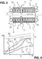
- Fig. 3 shows a tubular thermoelectric module 1 with a first wall 2 and a second wall 3.
- the second wall 3 forms here an inner channel of the tubular thermoelectric module 1, which is designed here as a cold side 13 and thus, for example, for cooling water can flow.
- the outer peripheral surface of the thermoelectric module 1, which is formed by the second wall 2 is designed as a hot side 17 and z. B. be flowed by a hot exhaust gas. Starting from the hot side 17, a heat flow in the direction of the main heat flow direction 8 toward the cold side 13 is generated. This results in an expansion of the thermoelectric materials 5 in a direction parallel to the main heat flow direction 8 and corresponding to a second compressive stress 11.
- This second compressive stress 11 is caused by the different expansion of the individual components 19 of the thermoelectric module 1, for example the thermoelectric materials 5 and This second compressive stress 11 is now compensated by applying a compressive force 15, which causes a first compressive stress 7 between the thermoelectric materials 5 insofar that an expansion due to transverse contraction and / or creep / plastic deformation of the thermoelectric materials 5 in a direction 16 transverse to the main heat flow direction 8 does not take place.
- thermoelectric materials 5 in which filling materials 6 are arranged and by which the adjacently arranged thermoelectric elements 4 are spaced from each other.
- insulation 23 and connections 24 are respectively provided on the first wall 2 and on the second wall 3.
- Fig. 4 shows illustratively the course of compressive stresses in an operating range of the thermoelectric module 1.
- the temperature 25 is plotted, on the right vertical axis of the Amount of compressive stress 27.
- the horizontal axis describes the operating time 26. It can be seen that as the operating time 26 progresses, the temperature 25 on the hot side 17 increases or takes a specific course. Accordingly, due to the main heat flow, the temperature 25 at the cold side 13 of the thermoelectric module 1 also increases.
- a temperature potential 10 is formed in an operating region 9 shown on the horizontal axis.
- thermoelectric materials 5 in a direction parallel to the main heat flux 8 is smaller than a first compressive stress 7 applied to the thermoelectric materials 5 in a direction 16 transverse to the main heat flux 8.
- the inclination of the elements 4 for expansion due to transverse contraction (when exceeding the first limit voltage 34) or due to plastic deformation (when exceeding the second limit voltage 35) in a direction transverse to the main heat flow direction 8 is reduced by the application of the elements 4 with the second compressive stress 11 or prevented.
- This "clamping" of the thermoelectric elements 4 prevents, in particular, that the first limit voltage 34 and / or the second limit voltage 35 of the thermoelectric material are exceeded.
- thermoelectric generator 18 with two thermoelectric modules 1. These each have a hot side 17 and a cold side 13, between which forms a heat flow in a main heat flow direction 8.
- the thermoelectric modules 1 have at their respective cold side 13 and at its, the cold side 13 forming the second wall 3, a bracing device 14. This bracing device 14 is supported on the thermoelectric generator 18 or on its housing and acts equally on the respective cold side 13 of the two thermoelectric modules. 1
- Fig. 6 shows a motor vehicle 20 with an internal combustion engine 29, a cooling system 28 and an exhaust system 22.
- a cold medium 21 flows, starting from the cooling 28, thermoelectric modules 1, which are arranged within a thermoelectric generator 18.
- a hot medium 21 flows through the thermoelectric modules 1, starting from the internal combustion engine or from the exhaust system 22.
Landscapes
- Cooling Or The Like Of Semiconductors Or Solid State Devices (AREA)
- Air-Conditioning For Vehicles (AREA)
- Measuring Temperature Or Quantity Of Heat (AREA)
- Electromechanical Clocks (AREA)
Applications Claiming Priority (2)
| Application Number | Priority Date | Filing Date | Title |
|---|---|---|---|
| DE201210104927 DE102012104927A1 (de) | 2012-06-06 | 2012-06-06 | Thermoelektrisches Modul und Verfahren zum Betrieb |
| PCT/EP2013/060765 WO2013182441A2 (de) | 2012-06-06 | 2013-05-24 | Thermoelektrisches modul und verfahren zum betrieb |
Publications (2)
| Publication Number | Publication Date |
|---|---|
| EP2859598A2 EP2859598A2 (de) | 2015-04-15 |
| EP2859598B1 true EP2859598B1 (de) | 2018-03-21 |
Family
ID=48570100
Family Applications (1)
| Application Number | Title | Priority Date | Filing Date |
|---|---|---|---|
| EP13726479.2A Active EP2859598B1 (de) | 2012-06-06 | 2013-05-24 | Thermoelektrisches modul und verfahren zum betrieb |
Country Status (9)
| Country | Link |
|---|---|
| US (1) | US20150114440A1 (ja) |
| EP (1) | EP2859598B1 (ja) |
| JP (1) | JP6173445B2 (ja) |
| KR (1) | KR101657391B1 (ja) |
| CN (1) | CN104335373B (ja) |
| DE (1) | DE102012104927A1 (ja) |
| IN (1) | IN2014DN09760A (ja) |
| RU (1) | RU2630540C2 (ja) |
| WO (1) | WO2013182441A2 (ja) |
Families Citing this family (1)
| Publication number | Priority date | Publication date | Assignee | Title |
|---|---|---|---|---|
| GB2521353A (en) * | 2013-12-17 | 2015-06-24 | Ibm | Thermoelectric device |
Family Cites Families (18)
| Publication number | Priority date | Publication date | Assignee | Title |
|---|---|---|---|---|
| US3090206A (en) * | 1960-06-23 | 1963-05-21 | Frank W Anders | Thermoelectric devices and circuits therefor |
| DE1539330A1 (de) * | 1966-12-06 | 1969-11-06 | Siemens Ag | Thermoelektrische Anordnung |
| JPH0768961B2 (ja) * | 1987-10-20 | 1995-07-26 | ノーヴァ‐ウエルケ・アクチェンゲゼルシャフト | 油圧式増幅器を備えた直線駆動装置 |
| JPH08288557A (ja) * | 1995-02-17 | 1996-11-01 | Matsushita Electric Works Ltd | 熱電気変換装置 |
| JPH08335722A (ja) * | 1995-06-08 | 1996-12-17 | Ngk Insulators Ltd | 熱電変換モジュール |
| JPH0992890A (ja) * | 1995-09-25 | 1997-04-04 | Matsushita Electric Works Ltd | 熱電気変換装置 |
| US7273981B2 (en) * | 2001-02-09 | 2007-09-25 | Bsst, Llc. | Thermoelectric power generation systems |
| US6410971B1 (en) | 2001-07-12 | 2002-06-25 | Ferrotec (Usa) Corporation | Thermoelectric module with thin film substrates |
| JP2004063656A (ja) * | 2002-07-26 | 2004-02-26 | Toshiba Corp | 熱電変換装置 |
| JP4488778B2 (ja) * | 2003-07-25 | 2010-06-23 | 株式会社東芝 | 熱電変換装置 |
| JP2005127162A (ja) * | 2003-10-21 | 2005-05-19 | Toyota Motor Corp | 排熱回収装置 |
| JP4266228B2 (ja) * | 2006-03-24 | 2009-05-20 | 株式会社東芝 | 熱電変換モジュールおよびその製造方法 |
| US20070272292A1 (en) * | 2006-05-24 | 2007-11-29 | Jerrei Lin | Thermal-recycling system for a motor vehicle |
| JP2008270618A (ja) * | 2007-04-23 | 2008-11-06 | Toyota Motor Corp | 熱電発電モジュール |
| JP2008288535A (ja) * | 2007-05-21 | 2008-11-27 | Toyota Motor Corp | 熱電発電モジュール |
| WO2009142240A1 (ja) * | 2008-05-23 | 2009-11-26 | 株式会社村田製作所 | 熱電変換モジュールおよび熱電変換モジュールの製造方法 |
| JP5295824B2 (ja) * | 2009-03-09 | 2013-09-18 | 住友化学株式会社 | 熱電変換モジュール |
| DE102010044803A1 (de) * | 2010-09-09 | 2012-03-15 | Emitec Gesellschaft Für Emissionstechnologie Mbh | Thermoelektrisches Modul für einen thermoelektrischen Generator eines Fahrzeugs mit einem Dichtelement |
-
2012
- 2012-06-06 DE DE201210104927 patent/DE102012104927A1/de not_active Withdrawn
-
2013
- 2013-05-24 EP EP13726479.2A patent/EP2859598B1/de active Active
- 2013-05-24 KR KR1020147035660A patent/KR101657391B1/ko active IP Right Grant
- 2013-05-24 RU RU2014154138A patent/RU2630540C2/ru active
- 2013-05-24 JP JP2015515466A patent/JP6173445B2/ja active Active
- 2013-05-24 CN CN201380029788.2A patent/CN104335373B/zh active Active
- 2013-05-24 WO PCT/EP2013/060765 patent/WO2013182441A2/de active Application Filing
-
2014
- 2014-11-18 IN IN9760DEN2014 patent/IN2014DN09760A/en unknown
- 2014-12-08 US US14/562,949 patent/US20150114440A1/en not_active Abandoned
Also Published As
| Publication number | Publication date |
|---|---|
| JP6173445B2 (ja) | 2017-08-02 |
| JP2015524171A (ja) | 2015-08-20 |
| KR101657391B1 (ko) | 2016-09-19 |
| CN104335373B (zh) | 2018-04-03 |
| RU2630540C2 (ru) | 2017-09-11 |
| DE102012104927A1 (de) | 2013-12-12 |
| WO2013182441A2 (de) | 2013-12-12 |
| EP2859598A2 (de) | 2015-04-15 |
| US20150114440A1 (en) | 2015-04-30 |
| WO2013182441A3 (de) | 2014-09-12 |
| KR20150013326A (ko) | 2015-02-04 |
| CN104335373A (zh) | 2015-02-04 |
| IN2014DN09760A (ja) | 2015-07-31 |
| RU2014154138A (ru) | 2016-08-10 |
Similar Documents
| Publication | Publication Date | Title |
|---|---|---|
| DE112007002615B4 (de) | Thermoelektrische Vorrichtung und thermoelektrisches Modul | |
| EP2668676B1 (de) | Thermoelektrisches modul mit einer wärmeleitschicht | |
| DE102009013692A1 (de) | Thermoelektrische Vorrichtung | |
| EP2609636B1 (de) | Halbleiterelement und isolationsmaterial in ringform für ein thermoelektrisches modul | |
| EP2454456A1 (de) | Thermoelektrische vorrichtung mit rohrbündeln | |
| DE202010018101U1 (de) | Thermoelektrische Generatorvorrichtung | |
| WO2009077468A2 (de) | Thermoelektrisches modul und thermoelektrischer generator | |
| EP2865023A1 (de) | Thermoelektrisches modul, wärmetauscher, abgasanlage und brennkraftmaschine | |
| EP2664014B1 (de) | Thermoelektrisches modul mit mitteln zur kompensation einer wärmeausdehnung | |
| DE102007063196A1 (de) | Thermoelektrischer Generator und Verfahren zur Herstellung eines thermoelektrischen Generators | |
| DE102013112911A1 (de) | Thermoelektrische Generatorvorrichtung und Verfahren zur Herstellung einer thermoelektrischen Generatorvorrichtung | |
| DE112013004906T5 (de) | Thermoelektrische Anordnung unter Verwendung einer Kartuschenhalterung | |
| DE102011005206A1 (de) | Thermoelektrischer Generator | |
| DE102014219853A1 (de) | Thermoelektrischer Generator | |
| EP2805361B1 (de) | Halbleiterelement zum einsatz in einem thermoelektrischen modul | |
| EP2859598B1 (de) | Thermoelektrisches modul und verfahren zum betrieb | |
| EP2630671B1 (de) | Halbleiterelemente bestehend aus thermoelektrischem material zum einsatz in einem thermoelektrischen modul | |
| DE202016106782U1 (de) | Wärmeübertragungsvorrichtung | |
| DE102016206507A1 (de) | Thermoelektrisches Modul | |
| DE202010007872U1 (de) | Thermoelektrischer Generator | |
| WO2011083116A2 (de) | Vorrichtung zur erzeugung elektrischer energie aus einem wärmeleitenden material | |
| DE102016208070A1 (de) | Thermoelektrisches Modul | |
| DE102016206506A1 (de) | Thermoelektrisches Modul | |
| DE202007005127U1 (de) | Halbleiterblockelement und daraus gebildetes Energieerzeugungssystem | |
| DE102020104425A1 (de) | Thermoelektrische Generatorvorrichtung, Fahrzeug und Verfahren zur Herstellung einer thermoelektrischen Generatorvorrichtung |
Legal Events
| Date | Code | Title | Description |
|---|---|---|---|
| PUAI | Public reference made under article 153(3) epc to a published international application that has entered the european phase |
Free format text: ORIGINAL CODE: 0009012 |
|
| 17P | Request for examination filed |
Effective date: 20141210 |
|
| AK | Designated contracting states |
Kind code of ref document: A2 Designated state(s): AL AT BE BG CH CY CZ DE DK EE ES FI FR GB GR HR HU IE IS IT LI LT LU LV MC MK MT NL NO PL PT RO RS SE SI SK SM TR |
|
| AX | Request for extension of the european patent |
Extension state: BA ME |
|
| DAX | Request for extension of the european patent (deleted) | ||
| RAP1 | Party data changed (applicant data changed or rights of an application transferred) |
Owner name: CONTINENTAL AUTOMOTIVE GMBH |
|
| GRAP | Despatch of communication of intention to grant a patent |
Free format text: ORIGINAL CODE: EPIDOSNIGR1 |
|
| INTG | Intention to grant announced |
Effective date: 20171110 |
|
| GRAS | Grant fee paid |
Free format text: ORIGINAL CODE: EPIDOSNIGR3 |
|
| GRAA | (expected) grant |
Free format text: ORIGINAL CODE: 0009210 |
|
| AK | Designated contracting states |
Kind code of ref document: B1 Designated state(s): AL AT BE BG CH CY CZ DE DK EE ES FI FR GB GR HR HU IE IS IT LI LT LU LV MC MK MT NL NO PL PT RO RS SE SI SK SM TR |
|
| REG | Reference to a national code |
Ref country code: GB Ref legal event code: FG4D Free format text: NOT ENGLISH |
|
| REG | Reference to a national code |
Ref country code: CH Ref legal event code: EP |
|
| REG | Reference to a national code |
Ref country code: AT Ref legal event code: REF Ref document number: 981969 Country of ref document: AT Kind code of ref document: T Effective date: 20180415 |
|
| REG | Reference to a national code |
Ref country code: IE Ref legal event code: FG4D Free format text: LANGUAGE OF EP DOCUMENT: GERMAN |
|
| REG | Reference to a national code |
Ref country code: DE Ref legal event code: R096 Ref document number: 502013009715 Country of ref document: DE |
|
| REG | Reference to a national code |
Ref country code: FR Ref legal event code: PLFP Year of fee payment: 6 |
|
| REG | Reference to a national code |
Ref country code: NL Ref legal event code: MP Effective date: 20180321 |
|
| PG25 | Lapsed in a contracting state [announced via postgrant information from national office to epo] |
Ref country code: NO Free format text: LAPSE BECAUSE OF FAILURE TO SUBMIT A TRANSLATION OF THE DESCRIPTION OR TO PAY THE FEE WITHIN THE PRESCRIBED TIME-LIMIT Effective date: 20180621 Ref country code: LT Free format text: LAPSE BECAUSE OF FAILURE TO SUBMIT A TRANSLATION OF THE DESCRIPTION OR TO PAY THE FEE WITHIN THE PRESCRIBED TIME-LIMIT Effective date: 20180321 Ref country code: FI Free format text: LAPSE BECAUSE OF FAILURE TO SUBMIT A TRANSLATION OF THE DESCRIPTION OR TO PAY THE FEE WITHIN THE PRESCRIBED TIME-LIMIT Effective date: 20180321 Ref country code: HR Free format text: LAPSE BECAUSE OF FAILURE TO SUBMIT A TRANSLATION OF THE DESCRIPTION OR TO PAY THE FEE WITHIN THE PRESCRIBED TIME-LIMIT Effective date: 20180321 Ref country code: CY Free format text: LAPSE BECAUSE OF FAILURE TO SUBMIT A TRANSLATION OF THE DESCRIPTION OR TO PAY THE FEE WITHIN THE PRESCRIBED TIME-LIMIT Effective date: 20180321 |
|
| REG | Reference to a national code |
Ref country code: LT Ref legal event code: MG4D |
|
| PG25 | Lapsed in a contracting state [announced via postgrant information from national office to epo] |
Ref country code: BG Free format text: LAPSE BECAUSE OF FAILURE TO SUBMIT A TRANSLATION OF THE DESCRIPTION OR TO PAY THE FEE WITHIN THE PRESCRIBED TIME-LIMIT Effective date: 20180621 Ref country code: RS Free format text: LAPSE BECAUSE OF FAILURE TO SUBMIT A TRANSLATION OF THE DESCRIPTION OR TO PAY THE FEE WITHIN THE PRESCRIBED TIME-LIMIT Effective date: 20180321 Ref country code: LV Free format text: LAPSE BECAUSE OF FAILURE TO SUBMIT A TRANSLATION OF THE DESCRIPTION OR TO PAY THE FEE WITHIN THE PRESCRIBED TIME-LIMIT Effective date: 20180321 Ref country code: SE Free format text: LAPSE BECAUSE OF FAILURE TO SUBMIT A TRANSLATION OF THE DESCRIPTION OR TO PAY THE FEE WITHIN THE PRESCRIBED TIME-LIMIT Effective date: 20180321 Ref country code: GR Free format text: LAPSE BECAUSE OF FAILURE TO SUBMIT A TRANSLATION OF THE DESCRIPTION OR TO PAY THE FEE WITHIN THE PRESCRIBED TIME-LIMIT Effective date: 20180622 |
|
| PG25 | Lapsed in a contracting state [announced via postgrant information from national office to epo] |
Ref country code: MT Free format text: LAPSE BECAUSE OF FAILURE TO SUBMIT A TRANSLATION OF THE DESCRIPTION OR TO PAY THE FEE WITHIN THE PRESCRIBED TIME-LIMIT Effective date: 20180321 |
|
| PG25 | Lapsed in a contracting state [announced via postgrant information from national office to epo] |
Ref country code: NL Free format text: LAPSE BECAUSE OF FAILURE TO SUBMIT A TRANSLATION OF THE DESCRIPTION OR TO PAY THE FEE WITHIN THE PRESCRIBED TIME-LIMIT Effective date: 20180321 Ref country code: EE Free format text: LAPSE BECAUSE OF FAILURE TO SUBMIT A TRANSLATION OF THE DESCRIPTION OR TO PAY THE FEE WITHIN THE PRESCRIBED TIME-LIMIT Effective date: 20180321 Ref country code: PL Free format text: LAPSE BECAUSE OF FAILURE TO SUBMIT A TRANSLATION OF THE DESCRIPTION OR TO PAY THE FEE WITHIN THE PRESCRIBED TIME-LIMIT Effective date: 20180321 Ref country code: AL Free format text: LAPSE BECAUSE OF FAILURE TO SUBMIT A TRANSLATION OF THE DESCRIPTION OR TO PAY THE FEE WITHIN THE PRESCRIBED TIME-LIMIT Effective date: 20180321 Ref country code: IT Free format text: LAPSE BECAUSE OF FAILURE TO SUBMIT A TRANSLATION OF THE DESCRIPTION OR TO PAY THE FEE WITHIN THE PRESCRIBED TIME-LIMIT Effective date: 20180321 Ref country code: RO Free format text: LAPSE BECAUSE OF FAILURE TO SUBMIT A TRANSLATION OF THE DESCRIPTION OR TO PAY THE FEE WITHIN THE PRESCRIBED TIME-LIMIT Effective date: 20180321 Ref country code: ES Free format text: LAPSE BECAUSE OF FAILURE TO SUBMIT A TRANSLATION OF THE DESCRIPTION OR TO PAY THE FEE WITHIN THE PRESCRIBED TIME-LIMIT Effective date: 20180321 |
|
| PG25 | Lapsed in a contracting state [announced via postgrant information from national office to epo] |
Ref country code: CZ Free format text: LAPSE BECAUSE OF FAILURE TO SUBMIT A TRANSLATION OF THE DESCRIPTION OR TO PAY THE FEE WITHIN THE PRESCRIBED TIME-LIMIT Effective date: 20180321 Ref country code: SM Free format text: LAPSE BECAUSE OF FAILURE TO SUBMIT A TRANSLATION OF THE DESCRIPTION OR TO PAY THE FEE WITHIN THE PRESCRIBED TIME-LIMIT Effective date: 20180321 Ref country code: SK Free format text: LAPSE BECAUSE OF FAILURE TO SUBMIT A TRANSLATION OF THE DESCRIPTION OR TO PAY THE FEE WITHIN THE PRESCRIBED TIME-LIMIT Effective date: 20180321 |
|
| REG | Reference to a national code |
Ref country code: CH Ref legal event code: PL |
|
| PG25 | Lapsed in a contracting state [announced via postgrant information from national office to epo] |
Ref country code: PT Free format text: LAPSE BECAUSE OF FAILURE TO SUBMIT A TRANSLATION OF THE DESCRIPTION OR TO PAY THE FEE WITHIN THE PRESCRIBED TIME-LIMIT Effective date: 20180723 |
|
| REG | Reference to a national code |
Ref country code: DE Ref legal event code: R097 Ref document number: 502013009715 Country of ref document: DE |
|
| PLBE | No opposition filed within time limit |
Free format text: ORIGINAL CODE: 0009261 |
|
| STAA | Information on the status of an ep patent application or granted ep patent |
Free format text: STATUS: NO OPPOSITION FILED WITHIN TIME LIMIT |
|
| REG | Reference to a national code |
Ref country code: BE Ref legal event code: MM Effective date: 20180531 |
|
| PG25 | Lapsed in a contracting state [announced via postgrant information from national office to epo] |
Ref country code: MC Free format text: LAPSE BECAUSE OF FAILURE TO SUBMIT A TRANSLATION OF THE DESCRIPTION OR TO PAY THE FEE WITHIN THE PRESCRIBED TIME-LIMIT Effective date: 20180321 Ref country code: DK Free format text: LAPSE BECAUSE OF FAILURE TO SUBMIT A TRANSLATION OF THE DESCRIPTION OR TO PAY THE FEE WITHIN THE PRESCRIBED TIME-LIMIT Effective date: 20180321 |
|
| REG | Reference to a national code |
Ref country code: IE Ref legal event code: MM4A |
|
| 26N | No opposition filed |
Effective date: 20190102 |
|
| GBPC | Gb: european patent ceased through non-payment of renewal fee |
Effective date: 20180621 |
|
| PG25 | Lapsed in a contracting state [announced via postgrant information from national office to epo] |
Ref country code: CH Free format text: LAPSE BECAUSE OF NON-PAYMENT OF DUE FEES Effective date: 20180531 Ref country code: LI Free format text: LAPSE BECAUSE OF NON-PAYMENT OF DUE FEES Effective date: 20180531 |
|
| PG25 | Lapsed in a contracting state [announced via postgrant information from national office to epo] |
Ref country code: LU Free format text: LAPSE BECAUSE OF NON-PAYMENT OF DUE FEES Effective date: 20180524 |
|
| PG25 | Lapsed in a contracting state [announced via postgrant information from national office to epo] |
Ref country code: GB Free format text: LAPSE BECAUSE OF NON-PAYMENT OF DUE FEES Effective date: 20180621 Ref country code: IE Free format text: LAPSE BECAUSE OF NON-PAYMENT OF DUE FEES Effective date: 20180524 |
|
| PG25 | Lapsed in a contracting state [announced via postgrant information from national office to epo] |
Ref country code: SI Free format text: LAPSE BECAUSE OF FAILURE TO SUBMIT A TRANSLATION OF THE DESCRIPTION OR TO PAY THE FEE WITHIN THE PRESCRIBED TIME-LIMIT Effective date: 20180321 Ref country code: BE Free format text: LAPSE BECAUSE OF NON-PAYMENT OF DUE FEES Effective date: 20180531 |
|
| REG | Reference to a national code |
Ref country code: AT Ref legal event code: MM01 Ref document number: 981969 Country of ref document: AT Kind code of ref document: T Effective date: 20180524 |
|
| PG25 | Lapsed in a contracting state [announced via postgrant information from national office to epo] |
Ref country code: AT Free format text: LAPSE BECAUSE OF NON-PAYMENT OF DUE FEES Effective date: 20180524 |
|
| PG25 | Lapsed in a contracting state [announced via postgrant information from national office to epo] |
Ref country code: TR Free format text: LAPSE BECAUSE OF FAILURE TO SUBMIT A TRANSLATION OF THE DESCRIPTION OR TO PAY THE FEE WITHIN THE PRESCRIBED TIME-LIMIT Effective date: 20180321 |
|
| REG | Reference to a national code |
Ref country code: DE Ref legal event code: R081 Ref document number: 502013009715 Country of ref document: DE Owner name: EMITEC TECHNOLOGIES GMBH, DE Free format text: FORMER OWNER: CONTINENTAL AUTOMOTIVE GMBH, 30165 HANNOVER, DE Ref country code: DE Ref legal event code: R081 Ref document number: 502013009715 Country of ref document: DE Owner name: VITESCO TECHNOLOGIES GMBH, DE Free format text: FORMER OWNER: CONTINENTAL AUTOMOTIVE GMBH, 30165 HANNOVER, DE |
|
| PG25 | Lapsed in a contracting state [announced via postgrant information from national office to epo] |
Ref country code: HU Free format text: LAPSE BECAUSE OF FAILURE TO SUBMIT A TRANSLATION OF THE DESCRIPTION OR TO PAY THE FEE WITHIN THE PRESCRIBED TIME-LIMIT; INVALID AB INITIO Effective date: 20130524 Ref country code: MK Free format text: LAPSE BECAUSE OF NON-PAYMENT OF DUE FEES Effective date: 20180321 |
|
| PG25 | Lapsed in a contracting state [announced via postgrant information from national office to epo] |
Ref country code: IS Free format text: LAPSE BECAUSE OF FAILURE TO SUBMIT A TRANSLATION OF THE DESCRIPTION OR TO PAY THE FEE WITHIN THE PRESCRIBED TIME-LIMIT Effective date: 20180721 |
|
| REG | Reference to a national code |
Ref country code: DE Ref legal event code: R081 Ref document number: 502013009715 Country of ref document: DE Owner name: EMITEC TECHNOLOGIES GMBH, DE Free format text: FORMER OWNER: VITESCO TECHNOLOGIES GMBH, 30165 HANNOVER, DE Ref country code: DE Ref legal event code: R081 Ref document number: 502013009715 Country of ref document: DE Owner name: VITESCO TECHNOLOGIES GMBH, DE Free format text: FORMER OWNER: VITESCO TECHNOLOGIES GMBH, 30165 HANNOVER, DE |
|
| REG | Reference to a national code |
Ref country code: DE Ref legal event code: R084 Ref document number: 502013009715 Country of ref document: DE |
|
| REG | Reference to a national code |
Ref country code: DE Ref legal event code: R079 Ref document number: 502013009715 Country of ref document: DE Free format text: PREVIOUS MAIN CLASS: H01L0035300000 Ipc: H10N0010130000 |
|
| P01 | Opt-out of the competence of the unified patent court (upc) registered |
Effective date: 20230530 |
|
| REG | Reference to a national code |
Ref country code: DE Ref legal event code: R081 Ref document number: 502013009715 Country of ref document: DE Owner name: EMITEC TECHNOLOGIES GMBH, DE Free format text: FORMER OWNER: VITESCO TECHNOLOGIES GMBH, 93055 REGENSBURG, DE |
|
| PGFP | Annual fee paid to national office [announced via postgrant information from national office to epo] |
Ref country code: DE Payment date: 20240523 Year of fee payment: 12 |
|
| PGFP | Annual fee paid to national office [announced via postgrant information from national office to epo] |
Ref country code: FR Payment date: 20240522 Year of fee payment: 12 |