EP2859564B1 - Noyau à trois étages pour transformateur non linéaire - Google Patents
Noyau à trois étages pour transformateur non linéaire Download PDFInfo
- Publication number
- EP2859564B1 EP2859564B1 EP13729574.7A EP13729574A EP2859564B1 EP 2859564 B1 EP2859564 B1 EP 2859564B1 EP 13729574 A EP13729574 A EP 13729574A EP 2859564 B1 EP2859564 B1 EP 2859564B1
- Authority
- EP
- European Patent Office
- Prior art keywords
- section
- lamination layers
- core
- layer
- lamination
- Prior art date
- Legal status (The legal status is an assumption and is not a legal conclusion. Google has not performed a legal analysis and makes no representation as to the accuracy of the status listed.)
- Not-in-force
Links
Images


Classifications
-
- H—ELECTRICITY
- H01—ELECTRIC ELEMENTS
- H01F—MAGNETS; INDUCTANCES; TRANSFORMERS; SELECTION OF MATERIALS FOR THEIR MAGNETIC PROPERTIES
- H01F27/00—Details of transformers or inductances, in general
- H01F27/24—Magnetic cores
- H01F27/245—Magnetic cores made from sheets, e.g. grain-oriented
-
- H—ELECTRICITY
- H01—ELECTRIC ELEMENTS
- H01F—MAGNETS; INDUCTANCES; TRANSFORMERS; SELECTION OF MATERIALS FOR THEIR MAGNETIC PROPERTIES
- H01F27/00—Details of transformers or inductances, in general
- H01F27/24—Magnetic cores
- H01F27/26—Fastening parts of the core together; Fastening or mounting the core on casing or support
- H01F27/263—Fastening parts of the core together
-
- H—ELECTRICITY
- H01—ELECTRIC ELEMENTS
- H01F—MAGNETS; INDUCTANCES; TRANSFORMERS; SELECTION OF MATERIALS FOR THEIR MAGNETIC PROPERTIES
- H01F30/00—Fixed transformers not covered by group H01F19/00
- H01F30/06—Fixed transformers not covered by group H01F19/00 characterised by the structure
- H01F30/12—Two-phase, three-phase or polyphase transformers
-
- H—ELECTRICITY
- H01—ELECTRIC ELEMENTS
- H01F—MAGNETS; INDUCTANCES; TRANSFORMERS; SELECTION OF MATERIALS FOR THEIR MAGNETIC PROPERTIES
- H01F38/00—Adaptations of transformers or inductances for specific applications or functions
- H01F38/02—Adaptations of transformers or inductances for specific applications or functions for non-linear operation
-
- Y—GENERAL TAGGING OF NEW TECHNOLOGICAL DEVELOPMENTS; GENERAL TAGGING OF CROSS-SECTIONAL TECHNOLOGIES SPANNING OVER SEVERAL SECTIONS OF THE IPC; TECHNICAL SUBJECTS COVERED BY FORMER USPC CROSS-REFERENCE ART COLLECTIONS [XRACs] AND DIGESTS
- Y10—TECHNICAL SUBJECTS COVERED BY FORMER USPC
- Y10T—TECHNICAL SUBJECTS COVERED BY FORMER US CLASSIFICATION
- Y10T29/00—Metal working
- Y10T29/49—Method of mechanical manufacture
- Y10T29/49002—Electrical device making
- Y10T29/4902—Electromagnet, transformer or inductor
- Y10T29/49071—Electromagnet, transformer or inductor by winding or coiling
Definitions
- the present application is directed to a transformer having a non-linear core and a method of manufacturing the non-linear core.
- Transformers having non-linear, or delta-shaped cores are typically more labor-intensive to manufacture than in-line core transformers, i.e. transformers having core legs arranged in a linear fashion between two yokes.
- transformers having core legs arranged in a linear fashion between two yokes i.e. transformers having core legs arranged in a linear fashion between two yokes.
- the resulting efficiency of non-linear transformers often outweighs the cost of producing them.
- a three-phase transformer according to the preamble of claim 1 is disclosed in document US 6 683 524 B1 . Further three-phase transformers according to the prior art are disclosed in documents WO 00/25327 A1 , CN 102 306 542 A , US 6 809 620 B2 .
- a three-phase non-linear transformer according to present claim 1 and a method of manufacturing a three-phase non-linear transformer core according to present claim 10.
- Preferred features are specified in dependent claims 2-9 and 11-15.
- a non-linear transformer 100 core 70 is shown in Fig. 1A .
- the core 70 for the non-linear transformer 100 is formed of a material such as amorphous metal or grain-oriented silicon steel.
- the transformer 100 exhibits lower hysteresis and eddy current energy losses.
- a transformer core 70 utilizing amorphous metal is difficult to produce.
- the thickness of amorphous metal used in forming the core 70 is about 0.025 mm thick whereas conventional grain-oriented silicon steel utilized in forming the core 70 is about 0.27 mm thick.
- the core 70 is formed from at least three core frames 22.
- Each of the at least three core frames 22 has two leg portions 28 and two yoke portions 26 connected together by shoulders 24 to form a substantially rectangular shape having rounded edges.
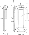
- Each leg portion 28 of the at least three core frames 22 abuts a leg portion 28 of another core frame 22 to form a core leg 80 as shown in Fig. 1D .
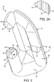
- Each of the at least three core legs 80, formed by two semi-circular leg portions 28, has a substantially circular cross section, as best shown in Fig.2 and the inset of Fig. 2A .
- the leg portions 28 of the at least three core legs 80 are secured together using a dielectric tape, band, or wrap.
- An assembled core 70 has a triangular shape when viewed from above as depicted in Fig. 1B .
- each core frame 22 of the core 70 is formed of three steps, ie. first, second, and third sections of laminations 10, 20, 30 comprising the first, second, and third steps, respectively.
- the first, second, and third sections of laminations 10, 20, 30 are embodied as strips, sheets, foils or wires of grain-oriented silicon steel or amorphous metal.
- the first, second and third sections of laminations 10, 20, 30 are comprised of continuous strips or sheets of metal.
- a core 70 comprised of grain-oriented silicon steel may be formed from continuous strips, sheets, foils or wires whereas a similar core 70 using amorphous metal is formed from continuous strips or sheets of metal. It should be understood that the number of layers of laminations in a core utilizing amorphous material or conventional grain-oriented silicon steel may vary widely depending upon the material used, the application, and the desired transformer output rating.
- first, second and third sections of laminations 10, 20, 30 have several wound layers that after winding have different cross-sectional areas, respectively.
- the first section of laminations 10 forms the interior portion of each core frame 22 and has a trapezoidal shape as depicted in Figs. 1B and 1C .
- the second section of laminations 20 forms the center portion of each core frame 22 and has a generally rhomboid or diamond-shaped cross section as is depicted in Fig. 2 .
- the third section of laminations 30 forms the outer portion of each core frame 22 and has a trapezoidal cross section and has a larger cross-sectional area than the first section of laminations 10. Overall, the second section of laminations 20 has the largest cross-sectional area.
- the first and third sections of laminations 10, 30 are formed using a standard cross-slitting machine that is well known in the art.
- the second section of laminations 20 utilizes a sheet of metal that does not require cross-slitting and may be of a standard size, such as 150 mm wide.
- the first and third sections of laminations 10, 30 may also be formed from a metal sheet or strip that is 150 mm wide before it is cross-slit.
- the first section of laminations 10 is formed from a generally rectangular sheet or strip of metal.
- the rectangular sheet is cross-slit using a diagonal cut across the length of the metal sheet or strip, forming two equal parts each having a generally triangular shape.
- a corner portion may be severed from the rectangular metal sheet or strip and discarded as scrap, leaving a single part.
- the winding of the first section of laminations 10 begins with the narrowest portion of the metal sheet whether the metal sheet or strip has a generally triangular shape or has a generally rectangular shape with a missing corner portion.
- the narrowest portion of the metal sheet is the portion that forms the smallest angle in relation to the right angle of a generally triangular shape or the portion having the severed corner in a generally rectangular metal sheet.
- the third section of laminations 30 is formed from a rectangular sheet of metal that is longer than the rectangular sheet used to form the first section of laminations 10.
- the rectangular metal sheet is cut diagonally across the length of the sheet to form two parts of equal size.
- Each of the two sections is used in a different core frame 22.
- the winding of the third section of laminations 30 begins with the widest portion of the metal sheet.
- the widest portion of the metal sheet is the opposite of side of the rectangular metal sheet from that which is chosen to begin the winding of the first section of laminations 10.
- a first part cut from the rectangular sheet of laminations is used the first section of laminations 10 and the second part is used in the third section of laminations 30.
- the cross-slit material is not used in the second section of laminations because the second section of laminations has a uniform width. Therefore, the cross-slitting machine is not utilized in the formation of the sheet or strip of metal used to produce the second section of laminations 20.
- the cross-sectional shape of the layers of laminations of the first, second, and third sections of laminations 10, 20, 30 that form a core frame 22 approximates the shape of a semi-circle as depicted in Fig. 2A .
- the core leg 80 has a substantially circular cross-sectional area.
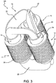
- the substantially circular cross-section of the core legs 80 provides an increased fill factor when used with circular primary and secondary coil windings 32, 34 as depicted in Fig. 3 .
- the fill factor of a transformer core 70 using first, second, and third sections of laminations 10, 20, 30 having different cross-sectional areas and angles of offset as described below may fill about 89 percent of the area inside a generally annular coil assembly 12 made up of primary and secondary coil windings 32, 34.
- the coil assemblies 12 are mounted to each of the at least three core legs, respectively.
- the coil assemblies 12 are formed of a secondary coil winding 34 mounted to each of the at least three core legs, respectively and a primary winding 32 disposed around the secondary winding 34.
- the transformer 100 is a so-called “step-down" transformer 100 which steps down the voltage and current values at the output of the transformer 100.
- the transformer 100 may be embodied as a "step-up" transformer 100 wherein the primary winding is a low voltage winding and the secondary winding 34 is a high voltage winding. It should be understood that in certain configurations the primary winding 32 may be wound around or otherwise mounted to each of the at least three core legs, respectively, and the secondary coil 34 winding may further be disposed around the primary coil winding 32.
- the first section 10 of laminations is wound directly on a generally rectangular mold having rounded edges.
- the first layer of the first section of laminations 10 of strip, sheet, foil or wire covers the outside end surfaces of the rectangular mold.
- the mold occupies the space of the core window 60 of the core frame 22, essentially creating the core window 60 during the core winding process.
- Successive layers of laminations form the various cross-sectional areas of the first, second and third sections of laminations 10, 20, 30, respectively.
- the first section of laminations 10 is wound upon the mold, the second section of laminations 20 is wound upon the first section of laminations 10, and the third section of laminations 30 is wound upon the second section of laminations 20.
- one or more layers of the second section of laminations may come in contact with the mold.
- the first section of laminations 10 is wound successively so that all adjacent laminations and/or at least the first layer of the first, second, and third sections of laminations 10, 20, 30 are offset by a predetermined angle from all surrounding laminations and/or the first layers 15, 25, 35 of the surrounding sections 10, 20, 30.
- the result is a trapezoidal cross section of the first section of laminations 10 as shown in the inset of Fig. 2a .
- Each of the first, second and third sections of laminations 10, 20, 30 begin as a pre-cut roll of lamination sheeting or strip that is placed onto a de-coiling device which may be manual or automatic in operation.
- the first section of laminations 10 is fed into a lamination shifting machine with the narrowest end portion of the sheet or strip fed first.
- the second section of laminations is a constant width so may be fed beginning with either end of the sheet or strip.
- the third section of laminations 30 is fed into the laminations shifting machine starting with the widest end portion of the sheet or strip.
- the lamination shifting machine which is used to control the offset angle of adjacent laminations.
- the lamination shifting machine is a form of linear automation that is known in the art of forming transformer cores 70.
- the lamination shifting machine has a table upon which are mounted a set of rollers and a clamping assembly. The lamination sheet or strip is first fed into the set of rollers and then the clamping assembly grasps and shifts the laminations to predetermined positions along a horizontal axis of the table of the lamination shifting machine.
- the lamination strip or sheet after being positioned at the proper angle of offset for each layer using the lamination shifting machine, is then fed into a core winding machine having a generally rectangular mold with rounded edges.
- a layer of the first, second or third groups of laminations 10, 20, 30 is created with each layer being offset at a predetermined angle from adjacent layers using the lamination shifting machine.
- a full rotation of the coil winding machine is the rotation of the mold from a single point, for example a point on the corner of the mold until the mold rotates forward or backward to that same single point on the corner of the mold.
- the lamination strips or sheets are wound successively, one layer upon another as the mold of the coil winding machine rotates end over end, with each layer of the lamination strip or sheet at a different offset angle from the previous layer.
- the result is a first section of laminations 10 having a trapezoidal cross section, the second section of laminations 20 having a rhombic cross section, and the third section of laminations 30 having a trapezoidal cross section as depicted in Fig. 1c .
- a cross-sectional view of a core frame 22 arranged on a Cartesian grid is shown.
- the direction 55 of the width of the first, second, and third sections of laminations 10, 20, 30 is denoted by an arrow having two ends, and corresponds to the y-axis of the grid.
- the core frame 22 is shown superimposed on the Cartesian grid to depict the manner in which the cross-section of the core frame 22 fills a semi-circle wherein the boundaries of the semi-circle are denoted by points representing the first layers of the first, second and third sections of laminations 15, 25, 35 and a point representing the last layer of the third section of laminations 45.
- the offset angle of the first layer of laminations in each of the first, second, and third sections of laminations 15, 25, 35 is about 10 degrees, about 30 degrees, and about 90 degrees, respectively, from the horizontal axis or x-axis of the grid as depicted in Fig. 4 . It follows that the first layer of the first group of laminations 15 is about ten degrees from the horizontal axis, the first layer of the second group of laminations 25 is about 20 degrees from the first layer of the first group of laminations 15, the first layer of the third group of laminations 35 is about 60 degrees from the first layer of the second group of laminations 25, and the last layer of the third group of laminations 45 is about 140 degrees from the horizontal axis. The last layer is of the third group of laminations 45 is also about 130 degrees from a first layer of the first group of laminations 15.
- each layer of each of the first, second, and third sections of laminations may be offset from each successive or adjacent layer by one or more pre-determined angles of offset with the goal of substantially filling a semi-circular or circular cross-sectional shape.
Landscapes
- Engineering & Computer Science (AREA)
- Power Engineering (AREA)
- Physics & Mathematics (AREA)
- Nonlinear Science (AREA)
- Manufacturing Cores, Coils, And Magnets (AREA)
- Coils Of Transformers For General Uses (AREA)
Claims (15)
- Transformateur non linéaire triphasé (100), comprenant :un noyau ferromagnétique (70) formé d'au moins trois cadres de noyau (22), chacun ayant une première (10), une deuxième (20) et une troisième (30) sections de couches de stratification successives, lesdits au moins trois cadres de noyau (22) étant agencés en configuration non linéaire, chacun desdits au moins trois cadres de noyau (22) comprenant une section de branche (28) et une section de culasse (26), chacune desdites sections de branche (28) se combinant à une section de branche (28) d'un autre cadre de noyau pour former au moins trois branches de noyau (80) ayant des sections transversales sensiblement circulaires, respectivement ; etdes ensembles de bobinage (12) montées sur chacune des au moins trois branches de noyau (80), lesdits ensembles de bobines comprenant :un enroulement secondaire (34) enroulé autour de chacune des au moins trois branches de noyau (80), respectivement ;dans lequel chacune desdites première (10), deuxième (20) et troisième (30) sections de couches de stratification est enroulée successivement pour former une section transversale de couches de stratification approximativement en forme d'un demi-cercle, dans lequel la première couche de chaque section de couches de stratification est positionnée selon un certain angle de décalage vis-à-vis de la première couche de sections adjacentes, dans lequel la première section (10) de couches de stratification a une forme trapézoïdale, la deuxième section (20) de couches de stratification a une forme rhombique et la troisième section (30) de couches de stratification a une forme trapézoïdale,caractérisé en ce que la première section (10) de couches de stratification comprend un premier côté externe et un premier côté interne sur les côtés opposés de la première section (10), le premier côté externe étant plus étroit que le premier côté interne, et la troisième section (30) de couches de stratification comprend un second côté interne et un second côté externe sur les côtés opposés de la troisième section (30), le second côté externe étant plus étroit que le second côté interne, le premier et le second côté interne étant adjacents aux côtés opposés de la deuxième section (20),et en ce que lesdits ensembles de bobinage (12) comprennent en outre :un enroulement primaire (32) disposé autour de chacun des enroulements secondaires (34).
- Transformateur non linéaire (100) selon la revendication 1, dans lequel les au moins trois branches de noyau (80) sont agencées en configuration triangulaire et, en outre, dans lequel une largeur en coupe transversale de la deuxième section (20) comprise entre la première section (10) et la deuxième section (30) est uniforme.
- Transformateur non linéaire (100) selon la revendication 1, dans lequel ladite troisième section (30) de couches de stratification a une section transversale plus grande que ladite première section (10) de couches de stratification.
- Transformateur non linéaire (100) selon la revendication 1, dans lequel lesdites première (10), deuxième (20) et troisième (30) sections de couches de stratification sont formées d'un métal amorphe.
- Transformateur non linéaire (100) selon la revendication 1, dans lequel lesdites première (10), deuxième (20) et troisième (30) sections de couches de stratification sont formées d'acier au silicium à grain orienté.
- Transformateur non linéaire (100) selon la revendication 1, dans lequel la première couche de ladite première section (10) de couches de stratification est décalée d'environ 10 degrés par rapport à une branche de noyau (80) positionnée sur un axe horizontal.
- Transformateur non linéaire (100) selon la revendication 1, dans lequel la première couche de ladite première section (10) de couches de stratification est décalée d'environ 20 degrés par rapport à une première couche de la deuxième section (20) de couches de stratification par rapport à une branche de noyau (80) positionnée sur un axe horizontal.
- Transformateur non linéaire (100) selon la revendication 6, dans lequel une première couche de ladite deuxième section (20) de couches de stratification est décalée d'une première couche de la troisième section (30) de couches de stratification d'environ 60 degrés par rapport à ladite branche de noyau (80) positionnée sur ledit axe horizontal.
- Transformateur non linéaire (100) selon la revendication 7, dans lequel une dernière couche de ladite troisième section (30) de couches de stratification est décalée d'une première couche d'une première section (10) de couches de stratification d'environ 130 degrés par rapport à ladite branche de noyau (80) positionnée sur ledit axe horizontal.
- Procédé de fabrication d'un noyau de transformateur non linéaire (100) comprenant :a. une refente transversale d'une première section (10) de couches de stratification ;b. un enroulement de ladite première section (10) de couches de stratification en couches successives autour d'un moule de sorte que chaque couche de stratification de ladite première section de couches de stratification ait un angle de décalage vis-à-vis de couches de stratification adjacentes dans la première section (10) et une deuxième section (20) ;c. un enroulement d'une deuxième section (20) de couches de stratification sur ladite première section (10) de couches de stratification de sorte que chaque couche de stratification de ladite deuxième section de couches de stratification ait un angle de décalage vis-à-vis de couches de stratification adjacentes dans ladite première section (10) et une troisième section (30) ;d. une refente transversale de ladite troisième section (30) de couches de stratification ;e. un enroulement de ladite troisième section (30) de couches de stratification sur ladite deuxième section (20) de couches de stratification de sorte que chaque couche de stratification de ladite troisième section (30) de couches de stratification ait un angle de décalage vis-à-vis de couches de stratification adjacentes de ladite deuxième section (20),dans lequel ladite section transversale de ladite première section (10) de couches de stratification a une forme trapézoïdale, ladite section transversale de ladite deuxième section (20) de couches de stratification a une forme rhombique et ladite section transversale de ladite troisième section (30) de couches de stratification a une forme trapézoïdale de manière à former une section transversale de couches de stratification se rapprochant de la forme d'un demi-cercle,
dans lequel la première section (10) de couches de stratification comprend un premier côté externe et un premier côté interne sur les côtés opposés de la première section (10), le premier côté externe étant plus étroit que le premier côté interne, et la troisième section (30) de couches de stratification comprend un second côté interne et un second côté externe sur les côtés opposés de la troisième section (30), le second côté externe étant plus étroit que le second côté interne, le premier et le second côté interne étant adjacents aux côtés opposés de la deuxième section (20). - Procédé selon la revendication 10, dans lequel les au moins trois branches de noyau (80) sont agencées en configuration triangulaire et, en outre, dans lequel une largeur en coupe transversale de la deuxième section (20) entre la première section (10) et la deuxième section (30) est uniforme.
- Procédé selon la revendication 10, dans lequel la première couche de ladite première section (10) de couches de stratification est décalée d'environ 10 degrés par rapport à une branche de noyau (80) positionnée sur un axe horizontal.
- Procédé selon la revendication 10, dans lequel la première couche de ladite première section (10) de couches de stratification est décalée d'environ 20 degrés par rapport à une première couche d'une deuxième section (20) de couches de stratification par rapport à une branche de noyau (80) positionnée sur un axe horizontal.
- Procédé selon la revendication 10, dans lequel une première couche de ladite deuxième section (20) de couches de stratification est décalée d'une la première couche de la troisième section (30) de couches de stratification d'environ 60 degrés par rapport à ladite branche de noyau (80) positionnée sur ledit axe horizontal.
- Procédé selon la revendication 10, dans lequel une dernière couche de ladite troisième section (30) de couches de stratification est décalée d'une première couche d'une première section (10) de couches de stratification d'environ 130 degrés par rapport à ladite branche de noyau (80) positionnée sur ledit axe horizontal.
Applications Claiming Priority (2)
| Application Number | Priority Date | Filing Date | Title |
|---|---|---|---|
| US13/489,565 US8729998B2 (en) | 2012-06-06 | 2012-06-06 | Three-step core for a non-linear transformer |
| PCT/US2013/044434 WO2013184872A1 (fr) | 2012-06-06 | 2013-06-06 | Noyau à trois étages pour transformateur non linéaire |
Publications (2)
| Publication Number | Publication Date |
|---|---|
| EP2859564A1 EP2859564A1 (fr) | 2015-04-15 |
| EP2859564B1 true EP2859564B1 (fr) | 2017-03-01 |
Family
ID=48628954
Family Applications (1)
| Application Number | Title | Priority Date | Filing Date |
|---|---|---|---|
| EP13729574.7A Not-in-force EP2859564B1 (fr) | 2012-06-06 | 2013-06-06 | Noyau à trois étages pour transformateur non linéaire |
Country Status (8)
| Country | Link |
|---|---|
| US (1) | US8729998B2 (fr) |
| EP (1) | EP2859564B1 (fr) |
| KR (1) | KR20150016995A (fr) |
| CN (1) | CN104350556A (fr) |
| BR (1) | BR112014030381A2 (fr) |
| CA (1) | CA2874171A1 (fr) |
| IN (1) | IN2014KN02794A (fr) |
| WO (1) | WO2013184872A1 (fr) |
Families Citing this family (11)
| Publication number | Priority date | Publication date | Assignee | Title |
|---|---|---|---|---|
| US6939314B2 (en) | 2001-05-25 | 2005-09-06 | Revivant Corporation | CPR compression device and method |
| DE102014103526A1 (de) | 2014-03-14 | 2015-09-17 | Maschinenfabrik Reinhausen Gmbh | Laststufenschalter, Stufentransformator zur Spannungsregelung und Verfahren zur Durchführung einer Umschaltung im Stufentransformator |
| EP2863403B1 (fr) * | 2013-10-18 | 2016-03-30 | ABB Technology AG | Transformateur |
| CN204117812U (zh) * | 2014-07-25 | 2015-01-21 | 海鸿电气有限公司 | 一种敞开式立体卷铁心干式变压器的线圈结构 |
| USD771728S1 (en) * | 2014-08-18 | 2016-11-15 | Tokuden Co., Ltd. | Three-leg iron core |
| USD800061S1 (en) | 2014-08-26 | 2017-10-17 | Tokuden Co., Ltd. | Transformer |
| CN105990006A (zh) * | 2015-02-15 | 2016-10-05 | 上海置信电气非晶有限公司 | 一种三相变压器的插拔式立体折铁心 |
| CN106653312A (zh) * | 2017-02-22 | 2017-05-10 | 戴芬 | 一种三角立体卷铁心变压器铁心和线圈及两者的装配方法 |
| CN206774379U (zh) * | 2017-04-01 | 2017-12-19 | 海鸿电气有限公司 | 一种新型的立体卷铁心变压器高压引线结构 |
| CN107331495B (zh) * | 2017-07-14 | 2024-04-12 | 合肥天威众元电气有限公司 | 一种三框三柱立体叠片式变压器铁芯 |
| FR3112648B1 (fr) * | 2020-07-20 | 2023-04-14 | Safran Electrical & Power | Procédé de fabrication de boucles pour circuit magnétique |
Citations (3)
| Publication number | Priority date | Publication date | Assignee | Title |
|---|---|---|---|---|
| WO2000025327A1 (fr) * | 1998-10-26 | 2000-05-04 | A.T.T. Advanced Transformer Technologies (1998) Ltd. | Transformateur triphase |
| US6809620B2 (en) * | 2000-02-06 | 2004-10-26 | Hoeglund Lennart | Transformer core |
| CN102306542A (zh) * | 2011-05-27 | 2012-01-04 | 广东海鸿变压器有限公司 | 非包封立体卷铁心非晶合金干式变压器 |
Family Cites Families (6)
| Publication number | Priority date | Publication date | Assignee | Title |
|---|---|---|---|---|
| FR2225820A2 (en) * | 1973-04-13 | 1974-11-08 | Unelec | Polyphase transformer with increased space factor - has individual polygonal wound and cut magnetic circuits |
| SU557679A1 (ru) | 1974-12-16 | 1978-06-05 | Предприятие П/Я Р-6747 | Трехфазный пространственный магнитопровод |
| US5202664A (en) | 1992-01-28 | 1993-04-13 | Poulsen Peder Ulrik | Three phase transformer with frame shaped winding assemblies |
| US6683524B1 (en) | 1998-09-02 | 2004-01-27 | Hoeglund Lennart | Transformer core |
| CA2751556A1 (fr) | 2009-02-05 | 2010-08-12 | John Shirley Hurst | Transformateur a trajet de flux continu en metal amorphe et son procede de fabrication |
| CN102314997A (zh) * | 2011-05-27 | 2012-01-11 | 广东海鸿变压器有限公司 | 非晶合金立体卷铁心 |
-
2012
- 2012-06-06 US US13/489,565 patent/US8729998B2/en not_active Expired - Fee Related
-
2013
- 2013-06-06 IN IN2794KON2014 patent/IN2014KN02794A/en unknown
- 2013-06-06 BR BR112014030381A patent/BR112014030381A2/pt not_active IP Right Cessation
- 2013-06-06 CA CA2874171A patent/CA2874171A1/fr not_active Abandoned
- 2013-06-06 WO PCT/US2013/044434 patent/WO2013184872A1/fr active Application Filing
- 2013-06-06 KR KR1020157000094A patent/KR20150016995A/ko not_active Application Discontinuation
- 2013-06-06 EP EP13729574.7A patent/EP2859564B1/fr not_active Not-in-force
- 2013-06-06 CN CN201380029819.4A patent/CN104350556A/zh active Pending
Patent Citations (3)
| Publication number | Priority date | Publication date | Assignee | Title |
|---|---|---|---|---|
| WO2000025327A1 (fr) * | 1998-10-26 | 2000-05-04 | A.T.T. Advanced Transformer Technologies (1998) Ltd. | Transformateur triphase |
| US6809620B2 (en) * | 2000-02-06 | 2004-10-26 | Hoeglund Lennart | Transformer core |
| CN102306542A (zh) * | 2011-05-27 | 2012-01-04 | 广东海鸿变压器有限公司 | 非包封立体卷铁心非晶合金干式变压器 |
Also Published As
| Publication number | Publication date |
|---|---|
| BR112014030381A2 (pt) | 2017-06-27 |
| KR20150016995A (ko) | 2015-02-13 |
| US8729998B2 (en) | 2014-05-20 |
| CA2874171A1 (fr) | 2013-12-12 |
| CN104350556A (zh) | 2015-02-11 |
| WO2013184872A1 (fr) | 2013-12-12 |
| US20130328652A1 (en) | 2013-12-12 |
| EP2859564A1 (fr) | 2015-04-15 |
| IN2014KN02794A (fr) | 2015-05-08 |
Similar Documents
| Publication | Publication Date | Title |
|---|---|---|
| EP2859564B1 (fr) | Noyau à trois étages pour transformateur non linéaire | |
| US10937580B2 (en) | Amorphous alloy transformer iron core of three-dimensional triangle structure | |
| EP2780917B1 (fr) | Procédé de fabrication de noyau à enroulement pour des configurations de noyau fractionné | |
| US7877861B2 (en) | Method of making a transformer having a stacked core with a split leg | |
| KR101867947B1 (ko) | 비결정질 금속으로 만들어진 삼각형 변압기 코어의 제조 방법 | |
| CN203536171U (zh) | 三相立体断口式卷铁心 | |
| CN103026435B (zh) | 电抗器装置 | |
| US2588173A (en) | Method of making magnetic cores | |
| CN103247424B (zh) | 三相立体断口式卷铁心 | |
| JPH0154843B2 (fr) | ||
| CN208923924U (zh) | 盘式电机及定子铁芯 | |
| JP2011135091A (ja) | 磁芯およびコイル部品 | |
| EP3503139B1 (fr) | Procédé et produit semi-fini de fabrication au moins un paquet-section de un composant magnétique doux | |
| JP2016146441A (ja) | 変圧器およびその製造方法 | |
| US20030005570A1 (en) | Method of fabricating an electrical core sheet assembly of circular cross section | |
| US3321822A (en) | Wound core method | |
| JP2003007536A (ja) | 磁芯およびコイル部品 | |
| CN109067025A (zh) | 盘式电机、盘式电机的定子铁芯及其制造方法 | |
| US20160133367A1 (en) | Methods and systems for fabricating amorphous ribbon assembly components for stacked transformer cores | |
| JPS5837681B2 (ja) | 内鉄形変圧器 | |
| JPS58101412A (ja) | 巻鉄心型変圧器の製造方法 | |
| JPS59178714A (ja) | 積層鉄心の製造方法 | |
| JPH0538831U (ja) | ノイズ除去用コイル | |
| JPS58202513A (ja) | トランス及びその製造方法 | |
| JPS58101410A (ja) | 巻鉄心型変圧器の製造方法 |
Legal Events
| Date | Code | Title | Description |
|---|---|---|---|
| PUAI | Public reference made under article 153(3) epc to a published international application that has entered the european phase |
Free format text: ORIGINAL CODE: 0009012 |
|
| 17P | Request for examination filed |
Effective date: 20141125 |
|
| AK | Designated contracting states |
Kind code of ref document: A1 Designated state(s): AL AT BE BG CH CY CZ DE DK EE ES FI FR GB GR HR HU IE IS IT LI LT LU LV MC MK MT NL NO PL PT RO RS SE SI SK SM TR |
|
| AX | Request for extension of the european patent |
Extension state: BA ME |
|
| DAX | Request for extension of the european patent (deleted) | ||
| 17Q | First examination report despatched |
Effective date: 20160418 |
|
| GRAJ | Information related to disapproval of communication of intention to grant by the applicant or resumption of examination proceedings by the epo deleted |
Free format text: ORIGINAL CODE: EPIDOSDIGR1 |
|
| GRAP | Despatch of communication of intention to grant a patent |
Free format text: ORIGINAL CODE: EPIDOSNIGR1 |
|
| INTG | Intention to grant announced |
Effective date: 20161019 |
|
| RIN1 | Information on inventor provided before grant (corrected) |
Inventor name: HARTMANN, THOMAS, A. Inventor name: OUTTEN, SAMUEL, S. |
|
| GRAS | Grant fee paid |
Free format text: ORIGINAL CODE: EPIDOSNIGR3 |
|
| GRAA | (expected) grant |
Free format text: ORIGINAL CODE: 0009210 |
|
| AK | Designated contracting states |
Kind code of ref document: B1 Designated state(s): AL AT BE BG CH CY CZ DE DK EE ES FI FR GB GR HR HU IE IS IT LI LT LU LV MC MK MT NL NO PL PT RO RS SE SI SK SM TR |
|
| REG | Reference to a national code |
Ref country code: GB Ref legal event code: FG4D |
|
| REG | Reference to a national code |
Ref country code: CH Ref legal event code: EP Ref country code: AT Ref legal event code: REF Ref document number: 872197 Country of ref document: AT Kind code of ref document: T Effective date: 20170315 |
|
| REG | Reference to a national code |
Ref country code: IE Ref legal event code: FG4D |
|
| REG | Reference to a national code |
Ref country code: DE Ref legal event code: R096 Ref document number: 602013017981 Country of ref document: DE |
|
| REG | Reference to a national code |
Ref country code: DE Ref legal event code: R081 Ref document number: 602013017981 Country of ref document: DE Owner name: ABB SCHWEIZ AG, CH Free format text: FORMER OWNER: ABB TECHNOLOGY AG, ZUERICH, CH |
|
| REG | Reference to a national code |
Ref country code: NL Ref legal event code: MP Effective date: 20170301 |
|
| REG | Reference to a national code |
Ref country code: LT Ref legal event code: MG4D |
|
| REG | Reference to a national code |
Ref country code: AT Ref legal event code: MK05 Ref document number: 872197 Country of ref document: AT Kind code of ref document: T Effective date: 20170301 |
|
| PG25 | Lapsed in a contracting state [announced via postgrant information from national office to epo] |
Ref country code: FI Free format text: LAPSE BECAUSE OF FAILURE TO SUBMIT A TRANSLATION OF THE DESCRIPTION OR TO PAY THE FEE WITHIN THE PRESCRIBED TIME-LIMIT Effective date: 20170301 Ref country code: LT Free format text: LAPSE BECAUSE OF FAILURE TO SUBMIT A TRANSLATION OF THE DESCRIPTION OR TO PAY THE FEE WITHIN THE PRESCRIBED TIME-LIMIT Effective date: 20170301 Ref country code: NO Free format text: LAPSE BECAUSE OF FAILURE TO SUBMIT A TRANSLATION OF THE DESCRIPTION OR TO PAY THE FEE WITHIN THE PRESCRIBED TIME-LIMIT Effective date: 20170601 Ref country code: HR Free format text: LAPSE BECAUSE OF FAILURE TO SUBMIT A TRANSLATION OF THE DESCRIPTION OR TO PAY THE FEE WITHIN THE PRESCRIBED TIME-LIMIT Effective date: 20170301 Ref country code: GR Free format text: LAPSE BECAUSE OF FAILURE TO SUBMIT A TRANSLATION OF THE DESCRIPTION OR TO PAY THE FEE WITHIN THE PRESCRIBED TIME-LIMIT Effective date: 20170602 |
|
| RAP2 | Party data changed (patent owner data changed or rights of a patent transferred) |
Owner name: ABB SCHWEIZ AG |
|
| PG25 | Lapsed in a contracting state [announced via postgrant information from national office to epo] |
Ref country code: BG Free format text: LAPSE BECAUSE OF FAILURE TO SUBMIT A TRANSLATION OF THE DESCRIPTION OR TO PAY THE FEE WITHIN THE PRESCRIBED TIME-LIMIT Effective date: 20170601 Ref country code: SE Free format text: LAPSE BECAUSE OF FAILURE TO SUBMIT A TRANSLATION OF THE DESCRIPTION OR TO PAY THE FEE WITHIN THE PRESCRIBED TIME-LIMIT Effective date: 20170301 Ref country code: ES Free format text: LAPSE BECAUSE OF FAILURE TO SUBMIT A TRANSLATION OF THE DESCRIPTION OR TO PAY THE FEE WITHIN THE PRESCRIBED TIME-LIMIT Effective date: 20170301 Ref country code: AT Free format text: LAPSE BECAUSE OF FAILURE TO SUBMIT A TRANSLATION OF THE DESCRIPTION OR TO PAY THE FEE WITHIN THE PRESCRIBED TIME-LIMIT Effective date: 20170301 Ref country code: LV Free format text: LAPSE BECAUSE OF FAILURE TO SUBMIT A TRANSLATION OF THE DESCRIPTION OR TO PAY THE FEE WITHIN THE PRESCRIBED TIME-LIMIT Effective date: 20170301 Ref country code: RS Free format text: LAPSE BECAUSE OF FAILURE TO SUBMIT A TRANSLATION OF THE DESCRIPTION OR TO PAY THE FEE WITHIN THE PRESCRIBED TIME-LIMIT Effective date: 20170301 |
|
| PG25 | Lapsed in a contracting state [announced via postgrant information from national office to epo] |
Ref country code: NL Free format text: LAPSE BECAUSE OF FAILURE TO SUBMIT A TRANSLATION OF THE DESCRIPTION OR TO PAY THE FEE WITHIN THE PRESCRIBED TIME-LIMIT Effective date: 20170301 |
|
| PG25 | Lapsed in a contracting state [announced via postgrant information from national office to epo] |
Ref country code: RO Free format text: LAPSE BECAUSE OF FAILURE TO SUBMIT A TRANSLATION OF THE DESCRIPTION OR TO PAY THE FEE WITHIN THE PRESCRIBED TIME-LIMIT Effective date: 20170301 Ref country code: EE Free format text: LAPSE BECAUSE OF FAILURE TO SUBMIT A TRANSLATION OF THE DESCRIPTION OR TO PAY THE FEE WITHIN THE PRESCRIBED TIME-LIMIT Effective date: 20170301 Ref country code: SK Free format text: LAPSE BECAUSE OF FAILURE TO SUBMIT A TRANSLATION OF THE DESCRIPTION OR TO PAY THE FEE WITHIN THE PRESCRIBED TIME-LIMIT Effective date: 20170301 Ref country code: CZ Free format text: LAPSE BECAUSE OF FAILURE TO SUBMIT A TRANSLATION OF THE DESCRIPTION OR TO PAY THE FEE WITHIN THE PRESCRIBED TIME-LIMIT Effective date: 20170301 |
|
| PG25 | Lapsed in a contracting state [announced via postgrant information from national office to epo] |
Ref country code: IS Free format text: LAPSE BECAUSE OF FAILURE TO SUBMIT A TRANSLATION OF THE DESCRIPTION OR TO PAY THE FEE WITHIN THE PRESCRIBED TIME-LIMIT Effective date: 20170701 Ref country code: PT Free format text: LAPSE BECAUSE OF FAILURE TO SUBMIT A TRANSLATION OF THE DESCRIPTION OR TO PAY THE FEE WITHIN THE PRESCRIBED TIME-LIMIT Effective date: 20170703 Ref country code: PL Free format text: LAPSE BECAUSE OF FAILURE TO SUBMIT A TRANSLATION OF THE DESCRIPTION OR TO PAY THE FEE WITHIN THE PRESCRIBED TIME-LIMIT Effective date: 20170301 Ref country code: SM Free format text: LAPSE BECAUSE OF FAILURE TO SUBMIT A TRANSLATION OF THE DESCRIPTION OR TO PAY THE FEE WITHIN THE PRESCRIBED TIME-LIMIT Effective date: 20170301 |
|
| REG | Reference to a national code |
Ref country code: DE Ref legal event code: R097 Ref document number: 602013017981 Country of ref document: DE |
|
| REG | Reference to a national code |
Ref country code: DE Ref legal event code: R119 Ref document number: 602013017981 Country of ref document: DE |
|
| PLBE | No opposition filed within time limit |
Free format text: ORIGINAL CODE: 0009261 |
|
| STAA | Information on the status of an ep patent application or granted ep patent |
Free format text: STATUS: NO OPPOSITION FILED WITHIN TIME LIMIT |
|
| PG25 | Lapsed in a contracting state [announced via postgrant information from national office to epo] |
Ref country code: MC Free format text: LAPSE BECAUSE OF FAILURE TO SUBMIT A TRANSLATION OF THE DESCRIPTION OR TO PAY THE FEE WITHIN THE PRESCRIBED TIME-LIMIT Effective date: 20170301 Ref country code: DK Free format text: LAPSE BECAUSE OF FAILURE TO SUBMIT A TRANSLATION OF THE DESCRIPTION OR TO PAY THE FEE WITHIN THE PRESCRIBED TIME-LIMIT Effective date: 20170301 |
|
| REG | Reference to a national code |
Ref country code: CH Ref legal event code: PL |
|
| 26N | No opposition filed |
Effective date: 20171204 |
|
| GBPC | Gb: european patent ceased through non-payment of renewal fee |
Effective date: 20170606 |
|
| PG25 | Lapsed in a contracting state [announced via postgrant information from national office to epo] |
Ref country code: SI Free format text: LAPSE BECAUSE OF FAILURE TO SUBMIT A TRANSLATION OF THE DESCRIPTION OR TO PAY THE FEE WITHIN THE PRESCRIBED TIME-LIMIT Effective date: 20170301 |
|
| REG | Reference to a national code |
Ref country code: IE Ref legal event code: MM4A |
|
| REG | Reference to a national code |
Ref country code: FR Ref legal event code: ST Effective date: 20180228 |
|
| PG25 | Lapsed in a contracting state [announced via postgrant information from national office to epo] |
Ref country code: LU Free format text: LAPSE BECAUSE OF NON-PAYMENT OF DUE FEES Effective date: 20170606 Ref country code: DE Free format text: LAPSE BECAUSE OF NON-PAYMENT OF DUE FEES Effective date: 20180103 Ref country code: CH Free format text: LAPSE BECAUSE OF NON-PAYMENT OF DUE FEES Effective date: 20170630 Ref country code: IE Free format text: LAPSE BECAUSE OF NON-PAYMENT OF DUE FEES Effective date: 20170606 Ref country code: LI Free format text: LAPSE BECAUSE OF NON-PAYMENT OF DUE FEES Effective date: 20170630 Ref country code: GB Free format text: LAPSE BECAUSE OF NON-PAYMENT OF DUE FEES Effective date: 20170606 |
|
| PG25 | Lapsed in a contracting state [announced via postgrant information from national office to epo] |
Ref country code: IT Free format text: LAPSE BECAUSE OF NON-PAYMENT OF DUE FEES Effective date: 20170606 Ref country code: FR Free format text: LAPSE BECAUSE OF NON-PAYMENT OF DUE FEES Effective date: 20170630 |
|
| REG | Reference to a national code |
Ref country code: BE Ref legal event code: MM Effective date: 20170630 |
|
| PG25 | Lapsed in a contracting state [announced via postgrant information from national office to epo] |
Ref country code: BE Free format text: LAPSE BECAUSE OF NON-PAYMENT OF DUE FEES Effective date: 20170630 |
|
| PG25 | Lapsed in a contracting state [announced via postgrant information from national office to epo] |
Ref country code: MT Free format text: LAPSE BECAUSE OF NON-PAYMENT OF DUE FEES Effective date: 20170606 |
|
| PG25 | Lapsed in a contracting state [announced via postgrant information from national office to epo] |
Ref country code: HU Free format text: LAPSE BECAUSE OF FAILURE TO SUBMIT A TRANSLATION OF THE DESCRIPTION OR TO PAY THE FEE WITHIN THE PRESCRIBED TIME-LIMIT; INVALID AB INITIO Effective date: 20130606 |
|
| PG25 | Lapsed in a contracting state [announced via postgrant information from national office to epo] |
Ref country code: CY Free format text: LAPSE BECAUSE OF FAILURE TO SUBMIT A TRANSLATION OF THE DESCRIPTION OR TO PAY THE FEE WITHIN THE PRESCRIBED TIME-LIMIT Effective date: 20170301 |
|
| PG25 | Lapsed in a contracting state [announced via postgrant information from national office to epo] |
Ref country code: MK Free format text: LAPSE BECAUSE OF FAILURE TO SUBMIT A TRANSLATION OF THE DESCRIPTION OR TO PAY THE FEE WITHIN THE PRESCRIBED TIME-LIMIT Effective date: 20170301 |
|
| PG25 | Lapsed in a contracting state [announced via postgrant information from national office to epo] |
Ref country code: TR Free format text: LAPSE BECAUSE OF FAILURE TO SUBMIT A TRANSLATION OF THE DESCRIPTION OR TO PAY THE FEE WITHIN THE PRESCRIBED TIME-LIMIT Effective date: 20170301 |
|
| PG25 | Lapsed in a contracting state [announced via postgrant information from national office to epo] |
Ref country code: AL Free format text: LAPSE BECAUSE OF FAILURE TO SUBMIT A TRANSLATION OF THE DESCRIPTION OR TO PAY THE FEE WITHIN THE PRESCRIBED TIME-LIMIT Effective date: 20170301 |