EP2859295B1 - Heat exchanger - Google Patents
Heat exchanger Download PDFInfo
- Publication number
- EP2859295B1 EP2859295B1 EP13730801.1A EP13730801A EP2859295B1 EP 2859295 B1 EP2859295 B1 EP 2859295B1 EP 13730801 A EP13730801 A EP 13730801A EP 2859295 B1 EP2859295 B1 EP 2859295B1
- Authority
- EP
- European Patent Office
- Prior art keywords
- collecting channel
- heat exchanger
- medium
- shell
- exchanger according
- Prior art date
- Legal status (The legal status is an assumption and is not a legal conclusion. Google has not performed a legal analysis and makes no representation as to the accuracy of the status listed.)
- Not-in-force
Links
Images
Classifications
-
- F—MECHANICAL ENGINEERING; LIGHTING; HEATING; WEAPONS; BLASTING
- F28—HEAT EXCHANGE IN GENERAL
- F28F—DETAILS OF HEAT-EXCHANGE AND HEAT-TRANSFER APPARATUS, OF GENERAL APPLICATION
- F28F9/00—Casings; Header boxes; Auxiliary supports for elements; Auxiliary members within casings
- F28F9/001—Casings in the form of plate-like arrangements; Frames enclosing a heat exchange core
-
- F—MECHANICAL ENGINEERING; LIGHTING; HEATING; WEAPONS; BLASTING
- F28—HEAT EXCHANGE IN GENERAL
- F28F—DETAILS OF HEAT-EXCHANGE AND HEAT-TRANSFER APPARATUS, OF GENERAL APPLICATION
- F28F9/00—Casings; Header boxes; Auxiliary supports for elements; Auxiliary members within casings
- F28F9/02—Header boxes; End plates
- F28F9/026—Header boxes; End plates with static flow control means, e.g. with means for uniformly distributing heat exchange media into conduits
- F28F9/0265—Header boxes; End plates with static flow control means, e.g. with means for uniformly distributing heat exchange media into conduits by using guiding means or impingement means inside the header box
-
- F—MECHANICAL ENGINEERING; LIGHTING; HEATING; WEAPONS; BLASTING
- F28—HEAT EXCHANGE IN GENERAL
- F28D—HEAT-EXCHANGE APPARATUS, NOT PROVIDED FOR IN ANOTHER SUBCLASS, IN WHICH THE HEAT-EXCHANGE MEDIA DO NOT COME INTO DIRECT CONTACT
- F28D21/00—Heat-exchange apparatus not covered by any of the groups F28D1/00 - F28D20/00
- F28D21/0017—Flooded core heat exchangers
-
- F—MECHANICAL ENGINEERING; LIGHTING; HEATING; WEAPONS; BLASTING
- F28—HEAT EXCHANGE IN GENERAL
- F28D—HEAT-EXCHANGE APPARATUS, NOT PROVIDED FOR IN ANOTHER SUBCLASS, IN WHICH THE HEAT-EXCHANGE MEDIA DO NOT COME INTO DIRECT CONTACT
- F28D7/00—Heat-exchange apparatus having stationary tubular conduit assemblies for both heat-exchange media, the media being in contact with different sides of a conduit wall
- F28D7/16—Heat-exchange apparatus having stationary tubular conduit assemblies for both heat-exchange media, the media being in contact with different sides of a conduit wall the conduits being arranged in parallel spaced relation
-
- F—MECHANICAL ENGINEERING; LIGHTING; HEATING; WEAPONS; BLASTING
- F28—HEAT EXCHANGE IN GENERAL
- F28D—HEAT-EXCHANGE APPARATUS, NOT PROVIDED FOR IN ANOTHER SUBCLASS, IN WHICH THE HEAT-EXCHANGE MEDIA DO NOT COME INTO DIRECT CONTACT
- F28D9/00—Heat-exchange apparatus having stationary plate-like or laminated conduit assemblies for both heat-exchange media, the media being in contact with different sides of a conduit wall
- F28D9/0006—Heat-exchange apparatus having stationary plate-like or laminated conduit assemblies for both heat-exchange media, the media being in contact with different sides of a conduit wall the plate-like or laminated conduits being enclosed within a pressure vessel
-
- F—MECHANICAL ENGINEERING; LIGHTING; HEATING; WEAPONS; BLASTING
- F28—HEAT EXCHANGE IN GENERAL
- F28F—DETAILS OF HEAT-EXCHANGE AND HEAT-TRANSFER APPARATUS, OF GENERAL APPLICATION
- F28F13/00—Arrangements for modifying heat-transfer, e.g. increasing, decreasing
- F28F13/06—Arrangements for modifying heat-transfer, e.g. increasing, decreasing by affecting the pattern of flow of the heat-exchange media
Definitions
- the invention relates to a heat exchanger according to the preamble of claim 1.
- a heat exchanger is made US 2005/0039486 known.
- a first medium which forms a bath surrounding the heat transfer block during operation of the heat exchanger and rises from bottom to top in the heat transfer block (along the vertical) (thermosiphon effect) can be brought into indirect heat transfer with a second medium (For example, to be liquefied gaseous phase or a liquid phase to be cooled), which is preferably performed in countercurrent or cross flow to the first medium in the heat transfer block.
- a resulting gaseous phase of the first medium collects in the jacket space above the heat transfer block and is withdrawn via at least one outlet nozzle provided on the jacket and optionally fed to further process steps via a (external) collecting duct provided outside the jacket.
- JP 2002 349999 refers to a heat exchanger with tubular heat exchange structures AD.
- a demister 7 is attached to a frame structure 5 above the pipe groups AD.
- FIG. 4 shows below the tube groups a distributor plate 18 for a liquid refrigerant.
- the plate 18 has a special arrangement of distribution openings 18a to distribute the liquid refrigerant in a defined manner in the tube groups.
- the present invention seeks to provide a heat exchanger, which is improved in view of the aforementioned problem.
- a plurality of heat transfer blocks or plate heat exchangers may also be provided in the shell space. can be operated in parallel or in series.
- Such plate heat exchangers generally have a plurality of parallel plates or plates, which form a plurality of heat exchange passages for media involved in the heat exchange.
- a preferred embodiment of a plate heat exchanger has a plurality of corrugated sheets (so-called fins), each disposed between two parallel separator plates or plates of the plate heat exchanger, wherein the two outermost layers of the plate heat exchanger are formed by cover plates.
- fins corrugated sheets
- each two adjacent partition plates or between a cover plate and the adjacent partition plate preferably end strips (so-called side bars) for closing the respective heat exchange passage.
- the cover plates, separator plates, fins and side bars are preferably made of aluminum manufactured and are soldered together, for example in an oven. Via appropriate headers with nozzles media can be introduced into the heat exchange passages or subtracted from these.
- the jacket of the heat exchanger can in particular have a circumferential, (circular) cylindrical wall, which is preferably aligned in an intended arranged state of the heat exchanger so that the longitudinal axis (cylinder axis) of the wall or the jacket extends along the horizontal.
- the jacket preferably has mutually opposite walls connected to that wall, which extend transversely to the horizontal or longitudinal axis.
- said collecting channel for withdrawing the gaseous phase of the first medium with an outlet nozzle which is arranged in particular on an upper side of the jacket, is conductively connected (eg via a line) so that the gaseous phase of the first medium is above those outlet nozzles can be deducted from the shell space.
- the collecting channel extends along an extension direction that is parallel to the longitudinal axis (cylinder axis) of the shell or along the horizontal, and preferably preferably a tubular (circular) or a box-shaped (transverse) to said extension direction (longitudinal axis). rectangular) cross section.
- the collecting channel is arranged along the vertical above the liquid level of the first medium or above the heat transfer block in the jacket space, so that the gaseous phase of the first medium rising from the heat transfer block strikes the collecting channel (relative to a condition of the heat exchanger arranged as intended).
- the collecting channel preferably has a wall which encloses an interior of the collecting channel, in which the gaseous phase can flow to the said outlet connection.
- the top and bottom of the collecting channel are preferably through along the longitudinal axis of the shell extended side walls of the collecting channel interconnected.
- the end face of the collecting channel is bounded by opposite end faces, which connect the top, bottom and side walls together.
- a variant of the invention further provides that one or more of the aforementioned regions of the wall of the collecting channel can be formed by the jacket of the heat exchanger.
- the top of the collecting channel or the top of the wall of the collecting channel is formed by the jacket.
- the side walls and end faces are therefore attached to the jacket corresponding to the jacket space.
- the collecting channel a plurality of inlet openings, which are formed in particular on the bottom (bottom) of the collecting channel and possibly on the opposite side walls of the collecting channel.
- the inlet openings formed at the bottom of the collecting channel are preferably slit-shaped, whereas inlet openings provided on the side walls preferably have a circular contour (for example bores).
- the distances between adjacent inlet openings decrease towards the respective end face of the collecting channel. That is, the two adjacent entrance openings, which are located closer to one of the end faces of the collecting channel, preferably have a smaller distance from each other along the extension direction of the collecting channel than two adjacent inlet openings, which are arranged towards the center of the collecting channel (with respect to the extension direction).
- the number, distribution, size and / or shape of the inlet openings are chosen so that the velocity field of the gaseous phase of the first medium in the collecting channel sets the amount as uniform as possible.
- the cross-sectional area (and possibly contour) of the collecting channel is selected such that a uniform as possible flow field of the gaseous phase of the first medium sets in the collecting channel and in the shell space. This is preferably supported by an enlargement / enlargement of the cross section of the collecting channel towards the outlet nozzle and / or by a defined arrangement, shape and size of the inlet openings on the collecting channel.
- the sheath can of course also have a plurality of outlet stubs, which may be connected to a collecting channel as described above or possibly to a plurality of collecting channels of the type described above.
- the positions, dimensions and orientations of these collecting ducts are preferably selected such that the velocity field of the gaseous phase of the first medium in the jacket space and in the respective collecting duct is adjusted as uniformly as possible in terms of magnitude.
- the at least one outlet nozzle (or even several outlet nozzle) can be arranged on an upper, a lower, a lateral region of the circumferential wall of the jacket or on one of the frontal walls of the jacket.
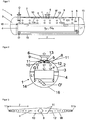
- FIG. 1 shows in connection with the FIGS. 2 and 3 a heat exchanger 1, which has a transverse, (circular) cylindrical shell 2, which limits a shell space 3 of the heat exchanger 1.
- the jacket 2 in this case has a circumferential, cylindrical wall 14, which is delimited by two opposing walls 15 frontally.
- a heat transfer block 4 is arranged in the jacket space 2 enclosed by the jacket 2. This may be a plate heat exchanger that provides multiple parallel heat exchange passages.
- the plate heat exchanger 4 in this case has a plurality of corrugated sheets (so-called fins), which are each arranged between two flat partition plates or plates of the plate heat exchanger 4.
- fins corrugated sheets
- the two outermost layers are formed by cover plates of the plate heat exchanger; towards the sides are between each two adjacent partition plates or separating and cover plates end strips (so-called "side bars") provided.
- the jacket space 3 is filled with a first medium F1 during operation of the heat exchanger 1, so that a liquid phase L1 of the first medium F1 forms a bath surrounding the heat transfer block or plate heat exchanger 4, with a gaseous phase G1 of the first medium forming during operation F1 above the liquid phase L1 in the mantle space 3 can collect.
- the first medium (liquid phase L1) F1 can ascend in the heat transfer block 4 (in associated heat exchange passages) and is thereby indirectly controlled by a second medium F2 to be cooled, which is cross-flown to the first medium F1 in associated heat exchange passages of the heat transfer block 4 Heat transfer partially evaporated.
- the resulting gaseous phase G1 of the first medium F1 can escape at an upper end of the block 4 and rises in the shell space 3 of the heat exchanger 1 with a certain speed field v.
- the second medium F2 is passed through a suitable inlet O (eg via a nozzle on a header) in the heat transfer block or plate heat exchanger 4 and after passing through the associated heat exchange passages via a sequence O '(eg via a corresponding header and a connecting piece ) withdrawn from the block 4.
- a suitable inlet O eg via a nozzle on a header
- O ' e.g via a corresponding header and a connecting piece
- a box-shaped collecting channel 5 which extends along an extension direction 7, is arranged on an inner side 2a of the jacket 2 facing the jacket space 3.
- the collecting channel 5 is designed, in particular, longitudinally extended and accordingly has a greater extent along the direction of extent 7 than transversely to that direction of extent 7.
- the collecting channel 5 furthermore has a wall W which delimits an interior I of the collecting channel 5, through which the gaseous phase G1 of the first medium F1 is withdrawn from the jacket space 3.
- the wall W has in detail an upper side 9, which in the present case is formed by the jacket 2, as well as two side walls 11 extending therefrom, which extend along the extension direction 7 and via a bottom (lower side) 10 of the collecting channel 5 lying opposite the upper side 9 are connected.
- slot-shaped inlet openings 12 are now provided on the side walls 11 and / or the bottom 10 of the collecting channel (in the present case slot-shaped inlet openings on the bottom 10) through which the gaseous phase G1 can enter the collection channel 5.
- the inlet openings 12 are arranged side by side along the extension direction 7, wherein the distance between adjacent inlet openings 13 along the extension direction 7, starting from the outlet nozzle 6 to the two end faces 11 a, 11 b of the collecting channel 5 towards each preferably decreases.
- the longitudinal axes of these inlet openings 12 in each case extend transversely to the direction of extension 7 of the collecting channel 5.
- circular inlet openings 13 are provided on the side walls 11 and / or the underside 10 of the collecting channel 5 (in the present case circular inlet openings 13 on the side walls 11), which are likewise arranged alongside one another along the extension direction 7.
- the distance between adjacent inlet openings 12 along the extension direction 7, starting from the outlet nozzle 6 to the two end faces 11 a, 11 b of the collecting channel 5 towards each preferably decreases.
- the collecting channel 5 is further connected to an outlet nozzle 6 of the jacket 2, which opens into the upper side 9 of the collecting channel 5, so that the gaseous phase G1 of the first medium F1, which has reached the interior I of the collecting channel 5 via the inlet openings 12, 13 Collection channel 5 can be deducted via the outlet nozzle 6.
- the outlet nozzle 6 is preferably arranged centrally along the direction of extent 7 on the collecting channel 5, wherein the underside 10 of the collecting channel 5 preferably has two portions 10a, 10b sloping towards the outlet nozzle 6, which preferably meet below the outlet nozzle 6.
- the cross-section of the collecting channel 5 increases (widened) in each case from the end faces 11 a, 11 b of the collecting channel 5, starting in the direction of the outlet nozzle 6, in the collecting channel 5 (and in the shell space 3) as homogeneous as possible velocity field v of the gaseous phase G1 of first medium F1.
Description
Die Erfindung betrifft einen Wärmeübertrager gemäß dem Oberbegriff des Anspruchs 1. Ein derartiger Wärmeübertrager ist aus
In "The standards of the brazed aluminium plate-fin heat exchanger manufacturer's association (ALPEMA)", dritte Ausgabe, 2010, Seite 67 ist in Figur 9-1 ein sogenannter "core-in-shell"- oder "block-in-shell"-Wärmeübertrager gezeigt. Er weist einen Mantel ("shell") auf, der einen Mantelraum umschließt, sowie mindestens einen im Mantelraum angeordneten Wärmeübertragungsblock ("core"), der als Plattenwärmetauscher ausgebildet ist.In "The standards of the brazed aluminum plate-fin heat exchanger manufacturer's association (ALPEMA)", third edition, 2010, page 67 is in Figure 9-1 a so-called "core-in-shell" - or "block-in-shell "Heat exchanger shown. It has a shell, which encloses a jacket space, and at least one heat transfer block ("core") arranged in the jacket space, which is designed as a plate heat exchanger.
Mit einem solchen Wärmeübertrager kann insbesondere ein erstes Medium, das beim Betrieb des Wärmeübertragers ein den Wärmeübertragungsblock umgebendes Bad ausbildet und in dem Wärmeübertragungsblock (entlang der Vertikalen) von unten nach oben aufsteigt (Thermosiphon-Effekt), in eine indirekte Wärmeübertragung mit einem zweiten Medium gebracht werden (z.B. eine zu verflüssigende gasförmige Phase oder eine zu kühlende flüssige Phase), das bevorzugt im Gegenstrom oder Kreuzstrom zum ersten Medium im Wärmeübertragungsblock geführt wird. Eine hierbei entstehende gasförmige Phase des ersten Mediums sammelt sich im Mantelraum oberhalb des Wärmeübertragungsblocks und wird über zumindest einen am Mantel vorgesehenen Austrittsstutzen abgezogen und über einen außerhalb des Mantels vorgesehenen (externen) Sammelkanal eventuell weiteren Prozessschritten zugeleitet.In particular, a first medium, which forms a bath surrounding the heat transfer block during operation of the heat exchanger and rises from bottom to top in the heat transfer block (along the vertical) (thermosiphon effect), can be brought into indirect heat transfer with a second medium (For example, to be liquefied gaseous phase or a liquid phase to be cooled), which is preferably performed in countercurrent or cross flow to the first medium in the heat transfer block. A resulting gaseous phase of the first medium collects in the jacket space above the heat transfer block and is withdrawn via at least one outlet nozzle provided on the jacket and optionally fed to further process steps via a (external) collecting duct provided outside the jacket.
Durch diese Art des Abzuges der gasförmigen Phase entwickelt sich im Mantelraum ein heterogenes Geschwindigkeitsfeld der zum Austrittsstutzen strebenden gasförmigen Phase, das die Güte der Gas-Flüssigkeitstrennung im Mantelraum beeinträchtigt. Diesem Effekt kann durch eine Variation der Zahl oder der Größe der Austrittsstutzen nur begrenzt entgegengewirkt werden, zumal die Strömungseigenschaften im externen Sammelkanal ebenfalls auf das Geschwindigkeitsfeld der gasförmigen Phase im Mantelraum zurückwirken. Darüber hinaus sind die Austrittstutzen drucktragende Bestandteile eines ("core-in-shell") Wärmeübertragers der eingangs genannten Art und sind daher konstruktiv aufwändig, was erhöhte Fertigungskosten im Falle mehrerer Austrittsstutzen mit sich bringt. Des Weiteren wird durch die Festlegung der Austrittsstutzenposition an der Oberseite des Mantels ein Freiheitsgrad bei der Konstruktion der umgebenden Bauteile (z.B. Coldbox, Feldverrohrung) genommen.As a result of this type of withdrawal of the gaseous phase, a heterogeneous velocity field of the gaseous phase aspiring to the outlet nozzle, which impairs the quality of the gas-liquid separation in the jacket space, develops in the jacket space. This effect can be counteracted only to a limited extent by a variation of the number or the size of the outlet nozzles, especially as the flow properties in the external collector channel also have an effect on the velocity field of the gaseous phase in the jacket space. In addition, the outlet nozzle pressure-bearing components of a ("core-in-shell") heat exchanger of the type mentioned and are therefore structurally complex, which brings increased manufacturing costs in the case of multiple outlet pipe with it. Furthermore, the definition of the outlet nozzle position at the top of the shell, a degree of freedom in the construction of the surrounding components (eg, cold box, field piping) is taken.
Hiervon ausgehend liegt daher der vorliegenden Erfindung die Aufgabe zugrunde, einen Wärmeübertrager bereitzustellen, der im Hinblick auf die vorgenannte Problematik verbessert ist.Proceeding from this, therefore, the present invention seeks to provide a heat exchanger, which is improved in view of the aforementioned problem.
Dieses Problem wird durch einen Wärmeübertrager mit den Merkmalen des Anspruchs 1 gelöst.This problem is solved by a heat exchanger with the features of
Demnach wird ein Wärmeübertrager zur indirekten Wärmeübertragung zwischen einem ersten Medium und einem zweiten Medium bereitgestellt, mit:
- einem Mantel, der einen Mantelraum zur Aufnahme des ersten Mediums aufweist,
- zumindest einem im Mantelraum angeordneten Wärmeübertragungsblock, der bei einem bestimmungsgemäßen Betrieb vom ersten Medium umgeben ist, wobei der Wärmeübertragungsblock dazu ausgebildet ist, das zweite Medium gegen das erste Medium abzukühlen und / oder zumindest teilweise zu verflüssigen, so dass sich im Mantelraum eine gasförmige Phase des ersten Mediums bildet,
- wobei zum Abziehen der gasförmigen Phase des ersten Mediums aus dem Mantelraum ein im Mantelraum befindlicher Sammelkanal vorgesehen ist, der sich entlang einer Erstreckungsrichtung erstreckt, die parallel zur Längsachse des Mantels ausgerichtet ist,
- und wobei der mindestens eine Wärmeübertragungsblock ein Plattenwärmetauscher ist,
- und wobei der Sammelkanal mit zumindest einem am Mantel vorgesehenen Austrittsstutzen verbunden ist, so dass die gasförmige Phase des ersten Mediums durch den Sammelkanal über den zumindest einen Austrittsstutzen aus dem Mantelraum abziehbar ist,
- und wobei der Sammelkanal zwei Stirnseiten aufweist, die entlang der Erstreckungsrichtung des Sammelkanals einander gegenüberliegen.
- a jacket, which has a jacket space for receiving the first medium,
- at least one arranged in the shell space heat transfer block, which is surrounded by the first medium in a normal operation, wherein the heat transfer block is adapted to cool the second medium against the first medium and / or at least partially liquefy, so that in the shell space, a gaseous phase of first medium forms,
- wherein for withdrawing the gaseous phase of the first medium from the jacket space, there is provided a collecting channel located in the jacket space, which extends along an extension direction, which is aligned parallel to the longitudinal axis of the jacket,
- and wherein the at least one heat transfer block is a plate heat exchanger,
- and wherein the collecting channel is connected to at least one outlet nozzle provided on the jacket, so that the gaseous phase of the first medium can be withdrawn from the jacket space through the collecting channel via the at least one outlet nozzle,
- and wherein the collecting channel has two end faces which face each other along the extending direction of the collecting channel.
Erfindungsgemäß ist des Weiteren vorgesehen,
- dass der Sammelkanal (5) quer zur Erstreckungsrichtung (7) einen Querschnitt aufweist, der sich zum Austrittsstutzen (6) hin vergrößert und
- dass der Sammelkanal (5) zum Abziehen der gasförmigen Phase eine Mehrzahl an Eintrittsöffnungen (12, 13) aufweist, wobei die Abstände benachbarter Eintrittsöffnungen zur jeweiligen Stirnseite (11 a, 11 b) des Sammelkanals (5) hin abnehmen.
- that the collecting channel (5) transversely to the extension direction (7) has a cross-section which increases towards the outlet nozzle (6) and
- in that the collecting channel (5) for withdrawing the gaseous phase has a plurality of inlet openings (12, 13), wherein the distances of adjacent inlet openings to the respective end face (11 a, 11 b) of the collecting channel (5) decrease.
Gemäß einer Ausgestaltung der Erfindung können im Mantelraum auch mehrere Wärmeübertragungsblöcke bzw. Plattenwärmetauscher vorgesehen sein, die z.B. parallel oder in Serie betrieben werden können.According to one embodiment of the invention, a plurality of heat transfer blocks or plate heat exchangers may also be provided in the shell space. can be operated in parallel or in series.
Derartige Plattenwärmetauscher weisen in der Regel eine Mehrzahl an parallel zueinander angeordneten Platten bzw. Blechen auf, die eine Vielzahl von Wärmeaustauschpassagen für am Wärmetausch beteiligte Medien bilden. Eine bevorzugte Ausführungsform eines Plattenwärmetauschers weist eine Mehrzahl an gewellten Blechen auf (sogenannte Fins), die jeweils zwischen zwei parallelen Trennplatten bzw. -blechen des Plattenwärmetauschers angeordnet sind, wobei die beiden äußersten Lagen des Plattenwärmetauschers durch Deckplatten gebildet sind. Auf diese Weise werden zwischen je zwei Trennplatten bzw. zwischen einer Trennplatte und einer Deckplatte aufgrund des jeweils dazwischen angeordneten Fins eine Vielzahl an parallelen Kanälen bzw. eine Wärmeaustauschpassage gebildet, durch die ein Medium strömen kann. In benachbarten Wärmeaustauschpassagen strömende Medien können daher indirekt Wärme austauschen. Zu den Seiten hin sind zwischen je zwei benachbarten Trennplatten bzw. zwischen einer Deckplatte und der benachbarten Trennplatte vorzugsweise Abschlussleisten (so genannte Side Bars) zum Verschließen der jeweiligen Wärmeaustauschpassage vorgesehen. Die Deckplatten, Trennplatten, Fins und Side Bars sind vorzugsweise aus Aluminium gefertigt und werden z.B. in einem Ofen miteinander verlötet. Über entsprechende Header mit Stutzen können Medien in die Wärmeaustauschpassagen eingeleitet bzw. aus diesen abgezogen werden.Such plate heat exchangers generally have a plurality of parallel plates or plates, which form a plurality of heat exchange passages for media involved in the heat exchange. A preferred embodiment of a plate heat exchanger has a plurality of corrugated sheets (so-called fins), each disposed between two parallel separator plates or plates of the plate heat exchanger, wherein the two outermost layers of the plate heat exchanger are formed by cover plates. In this way, a plurality of parallel channels or a heat exchange passage are formed between each two partition plates or between a partition plate and a cover plate due to the respective interposed fin, through which a medium can flow. Therefore, media flowing in adjacent heat exchange passages can exchange heat indirectly. To the sides are provided between each two adjacent partition plates or between a cover plate and the adjacent partition plate preferably end strips (so-called side bars) for closing the respective heat exchange passage. The cover plates, separator plates, fins and side bars are preferably made of aluminum manufactured and are soldered together, for example in an oven. Via appropriate headers with nozzles media can be introduced into the heat exchange passages or subtracted from these.
Der Mantel des Wärmeübertragers kann insbesondere eine umlaufende, (kreis)zylindrische Wandung aufweisen, die bei einem bestimmungsgemäß angeordneten Zustand des Wärmeübertragers vorzugsweise so ausgerichtet ist, dass sich die Längsachse (Zylinderachse) der Wandung bzw. des Mantels entlang der Horizontalen erstreckt. Stirnseitig weist der Mantel bevorzugt einander gegenüberliegende, mit jener Wandung verbundene Wände auf, die sich quer zur Horizontalen bzw. Längsachse erstrecken.The jacket of the heat exchanger can in particular have a circumferential, (circular) cylindrical wall, which is preferably aligned in an intended arranged state of the heat exchanger so that the longitudinal axis (cylinder axis) of the wall or the jacket extends along the horizontal. At the front, the jacket preferably has mutually opposite walls connected to that wall, which extend transversely to the horizontal or longitudinal axis.
Gemäß der vorliegenden Erfindung ist der besagte Sammelkanal zum Abziehen der gasförmigen Phase des ersten Mediums mit einem Austrittsstutzen, der insbesondere an einer Oberseite des Mantels angeordnet ist, strömungsleitend verbunden (z.B. über eine Leitung), so dass die gasförmige Phase des ersten Mediums über jenen Austrittsstutzen aus dem Mantelraum abgezogen werden kann.According to the present invention, said collecting channel for withdrawing the gaseous phase of the first medium with an outlet nozzle, which is arranged in particular on an upper side of the jacket, is conductively connected (eg via a line) so that the gaseous phase of the first medium is above those outlet nozzles can be deducted from the shell space.
Erfindungsgemäß ist vorgesehen, dass sich der Sammelkanal entlang einer Erstreckungsrichtung erstreckt, die parallel zur Längsachse (Zylinderachse) des Mantels bzw. entlang der Horizontalen ausgerichtet ist, und dabei bevorzugt quer zur besagten Erstreckungsrichtung (Längsachse) vorzugsweise einen rohrförmigen (kreisförmigen) oder einen kastenförmigen (rechteckförmigen) Querschnitt aufweist.According to the invention, the collecting channel extends along an extension direction that is parallel to the longitudinal axis (cylinder axis) of the shell or along the horizontal, and preferably preferably a tubular (circular) or a box-shaped (transverse) to said extension direction (longitudinal axis). rectangular) cross section.
Vorzugsweise ist der Sammelkanal (bezogen auf einen bestimmungsgemäß angeordneten Zustand des Wärmeübertragers) entlang der Vertikalen oberhalb des Flüssigkeitsspiegels des ersten Mediums bzw. oberhalb des Wärmeübertragungsblocks im Mantelraum angeordnet, so dass die (vom Wärmeübertragungsblock) aufsteigende gasförmige Phase des ersten Mediums auf den Sammelkanal trifft.Preferably, the collecting channel is arranged along the vertical above the liquid level of the first medium or above the heat transfer block in the jacket space, so that the gaseous phase of the first medium rising from the heat transfer block strikes the collecting channel (relative to a condition of the heat exchanger arranged as intended).
Der Sammelkanal weist bevorzugt eine Wandung auf, die einen Innenraum des Sammelkanals umschließt, in dem die gasförmige Phase zu dem besagten Austrittstutzen strömen kann. Dabei wird derjenige Bereich jener Wandung des Sammelkanals, der zu einer Oberseite des Wärmeübertragers weist bzw. entlang der Vertikalen nach oben weist, als Oberseite des Sammelkanals bezeichnet, und der gegenüberliegende Bereich der Wandung des Sammelkanals, der zur Unterseite des Wärmeübertragers weist, stellt entsprechend die Unterseite des Sammelkanals dar. Die Ober- und Unterseite des Sammelkanals werden bevorzugt durch entlang der Längsachse des Mantels erstreckte Seitenwände des Sammelkanals miteinander verbunden.The collecting channel preferably has a wall which encloses an interior of the collecting channel, in which the gaseous phase can flow to the said outlet connection. In this case, that portion of that wall of the collecting channel, which faces an upper side of the heat exchanger or along the Vertical upwards, referred to as the top of the collecting channel, and the opposite region of the wall of the collecting channel, which faces the bottom of the heat exchanger, corresponding to the bottom of the collecting channel. The top and bottom of the collecting channel are preferably through along the longitudinal axis of the shell extended side walls of the collecting channel interconnected.
Stirnseitig ist der Sammelkanal durch einander gegenüberliegende Stirnseiten begrenzt, die jeweils die Ober-, die Unterseite und die Seitenwände miteinander verbinden.The end face of the collecting channel is bounded by opposite end faces, which connect the top, bottom and side walls together.
Eine Variante der Erfindung sieht weiterhin vor, dass eine oder mehrere der vorgenannten Bereiche der Wandung des Sammelkanals durch den Mantel des Wärmeübertragers ausgebildet werden können. Bevorzugt wird die Oberseite des Sammelkanals bzw. die Oberseite der Wandung des Sammelkanals durch den Mantel gebildet. Die Seitenwände und Stirnseiten sind also entsprechend vom Mantelraum her an den Mantel angesetzt.A variant of the invention further provides that one or more of the aforementioned regions of the wall of the collecting channel can be formed by the jacket of the heat exchanger. Preferably, the top of the collecting channel or the top of the wall of the collecting channel is formed by the jacket. The side walls and end faces are therefore attached to the jacket corresponding to the jacket space.
Zum Abziehen der gasförmigen Phase weist der Sammelkanal erfindungsgemäß eine Mehrzahl an Eintrittsöffnungen auf, die insbesondere an der Unterseite (Boden) des Sammelkanals sowie ggf. an den einander gegenüberliegenden Seitenwänden des Sammelkanals ausgebildet sind. Dabei sind die am Boden des Sammelkanals ausgebildeten Eintrittsöffnungen vorzugsweise schlitzförmig ausgebildet, wohingegen an den Seitenwänden vorgesehene Eintrittsöffnungen vorzugsweise eine kreisförmige Kontur aufweisen (z.B. Bohrungen).To remove the gaseous phase, the collecting channel according to the invention a plurality of inlet openings, which are formed in particular on the bottom (bottom) of the collecting channel and possibly on the opposite side walls of the collecting channel. In this case, the inlet openings formed at the bottom of the collecting channel are preferably slit-shaped, whereas inlet openings provided on the side walls preferably have a circular contour (for example bores).
Erfindungsgemäß ist vorgesehen, dass die Abstände benachbarter Eintrittsöffnungen, und zwar insbesondere die Abstände der an der Unterseite vorgesehenen Eintrittsöffnungen, zur jeweiligen Stirnseite des Sammelkanals hin abnehmen. D.h., das zwei benachbarte Eintrittsöffnungen, die näher an einer der Stirnseiten des Sammelkanals gelegen sind, vorzugsweise einen geringeren Abstand zueinander entlang der Erstreckungsrichtung des Sammelkanals aufweisen als zwei benachbarte Eintrittsöffnungen, die eher zur Mitte des Sammelkanals hin (bezogen auf die Erstreckungsrichtung) angeordnet sind.According to the invention, it is provided that the distances between adjacent inlet openings, and in particular the distances between the inlet openings provided on the underside, decrease towards the respective end face of the collecting channel. That is, the two adjacent entrance openings, which are located closer to one of the end faces of the collecting channel, preferably have a smaller distance from each other along the extension direction of the collecting channel than two adjacent inlet openings, which are arranged towards the center of the collecting channel (with respect to the extension direction).
Bevorzugt sind die Anzahl, Verteilung, Größe und/oder Form der Eintrittsöffnungen so gewählt, dass sich das Geschwindigkeitsfeld der gasförmigen Phase des ersten Mediums im Sammelkanal betragsmäßig möglichst gleichförmig einstellt.
Weiterhin ist gemäß einem Aspekt der Erfindung die Querschnittsfläche (und ggf. Kontur) des Sammelkanals (in einer Ebene senkrecht zur Erstreckungsrichtung des Sammelkanals) derart gewählt, dass sich im Sammelkanal und im Mantelraum ein möglichst gleichförmiges Strömungsfeld der gasförmigen Phase des ersten Mediums einstellt. Bevorzugt wird dies durch eine Erweiterung / Vergrößerung des Querschnitts des Sammelkanals hin zum Austrittsstutzen und/oder durch eine definierte Anordnung, Form und Größe der Eintrittsöffnungen am Sammelkanal unterstützt.Preferably, the number, distribution, size and / or shape of the inlet openings are chosen so that the velocity field of the gaseous phase of the first medium in the collecting channel sets the amount as uniform as possible.
Furthermore, according to one aspect of the invention, the cross-sectional area (and possibly contour) of the collecting channel (in a plane perpendicular to the direction of extension of the collecting channel) is selected such that a uniform as possible flow field of the gaseous phase of the first medium sets in the collecting channel and in the shell space. This is preferably supported by an enlargement / enlargement of the cross section of the collecting channel towards the outlet nozzle and / or by a defined arrangement, shape and size of the inlet openings on the collecting channel.
Weiterhin kann der Mantel natürlich auch eine Mehrzahl an Austrittsstutzen aufweisen, die mit einem wie vorstehend beschriebenen Sammelkanal oder gegebenenfalls mit mehreren Sammelkanälen der vorstehend beschriebenen Art verbunden sein können.Furthermore, the sheath can of course also have a plurality of outlet stubs, which may be connected to a collecting channel as described above or possibly to a plurality of collecting channels of the type described above.
Die Positionen, Dimensionen und Ausrichtungen dieser Sammelkanäle werden dabei vorzugsweise so gewählt, dass sich das Geschwindigkeitsfeld der gasförmigen Phase des ersten Mediums im Mantelraum und in dem jeweiligen Sammelkanal betragsmäßig möglichst gleichförmig einstellt.The positions, dimensions and orientations of these collecting ducts are preferably selected such that the velocity field of the gaseous phase of the first medium in the jacket space and in the respective collecting duct is adjusted as uniformly as possible in terms of magnitude.
Weiterhin kann der mindestens eine Austrittstutzen (oder auch mehrere Austrittsstutzen) erfindungsgemäß an einem oberen, einem unteren, einem seitlichen Bereich der umlaufenden Wandung des Mantels oder an einer der stirnseitigen Wände des Mantels angeordnet sein.Furthermore, according to the invention, the at least one outlet nozzle (or even several outlet nozzle) can be arranged on an upper, a lower, a lateral region of the circumferential wall of the jacket or on one of the frontal walls of the jacket.
Weitere Einzelheiten und Vorteile der Erfindung sollen durch die nachfolgenden Figurenbeschreibungen von Ausführungsbeispielen anhand der Figuren erläutert werden. Vorteilhafte Ausführungsformen der Erfindung sind außerdem in den Unteransprüchen angegeben.Further details and advantages of the invention will be explained by the following description of exemplary embodiments with reference to the figures. Advantageous embodiments of the invention are also specified in the subclaims.
Es zeigen:
- Fig. 1
- eine Schnittansicht eines erfindungsgemäßen Wärmeübertragers
- Fig. 2
- eine weitere Schnittansicht des Wärmeübertragers gemäß
Figur 1 ; und - Fig. 3
- eine Schnittansicht eines Sammelkanals des Wärmeübertrager gemäß
Figuren 1 .und 2
- Fig. 1
- a sectional view of a heat exchanger according to the invention
- Fig. 2
- a further sectional view of the heat exchanger according to
FIG. 1 ; and - Fig. 3
- a sectional view of a collecting channel of the heat exchanger according to
Figures 1 and 2 ,
In dem vom Mantel 2 umschlossenen Mantelraum 3 ist ein Wärmeübertragungsblock 4 angeordnet. Hierbei kann es sich um einen Plattenwärmetauscher handeln, der mehrere parallele Wärmeaustauschpassagen bereitstellt.In the
Der Plattenwärmetauscher 4 weist dabei eine Mehrzahl an gewellten Blechen auf (sogenannte Fins), die jeweils zwischen zwei ebenen Trennplatten bzw. -blechen des Plattenwärmetauschers 4 angeordnet sind. Auf diese Weise werden zwischen je zwei Trennplatten (bzw. eine Trennplatte und einer Deckplatte, siehe unten) eine Vielzahl an parallelen Kanälen bzw. eine Wärmeaustauschpassage gebildet, durch die das jeweilige Medium strömen kann. Die beiden äußersten Lagen werden durch Deckplatten des Plattenwärmetauschers gebildet; zu den Seiten hin sind zwischen je zwei benachbarten Trennplatten bzw. Trenn- und Deckplatten Abschlussleisten (so genannte "side bars") vorgesehen.The
Der Mantelraum 3 ist während eines Betriebes des Wärmeübertragers 1 mit einem ersten Medium F1 befüllt, so dass eine flüssigen Phase L1 des ersten Mediums F1 ein den Wärmeübertragungsblock bzw. Plattenwärmetauscher 4 umgebendes Bad ausbildet, wobei sich eine beim Betrieb bildende gasförmige Phase G1 des ersten Mediums F1 oberhalb der flüssigen Phase L1 im Mantelraum 3 sammeln kann.The
Das erste Medium (flüssige Phase L1) F1 kann in dem Wärmeübertragungsblock 4 (in zugeordneten Wärmeaustauschpassagen) aufsteigen und wird dabei durch ein zu kühlendes zweites Medium F2, das z.B. im Kreuzstrom zum ersten Medium F1 in zugeordneten Wärmeaustauschpassagen des Wärmeübertragungsblocks 4 geführt wird, durch indirekte Wärmeübertragung teilweise verdampft. Die hierbei entstehende gasförmige Phase G1 des ersten Mediums F1 kann an einem oberen Ende des Blocks 4 austreten und steigt im Mantelraum 3 des Wärmeübertragers 1 mit einem bestimmten Geschwindigkeitsfeld v auf.The first medium (liquid phase L1) F1 can ascend in the heat transfer block 4 (in associated heat exchange passages) and is thereby indirectly controlled by a second medium F2 to be cooled, which is cross-flown to the first medium F1 in associated heat exchange passages of the
Das zweite Medium F2 wird über einen geeigneten Zulauf O (z.B. über einen Stutzen an einem Header) in den Wärmeübertragungsblock bzw. Plattenwärmetauscher 4 geleitet und nach einem Durchlaufen der zugeordneten Wärmeaustauschpassagen über einen Ablauf O' (z.B. über einen entsprechenden Header und einem damit verbundenen Stutzen) aus dem Block 4 abgezogen.The second medium F2 is passed through a suitable inlet O (eg via a nozzle on a header) in the heat transfer block or
An der Oberseite 8 des Wärmeübertragers 1 ist an einer dem Mantelraum 3 zugewandten Innenseite 2a des Mantels 2 ein kastenförmiger Sammelkanal 5 angeordnet, der sich entlang einer Erstreckungsrichtung 7 erstreckt. Der Sammelkanal 5 ist dabei insbesondere längserstreckt ausgebildet und weist entsprechend entlang der Erstreckungsrichtung 7 eine größere Ausdehnung auf, als quer zu jener Erstreckungsrichtung 7.On the
Der Sammelkanal 5 weist des Weiteren eine Wandung W auf, die einen Innenraum I des Sammelkanals 5 begrenzt, durch den hindurch die gasförmige Phase G1 des ersten Mediums F1 aus dem Mantelraum 3 abgezogen wird. Die Wandung W weist im Einzelnen eine Oberseite 9 auf, die vorliegend durch den Mantel 2 gebildet wird, sowie zwei davon abgehende Seitenwände 11, die sich entlang der Erstreckungsrichtung 7 erstrecken und über einen der Oberseite 9 gegenüberliegenden Boden (Unterseite) 10 des Sammelkanals 5 miteinander verbunden sind. Des Weiteren weist der Sammelkanal 5 bzw. dessen Wandung W zwei Stirnseiten 11 a, 11 b auf, die einander entlang der Erstreckungsrichtung 7 gegenüberliegen.The collecting
Zum Abziehen der gasförmigen Phase G1 des ersten Mediums F1 aus dem Mantelraum 3 sind nun an den Seitenwänden 11 und/oder der Unterseite 10 des Sammelkanals 5 schlitzförmige Eintrittsöffnungen 12 vorgesehen (vorliegend schlitzförmige Eintrittsöffnungen an der Unterseite 10), durch die hindurch die gasförmige Phase G1 in den Sammelkanal 5 eintreten kann. Die Eintrittsöffnungen 12 sind dabei entlang der Erstreckungsrichtung 7 nebeneinander angeordnet, wobei der Abstand zwischen benachbarten Eintrittsöffnungen 13 entlang der Erstreckungsrichtung 7 ausgehend vom Austrittsstutzen 6 zu den beiden Stirnseiten 11 a, 11 b des Sammelkanals 5 hin jeweils bevorzugt abnimmt. Die Längsachsen dieser Eintrittsöffnungen 12 verlaufen dabei jeweils quer zur Erstreckungsrichtung 7 des Sammelkanals 5.For withdrawing the gaseous phase G1 of the first medium F1 from the
Des Weiteren sind an den Seitenwänden 11 und/oder der Unterseite 10 des Sammelkanals 5 jeweils kreisförmige Eintrittsöffnungen 13 vorgesehen (vorliegend kreisförmige Eintrittsöffnungen 13 an den Seitenwänden 11), die ebenfalls entlang der Erstreckungsrichtung 7 nebeneinander angeordnet sind. Auch hier nimmt der Abstand zwischen benachbarten Eintrittsöffnungen 12 entlang der Erstreckungsrichtung 7 ausgehend vom Austrittsstutzen 6 zu den beiden Stirnseiten 11a, 11 b des Sammelkanals 5 hin jeweils bevorzugt ab.Furthermore, in each case
Der Sammelkanal 5 ist ferner mit einem Austrittstutzen 6 des Mantels 2 verbunden, der in die Oberseite 9 des Sammelkanals 5 einmündet, so dass die über die Eintrittsöffnungen 12, 13 in den Innenraum I des Sammelkanals 5 gelangte gasförmige Phase G1 des ersten Mediums F1 aus dem Sammelkanal 5 über den Austrittstutzen 6 abgezogen werden kann.The collecting
Der Austrittstutzen 6 ist entlang der Erstreckungsrichtung 7 vorzugsweise mittig am Sammelkanal 5 angeordnet, wobei die Unterseite 10 des Sammelkanals 5 bevorzugt zwei zum Austrittsstutzen 6 hin abfallende Abschnitte 10a, 10b aufweist, die sich vorzugsweise unterhalb des Austrittsstutzens 6 treffen.The
Der Querschnitt des Sammelkanals 5 vergrößert (verbreitert) sich jeweils von den Stirnseiten 11 a, 11 b des Sammelkanales 5 ausgehend in Richtung auf den Austrittsstutzen 6, um im Sammelkanal 5 (und im Mantelraum 3) ein möglichst homogenes Geschwindigkeitsfeld v der gasförmigen Phase G1 des ersten Mediums F1 zu erhalten.
Claims (13)
- Heat exchanger (1) for the indirect heat transfer between a first medium (F1) and a second medium (F2), with:- a shell (2) which has a shell space (3) for receiving the first medium (F1),- at least one heat transfer block (4) which is arranged in the shell space (3) and enveloped by the first medium (F1) during a design-specified operation, wherein the heat transfer block (4) is designed for cooling and/or for at least partially liquefying the second medium (F2) against the first medium (F1) so that a gaseous phase of the first medium (G1) is formed in the shell space (3),- wherein for extracting the gaseous phase of the first medium (G1) from the shell space (3), provision is made for a collecting channel (5) which is located in the shell space (3) and extends along a direction of extension which is oriented parallel to the longitudinal axis of the shell,- and wherein the at least one heat transfer block (4) is a plate heat exchanger,- and wherein the collecting channel (5) is connected to at least one outlet connector (6) which is provided on the shell (2) so that the gaseous phase of the first medium (G1) can be extracted from the shell space (3) through the collecting channel (5) via the at least one outlet connector (6),- and wherein the collecting channel (5) has two end faces (11a, 11b) which lie mutually opposite along the direction of extension of the collecting channel (5),characterized in that- the collecting channel (5) has a cross section transversely to the direction of extension (7) which increases towards the outlet connector (6) and- the collecting channel (5) has a multiplicity of inlet openings (12, 13) for extracting the gaseous phase, wherein the spacings of adjacent inlet openings decrease towards the respective end face (11a, 11b) of the collecting channel (5).
- Heat exchanger according to Claim 1, characterized in that the heat transfer block (4) is designed so that the first medium (F1) can rise in the heat transfer block (4) during operation of the heat exchanger (1), wherein the heat transfer block (4) is especially designed for conducting the second medium (F2) in counterflow or crossflow to the first medium (F1) in the heat transfer block (4).
- Heat exchanger according to Claim 1 or 2, characterized in that a multiplicity of heat transfer blocks (4) in the form of plate heat exchangers are arranged in the shell space.
- Heat exchanger according to one of the preceding claims, characterized in that the collecting channel (5) has a wall (W) which defines an interior space (I) of the collecting channel (5) in which the gaseous phase of the first medium (G1) can flow towards the outlet connector (6), and which extends along the horizontal direction of extension (7) which stretches along an upper side (8) of the shell (2).
- Heat exchanger according to Claim 4, characterized in that the collecting channel (5) has a box-shaped or tubular cross section transversely to the direction of extension (7).
- Heat exchanger according to one of Claims 4 and 5, characterized in that the wall (W) of the collecting channel (5) has an upper side (9) and an oppositely disposed lower side (10), wherein the upper side (9) and the lower side (10) are interconnected via mutually opposite sidewalls (11) of the wall (W) of the collecting channel (5).
- Heat exchanger according to Claim 6, characterized in that one section of the wall (W) of the collecting channel (5), especially an upper side (9) of the wall (W), is formed by the shell (2).
- Heat exchanger according to Claim 6 or 7, characterized in that the lower side (10) and/or the sidewalls (11) of the collecting channel (5) have a multiplicity of especially slot-like inlet openings (12) through which the gaseous phase of the first medium (G1) can flow into the collecting channel (5).
- Heat exchanger according to one of Claims 6 to 8, characterized in that the lower side (10) and/or the sidewalls (11) of the collecting channel (5) have a multiplicity of in particular circular inlet openings (13) through which the gaseous phase of the first medium (G1) can flow into the collecting channel (5).
- Heat exchanger according to one of the preceding claims, characterized in that the heat exchanger (1) has additional outlet connectors (6) which are interconnected via the collecting channel (5).
- Heat exchanger according to one of the preceding claims, characterized in that the heat exchanger (1) has a large number of collecting channels (5) which are connected in each case to at least one outlet connector (6).
- Heat exchanger according to one of the preceding claims, characterized in that the shell (2) has a cylindrical encompassing wall (14) transversely to the direction of extension (7), which interconnects the two end-face walls (15) of the shell (2).
- Heat exchanger according to Claim 12, characterized in that the at least one outlet connector (6) is arranged on the encompassing wall (W) of the shell (2), especially on an upper section, a side section or a lower section (8, 16) of the wall (14) of the shell (2), or in that the at least one outlet connector (6) is arranged on one of the end-face walls (15) of the shell (2).
Applications Claiming Priority (2)
| Application Number | Priority Date | Filing Date | Title |
|---|---|---|---|
| DE102012011328A DE102012011328A1 (en) | 2012-06-06 | 2012-06-06 | Heat exchanger |
| PCT/EP2013/001670 WO2013182314A1 (en) | 2012-06-06 | 2013-06-06 | Heat exchanger |
Publications (2)
| Publication Number | Publication Date |
|---|---|
| EP2859295A1 EP2859295A1 (en) | 2015-04-15 |
| EP2859295B1 true EP2859295B1 (en) | 2016-08-03 |
Family
ID=46758579
Family Applications (1)
| Application Number | Title | Priority Date | Filing Date |
|---|---|---|---|
| EP13730801.1A Not-in-force EP2859295B1 (en) | 2012-06-06 | 2013-06-06 | Heat exchanger |
Country Status (10)
| Country | Link |
|---|---|
| US (1) | US20150153115A1 (en) |
| EP (1) | EP2859295B1 (en) |
| JP (1) | JP6116681B2 (en) |
| KR (1) | KR20150030229A (en) |
| CN (1) | CN104350351B (en) |
| AU (1) | AU2013270937B2 (en) |
| DE (1) | DE102012011328A1 (en) |
| ES (1) | ES2598837T3 (en) |
| MX (1) | MX344387B (en) |
| WO (1) | WO2013182314A1 (en) |
Families Citing this family (10)
| Publication number | Priority date | Publication date | Assignee | Title |
|---|---|---|---|---|
| US10378837B2 (en) * | 2014-05-01 | 2019-08-13 | Conocophillips Company | Liquid drains in core-in-shell heat exchanger |
| JP2016014495A (en) * | 2014-07-01 | 2016-01-28 | ダイキン工業株式会社 | Falling film evaporator |
| FR3038037B1 (en) | 2015-06-29 | 2018-04-20 | Trane International Inc. | SUCTION DUCT AND DUAL SUCTION DUCT FOR AN IMMERSION EVAPORATOR |
| WO2016102045A1 (en) * | 2014-12-23 | 2016-06-30 | Linde Aktiengesellschaft | Core-in-shell heat exchanger comprising a conducting device for better distribution of the medium in the separation chamber |
| US10113806B2 (en) | 2014-12-23 | 2018-10-30 | Linde Aktiengesellschaft | Heat exchanger, in particular block-in-shell heat exchanger comprising a separating unit for separating a gaseous phase from a liquid phase and for distributing the liquid phase |
| CN105509370B (en) * | 2016-01-14 | 2017-11-03 | 北京瑞宝利热能科技有限公司 | A kind of Combined aluminum alloy heat exchanger and its system |
| CN108662812B (en) | 2017-03-31 | 2022-02-18 | 开利公司 | Flow balancer and evaporator having the same |
| EP3629688A1 (en) * | 2018-09-27 | 2020-04-01 | Siemens Aktiengesellschaft | Power converter with a separate interior |
| EP4058714B1 (en) | 2019-11-15 | 2024-01-03 | Linde GmbH | Transition component with insulation |
| US20230392837A1 (en) * | 2022-06-03 | 2023-12-07 | Trane International Inc. | Evaporator charge management and method for controlling the same |
Family Cites Families (31)
| Publication number | Priority date | Publication date | Assignee | Title |
|---|---|---|---|---|
| US2151863A (en) * | 1937-06-15 | 1939-03-28 | Raymond B Millard | Vapor-liquid separator |
| US2384413A (en) * | 1943-11-18 | 1945-09-04 | Worthington Pump & Mach Corp | Cooler or evaporator |
| US2523529A (en) * | 1949-07-01 | 1950-09-26 | Worthington Pump & Mach Corp | Eliminator for refrigeration system evaporators |
| US2602647A (en) * | 1951-03-30 | 1952-07-08 | Standard Oil Co | Tubular contactor with conical distribution plate |
| GB769459A (en) * | 1953-10-16 | 1957-03-06 | Foster Wheeler Ltd | Improved method and apparatus for the purification of liquids by evaporation |
| US3095255A (en) * | 1960-04-25 | 1963-06-25 | Carrier Corp | Heat exchange apparatus of the evaporative type |
| US3267693A (en) * | 1965-06-29 | 1966-08-23 | Westinghouse Electric Corp | Shell-and-tube type liquid chillers |
| JPS4923630Y1 (en) * | 1970-05-26 | 1974-06-25 | ||
| JPS4842099Y1 (en) * | 1972-05-22 | 1973-12-07 | ||
| DE3424916A1 (en) * | 1984-07-06 | 1986-01-16 | Bbc York Kaelte Klima | Refrigerating installation |
| JPS6219689A (en) * | 1985-07-18 | 1987-01-28 | Toshiba Corp | Evaporator for use in non-azetropic mixture medium |
| JPS6399142U (en) * | 1986-12-15 | 1988-06-27 | ||
| JPH0452452A (en) * | 1990-06-21 | 1992-02-20 | Tonen Corp | Producing arrangement for uniform gas-flow |
| US5188911A (en) * | 1991-02-25 | 1993-02-23 | Magnavox Electronic Systems Company | Tapered manifold for batteries requiring forced electrolyte flow |
| DE4126629A1 (en) * | 1991-08-12 | 1993-03-11 | Siemens Ag | SECOND-SIDED HEAT EXHAUST SYSTEM FOR PRESSURE WATER CORE REACTORS |
| US5174121A (en) * | 1991-09-19 | 1992-12-29 | Environmental Water Technology | Purified liquid storage receptacle and a heat transfer assembly and method of heat transfer |
| US5268727A (en) * | 1992-11-13 | 1993-12-07 | Xerox Corporation | Uniform velocity air manifold |
| JP3360343B2 (en) * | 1993-03-23 | 2002-12-24 | ダイキン工業株式会社 | Liquid-filled evaporator |
| CN1116566C (en) * | 1996-07-19 | 2003-07-30 | 美国标准公司 | Evaporator refrigerant distributor |
| US6293112B1 (en) * | 1999-12-17 | 2001-09-25 | American Standard International Inc. | Falling film evaporator for a vapor compression refrigeration chiller |
| JP4192413B2 (en) * | 2000-09-06 | 2008-12-10 | 株式会社Ihi | Ice cooler supercooler |
| US7017656B2 (en) * | 2001-05-24 | 2006-03-28 | Honeywell International, Inc. | Heat exchanger with manifold tubes for stiffening and load bearing |
| DK1466133T3 (en) * | 2002-01-17 | 2007-05-14 | Johnson Controls Denmark Aps | Submersible evaporator with integrated heat exchanger (integrated) |
| US6532763B1 (en) * | 2002-05-06 | 2003-03-18 | Carrier Corporation | Evaporator with mist eliminator |
| US6830099B2 (en) * | 2002-12-13 | 2004-12-14 | American Standard International Inc. | Falling film evaporator having an improved two-phase distribution system |
| WO2006114826A1 (en) * | 2005-04-06 | 2006-11-02 | Mayekawa Mfg. Co., Ltd | Flooded evaporator |
| ES2263394B1 (en) * | 2006-02-01 | 2007-11-16 | Sener, Ingenieria Y Sistemas, S.A. | VARIABLE CROSS SECTION COLLECTOR AND SLIM WALL FOR SOLAR ABSORPTION PANELS. |
| WO2008112554A1 (en) * | 2007-03-09 | 2008-09-18 | Johnson Controls Technology Company | Refrigeration system |
| US8833437B2 (en) * | 2009-05-06 | 2014-09-16 | Holtec International, Inc. | Heat exchanger apparatus for converting a shell-side liquid into a vapor |
| CN101839590B (en) * | 2010-02-22 | 2012-03-21 | 三花丹佛斯(杭州)微通道换热器有限公司 | Micro-passage heat exchanger |
| FI20115125A0 (en) * | 2011-02-09 | 2011-02-09 | Vahterus Oy | Device for separating drops |
-
2012
- 2012-06-06 DE DE102012011328A patent/DE102012011328A1/en not_active Withdrawn
-
2013
- 2013-06-06 JP JP2015515424A patent/JP6116681B2/en active Active
- 2013-06-06 ES ES13730801.1T patent/ES2598837T3/en active Active
- 2013-06-06 WO PCT/EP2013/001670 patent/WO2013182314A1/en active Application Filing
- 2013-06-06 AU AU2013270937A patent/AU2013270937B2/en not_active Ceased
- 2013-06-06 US US14/406,417 patent/US20150153115A1/en not_active Abandoned
- 2013-06-06 CN CN201380029506.9A patent/CN104350351B/en not_active Expired - Fee Related
- 2013-06-06 MX MX2014014454A patent/MX344387B/en active IP Right Grant
- 2013-06-06 EP EP13730801.1A patent/EP2859295B1/en not_active Not-in-force
- 2013-06-06 KR KR20157000268A patent/KR20150030229A/en not_active Application Discontinuation
Also Published As
| Publication number | Publication date |
|---|---|
| AU2013270937A1 (en) | 2014-12-04 |
| JP6116681B2 (en) | 2017-04-19 |
| AU2013270937B2 (en) | 2017-07-27 |
| EP2859295A1 (en) | 2015-04-15 |
| JP2015518953A (en) | 2015-07-06 |
| MX2014014454A (en) | 2015-02-12 |
| DE102012011328A1 (en) | 2013-12-12 |
| KR20150030229A (en) | 2015-03-19 |
| CN104350351A (en) | 2015-02-11 |
| US20150153115A1 (en) | 2015-06-04 |
| MX344387B (en) | 2016-12-14 |
| CN104350351B (en) | 2017-08-15 |
| ES2598837T3 (en) | 2017-01-30 |
| WO2013182314A1 (en) | 2013-12-12 |
Similar Documents
| Publication | Publication Date | Title |
|---|---|---|
| EP2859295B1 (en) | Heat exchanger | |
| DE60011616T2 (en) | HEAT EXCHANGER WITH MULTICHANNEL TUBES | |
| EP0401752B1 (en) | Refrigerant condensor for a vehicle air conditioner | |
| EP1571407B1 (en) | Plate heat exchanger | |
| EP2843348B1 (en) | Plate heat exchanger with heat exchanger blocks connected by metal foam | |
| DE102008052875A1 (en) | Soldered aluminum plate-type heat exchanger for exchanging between two fluid streams, has heat exchange section comprising non-flow layer that is arranged between two passages, where reinforcement element is provided in non-flow layer | |
| DE112004002386T5 (en) | Multi-fluid heat exchanger and process for its preparation | |
| EP2645038B1 (en) | Plate heat exchanger with multiple modules connected with profiles | |
| EP3359902A1 (en) | Fin for a plate heat exchanger and method for producing same | |
| DE10054158A1 (en) | Multi-chamber pipe with circular flow channels | |
| DE102017119119A1 (en) | heat exchangers | |
| EP1712868A2 (en) | Evaporator | |
| EP3077750B1 (en) | Heat exchanger with collection channelfor the extraction of a liquid phase | |
| EP3143352B1 (en) | Heat exchanger with channels for damping movements of liquids | |
| EP3159648B1 (en) | Plate heat exchanger capacitor evaporator and method for cryogenic decomposition of air | |
| DE3918455A1 (en) | Coolant liquefier for car air conditioning | |
| DE19814028A1 (en) | Integrated double heat exchanger | |
| DE60024723T2 (en) | Plate with beads for heat exchangers and their manufacture | |
| EP3359900B1 (en) | Side bars with surface structure for plate heat exchanger | |
| DE10151238A1 (en) | Refrigerant / air heat exchanger grid | |
| EP0079090A1 (en) | Series arranged pipe bundle heat exchanger | |
| DE102004018317A1 (en) | Heat exchanger for motor vehicles | |
| EP3239641A1 (en) | Flat tube for a heat exchanger | |
| DE3011011A1 (en) | Plate heat exchange for air separation - having channels through plate for one medium and rectangular grooves on surface which form channels when placed with other plates | |
| EP3507046B1 (en) | Method of producing a plate heat transfer block with targeted application of the soldering material, in particular on fins and side bars |
Legal Events
| Date | Code | Title | Description |
|---|---|---|---|
| PUAI | Public reference made under article 153(3) epc to a published international application that has entered the european phase |
Free format text: ORIGINAL CODE: 0009012 |
|
| 17P | Request for examination filed |
Effective date: 20141114 |
|
| AK | Designated contracting states |
Kind code of ref document: A1 Designated state(s): AL AT BE BG CH CY CZ DE DK EE ES FI FR GB GR HR HU IE IS IT LI LT LU LV MC MK MT NL NO PL PT RO RS SE SI SK SM TR |
|
| AX | Request for extension of the european patent |
Extension state: BA ME |
|
| DAX | Request for extension of the european patent (deleted) | ||
| GRAP | Despatch of communication of intention to grant a patent |
Free format text: ORIGINAL CODE: EPIDOSNIGR1 |
|
| INTG | Intention to grant announced |
Effective date: 20160318 |
|
| GRAS | Grant fee paid |
Free format text: ORIGINAL CODE: EPIDOSNIGR3 |
|
| GRAA | (expected) grant |
Free format text: ORIGINAL CODE: 0009210 |
|
| AK | Designated contracting states |
Kind code of ref document: B1 Designated state(s): AL AT BE BG CH CY CZ DE DK EE ES FI FR GB GR HR HU IE IS IT LI LT LU LV MC MK MT NL NO PL PT RO RS SE SI SK SM TR |
|
| REG | Reference to a national code |
Ref country code: GB Ref legal event code: FG4D Free format text: NOT ENGLISH |
|
| REG | Reference to a national code |
Ref country code: CH Ref legal event code: EP Ref country code: AT Ref legal event code: REF Ref document number: 817612 Country of ref document: AT Kind code of ref document: T Effective date: 20160815 |
|
| REG | Reference to a national code |
Ref country code: IE Ref legal event code: FG4D Free format text: LANGUAGE OF EP DOCUMENT: GERMAN |
|
| REG | Reference to a national code |
Ref country code: DE Ref legal event code: R096 Ref document number: 502013003955 Country of ref document: DE |
|
| REG | Reference to a national code |
Ref country code: RO Ref legal event code: EPE |
|
| REG | Reference to a national code |
Ref country code: NL Ref legal event code: MP Effective date: 20160803 |
|
| REG | Reference to a national code |
Ref country code: LT Ref legal event code: MG4D |
|
| REG | Reference to a national code |
Ref country code: ES Ref legal event code: FG2A Ref document number: 2598837 Country of ref document: ES Kind code of ref document: T3 Effective date: 20170130 |
|
| PG25 | Lapsed in a contracting state [announced via postgrant information from national office to epo] |
Ref country code: LT Free format text: LAPSE BECAUSE OF FAILURE TO SUBMIT A TRANSLATION OF THE DESCRIPTION OR TO PAY THE FEE WITHIN THE PRESCRIBED TIME-LIMIT Effective date: 20160803 Ref country code: HR Free format text: LAPSE BECAUSE OF FAILURE TO SUBMIT A TRANSLATION OF THE DESCRIPTION OR TO PAY THE FEE WITHIN THE PRESCRIBED TIME-LIMIT Effective date: 20160803 Ref country code: FI Free format text: LAPSE BECAUSE OF FAILURE TO SUBMIT A TRANSLATION OF THE DESCRIPTION OR TO PAY THE FEE WITHIN THE PRESCRIBED TIME-LIMIT Effective date: 20160803 Ref country code: NO Free format text: LAPSE BECAUSE OF FAILURE TO SUBMIT A TRANSLATION OF THE DESCRIPTION OR TO PAY THE FEE WITHIN THE PRESCRIBED TIME-LIMIT Effective date: 20161103 Ref country code: IS Free format text: LAPSE BECAUSE OF FAILURE TO SUBMIT A TRANSLATION OF THE DESCRIPTION OR TO PAY THE FEE WITHIN THE PRESCRIBED TIME-LIMIT Effective date: 20161203 Ref country code: NL Free format text: LAPSE BECAUSE OF FAILURE TO SUBMIT A TRANSLATION OF THE DESCRIPTION OR TO PAY THE FEE WITHIN THE PRESCRIBED TIME-LIMIT Effective date: 20160803 Ref country code: RS Free format text: LAPSE BECAUSE OF FAILURE TO SUBMIT A TRANSLATION OF THE DESCRIPTION OR TO PAY THE FEE WITHIN THE PRESCRIBED TIME-LIMIT Effective date: 20160803 |
|
| PG25 | Lapsed in a contracting state [announced via postgrant information from national office to epo] |
Ref country code: LV Free format text: LAPSE BECAUSE OF FAILURE TO SUBMIT A TRANSLATION OF THE DESCRIPTION OR TO PAY THE FEE WITHIN THE PRESCRIBED TIME-LIMIT Effective date: 20160803 Ref country code: PT Free format text: LAPSE BECAUSE OF FAILURE TO SUBMIT A TRANSLATION OF THE DESCRIPTION OR TO PAY THE FEE WITHIN THE PRESCRIBED TIME-LIMIT Effective date: 20161205 Ref country code: PL Free format text: LAPSE BECAUSE OF FAILURE TO SUBMIT A TRANSLATION OF THE DESCRIPTION OR TO PAY THE FEE WITHIN THE PRESCRIBED TIME-LIMIT Effective date: 20160803 Ref country code: SE Free format text: LAPSE BECAUSE OF FAILURE TO SUBMIT A TRANSLATION OF THE DESCRIPTION OR TO PAY THE FEE WITHIN THE PRESCRIBED TIME-LIMIT Effective date: 20160803 Ref country code: GR Free format text: LAPSE BECAUSE OF FAILURE TO SUBMIT A TRANSLATION OF THE DESCRIPTION OR TO PAY THE FEE WITHIN THE PRESCRIBED TIME-LIMIT Effective date: 20161104 |
|
| PG25 | Lapsed in a contracting state [announced via postgrant information from national office to epo] |
Ref country code: EE Free format text: LAPSE BECAUSE OF FAILURE TO SUBMIT A TRANSLATION OF THE DESCRIPTION OR TO PAY THE FEE WITHIN THE PRESCRIBED TIME-LIMIT Effective date: 20160803 |
|
| REG | Reference to a national code |
Ref country code: DE Ref legal event code: R097 Ref document number: 502013003955 Country of ref document: DE |
|
| REG | Reference to a national code |
Ref country code: FR Ref legal event code: PLFP Year of fee payment: 5 |
|
| PG25 | Lapsed in a contracting state [announced via postgrant information from national office to epo] |
Ref country code: SM Free format text: LAPSE BECAUSE OF FAILURE TO SUBMIT A TRANSLATION OF THE DESCRIPTION OR TO PAY THE FEE WITHIN THE PRESCRIBED TIME-LIMIT Effective date: 20160803 Ref country code: SK Free format text: LAPSE BECAUSE OF FAILURE TO SUBMIT A TRANSLATION OF THE DESCRIPTION OR TO PAY THE FEE WITHIN THE PRESCRIBED TIME-LIMIT Effective date: 20160803 Ref country code: BG Free format text: LAPSE BECAUSE OF FAILURE TO SUBMIT A TRANSLATION OF THE DESCRIPTION OR TO PAY THE FEE WITHIN THE PRESCRIBED TIME-LIMIT Effective date: 20161103 Ref country code: DK Free format text: LAPSE BECAUSE OF FAILURE TO SUBMIT A TRANSLATION OF THE DESCRIPTION OR TO PAY THE FEE WITHIN THE PRESCRIBED TIME-LIMIT Effective date: 20160803 |
|
| PLBE | No opposition filed within time limit |
Free format text: ORIGINAL CODE: 0009261 |
|
| STAA | Information on the status of an ep patent application or granted ep patent |
Free format text: STATUS: NO OPPOSITION FILED WITHIN TIME LIMIT |
|
| 26N | No opposition filed |
Effective date: 20170504 |
|
| PGFP | Annual fee paid to national office [announced via postgrant information from national office to epo] |
Ref country code: RO Payment date: 20170421 Year of fee payment: 5 Ref country code: FR Payment date: 20170511 Year of fee payment: 5 Ref country code: CZ Payment date: 20170512 Year of fee payment: 5 Ref country code: DE Payment date: 20170530 Year of fee payment: 5 |
|
| PG25 | Lapsed in a contracting state [announced via postgrant information from national office to epo] |
Ref country code: SI Free format text: LAPSE BECAUSE OF FAILURE TO SUBMIT A TRANSLATION OF THE DESCRIPTION OR TO PAY THE FEE WITHIN THE PRESCRIBED TIME-LIMIT Effective date: 20160803 |
|
| PGFP | Annual fee paid to national office [announced via postgrant information from national office to epo] |
Ref country code: IT Payment date: 20170619 Year of fee payment: 5 |
|
| PGFP | Annual fee paid to national office [announced via postgrant information from national office to epo] |
Ref country code: TR Payment date: 20170426 Year of fee payment: 5 |
|
| PGFP | Annual fee paid to national office [announced via postgrant information from national office to epo] |
Ref country code: ES Payment date: 20170704 Year of fee payment: 5 |
|
| PG25 | Lapsed in a contracting state [announced via postgrant information from national office to epo] |
Ref country code: MC Free format text: LAPSE BECAUSE OF FAILURE TO SUBMIT A TRANSLATION OF THE DESCRIPTION OR TO PAY THE FEE WITHIN THE PRESCRIBED TIME-LIMIT Effective date: 20160803 |
|
| REG | Reference to a national code |
Ref country code: CH Ref legal event code: PL |
|
| GBPC | Gb: european patent ceased through non-payment of renewal fee |
Effective date: 20170606 |
|
| REG | Reference to a national code |
Ref country code: IE Ref legal event code: MM4A |
|
| PG25 | Lapsed in a contracting state [announced via postgrant information from national office to epo] |
Ref country code: LI Free format text: LAPSE BECAUSE OF NON-PAYMENT OF DUE FEES Effective date: 20170630 Ref country code: LU Free format text: LAPSE BECAUSE OF NON-PAYMENT OF DUE FEES Effective date: 20170606 Ref country code: CH Free format text: LAPSE BECAUSE OF NON-PAYMENT OF DUE FEES Effective date: 20170630 Ref country code: GB Free format text: LAPSE BECAUSE OF NON-PAYMENT OF DUE FEES Effective date: 20170606 Ref country code: IE Free format text: LAPSE BECAUSE OF NON-PAYMENT OF DUE FEES Effective date: 20170606 |
|
| REG | Reference to a national code |
Ref country code: BE Ref legal event code: MM Effective date: 20170630 |
|
| PG25 | Lapsed in a contracting state [announced via postgrant information from national office to epo] |
Ref country code: BE Free format text: LAPSE BECAUSE OF NON-PAYMENT OF DUE FEES Effective date: 20170630 |
|
| PG25 | Lapsed in a contracting state [announced via postgrant information from national office to epo] |
Ref country code: MT Free format text: LAPSE BECAUSE OF FAILURE TO SUBMIT A TRANSLATION OF THE DESCRIPTION OR TO PAY THE FEE WITHIN THE PRESCRIBED TIME-LIMIT Effective date: 20160803 |
|
| PG25 | Lapsed in a contracting state [announced via postgrant information from national office to epo] |
Ref country code: AL Free format text: LAPSE BECAUSE OF FAILURE TO SUBMIT A TRANSLATION OF THE DESCRIPTION OR TO PAY THE FEE WITHIN THE PRESCRIBED TIME-LIMIT Effective date: 20160803 |
|
| REG | Reference to a national code |
Ref country code: DE Ref legal event code: R119 Ref document number: 502013003955 Country of ref document: DE |
|
| PG25 | Lapsed in a contracting state [announced via postgrant information from national office to epo] |
Ref country code: RO Free format text: LAPSE BECAUSE OF NON-PAYMENT OF DUE FEES Effective date: 20180606 Ref country code: CZ Free format text: LAPSE BECAUSE OF NON-PAYMENT OF DUE FEES Effective date: 20180606 |
|
| PG25 | Lapsed in a contracting state [announced via postgrant information from national office to epo] |
Ref country code: DE Free format text: LAPSE BECAUSE OF NON-PAYMENT OF DUE FEES Effective date: 20190101 Ref country code: FR Free format text: LAPSE BECAUSE OF NON-PAYMENT OF DUE FEES Effective date: 20180630 Ref country code: IT Free format text: LAPSE BECAUSE OF NON-PAYMENT OF DUE FEES Effective date: 20180606 |
|
| PG25 | Lapsed in a contracting state [announced via postgrant information from national office to epo] |
Ref country code: HU Free format text: LAPSE BECAUSE OF FAILURE TO SUBMIT A TRANSLATION OF THE DESCRIPTION OR TO PAY THE FEE WITHIN THE PRESCRIBED TIME-LIMIT; INVALID AB INITIO Effective date: 20130606 |
|
| REG | Reference to a national code |
Ref country code: AT Ref legal event code: MM01 Ref document number: 817612 Country of ref document: AT Kind code of ref document: T Effective date: 20180606 |
|
| REG | Reference to a national code |
Ref country code: ES Ref legal event code: FD2A Effective date: 20190916 |
|
| PG25 | Lapsed in a contracting state [announced via postgrant information from national office to epo] |
Ref country code: CY Free format text: LAPSE BECAUSE OF FAILURE TO SUBMIT A TRANSLATION OF THE DESCRIPTION OR TO PAY THE FEE WITHIN THE PRESCRIBED TIME-LIMIT Effective date: 20160803 Ref country code: ES Free format text: LAPSE BECAUSE OF NON-PAYMENT OF DUE FEES Effective date: 20180607 |
|
| PG25 | Lapsed in a contracting state [announced via postgrant information from national office to epo] |
Ref country code: MK Free format text: LAPSE BECAUSE OF FAILURE TO SUBMIT A TRANSLATION OF THE DESCRIPTION OR TO PAY THE FEE WITHIN THE PRESCRIBED TIME-LIMIT Effective date: 20160803 |
|
| PG25 | Lapsed in a contracting state [announced via postgrant information from national office to epo] |
Ref country code: AT Free format text: LAPSE BECAUSE OF NON-PAYMENT OF DUE FEES Effective date: 20180606 |
|
| PG25 | Lapsed in a contracting state [announced via postgrant information from national office to epo] |
Ref country code: TR Free format text: LAPSE BECAUSE OF NON-PAYMENT OF DUE FEES Effective date: 20180606 |