EP2857589B1 - Systèmes de protection contre l'éclatement pour regards de chaussée - Google Patents
Systèmes de protection contre l'éclatement pour regards de chaussée Download PDFInfo
- Publication number
- EP2857589B1 EP2857589B1 EP14185446.3A EP14185446A EP2857589B1 EP 2857589 B1 EP2857589 B1 EP 2857589B1 EP 14185446 A EP14185446 A EP 14185446A EP 2857589 B1 EP2857589 B1 EP 2857589B1
- Authority
- EP
- European Patent Office
- Prior art keywords
- cap
- manhole cover
- cover according
- lid
- cover
- Prior art date
- Legal status (The legal status is an assumption and is not a legal conclusion. Google has not performed a legal analysis and makes no representation as to the accuracy of the status listed.)
- Active
Links
- 230000009172 bursting Effects 0.000 title description 3
- 239000011324 bead Substances 0.000 claims description 4
- 239000000463 material Substances 0.000 claims description 4
- 230000000452 restraining effect Effects 0.000 claims 1
- 230000006835 compression Effects 0.000 description 5
- 238000007906 compression Methods 0.000 description 5
- 230000008719 thickening Effects 0.000 description 4
- XLYOFNOQVPJJNP-UHFFFAOYSA-N water Substances O XLYOFNOQVPJJNP-UHFFFAOYSA-N 0.000 description 4
- 229910001018 Cast iron Inorganic materials 0.000 description 3
- 238000007789 sealing Methods 0.000 description 3
- 230000006378 damage Effects 0.000 description 2
- 230000005764 inhibitory process Effects 0.000 description 2
- 238000003780 insertion Methods 0.000 description 2
- 230000037431 insertion Effects 0.000 description 2
- 238000004519 manufacturing process Methods 0.000 description 2
- 239000002184 metal Substances 0.000 description 2
- 229910052751 metal Inorganic materials 0.000 description 2
- 238000009420 retrofitting Methods 0.000 description 2
- 239000002352 surface water Substances 0.000 description 2
- 208000027418 Wounds and injury Diseases 0.000 description 1
- 230000007797 corrosion Effects 0.000 description 1
- 238000005260 corrosion Methods 0.000 description 1
- 230000001419 dependent effect Effects 0.000 description 1
- 230000000694 effects Effects 0.000 description 1
- 238000004880 explosion Methods 0.000 description 1
- 230000002706 hydrostatic effect Effects 0.000 description 1
- 238000002347 injection Methods 0.000 description 1
- 239000007924 injection Substances 0.000 description 1
- 208000014674 injury Diseases 0.000 description 1
- 230000014759 maintenance of location Effects 0.000 description 1
- 230000013011 mating Effects 0.000 description 1
- 238000000034 method Methods 0.000 description 1
- 238000005293 physical law Methods 0.000 description 1
Images


Classifications
-
- E—FIXED CONSTRUCTIONS
- E02—HYDRAULIC ENGINEERING; FOUNDATIONS; SOIL SHIFTING
- E02D—FOUNDATIONS; EXCAVATIONS; EMBANKMENTS; UNDERGROUND OR UNDERWATER STRUCTURES
- E02D29/00—Independent underground or underwater structures; Retaining walls
- E02D29/12—Manhole shafts; Other inspection or access chambers; Accessories therefor
- E02D29/14—Covers for manholes or the like; Frames for covers
- E02D29/1436—Covers for manholes or the like; Frames for covers with overflow or explosion control means, e.g. check or relief valves
Definitions
- the invention relates to a manhole cover or a corresponding attachment as well as in principle from the WO 2007/146256 A known, which has a lid and a frame, the lid is waterproof to the frame can be applied.
- Manhole covers usually comprise a lid and a frame, on which the lid rests in the closed state with at least one, formed on its underside contact surface.
- the lid is usually closed in shape and cooperates with the frames to provide a day-wa- terproof and odor-tight seal.
- the lids are usually made of cast iron, which allows a relatively inexpensive production and at the same time is sufficiently robust. The lids thus also withstand greater pressure loads, such as those caused by moving vehicles, stood without any problems.
- the use of cast iron leads to a relative high dead weight, which leads to a dense system on the frame and thus facilitates a gas-tight design.
- Gas-tight manhole covers are used, for example, in surface water-carrying duct systems.
- such channel systems are filled relatively quickly with water, wherein the air contained in the channel system is compressed and collects in raised areas of the channel system.
- Such sites are, for example, manhole shafts, which are usually closed day-waterproof and odor-tight.
- the invention is therefore based on the object to provide a manhole cover, which eliminates the disadvantages of the prior art and in particular allows a sufficiently fast-acting pressure relief of the channel system.
- this manhole cover can be retrofitted in existing systems without much effort.
- the manhole cover has a pressure relief device. It is therefore not in addition to the manhole cover provided a pressure relief, but integrated the pressure relief device in the manhole cover. Retrofitting existing systems can then be done by simply replacing the old manhole cover by a manhole cover according to the invention.
- the pressure relief then takes place, for example, at the highest point and is correspondingly effective. In this case, the pressure relief device opens only after exceeding a certain differential pressure, so that it is in the normal case and at pressure from above day waterproof and odor-tight.
- the lid has at least one opening in which the pressure relief device is arranged.
- the frame can be designed as usual. Retrofitting can then optionally be done by simply replacing the lid. Since the pressure relief device is arranged in an opening of the lid, the surface can be kept relatively low, so that even loads on the pressure relief device are kept low, for example by moving over the lid vehicles. In addition, the overall stability of the lid is only slightly affected. In this case, the opening can be arranged centrally in the lid. Alternatively or additionally, the cover may have a plurality of apertures, which are in particular arranged symmetrically and optionally on a circular line.
- the number and size of the openings depends, for example, with the theoretically expected pressure surges, which in turn depend on the design and size of the shafts or the channel system.
- in particular radially extending ribs may be formed on an underside of the lid. These ribs can emanate in particular from a centrally formed on the bottom wall. The apertures may then be formed between the ribs so that the areas adjacent to the apertures are reinforced by the ribs.
- the wall surrounds them coaxially.
- the wall ensures in the area of the opening for a high stability of the lid.
- at least one recessed grip is formed on the upper side or, in particular, two diametrally opposite gripping recesses are provided, the cover can be grasped relatively easily with a tool and the shaft cover can be opened.
- the top of the lid may be structured to achieve a high slip resistance in a particularly preferred embodiment, the pressure relief device is designed as a cap whose outline is adapted to the shape of the opening and which is tightly inserted into the opening. The cap is held in the opening in such a way that an upper side of the cap is substantially flush with the upper side of the lid.
- the opening may in particular have a circular shape, wherein the cap also has a round shape. This makes a tight connection relatively easy to implement.
- the cap can be frictionally or non-positively held in the opening, in addition, a surmountable positive connection can be provided.
- the opening has inclined side edges, the cap being correspondingly conical at its edges. As a result, on the one hand, manufacturing tolerances can be compensated for and on the other hand it is prevented that the cap is pressed through the opening when pressure is applied from above. Also prevent the inclined side edges jamming and allow for a compression of the cap in the opening a relatively simple ejection, as soon as a corresponding shaft-side pressure occurs.
- the cap is thus not only with its conical edges, but also with the wall at the side edges of the opening. This results in a good frictional and possibly non-positive retention of the cap in the opening.
- At least one outwardly projecting escapement is arranged on the wall, which is designed in particular as a circumferential bead.
- This inhibition is located in particular at a distance from the underside of the cap or the base surface, which corresponds to a thickness of the lid, so that the escapement is arranged on the underside of the lid.
- the cap is then additionally held in a form-fitting manner in the opening, wherein the escapement, however, is sufficiently easily deformable in order to be able to press the cap out of the opening when a correspondingly large shaft-side pressure occurs. Removal of the cap, for example, by a third party from the top of the lid is prevented by the inhibition but at least difficult.
- the cap has a plastic material.
- the cap is thus inexpensive to produce as an injection molded part.
- a plastic material corrosion resistant and has a relatively low density. Accordingly, a weight of the cap can be kept low, allowing a quick response to pressure surges due to low inertia. In addition, a risk of injury due to a flying cap is kept low.
- the cap is designed as a spring-loaded closure for the opening.
- the cap can then not completely remove from the lid when an increased pressure in the channel system occurs and therefore does not need to be replaced after the response.
- the spring load By the spring load a secure positioning of the cap is obtained in the opening, wherein the cap is loaded in the closing direction. This ensures good tightness.
- the cap is formed in particular of metal or cast iron
- the cap has on an inner side at least one pin, which is guided by a arranged on the underside of the lid cage, wherein the pin is arranged in particular centrally on the cap.
- the cap is then guided by means of the pin linearly relative to the lid, wherein the shaft-side pressure can act through the cage on the underside of the cap and thus loaded in the opening direction.
- the pin extends in particular perpendicular to the cover and axially to the opening, so that the cap can be pressed out without tilting out of the opening.
- the pin has a particular adjustable via a threaded mating stop, wherein a spring element between the stop and cage is clamped.
- a spring element between the stop and cage is clamped.
- an adjustable stop which is formed in the simplest case as a threaded nut
- the bias of the spring element and thus the pressure required to open the cap can be adjusted relatively easily.
- the spring element is in particular designed as a helical compression spring, through which the pin is guided. This results in a symmetrical introduction of force and a particularly space-saving arrangement.
- a thickening formed in particular of plastic can be formed on the inside of the cap. This thickening can strengthen the connection between the pin and cap and possibly cause a larger contact area with the side edges of the opening and thus increase the tightness.
- a simple positioning of the cap in the opening is achieved in that the cap rests on at least one protruding into the opening projection, wherein the projection is in particular formed circumferentially.
- the cap is then pulled by the spring element against the projection and held in a defined axial position.
- locking latches for fastening the lid to the frame are arranged on the underside of the lid.
- the frame then advantageously has recesses for the locking latch, wherein the locking latch and the recesses in particular form a bayonet closure.
- the lid can then be connected watertight and odor-tight with the frame.
- the lid can be pulled through the locking bolt in the direction of the frame to rest without play on the frame and to increase the tightness.
- the cover is movably connected to the locking latch, wherein the locking latch are loaded by spring elements in the direction of the lid.
- the entire lid can then be lifted from the frame at a sufficiently high shaft-side overpressure, so that the pressure can escape.
- About the spring elements can then adjust the amount of pressure relatively easy.
- the lid is pulled by the spring elements in the direction of the frame and thus ensures a tight seal between the frame and lid normally.
- the spring elements act in particular perpendicular to the extension of the lid.
- pins fixedly connected to the cover are guided through the locking bolt, wherein the pins have a particularly adjustable stop and a spring element is clamped between locking bolt and stop.
- the pins which extend in particular perpendicular to the lid, then cause a linear guide of the lid and prevent tilting of the lid when it is opened by shaft-side overpressure.
- the or the spring elements may be formed as helical compression springs surrounding the pins. This achieves a symmetrical introduction of force and a space-saving arrangement.
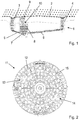
- a channel system 1 is shown in a heavy rainfall.
- Surface water from a road 2 passes through corresponding shafts 3, 4 in the channel system and is fed via channels 5, 6 a main channel 7.
- a dome shaft 8 is formed, which is closed with a watertight manhole cover 9, so that no surface water enters the channel system 1 from there.
- a lid 11 of a manhole cover according to the invention is shown.
- the circular lid has a structured top 12, in the recessed grips 13, 14 are diametrically opposed to each other.
- the lid 11 is further provided with round openings 15 which are arranged on a circular line.
- Fig. 3 the lid 11 is shown in side sectional view, each with a pressure relief device 16 is disposed in the openings 15. Furthermore, ribs 18 formed on an underside 17 of the lid 11 can be seen, which open into a centric, cylindrical wall 19. Locking latches 20 are arranged on the underside of the cover 11, wherein a total of four evenly distributed over the circumference of the lid 11 locking bolt 20 are provided, but in the illustration after Fig. 3 only two locking latch 20a, 20b can be seen. At the outer edge of the lid 11, this has on its underside 17 a circumferential contact surface 21 for abutment against a frame, not shown, of the manhole cover 9.
- Fig. 4 is a detail view too Fig. 3 shown.
- the pressure relief device 16 is arranged, which is designed in the form of a cap 22 which is pressed into the opening 15.
- the cap 22 can be destroyed in the manner of a bursting cap or ejected from the opening 15. This ensures a quick pressure reduction in the shaft.
- the cap 22 has a relatively thick base 23 with conical edges 24, wherein the edges 24 are inclined at the same angle as side edges 25 of the opening 15. Accordingly, between the edges 24 of the cap 22 and the side edges 25 of Opening 15 get a surface contact, which is sufficiently tragwasser- and odor-proof.
- the cap 22 terminates flush with the top 12 of the lid 11.
- the cap 11 On the underside, the cap 11 has a cylindrical wall 26, which has an outwardly projecting escapement 27 in the form of a circumferential bead on its end remote from the base.
- the wall 26 serves to facilitate insertion of the cap 22 in the opening 15 and comes with a lower end of the side edges 25 of the aperture 15 in contact. As a result, it ensures a play-free hold of the cap 22 in the opening 15. In this case, an unauthorized removal of the cap 22 is prevented by the escapement 27.
- the cap 22 is pressed into the opening 15 and thus frictionally and frictionally held tightly in the opening 15, wherein a piercing of the cap 22 from the top 12 to the bottom 17 is prevented by the inclined side edges.
- Fig. 5 an alternative or additional embodiment of the pressure relief device 16 is shown, wherein the cap 22 is formed substantially plate-shaped and rests on a circumferential projection 28 of the lid 11.
- the cap 22 is stepped according to its edge 24 formed.
- a pin 29 Centrally attached to an inner side of the cap 22, a pin 29 which is guided by a arranged on the underside 17 of the lid 11 cage 30.
- the pin has at its free end an adjustable stop 31, wherein between the cage 30 and the stop 31, a spring element 32 is arranged in the form of a helical compression spring.
- the spring element 32 exerts a force in the closing direction on the cap 22 via the pin 29, so it pulls it into the opening 15, so to speak. This ensures a secure, watertight closure of the opening 15 through the cap 22.
- the spring force can be adjusted so that both a traffic-proof attachment and an optimal opening pressure for the valve function is achieved.
- FIG. 5 While in Fig. 5 an embodiment is shown in which only a central opening in the lid 11 and accordingly only a spring-loaded cap 22 is provided, shows Fig. 6 an embodiment with a plurality of openings 15 and pressure relief devices 16.
- the caps 22 have compared to the embodiment according to Fig. 4 a reduced Diameter, but are otherwise designed similar.
- each aperture 15 is associated with a cap 22 and a coaxially arranged cage 30.
- Fig. 7 is the pressure relief device 16, as in the embodiment according to Fig. 6 is used, shown in an enlarged sectional view.
- the plate-shaped cap 22 has on its underside at its base 23 a thickening 33. This is formed from a plastic and provides for an improved sealing and for a simplified attachment of the pin 29 to the cap 22.
- the pin 22 is guided by a arranged on the bottom 17 of the lid 11 cage 30 and has at his End of a designed as a nut stop 31.
- a spring element designed as a helical compression spring is clamped between the stop 31 and the cage 30 and pulls the cap 22 into the opening 15.
- the cap 22 acts as a valve plate of a spring-loaded overload valve.
- Fig. 8 shows a further embodiment of the manhole cover 9 according to the invention, in which the locking bolt 20 are movably connected to the lid 1, that the lid 11 perpendicular to its extension relative to the locking bolt 20 against a force applied by spring elements 32 spring force of his investment in the frame, not shown can remove.
- the lid 11 thus acts as a valve plate of a spring-loadedrichelastrventils.
- the locking bolt 20 take over the function of the cages 30 in the previous embodiments. Accordingly, the pin 29 is guided in each case by a locking bolt 20, wherein in each case a spring element between the pin 29 located on the stop 31 and the locking bolt is clamped.
- the lid 11 is pulled into the frame, not shown, and held accordingly safe.
- the spring force can be adjusted so that both a traffic-proof attachment and an optimal opening pressure for the valve function is achieved.
- the pressure relief device may also be positioned at other locations of the lid. Any number of pressure relief devices may be provided, with a symmetrical arrangement appears advantageous.
- the pressure relief device as a kind of bursting cap or as a spring-loaded overload valve also additional designs are conceivable, for example the use of an elastomeric sealing element. It can be influenced by the choice of the material of the cap, preferably plastic or metal, the holding forces and the sealing effect.
Claims (15)
- Tampon de regard avec un couvercle (11) et avec un cadre, le couvercle (11) étant placé sur le cadre de manière étanche aux eaux superficielles, caractérisé en ce que le tampon de regard (9) comporte un dispositif d'allégement de pression (16) et en ce que le couvercle (11) comporte au moins un évidement (15) dans lequel est agencé le dispositif d'allégement de pression (16).
- Tampon de regard selon la revendication 1, caractérisé en ce que l'évidement (15) est agencé de manière centrée dans le couvercle (11) et/ou en ce que le couvercle (11) comporte plusieurs évidements (15).
- Tampon de regard selon l'une des revendications précédentes, caractérisé en ce que des nervures (18) qui s'étendent en particulier de façon radiale sont réalisées au niveau d'un côté inférieur (17) du couvercle (11).
- Tampon de regard selon l'une des revendications précédentes, caractérisé en ce qu'une paroi (19) entoure l'évidement (15) réalisé au centre.
- Tampon de regard selon l'une des revendications précédentes, caractérisé en ce que le dispositif d'allégement de pression (16) est conçu comme un couronnement (22) dont le contour est adapté à la forme de l'évidement (15) et qui peut être placé de manière étanche dans l'évidement (15).
- Tampon de regard selon la revendication 6, caractérisé en ce que l'évidement (15) présente des bords latéraux (25) inclinés, le couronnement (22) étant réalisé, de manière correspondante, conique au niveau de ses bords (24).
- Tampon de regard selon la revendication 5 ou 6, caractérisé en ce que le couronnement (22) présente une surface de base (23) du côté intérieur de laquelle part une paroi (26) périphérique et en particulier cylindrique.
- Tampon de regard selon la revendication 7, caractérisé en ce qu'au moins un dispositif d'arrêt (27) dépassant vers l'extérieur est agencé au niveau de la paroi (26), lequel dispositif d'arrêt est conçu en particulier comme un bourrelet périphérique.
- Tampon de regard selon l'une des revendications 5 à 8, caractérisé en ce que le couronnement (22) comporte une matière plastique.
- Tampon de regard selon l'une des revendications 5 à 9, caractérisé en ce que le couronnement (22) est conçu comme une fermeture contrainte par ressort pour l'évidement (15).
- Tampon de regard selon la revendication 10, caractérisé en ce que le couronnement (22) comporte au niveau d'un côté intérieur une broche (29) qui passe à travers une cage (30) agencée au niveau du côté inférieur (17) du couvercle (11), la broche (29) étant agencée en particulier centrée au niveau du couronnement (22).
- Tampon de regard selon la revendication 11, caractérisé en ce que la broche (29) comporte une butée (31) réglable en particulier par l'intermédiaire d'un couple de filetages, un élément formant ressort (32) étant contraint entre la butée (31) et la cage (30).
- Tampon de regard selon l'une des revendications précédentes, caractérisé en ce que des verrous (20) destinés à la fixation au cadre sont agencés au niveau du côté inférieur (17) du couvercle (11).
- Tampon de regard selon l'une des revendications précédentes, caractérisé en ce que le couvercle (11) est assemblé de manière mobile aux verrous (20), les verrous (20) étant contraints en direction du couvercle (11) par l'intermédiaire d'éléments formant ressort (32).
- Tampon de regard selon la revendication 14, caractérisé en ce que des broches (29) assemblées de manière fixe au couvercle (11) passent par les verrous (20), les broches (29) comportant une butée (31) en particulier réglable et l'élément formant ressort (32) étant contraint entre le verrou (20) et la butée (31).
Priority Applications (1)
| Application Number | Priority Date | Filing Date | Title |
|---|---|---|---|
| PL14185446T PL2857589T3 (pl) | 2013-09-20 | 2014-09-18 | Układy zabezpieczające przed wysadzeniem pokryw studzienek |
Applications Claiming Priority (1)
| Application Number | Priority Date | Filing Date | Title |
|---|---|---|---|
| DE102013110452.5A DE102013110452A1 (de) | 2013-09-20 | 2013-09-20 | Schachtabdeckung |
Publications (2)
| Publication Number | Publication Date |
|---|---|
| EP2857589A1 EP2857589A1 (fr) | 2015-04-08 |
| EP2857589B1 true EP2857589B1 (fr) | 2017-11-29 |
Family
ID=51589123
Family Applications (1)
| Application Number | Title | Priority Date | Filing Date |
|---|---|---|---|
| EP14185446.3A Active EP2857589B1 (fr) | 2013-09-20 | 2014-09-18 | Systèmes de protection contre l'éclatement pour regards de chaussée |
Country Status (3)
| Country | Link |
|---|---|
| EP (1) | EP2857589B1 (fr) |
| DE (1) | DE102013110452A1 (fr) |
| PL (1) | PL2857589T3 (fr) |
Families Citing this family (4)
| Publication number | Priority date | Publication date | Assignee | Title |
|---|---|---|---|---|
| CN111456095A (zh) * | 2020-04-10 | 2020-07-28 | 嘉兴恒力建材科技有限公司 | 一种智能泄压抑爆防井盖飞起的安全井盖 |
| CN113235665B (zh) * | 2021-06-08 | 2022-05-13 | 辽宁工程技术大学 | 一种可用于市政紧急排水的井盖结构 |
| CN113513046B (zh) * | 2021-07-06 | 2023-06-09 | 广西北海精一电力器材有限责任公司 | 一种环氧树脂复合盖板及制作方法 |
| CN117090246A (zh) * | 2023-10-20 | 2023-11-21 | 山东鲁润塑业股份有限公司 | 一种可自锁的分体式高分子井盖 |
Family Cites Families (5)
| Publication number | Priority date | Publication date | Assignee | Title |
|---|---|---|---|---|
| US1071577A (en) * | 1913-03-19 | 1913-08-26 | Charles E Rego | Device for preventing blowing off of manhole-covers. |
| US2025839A (en) * | 1932-05-12 | 1935-12-31 | Cons Gas Company Of New York | Manhole closure |
| DE3812077A1 (de) * | 1988-04-12 | 1988-12-08 | Eichelmann Horst | Doppelwandiger deckel mit betonfuellung |
| WO2007146256A2 (fr) * | 2006-06-12 | 2007-12-21 | Stadler David M | Verrou de sécurité pour couvercle de trou d'homme avec libération de pression commandée |
| GB2504452B (en) * | 2012-05-30 | 2017-09-06 | Spencer Price Paul | Improvements in and relating to manhole covers |
-
2013
- 2013-09-20 DE DE102013110452.5A patent/DE102013110452A1/de not_active Withdrawn
-
2014
- 2014-09-18 PL PL14185446T patent/PL2857589T3/pl unknown
- 2014-09-18 EP EP14185446.3A patent/EP2857589B1/fr active Active
Non-Patent Citations (1)
| Title |
|---|
| None * |
Also Published As
| Publication number | Publication date |
|---|---|
| DE102013110452A1 (de) | 2015-03-26 |
| EP2857589A1 (fr) | 2015-04-08 |
| PL2857589T3 (pl) | 2018-05-30 |
Similar Documents
| Publication | Publication Date | Title |
|---|---|---|
| EP2873894B1 (fr) | Bouchon de fermeture | |
| DE102007026543B4 (de) | Entwässerungsstopfen | |
| EP2857589B1 (fr) | Systèmes de protection contre l'éclatement pour regards de chaussée | |
| DE102007008066A1 (de) | Fitting und Verbindungsanordnung mit einem Fitting | |
| EP1623749B1 (fr) | Agencement d'un filtre à huile | |
| DE102010060771A1 (de) | Befestigungselement | |
| EP3285902A1 (fr) | Élément filtrant équipé d'un élément d'enlèvement | |
| EP2796646B1 (fr) | Cadenas | |
| DE102017011081A1 (de) | Filtersystem und Filterelement | |
| DE102009054628A1 (de) | Teleskopstütze für den Baubereich | |
| EP1984228A1 (fr) | Dispositif pour dégager une ouverture dans un élément de boîtier d'un mécanisme de direction | |
| DE2910317A1 (de) | Hydropneumatischer einrohr-schwingungsdaempfer | |
| EP1440633B1 (fr) | Colonne télescopique | |
| DE202009003184U1 (de) | Dichtungsvorrichtung zum Abdichten eines Durchbruchs | |
| EP3450674A1 (fr) | Store roulant ainsi que protection de levage correspondante | |
| DE202006006201U1 (de) | Vorrichtung zum Verhindern des Ausspritzens von Kraftstoff aus einem Kraftstofftank bei offenem Tankstutzen | |
| DE102017212009A1 (de) | Zugentlastungstülle | |
| EP3689786A1 (fr) | Dispositif de réception de déchets | |
| DE102009043734A1 (de) | Rohrstopfen | |
| EP3763880B1 (fr) | Dispositif, de préférence d'encastrement affleurant la surface de la chaussée | |
| DE3232178A1 (de) | Verschlussdeckel | |
| DE102012105311A1 (de) | Bodenablauf | |
| DE19949697B4 (de) | Vorrichtung zum Verschliessen von Rohrenden | |
| EP0989058B1 (fr) | Soupape de purge à fermeture automatique pour un réservoir d'hélicoptère | |
| EP4306727A1 (fr) | Tringles de bouche d'incendie, bouche d'incendie, ainsi que procédé de réglage de la longueur des tringles de bouche d'incendie |
Legal Events
| Date | Code | Title | Description |
|---|---|---|---|
| PUAI | Public reference made under article 153(3) epc to a published international application that has entered the european phase |
Free format text: ORIGINAL CODE: 0009012 |
|
| 17P | Request for examination filed |
Effective date: 20140918 |
|
| AK | Designated contracting states |
Kind code of ref document: A1 Designated state(s): AL AT BE BG CH CY CZ DE DK EE ES FI FR GB GR HR HU IE IS IT LI LT LU LV MC MK MT NL NO PL PT RO RS SE SI SK SM TR |
|
| AX | Request for extension of the european patent |
Extension state: BA ME |
|
| R17P | Request for examination filed (corrected) |
Effective date: 20150727 |
|
| RBV | Designated contracting states (corrected) |
Designated state(s): AL AT BE BG CH CY CZ DE DK EE ES FI FR GB GR HR HU IE IS IT LI LT LU LV MC MK MT NL NO PL PT RO RS SE SI SK SM TR |
|
| GRAP | Despatch of communication of intention to grant a patent |
Free format text: ORIGINAL CODE: EPIDOSNIGR1 |
|
| INTG | Intention to grant announced |
Effective date: 20170622 |
|
| GRAS | Grant fee paid |
Free format text: ORIGINAL CODE: EPIDOSNIGR3 |
|
| GRAA | (expected) grant |
Free format text: ORIGINAL CODE: 0009210 |
|
| AK | Designated contracting states |
Kind code of ref document: B1 Designated state(s): AL AT BE BG CH CY CZ DE DK EE ES FI FR GB GR HR HU IE IS IT LI LT LU LV MC MK MT NL NO PL PT RO RS SE SI SK SM TR |
|
| REG | Reference to a national code |
Ref country code: CH Ref legal event code: EP |
|
| REG | Reference to a national code |
Ref country code: AT Ref legal event code: REF Ref document number: 950525 Country of ref document: AT Kind code of ref document: T Effective date: 20171215 |
|
| REG | Reference to a national code |
Ref country code: IE Ref legal event code: FG4D Free format text: LANGUAGE OF EP DOCUMENT: GERMAN |
|
| REG | Reference to a national code |
Ref country code: DE Ref legal event code: R096 Ref document number: 502014006387 Country of ref document: DE |
|
| REG | Reference to a national code |
Ref country code: NL Ref legal event code: FP |
|
| REG | Reference to a national code |
Ref country code: LT Ref legal event code: MG4D |
|
| PG25 | Lapsed in a contracting state [announced via postgrant information from national office to epo] |
Ref country code: SE Free format text: LAPSE BECAUSE OF FAILURE TO SUBMIT A TRANSLATION OF THE DESCRIPTION OR TO PAY THE FEE WITHIN THE PRESCRIBED TIME-LIMIT Effective date: 20171129 Ref country code: NO Free format text: LAPSE BECAUSE OF FAILURE TO SUBMIT A TRANSLATION OF THE DESCRIPTION OR TO PAY THE FEE WITHIN THE PRESCRIBED TIME-LIMIT Effective date: 20180228 Ref country code: LT Free format text: LAPSE BECAUSE OF FAILURE TO SUBMIT A TRANSLATION OF THE DESCRIPTION OR TO PAY THE FEE WITHIN THE PRESCRIBED TIME-LIMIT Effective date: 20171129 Ref country code: FI Free format text: LAPSE BECAUSE OF FAILURE TO SUBMIT A TRANSLATION OF THE DESCRIPTION OR TO PAY THE FEE WITHIN THE PRESCRIBED TIME-LIMIT Effective date: 20171129 Ref country code: ES Free format text: LAPSE BECAUSE OF FAILURE TO SUBMIT A TRANSLATION OF THE DESCRIPTION OR TO PAY THE FEE WITHIN THE PRESCRIBED TIME-LIMIT Effective date: 20171129 |
|
| PG25 | Lapsed in a contracting state [announced via postgrant information from national office to epo] |
Ref country code: RS Free format text: LAPSE BECAUSE OF FAILURE TO SUBMIT A TRANSLATION OF THE DESCRIPTION OR TO PAY THE FEE WITHIN THE PRESCRIBED TIME-LIMIT Effective date: 20171129 Ref country code: GR Free format text: LAPSE BECAUSE OF FAILURE TO SUBMIT A TRANSLATION OF THE DESCRIPTION OR TO PAY THE FEE WITHIN THE PRESCRIBED TIME-LIMIT Effective date: 20180301 Ref country code: HR Free format text: LAPSE BECAUSE OF FAILURE TO SUBMIT A TRANSLATION OF THE DESCRIPTION OR TO PAY THE FEE WITHIN THE PRESCRIBED TIME-LIMIT Effective date: 20171129 Ref country code: BG Free format text: LAPSE BECAUSE OF FAILURE TO SUBMIT A TRANSLATION OF THE DESCRIPTION OR TO PAY THE FEE WITHIN THE PRESCRIBED TIME-LIMIT Effective date: 20180228 Ref country code: LV Free format text: LAPSE BECAUSE OF FAILURE TO SUBMIT A TRANSLATION OF THE DESCRIPTION OR TO PAY THE FEE WITHIN THE PRESCRIBED TIME-LIMIT Effective date: 20171129 |
|
| PG25 | Lapsed in a contracting state [announced via postgrant information from national office to epo] |
Ref country code: EE Free format text: LAPSE BECAUSE OF FAILURE TO SUBMIT A TRANSLATION OF THE DESCRIPTION OR TO PAY THE FEE WITHIN THE PRESCRIBED TIME-LIMIT Effective date: 20171129 Ref country code: CY Free format text: LAPSE BECAUSE OF FAILURE TO SUBMIT A TRANSLATION OF THE DESCRIPTION OR TO PAY THE FEE WITHIN THE PRESCRIBED TIME-LIMIT Effective date: 20171129 Ref country code: DK Free format text: LAPSE BECAUSE OF FAILURE TO SUBMIT A TRANSLATION OF THE DESCRIPTION OR TO PAY THE FEE WITHIN THE PRESCRIBED TIME-LIMIT Effective date: 20171129 Ref country code: CZ Free format text: LAPSE BECAUSE OF FAILURE TO SUBMIT A TRANSLATION OF THE DESCRIPTION OR TO PAY THE FEE WITHIN THE PRESCRIBED TIME-LIMIT Effective date: 20171129 Ref country code: SK Free format text: LAPSE BECAUSE OF FAILURE TO SUBMIT A TRANSLATION OF THE DESCRIPTION OR TO PAY THE FEE WITHIN THE PRESCRIBED TIME-LIMIT Effective date: 20171129 |
|
| REG | Reference to a national code |
Ref country code: DE Ref legal event code: R097 Ref document number: 502014006387 Country of ref document: DE |
|
| PG25 | Lapsed in a contracting state [announced via postgrant information from national office to epo] |
Ref country code: SM Free format text: LAPSE BECAUSE OF FAILURE TO SUBMIT A TRANSLATION OF THE DESCRIPTION OR TO PAY THE FEE WITHIN THE PRESCRIBED TIME-LIMIT Effective date: 20171129 Ref country code: RO Free format text: LAPSE BECAUSE OF FAILURE TO SUBMIT A TRANSLATION OF THE DESCRIPTION OR TO PAY THE FEE WITHIN THE PRESCRIBED TIME-LIMIT Effective date: 20171129 Ref country code: IT Free format text: LAPSE BECAUSE OF FAILURE TO SUBMIT A TRANSLATION OF THE DESCRIPTION OR TO PAY THE FEE WITHIN THE PRESCRIBED TIME-LIMIT Effective date: 20171129 |
|
| PG25 | Lapsed in a contracting state [announced via postgrant information from national office to epo] |
Ref country code: MT Free format text: LAPSE BECAUSE OF FAILURE TO SUBMIT A TRANSLATION OF THE DESCRIPTION OR TO PAY THE FEE WITHIN THE PRESCRIBED TIME-LIMIT Effective date: 20171129 |
|
| PLBE | No opposition filed within time limit |
Free format text: ORIGINAL CODE: 0009261 |
|
| STAA | Information on the status of an ep patent application or granted ep patent |
Free format text: STATUS: NO OPPOSITION FILED WITHIN TIME LIMIT |
|
| 26N | No opposition filed |
Effective date: 20180830 |
|
| PG25 | Lapsed in a contracting state [announced via postgrant information from national office to epo] |
Ref country code: SI Free format text: LAPSE BECAUSE OF FAILURE TO SUBMIT A TRANSLATION OF THE DESCRIPTION OR TO PAY THE FEE WITHIN THE PRESCRIBED TIME-LIMIT Effective date: 20171129 |
|
| PG25 | Lapsed in a contracting state [announced via postgrant information from national office to epo] |
Ref country code: MC Free format text: LAPSE BECAUSE OF FAILURE TO SUBMIT A TRANSLATION OF THE DESCRIPTION OR TO PAY THE FEE WITHIN THE PRESCRIBED TIME-LIMIT Effective date: 20171129 |
|
| GBPC | Gb: european patent ceased through non-payment of renewal fee |
Effective date: 20180918 |
|
| REG | Reference to a national code |
Ref country code: BE Ref legal event code: MM Effective date: 20180930 |
|
| REG | Reference to a national code |
Ref country code: IE Ref legal event code: MM4A |
|
| PG25 | Lapsed in a contracting state [announced via postgrant information from national office to epo] |
Ref country code: IE Free format text: LAPSE BECAUSE OF NON-PAYMENT OF DUE FEES Effective date: 20180918 |
|
| PG25 | Lapsed in a contracting state [announced via postgrant information from national office to epo] |
Ref country code: FR Free format text: LAPSE BECAUSE OF NON-PAYMENT OF DUE FEES Effective date: 20180930 Ref country code: BE Free format text: LAPSE BECAUSE OF NON-PAYMENT OF DUE FEES Effective date: 20180930 |
|
| PG25 | Lapsed in a contracting state [announced via postgrant information from national office to epo] |
Ref country code: GB Free format text: LAPSE BECAUSE OF NON-PAYMENT OF DUE FEES Effective date: 20180918 |
|
| PG25 | Lapsed in a contracting state [announced via postgrant information from national office to epo] |
Ref country code: TR Free format text: LAPSE BECAUSE OF FAILURE TO SUBMIT A TRANSLATION OF THE DESCRIPTION OR TO PAY THE FEE WITHIN THE PRESCRIBED TIME-LIMIT Effective date: 20171129 |
|
| PG25 | Lapsed in a contracting state [announced via postgrant information from national office to epo] |
Ref country code: PT Free format text: LAPSE BECAUSE OF FAILURE TO SUBMIT A TRANSLATION OF THE DESCRIPTION OR TO PAY THE FEE WITHIN THE PRESCRIBED TIME-LIMIT Effective date: 20171129 Ref country code: HU Free format text: LAPSE BECAUSE OF FAILURE TO SUBMIT A TRANSLATION OF THE DESCRIPTION OR TO PAY THE FEE WITHIN THE PRESCRIBED TIME-LIMIT; INVALID AB INITIO Effective date: 20140918 |
|
| PG25 | Lapsed in a contracting state [announced via postgrant information from national office to epo] |
Ref country code: MK Free format text: LAPSE BECAUSE OF NON-PAYMENT OF DUE FEES Effective date: 20171129 |
|
| PG25 | Lapsed in a contracting state [announced via postgrant information from national office to epo] |
Ref country code: AL Free format text: LAPSE BECAUSE OF FAILURE TO SUBMIT A TRANSLATION OF THE DESCRIPTION OR TO PAY THE FEE WITHIN THE PRESCRIBED TIME-LIMIT Effective date: 20171129 Ref country code: IS Free format text: LAPSE BECAUSE OF FAILURE TO SUBMIT A TRANSLATION OF THE DESCRIPTION OR TO PAY THE FEE WITHIN THE PRESCRIBED TIME-LIMIT Effective date: 20180329 |
|
| PGFP | Annual fee paid to national office [announced via postgrant information from national office to epo] |
Ref country code: NL Payment date: 20230920 Year of fee payment: 10 Ref country code: LU Payment date: 20230921 Year of fee payment: 10 Ref country code: AT Payment date: 20230921 Year of fee payment: 10 |
|
| PGFP | Annual fee paid to national office [announced via postgrant information from national office to epo] |
Ref country code: PL Payment date: 20230908 Year of fee payment: 10 Ref country code: DE Payment date: 20230930 Year of fee payment: 10 |
|
| PGFP | Annual fee paid to national office [announced via postgrant information from national office to epo] |
Ref country code: CH Payment date: 20231001 Year of fee payment: 10 |