EP2857578B1 - Appareil de repassage comportant une base generatrice de vapeur et un fer a repasser reliés entre eux par un conduit de vapeur - Google Patents
Appareil de repassage comportant une base generatrice de vapeur et un fer a repasser reliés entre eux par un conduit de vapeur Download PDFInfo
- Publication number
- EP2857578B1 EP2857578B1 EP14186968.5A EP14186968A EP2857578B1 EP 2857578 B1 EP2857578 B1 EP 2857578B1 EP 14186968 A EP14186968 A EP 14186968A EP 2857578 B1 EP2857578 B1 EP 2857578B1
- Authority
- EP
- European Patent Office
- Prior art keywords
- steam
- appliance according
- ironing appliance
- duct
- heating
- Prior art date
- Legal status (The legal status is an assumption and is not a legal conclusion. Google has not performed a legal analysis and makes no representation as to the accuracy of the status listed.)
- Active
Links
- XEEYBQQBJWHFJM-UHFFFAOYSA-N Iron Chemical group [Fe] XEEYBQQBJWHFJM-UHFFFAOYSA-N 0.000 title claims description 60
- 238000010409 ironing Methods 0.000 title claims description 38
- 229910052742 iron Inorganic materials 0.000 title claims description 29
- 238000010438 heat treatment Methods 0.000 claims description 69
- 238000009792 diffusion process Methods 0.000 claims description 25
- 238000001035 drying Methods 0.000 claims description 16
- 238000009954 braiding Methods 0.000 claims description 9
- 229920002943 EPDM rubber Polymers 0.000 claims description 7
- 230000003014 reinforcing effect Effects 0.000 claims description 7
- 229920003235 aromatic polyamide Polymers 0.000 claims description 6
- 229920001343 polytetrafluoroethylene Polymers 0.000 claims description 5
- 239000004810 polytetrafluoroethylene Substances 0.000 claims description 5
- 239000004760 aramid Substances 0.000 claims description 4
- 239000004744 fabric Substances 0.000 claims description 4
- 229920001296 polysiloxane Polymers 0.000 claims description 4
- 229910001220 stainless steel Inorganic materials 0.000 claims description 4
- 239000003365 glass fiber Substances 0.000 claims description 3
- 239000000203 mixture Substances 0.000 claims description 3
- 239000013536 elastomeric material Substances 0.000 claims 1
- 238000009499 grossing Methods 0.000 claims 1
- 239000000463 material Substances 0.000 description 5
- 239000000835 fiber Substances 0.000 description 4
- XLYOFNOQVPJJNP-UHFFFAOYSA-N water Substances O XLYOFNOQVPJJNP-UHFFFAOYSA-N 0.000 description 4
- 239000011324 bead Substances 0.000 description 3
- 238000009833 condensation Methods 0.000 description 3
- 230000005494 condensation Effects 0.000 description 3
- 208000031968 Cadaver Diseases 0.000 description 2
- -1 Polytetrafluoroethylene Polymers 0.000 description 2
- 229910052782 aluminium Inorganic materials 0.000 description 2
- XAGFODPZIPBFFR-UHFFFAOYSA-N aluminium Chemical compound [Al] XAGFODPZIPBFFR-UHFFFAOYSA-N 0.000 description 2
- 238000001816 cooling Methods 0.000 description 2
- 239000004033 plastic Substances 0.000 description 2
- 230000002787 reinforcement Effects 0.000 description 2
- 239000010935 stainless steel Substances 0.000 description 2
- 229920000271 Kevlar® Polymers 0.000 description 1
- 229920000784 Nomex Polymers 0.000 description 1
- 229920000561 Twaron Polymers 0.000 description 1
- 229920006231 aramid fiber Polymers 0.000 description 1
- 238000009835 boiling Methods 0.000 description 1
- 239000004020 conductor Substances 0.000 description 1
- 238000010276 construction Methods 0.000 description 1
- 210000003298 dental enamel Anatomy 0.000 description 1
- 229920001971 elastomer Polymers 0.000 description 1
- 239000000806 elastomer Substances 0.000 description 1
- 238000005485 electric heating Methods 0.000 description 1
- 230000005611 electricity Effects 0.000 description 1
- 238000001704 evaporation Methods 0.000 description 1
- 230000008020 evaporation Effects 0.000 description 1
- 239000011810 insulating material Substances 0.000 description 1
- 238000009413 insulation Methods 0.000 description 1
- 238000004519 manufacturing process Methods 0.000 description 1
- 229910052751 metal Inorganic materials 0.000 description 1
- 239000002184 metal Substances 0.000 description 1
- 238000012986 modification Methods 0.000 description 1
- 230000004048 modification Effects 0.000 description 1
- 238000000465 moulding Methods 0.000 description 1
- 239000004763 nomex Substances 0.000 description 1
- 238000013021 overheating Methods 0.000 description 1
- 230000002093 peripheral effect Effects 0.000 description 1
- 238000003825 pressing Methods 0.000 description 1
- 230000007420 reactivation Effects 0.000 description 1
- 230000001105 regulatory effect Effects 0.000 description 1
- 238000010186 staining Methods 0.000 description 1
- 238000006467 substitution reaction Methods 0.000 description 1
Images

Classifications
-
- D—TEXTILES; PAPER
- D06—TREATMENT OF TEXTILES OR THE LIKE; LAUNDERING; FLEXIBLE MATERIALS NOT OTHERWISE PROVIDED FOR
- D06F—LAUNDERING, DRYING, IRONING, PRESSING OR FOLDING TEXTILE ARTICLES
- D06F75/00—Hand irons
- D06F75/08—Hand irons internally heated by electricity
- D06F75/10—Hand irons internally heated by electricity with means for supplying steam to the article being ironed
- D06F75/12—Hand irons internally heated by electricity with means for supplying steam to the article being ironed the steam being produced from water supplied to the iron from an external source
-
- D—TEXTILES; PAPER
- D06—TREATMENT OF TEXTILES OR THE LIKE; LAUNDERING; FLEXIBLE MATERIALS NOT OTHERWISE PROVIDED FOR
- D06F—LAUNDERING, DRYING, IRONING, PRESSING OR FOLDING TEXTILE ARTICLES
- D06F75/00—Hand irons
- D06F75/08—Hand irons internally heated by electricity
- D06F75/10—Hand irons internally heated by electricity with means for supplying steam to the article being ironed
Definitions
- the present invention relates to an ironing apparatus comprising a steam generating base and an iron connected together by a conduit for the transport of steam, the iron comprising an ironing sole comprising at least one zone of ironing.
- humidifying the laundry provided with steam outlet holes and at least one drying zone without steam outlet holes, the steam outlet holes being fed by a diffusion chamber arranged in a non-heating body covering the sole at the level of the humidifying zone of the laundry, the drying zone being in thermal contact with a heating body.
- an ironing apparatus comprising a steam generating base and an iron connected together by a conduit for the transport of steam, the iron comprising a sole having a front portion provided with exit holes of steam and a rear portion without steam outlet holes, the steam outlet holes of the sole being supplied by a diffusion chamber arranged in a non-heating body covering the front portion of the sole, the rear portion being in thermal contact of a heating body.
- An ironing apparatus equipped with such an iron has the advantage of having a sole provided with a zone of humidification of the laundry, by emission of steam, distinct from a hot zone of drying of the linen, the sole being without heating element in the vicinity of the humidifying zone of the laundry, to obtain a better condensation of the steam on the laundry and greater ironing efficiency.
- the steam is passed through a distribution circuit in the heating body surmounting the rear part of the soleplate to ensure the evaporation of the condensates forming in the connecting pipe.
- the apparatus can be caused to spew condensate through the outlet holes of the sole.
- the steam reaches the outlet holes of the sole with a temperature too high to ensure good condensation of the vapor as soon as it comes into contact with the fabric.
- an object of the present invention is to provide an ironing apparatus that overcomes these disadvantages.
- Another object of the present invention is to provide an apparatus that is simple and economical to implement.
- the subject of the invention is an ironing apparatus comprising a steam generating base and an iron connected together by a steam duct, the iron comprising an ironing soleplate comprising at least one zone of ironing.
- humification of the laundry provided with steam outlet holes and at least one drying zone without steam outlet holes, the steam outlet holes being fed by a diffusion chamber arranged in a non-heating body covering the sole at the level of the humification zone of the laundry, the drying zone being in thermal contact with a heating body, characterized in that the steam duct comprises a heating element, the diffusion chamber being supplied directly by the steam coming from the duct, without cross the heating body.
- Such a characteristic makes it possible to obtain a stream of vapor with an optimized temperature and humidity level to ensure good humidification of the laundry, by reducing the risk of staining the laundry with steam condensates.
- the presence of the heating element on the steam duct makes it possible to maintain the steam in the steam duct at a sufficiently high temperature so that it does not occur or very few condensates.
- the absence of a heating element on the body comprising the vapor diffusion chamber makes it possible at the same time to simplify the construction of the iron and to not overheat the steam in order to obtain a wet vapor.
- the power and the power supply of the heating element are adapted so that the temperature of the steam at the outlet of the steam duct is between 100 ° C. and 110 ° C.
- the diffusion chamber is adapted to lower the temperature of the vapor coming from the steam duct and to bring it to a temperature of about 100 ° C. at the level of the steam outlet holes. of the sole.
- the heating element of the steam duct has a power of between 100W and 400W.
- the heating body comprises a screen-printed flat heating element.
- Such a heating element has the advantage of having a low thermal inertia and thus makes it possible to obtain a rapid change in the temperature of the sole, especially in the cooling phases.
- the surface of the humification zone of the soleplate, covered by the diffusion chamber represents between 30% and 50% of the total surface of the soleplate.
- Such a characteristic makes it possible to offer an optimum surface ratio between the humidification zone and the drying zone of the laundry.
- the steam duct is made of elastomeric EPDM material (ethylene-propylene-diene monomer) non-conductive electricity or silicone.
- Such materials have the advantage of having a good resistance to steam and good resistance to pressure.
- the heating element comprises at least one heating wire which is braided on the steam duct, said heating wire providing only a partial coverage of the steam duct.
- the heating wire is constituted by a stainless steel wire of diameter less than 1 mm, advantageously coated with PTFE (Polytetrafluoroethylene).
- PTFE Polytetrafluoroethylene
- the steam duct comprises reinforcing threads, advantageously made of para-aramid fiber, which are braided on the steam duct, the reinforcing threads ensuring only a partial cover of the duct. of steam.
- the steam duct comprises an external braiding covering the entire steam duct, the heating wire and any reinforcing son.
- the external braiding comprises a mixture of meta-aramid fibers and glass fibers.
- the humification zone of the laundry is formed in a front portion of the sole and the drying zone is formed in a rear portion of the sole.
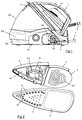
- the figure 1 represents an ironing apparatus comprising a base 100 generating steam and an iron 1 interconnected by a connecting bead 2, the iron 1 typically comprising a sole 3 ironing, preferably made of stainless steel or in a sheet aluminum covered with enamel, surmounted by a plastic case conventionally incorporating a handle.
- the base 100 comprises an inclined plane on which the iron 1 can come to rest during the inactive ironing phases and contains, in a manner known per se, a tank 101 for the production of steam under a pressure of the order of 4 to 6 bars.
- the tank 101 is supplied with water from a tank 102 by means of a pump 103 and comprises a steam outlet orifice equipped with a solenoid valve 104 controlled by a trigger 10 opened under the iron handle ironing 1, the solenoid valve 104 being connected to a steam duct 4 integrated in the connecting cord 2.
- the base 100 is connected to the domestic electrical network by an electric wire 105 which allows both the power supply of the heating means of the tank 101 and the power supply of the iron 1 by means of several electrical wires, not shown. in the figures, integrated in the connecting cord 2.
- the sole 3 of the iron has a front portion having a humification zone 30 of the laundry, provided with steam outlet holes 21, surmounted by a non-heating body 5 and has a rear portion comprising a drying zone 32 , lacking steam outlet holes, surmounted by a heating body 6, the humidifying zone 30 of the laundry preferably representing between 30 and 50% of the total surface of sole 3.
- the heating body 6 is advantageously constituted by a metal plate comprising a screen-printed flat heating element 60 with a power of between 200 W and 500 W, which comes into contact with the rear part of the drying zone 32 of the sole 3, this screen-printed flat heating element 60 being electrically powered by an electronic card comprising a thermostat allowing regulation of the temperature of the drying zone 32 of the sole 3 around a set temperature, advantageously adjustable by the user, between 115 ° C and 200 ° C.
- the non-heating body, covering the humidification zone 30 of the soleplate, is constituted by a cover 5 defining a vapor diffusion chamber 50 above the steam outlet holes 31 of the soleplate 3, the cover 5 advantageously being made by molding in a plastic material or in an aluminum foundry.
- the vapor diffusion chamber 50 is constituted by a cavity whose underside is delimited by the front portion of the sole 3 and whose upper and peripheral walls are delimited by the cover 5, the cover 5 having projecting walls extending inside the diffusion chamber 50 to form a circular diffusion channel 51 provided with lateral slots 51A ensuring a homogeneous distribution of the vapor above the front part of the sole 3.
- the steam diffusion chamber 50 is supplied with steam by an inlet orifice 52 formed on the lid 5, the inlet orifice 52 opening into the diffusion channel 51 and being connected directly to the steam duct 4 integrated in the the connecting cord 2 connecting the iron 1 to the steam generating base 100.
- the steam duct 4 comprises a heating element 40 making it possible to limit the cooling of the steam contained in the steam duct 4 and to prevent the appearance of condensates.
- the steam duct 4 is advantageously made of a material elastomer EPDM type (ethylene-propylene-diene monomer), preferably electrically non-conductive, and the heating element is constituted by one or more electric heating son 40 which are braided on the steam duct 4, as shown schematically on the figure 5 .
- EPDM ethylene-propylene-diene monomer
- the heating son 40 consist of stainless steel son with a diameter of less than 1 mm, coated with PTFE (Polytetrafluoroethylene), having an electrical resistance of the order of 13 ohm / m.
- the heating son can be powered with a 220V AC voltage by an electronic card carried by the steam generating base 100, the electrical power of the heating son 40 can be regulated by a thermostat or be carried out continuously or periodically, with an alternation of supply phase and cut-off phases.
- the total power released by the heating son 40 equipping the steam duct 4 is advantageously between 100W and 400W.
- a thermal fuse is preferably affixed to the steam duct 4 to cut the supply current of the heating wires 40 when the temperature of the steam duct 4 exceeds a predetermined threshold, for example of the order of 130 ° C, in order to avoid overheating during a possible failure of the heating wire supply system 40.
- the resistance of the electrical heating wires 40 to the steam duct is advantageously reinforced by a braiding of reinforcing threads 41 which intersect the heating threads 40 partially covering them, the reinforcement thread 41 being preferably constituted by synthetic threads of para- aramid, such as son made from Twaron® fibers marketed by the company Teijin or Kevlar® fibers marketed by the company Du Pont de Nemours.
- para- aramid such as son made from Twaron® fibers marketed by the company Teijin or Kevlar® fibers marketed by the company Du Pont de Nemours.
- the whole of the steam duct 4, heating threads 40 and reinforcement threads 41 thus produced is covered with an external braiding 42 illustrated on FIG. figure 6 whose function is to thermally protect and insulate heating wires 40 from the outside, the external braiding 42 being preferably constituted by a mixture of synthetic meta-aramid yarns and glass fibers covering the whole of the bead 4.
- the synthetic meta-aramid yarns are made from from Nomex® fibers marketed by the company Du Pont de Nemours.
- the tank 101 is heated by its heating means so that the water it contains is brought to boiling, the heating son 40 of the vapor cord 4 being electrically powered as soon as it is put into operation.
- voltage of the apparatus so that the interior of the steam duct 4 is brought to a temperature of at least 100 ° C and preferably at a temperature between 100 ° C and 110 ° C.
- a light indicates to the user that the device is ready for use and the user can perform a steam ironing session by pressing the trigger 10 of the iron to iron 1 to open the solenoid valve 104 and release the steam through the steam duct 4.
- the steam is then transmitted to the iron 1 by passing through the steam duct 4 heated to a temperature greater than or equal to 100 ° C, so that the steam reaches the iron 1 without having been cooled sufficiently to allow the appearance of condensate.
- the steam contained in the steam duct 4 is maintained at a temperature above 100 ° C. even during the ironing phases during which the steam remains stagnant in the steam duct 4, that is to say when user does not pull the trigger 10.
- the steam When the steam reaches the iron 1, it enters directly into the steam diffusion chamber 50 through the inlet orifice 52 formed in the cover 5 covering the humidification zone 30 of the sole 3.
- the passage of vapor flow in the diffusion chamber 50 is accompanied by a decrease in the temperature of the steam, due to the absence of heating element on the lid 5, the temperature of the vapor then falling to to reach a temperature of the order of 100 ° C at the steam outlet holes 31 of the sole, such a lowering of the steam temperature resulting in increasing the moisture content of the steam by increasing the number of small water droplets, less than 10 ⁇ m in diameter, contained in the vapor stream.
- the diffusion of this wet vapor flow makes it possible to guarantee very good ironing performance, the humification zone 30 of the soleplate, covered by the diffusion chamber 50, having the advantage of being heated only by heat conduction. the heating rear portion through the thickness of the sole 3 so that the sole 3 has a low temperature at the steam outlet holes 31, preferably less than 110 ° C, which contributes to an excellent condensation of steam in the ironing board.
- the ironing apparatus thus produced thus has a sole 3 provided with an unheated front part provided with steam outlet holes 31 which makes it possible to obtain an excellent moistening of the laundry while the rear part 32 of the soleplate, which is heated and deprived of steam outlet holes, allows to quickly evaporate all the moisture contained in the laundry when moving the iron 1 forward.
- a screen-printed flat heating element 60 for heating the heating zone of the soleplate 3 makes it possible to obtain a very large reactivation of the drying zone at the temperature setpoint changes of the thermostat thanks to the very low thermal inertia of the flat screened heating element 60.
- the iron thus produced has the advantage of being lighter and can be smaller since it does not include the foundry usually necessary to heat the steam at the outlet of the steam duct. This gives an iron with greater maneuverability, which therefore helps to reduce the difficulty of the ironing operation.
- the soleplate may have a humification zone, provided with steam outlet holes, formed in the center of the soleplate and a drying zone without steam outlet holes disposed on the periphery of the soleplate. the sole, the drying zone surrounding the humidification zone.
- the steam duct may be made of silicone or any other non-electrically conductive material but resistant to pressure.
- the steam duct may be made of an electrically conductive EPDM material, the heating wires being then covered with an insulating material, for example being coated with silicone.
- the heating body may be constituted by a foundry closing a shielded electrical resistance.
Landscapes
- Engineering & Computer Science (AREA)
- Textile Engineering (AREA)
- Health & Medical Sciences (AREA)
- Public Health (AREA)
- Irons (AREA)
- Surface Heating Bodies (AREA)
Applications Claiming Priority (1)
| Application Number | Priority Date | Filing Date | Title |
|---|---|---|---|
| FR1359633A FR3011559B1 (fr) | 2013-10-04 | 2013-10-04 | Appareil de repassage comportant une base generatrice de vapeur et un fer a repasser relies entre eux par un conduit de vapeur |
Publications (2)
| Publication Number | Publication Date |
|---|---|
| EP2857578A1 EP2857578A1 (fr) | 2015-04-08 |
| EP2857578B1 true EP2857578B1 (fr) | 2016-05-04 |
Family
ID=49998399
Family Applications (1)
| Application Number | Title | Priority Date | Filing Date |
|---|---|---|---|
| EP14186968.5A Active EP2857578B1 (fr) | 2013-10-04 | 2014-09-30 | Appareil de repassage comportant une base generatrice de vapeur et un fer a repasser reliés entre eux par un conduit de vapeur |
Country Status (6)
| Country | Link |
|---|---|
| EP (1) | EP2857578B1 (ru) |
| CN (1) | CN104514138B (ru) |
| ES (1) | ES2575406T3 (ru) |
| FR (1) | FR3011559B1 (ru) |
| PL (1) | PL2857578T3 (ru) |
| RU (1) | RU2655597C2 (ru) |
Families Citing this family (7)
| Publication number | Priority date | Publication date | Assignee | Title |
|---|---|---|---|---|
| FR3060030B1 (fr) * | 2016-12-13 | 2018-11-23 | Seb S.A. | Appareil de repassage a la vapeur comprenant une base generatrice de vapeur et un fer a repasser relies entre eux par un conduit |
| FR3060028B1 (fr) * | 2016-12-13 | 2018-11-23 | Seb S.A. | Fer a repasser comportant une surface de repassage, une semelle chauffante et une chambre de vaporisation |
| FR3060033B1 (fr) * | 2016-12-13 | 2018-11-23 | Seb S.A. | Fer a repasser comportant une surface de repassage, une semelle chauffante et une chambre de vaporisation |
| FR3070404B1 (fr) * | 2017-08-31 | 2019-08-23 | Seb S.A. | Appareil de repassage comportant une base reliee par un cordon a un fer a repasser |
| FR3070403B1 (fr) * | 2017-08-31 | 2019-08-23 | Seb S.A. | Fer a repasser comportant une resistance electrique et un fusible pour couper l'alimentation electrique de la resistance electrique |
| CN109989250A (zh) * | 2019-04-08 | 2019-07-09 | 广东新宝电器股份有限公司 | 一种蒸汽熨烫设备 |
| CN111304848A (zh) * | 2020-04-17 | 2020-06-19 | 安徽丹凤集团桐城玻璃纤维有限公司 | 一种电子布及其表面加工处理方法 |
Family Cites Families (7)
| Publication number | Priority date | Publication date | Assignee | Title |
|---|---|---|---|---|
| FR686249A (fr) * | 1929-12-07 | 1930-07-23 | Enveloppe isolante avec dispositif de chauffage pour les tuyauteries | |
| NL300943A (ru) | 1963-01-29 | |||
| DE4107236A1 (de) * | 1991-03-07 | 1992-09-10 | Braun Ag | Dampfbuegeleisen |
| DE4238502A1 (de) * | 1992-11-14 | 1994-05-19 | Planeta Hausgeraete | Dampfbügeleisen mit Nachverdampfer |
| GB2437283A (en) * | 2006-04-22 | 2007-10-24 | Richards Morphy N I Ltd | Steam iron |
| FR2952385B1 (fr) * | 2009-11-12 | 2012-01-20 | Seb Sa | Fer a repasser comportant une semelle presentant un evidement muni de trous de sortie de vapeur |
| FR2971796B1 (fr) * | 2011-02-18 | 2014-05-09 | Seb Sa | Fer a repasser a vapeur comportant une plaque de repassage comprenant au moins un premier groupe et un deuxieme groupe de trous de sortie de vapeur |
-
2013
- 2013-10-04 FR FR1359633A patent/FR3011559B1/fr not_active Expired - Fee Related
-
2014
- 2014-09-28 CN CN201410505794.7A patent/CN104514138B/zh active Active
- 2014-09-30 PL PL14186968.5T patent/PL2857578T3/pl unknown
- 2014-09-30 ES ES14186968.5T patent/ES2575406T3/es active Active
- 2014-09-30 EP EP14186968.5A patent/EP2857578B1/fr active Active
- 2014-10-02 RU RU2014139805A patent/RU2655597C2/ru active
Also Published As
| Publication number | Publication date |
|---|---|
| PL2857578T3 (pl) | 2016-09-30 |
| FR3011559A1 (fr) | 2015-04-10 |
| FR3011559B1 (fr) | 2015-11-06 |
| EP2857578A1 (fr) | 2015-04-08 |
| RU2014139805A (ru) | 2016-04-20 |
| ES2575406T3 (es) | 2016-06-28 |
| CN104514138A (zh) | 2015-04-15 |
| RU2655597C2 (ru) | 2018-05-28 |
| CN104514138B (zh) | 2018-03-16 |
Similar Documents
| Publication | Publication Date | Title |
|---|---|---|
| EP2857578B1 (fr) | Appareil de repassage comportant une base generatrice de vapeur et un fer a repasser reliés entre eux par un conduit de vapeur | |
| EP2808438B1 (fr) | Appareil de repassage à la vapeur comprenant un fer à repasser | |
| EP3246459B1 (fr) | Fer a repasser a vapeur comportant un corps chauffant muni d'une chambre de vaporisation et une surface de repassage en relation thermique avec le corps chauffant | |
| CA2835785C (fr) | Appareil de repassage a la vapeur comportant un generateur de vapeur sous pression et un fer a repasser | |
| EP2578743B1 (fr) | Appareil électroménager comportant un circuit de distribution de vapeur | |
| EP2757190B1 (fr) | Appareil de repassage à la vapeur comportant un générateur de vapeur et un fer a repasser | |
| EP3336242A1 (fr) | Appareil de repassage a la vapeur comprenant une base generatrice de vapeur et un fer a repasser relies entre eux par un conduit | |
| EP2808439B1 (fr) | Appareil de repassage à la vapeur | |
| EP2578742B1 (fr) | Appareil de repassage comportant un circuit de distribution de vapeur | |
| EP3336240B1 (fr) | Fer a repasser comportant un dispositif de rétention et vaporisation des condensats | |
| EP3336243B1 (fr) | Fer a repasser comportant une surface de repassage, une semelle chauffante et une chambre de vaporisation | |
| EP3266927B1 (fr) | Fer à repasser comprenant un corps chauffant au contact thermique d'une plaque de repassage | |
| EP3002364B1 (fr) | Appareil de repassage a la vapeur comprenant un fer a repasser comportant une semelle surmontee d'un corps muni d'un element chauffant | |
| EP3336245B1 (fr) | Appareil de repassage a la vapeur comprenant une base generatrice de vapeur et un fer a repasser relies entre eux par un conduit | |
| EP2758584B1 (fr) | Fer a repasser comportant un dispositif pour projeter des gouttelettes de liquide a l'exterieur de la surface couverte par la semelle | |
| EP3336244B1 (fr) | Fer a repasser comportant une surface de repassage, une semelle chauffante et une chambre de vaporisation | |
| EP3336241B1 (fr) | Appareil de repassage comprenant un fer à vapeur comportant un circuit de distribution de vapeur menage dans un corps en contact thermique avec une surface de repassage | |
| EP3868951A1 (fr) | Appareil de defroissage portatif | |
| EP4092181B1 (fr) | Appareil de defroissage portatif comprenant une poignee renfermant un conduit de vapeur | |
| FR3124200A1 (fr) | appareil de défroissage portatif comprenant une poignée renfermant un conduit de vapeur | |
| WO2024009012A1 (fr) | Appareil de défroissage |
Legal Events
| Date | Code | Title | Description |
|---|---|---|---|
| PUAI | Public reference made under article 153(3) epc to a published international application that has entered the european phase |
Free format text: ORIGINAL CODE: 0009012 |
|
| 17P | Request for examination filed |
Effective date: 20140930 |
|
| AK | Designated contracting states |
Kind code of ref document: A1 Designated state(s): AL AT BE BG CH CY CZ DE DK EE ES FI FR GB GR HR HU IE IS IT LI LT LU LV MC MK MT NL NO PL PT RO RS SE SI SK SM TR |
|
| AX | Request for extension of the european patent |
Extension state: BA ME |
|
| R17P | Request for examination filed (corrected) |
Effective date: 20150818 |
|
| RBV | Designated contracting states (corrected) |
Designated state(s): AL AT BE BG CH CY CZ DE DK EE ES FI FR GB GR HR HU IE IS IT LI LT LU LV MC MK MT NL NO PL PT RO RS SE SI SK SM TR |
|
| GRAP | Despatch of communication of intention to grant a patent |
Free format text: ORIGINAL CODE: EPIDOSNIGR1 |
|
| RIC1 | Information provided on ipc code assigned before grant |
Ipc: D06F 75/10 20060101ALI20160115BHEP Ipc: F16L 53/00 20060101ALI20160115BHEP Ipc: D06F 75/12 20060101AFI20160115BHEP |
|
| INTG | Intention to grant announced |
Effective date: 20160210 |
|
| GRAS | Grant fee paid |
Free format text: ORIGINAL CODE: EPIDOSNIGR3 |
|
| GRAA | (expected) grant |
Free format text: ORIGINAL CODE: 0009210 |
|
| AK | Designated contracting states |
Kind code of ref document: B1 Designated state(s): AL AT BE BG CH CY CZ DE DK EE ES FI FR GB GR HR HU IE IS IT LI LT LU LV MC MK MT NL NO PL PT RO RS SE SI SK SM TR |
|
| REG | Reference to a national code |
Ref country code: GB Ref legal event code: FG4D Free format text: NOT ENGLISH |
|
| REG | Reference to a national code |
Ref country code: CH Ref legal event code: EP |
|
| REG | Reference to a national code |
Ref country code: AT Ref legal event code: REF Ref document number: 797013 Country of ref document: AT Kind code of ref document: T Effective date: 20160515 |
|
| REG | Reference to a national code |
Ref country code: IE Ref legal event code: FG4D Free format text: LANGUAGE OF EP DOCUMENT: FRENCH |
|
| REG | Reference to a national code |
Ref country code: DE Ref legal event code: R096 Ref document number: 602014001798 Country of ref document: DE |
|
| REG | Reference to a national code |
Ref country code: NL Ref legal event code: FP |
|
| REG | Reference to a national code |
Ref country code: ES Ref legal event code: FG2A Ref document number: 2575406 Country of ref document: ES Kind code of ref document: T3 Effective date: 20160628 |
|
| REG | Reference to a national code |
Ref country code: LT Ref legal event code: MG4D |
|
| REG | Reference to a national code |
Ref country code: FR Ref legal event code: PLFP Year of fee payment: 3 |
|
| RAP2 | Party data changed (patent owner data changed or rights of a patent transferred) |
Owner name: SEB S.A. |
|
| REG | Reference to a national code |
Ref country code: CH Ref legal event code: PCOW Free format text: NEW ADDRESS: 112 CHEMIN DU MOULIN CARRON CAMPUS SEB, 69130 ECULLY (FR) |
|
| PG25 | Lapsed in a contracting state [announced via postgrant information from national office to epo] |
Ref country code: LT Free format text: LAPSE BECAUSE OF FAILURE TO SUBMIT A TRANSLATION OF THE DESCRIPTION OR TO PAY THE FEE WITHIN THE PRESCRIBED TIME-LIMIT Effective date: 20160504 Ref country code: FI Free format text: LAPSE BECAUSE OF FAILURE TO SUBMIT A TRANSLATION OF THE DESCRIPTION OR TO PAY THE FEE WITHIN THE PRESCRIBED TIME-LIMIT Effective date: 20160504 Ref country code: NO Free format text: LAPSE BECAUSE OF FAILURE TO SUBMIT A TRANSLATION OF THE DESCRIPTION OR TO PAY THE FEE WITHIN THE PRESCRIBED TIME-LIMIT Effective date: 20160804 |
|
| REG | Reference to a national code |
Ref country code: AT Ref legal event code: MK05 Ref document number: 797013 Country of ref document: AT Kind code of ref document: T Effective date: 20160504 |
|
| PG25 | Lapsed in a contracting state [announced via postgrant information from national office to epo] |
Ref country code: HR Free format text: LAPSE BECAUSE OF FAILURE TO SUBMIT A TRANSLATION OF THE DESCRIPTION OR TO PAY THE FEE WITHIN THE PRESCRIBED TIME-LIMIT Effective date: 20160504 Ref country code: RS Free format text: LAPSE BECAUSE OF FAILURE TO SUBMIT A TRANSLATION OF THE DESCRIPTION OR TO PAY THE FEE WITHIN THE PRESCRIBED TIME-LIMIT Effective date: 20160504 Ref country code: PT Free format text: LAPSE BECAUSE OF FAILURE TO SUBMIT A TRANSLATION OF THE DESCRIPTION OR TO PAY THE FEE WITHIN THE PRESCRIBED TIME-LIMIT Effective date: 20160905 Ref country code: SE Free format text: LAPSE BECAUSE OF FAILURE TO SUBMIT A TRANSLATION OF THE DESCRIPTION OR TO PAY THE FEE WITHIN THE PRESCRIBED TIME-LIMIT Effective date: 20160504 Ref country code: GR Free format text: LAPSE BECAUSE OF FAILURE TO SUBMIT A TRANSLATION OF THE DESCRIPTION OR TO PAY THE FEE WITHIN THE PRESCRIBED TIME-LIMIT Effective date: 20160805 Ref country code: LV Free format text: LAPSE BECAUSE OF FAILURE TO SUBMIT A TRANSLATION OF THE DESCRIPTION OR TO PAY THE FEE WITHIN THE PRESCRIBED TIME-LIMIT Effective date: 20160504 |
|
| PG25 | Lapsed in a contracting state [announced via postgrant information from national office to epo] |
Ref country code: EE Free format text: LAPSE BECAUSE OF FAILURE TO SUBMIT A TRANSLATION OF THE DESCRIPTION OR TO PAY THE FEE WITHIN THE PRESCRIBED TIME-LIMIT Effective date: 20160504 Ref country code: DK Free format text: LAPSE BECAUSE OF FAILURE TO SUBMIT A TRANSLATION OF THE DESCRIPTION OR TO PAY THE FEE WITHIN THE PRESCRIBED TIME-LIMIT Effective date: 20160504 Ref country code: SK Free format text: LAPSE BECAUSE OF FAILURE TO SUBMIT A TRANSLATION OF THE DESCRIPTION OR TO PAY THE FEE WITHIN THE PRESCRIBED TIME-LIMIT Effective date: 20160504 Ref country code: RO Free format text: LAPSE BECAUSE OF FAILURE TO SUBMIT A TRANSLATION OF THE DESCRIPTION OR TO PAY THE FEE WITHIN THE PRESCRIBED TIME-LIMIT Effective date: 20160504 Ref country code: CZ Free format text: LAPSE BECAUSE OF FAILURE TO SUBMIT A TRANSLATION OF THE DESCRIPTION OR TO PAY THE FEE WITHIN THE PRESCRIBED TIME-LIMIT Effective date: 20160504 |
|
| REG | Reference to a national code |
Ref country code: DE Ref legal event code: R097 Ref document number: 602014001798 Country of ref document: DE |
|
| PG25 | Lapsed in a contracting state [announced via postgrant information from national office to epo] |
Ref country code: SM Free format text: LAPSE BECAUSE OF FAILURE TO SUBMIT A TRANSLATION OF THE DESCRIPTION OR TO PAY THE FEE WITHIN THE PRESCRIBED TIME-LIMIT Effective date: 20160504 Ref country code: AT Free format text: LAPSE BECAUSE OF FAILURE TO SUBMIT A TRANSLATION OF THE DESCRIPTION OR TO PAY THE FEE WITHIN THE PRESCRIBED TIME-LIMIT Effective date: 20160504 |
|
| PLBE | No opposition filed within time limit |
Free format text: ORIGINAL CODE: 0009261 |
|
| STAA | Information on the status of an ep patent application or granted ep patent |
Free format text: STATUS: NO OPPOSITION FILED WITHIN TIME LIMIT |
|
| 26N | No opposition filed |
Effective date: 20170207 |
|
| PG25 | Lapsed in a contracting state [announced via postgrant information from national office to epo] |
Ref country code: MC Free format text: LAPSE BECAUSE OF FAILURE TO SUBMIT A TRANSLATION OF THE DESCRIPTION OR TO PAY THE FEE WITHIN THE PRESCRIBED TIME-LIMIT Effective date: 20160504 |
|
| PG25 | Lapsed in a contracting state [announced via postgrant information from national office to epo] |
Ref country code: SI Free format text: LAPSE BECAUSE OF FAILURE TO SUBMIT A TRANSLATION OF THE DESCRIPTION OR TO PAY THE FEE WITHIN THE PRESCRIBED TIME-LIMIT Effective date: 20160504 |
|
| REG | Reference to a national code |
Ref country code: FR Ref legal event code: CA Effective date: 20170518 |
|
| REG | Reference to a national code |
Ref country code: IE Ref legal event code: MM4A |
|
| PG25 | Lapsed in a contracting state [announced via postgrant information from national office to epo] |
Ref country code: IE Free format text: LAPSE BECAUSE OF NON-PAYMENT OF DUE FEES Effective date: 20160930 |
|
| PG25 | Lapsed in a contracting state [announced via postgrant information from national office to epo] |
Ref country code: LU Free format text: LAPSE BECAUSE OF NON-PAYMENT OF DUE FEES Effective date: 20160930 |
|
| REG | Reference to a national code |
Ref country code: FR Ref legal event code: PLFP Year of fee payment: 4 |
|
| REG | Reference to a national code |
Ref country code: CH Ref legal event code: PL |
|
| PG25 | Lapsed in a contracting state [announced via postgrant information from national office to epo] |
Ref country code: HU Free format text: LAPSE BECAUSE OF FAILURE TO SUBMIT A TRANSLATION OF THE DESCRIPTION OR TO PAY THE FEE WITHIN THE PRESCRIBED TIME-LIMIT; INVALID AB INITIO Effective date: 20140930 |
|
| PG25 | Lapsed in a contracting state [announced via postgrant information from national office to epo] |
Ref country code: MT Free format text: LAPSE BECAUSE OF FAILURE TO SUBMIT A TRANSLATION OF THE DESCRIPTION OR TO PAY THE FEE WITHIN THE PRESCRIBED TIME-LIMIT Effective date: 20160504 Ref country code: CY Free format text: LAPSE BECAUSE OF FAILURE TO SUBMIT A TRANSLATION OF THE DESCRIPTION OR TO PAY THE FEE WITHIN THE PRESCRIBED TIME-LIMIT Effective date: 20160504 Ref country code: IS Free format text: LAPSE BECAUSE OF FAILURE TO SUBMIT A TRANSLATION OF THE DESCRIPTION OR TO PAY THE FEE WITHIN THE PRESCRIBED TIME-LIMIT Effective date: 20160504 Ref country code: MK Free format text: LAPSE BECAUSE OF FAILURE TO SUBMIT A TRANSLATION OF THE DESCRIPTION OR TO PAY THE FEE WITHIN THE PRESCRIBED TIME-LIMIT Effective date: 20160504 |
|
| PG25 | Lapsed in a contracting state [announced via postgrant information from national office to epo] |
Ref country code: BG Free format text: LAPSE BECAUSE OF FAILURE TO SUBMIT A TRANSLATION OF THE DESCRIPTION OR TO PAY THE FEE WITHIN THE PRESCRIBED TIME-LIMIT Effective date: 20160504 Ref country code: LI Free format text: LAPSE BECAUSE OF NON-PAYMENT OF DUE FEES Effective date: 20170930 Ref country code: CH Free format text: LAPSE BECAUSE OF NON-PAYMENT OF DUE FEES Effective date: 20170930 |
|
| REG | Reference to a national code |
Ref country code: FR Ref legal event code: PLFP Year of fee payment: 5 |
|
| PG25 | Lapsed in a contracting state [announced via postgrant information from national office to epo] |
Ref country code: AL Free format text: LAPSE BECAUSE OF FAILURE TO SUBMIT A TRANSLATION OF THE DESCRIPTION OR TO PAY THE FEE WITHIN THE PRESCRIBED TIME-LIMIT Effective date: 20160504 |
|
| PGFP | Annual fee paid to national office [announced via postgrant information from national office to epo] |
Ref country code: PL Payment date: 20180824 Year of fee payment: 5 Ref country code: BE Payment date: 20180924 Year of fee payment: 5 |
|
| PGFP | Annual fee paid to national office [announced via postgrant information from national office to epo] |
Ref country code: NL Payment date: 20190813 Year of fee payment: 6 |
|
| PGFP | Annual fee paid to national office [announced via postgrant information from national office to epo] |
Ref country code: GB Payment date: 20190919 Year of fee payment: 6 |
|
| REG | Reference to a national code |
Ref country code: BE Ref legal event code: MM Effective date: 20190930 |
|
| PG25 | Lapsed in a contracting state [announced via postgrant information from national office to epo] |
Ref country code: BE Free format text: LAPSE BECAUSE OF NON-PAYMENT OF DUE FEES Effective date: 20190930 |
|
| REG | Reference to a national code |
Ref country code: NL Ref legal event code: MM Effective date: 20201001 |
|
| GBPC | Gb: european patent ceased through non-payment of renewal fee |
Effective date: 20200930 |
|
| PG25 | Lapsed in a contracting state [announced via postgrant information from national office to epo] |
Ref country code: NL Free format text: LAPSE BECAUSE OF NON-PAYMENT OF DUE FEES Effective date: 20201001 |
|
| PG25 | Lapsed in a contracting state [announced via postgrant information from national office to epo] |
Ref country code: GB Free format text: LAPSE BECAUSE OF NON-PAYMENT OF DUE FEES Effective date: 20200930 |
|
| PGFP | Annual fee paid to national office [announced via postgrant information from national office to epo] |
Ref country code: TR Payment date: 20230914 Year of fee payment: 10 Ref country code: IT Payment date: 20230908 Year of fee payment: 10 |
|
| PGFP | Annual fee paid to national office [announced via postgrant information from national office to epo] |
Ref country code: FR Payment date: 20230927 Year of fee payment: 10 Ref country code: DE Payment date: 20230911 Year of fee payment: 10 |
|
| PGFP | Annual fee paid to national office [announced via postgrant information from national office to epo] |
Ref country code: ES Payment date: 20231006 Year of fee payment: 10 |