EP2857291A1 - Vehicle frame member structure with excellent impact resistance performance - Google Patents
Vehicle frame member structure with excellent impact resistance performance Download PDFInfo
- Publication number
- EP2857291A1 EP2857291A1 EP13799981.9A EP13799981A EP2857291A1 EP 2857291 A1 EP2857291 A1 EP 2857291A1 EP 13799981 A EP13799981 A EP 13799981A EP 2857291 A1 EP2857291 A1 EP 2857291A1
- Authority
- EP
- European Patent Office
- Prior art keywords
- bead
- frame member
- portions
- beads
- vehicle frame
- Prior art date
- Legal status (The legal status is an assumption and is not a legal conclusion. Google has not performed a legal analysis and makes no representation as to the accuracy of the status listed.)
- Granted
Links
Images




Classifications
-
- B—PERFORMING OPERATIONS; TRANSPORTING
- B62—LAND VEHICLES FOR TRAVELLING OTHERWISE THAN ON RAILS
- B62D—MOTOR VEHICLES; TRAILERS
- B62D25/00—Superstructure or monocoque structure sub-units; Parts or details thereof not otherwise provided for
- B62D25/20—Floors or bottom sub-units
- B62D25/2009—Floors or bottom sub-units in connection with other superstructure subunits
- B62D25/2018—Floors or bottom sub-units in connection with other superstructure subunits the subunits being front structures
-
- B—PERFORMING OPERATIONS; TRANSPORTING
- B62—LAND VEHICLES FOR TRAVELLING OTHERWISE THAN ON RAILS
- B62D—MOTOR VEHICLES; TRAILERS
- B62D21/00—Understructures, i.e. chassis frame on which a vehicle body may be mounted
- B62D21/15—Understructures, i.e. chassis frame on which a vehicle body may be mounted having impact absorbing means, e.g. a frame designed to permanently or temporarily change shape or dimension upon impact with another body
- B62D21/152—Front or rear frames
-
- B—PERFORMING OPERATIONS; TRANSPORTING
- B60—VEHICLES IN GENERAL
- B60R—VEHICLES, VEHICLE FITTINGS, OR VEHICLE PARTS, NOT OTHERWISE PROVIDED FOR
- B60R19/00—Wheel guards; Radiator guards, e.g. grilles; Obstruction removers; Fittings damping bouncing force in collisions
- B60R19/02—Bumpers, i.e. impact receiving or absorbing members for protecting vehicles or fending off blows from other vehicles or objects
- B60R19/24—Arrangements for mounting bumpers on vehicles
- B60R19/26—Arrangements for mounting bumpers on vehicles comprising yieldable mounting means
- B60R19/34—Arrangements for mounting bumpers on vehicles comprising yieldable mounting means destroyed upon impact, e.g. one-shot type
-
- B—PERFORMING OPERATIONS; TRANSPORTING
- B62—LAND VEHICLES FOR TRAVELLING OTHERWISE THAN ON RAILS
- B62D—MOTOR VEHICLES; TRAILERS
- B62D21/00—Understructures, i.e. chassis frame on which a vehicle body may be mounted
- B62D21/02—Understructures, i.e. chassis frame on which a vehicle body may be mounted comprising longitudinally or transversely arranged frame members
Definitions
- the present invention relates to a vehicle frame member structure having excellent impact resistance performance.
- a frame member such as a front side member of a vehicle be designed such that the maximum reaction force of the frame member has an appropriate value when an impact load is applied.
- the maximum reaction force of the frame member varies depending on the material and shape of the member and thus a number of parameters have to be considered when the frame member is designed.
- Patent Document 1 there is disclosed a vehicle frame member having a closed cross-sectional structure in which recessed stripes provided on wall portions that face each other are continued to a projected stripe which is provided on one wall portion and interposed between these wall portions through corner portions.
- Patent Document 2 there is disclosed a frame member structure including plural first beads arranged on at least one wall portion of wall portions constituting each side having a polygonal closed cross-sectional shape with predetermined intervals, and plural second beads arranged at positions that do not overlap the axial positions of the first beads on a wall portion adjacent to the wall portion on which the first beads are provided.
- a front side member as an example of a frame member
- an engine is mounted on the front side member through an engine mount and a load of the engine is constantly applied thereto.
- a front cross member is connected to the tip end of the front side member through a coupling member, and a load is applied through the front cross member at the time of impact. Therefore, the input load at the time of impact may be applied from a direction that is slightly shifted from the axial direction of the front side member.
- the front side member is attached at an angle slightly inclined to the longitudinal direction of a vehicle and even in this case, the input load at the time of impact may be applied from a direction that is slightly shifted from the axial direction of the front side member.
- a load is usually input to the front side member, and further, the input load at the time of impact may be applied from a direction that is slightly shifted from the axial direction of the front side member and thus a bending moment may be applied at the time of impact. Therefore, when the frame member described in Patent Document 1 or 2 is applied to the front side member, the impact load is not uniformly applied to the positions in which the projected stripe and the recessed stripe or the first beads and the second beads are formed along a closed cross-sectional circumferential direction.
- the present invention is made in consideration of the above-described problems and an object thereof is to provide a vehicle frame member structure having excellent impact resistance performance.
- the gist of the present invention is as follows.
- the recessed embossed portion is provided in the connection portion of the first bead and the second bead in at least one of the corner portions, the deflective strength of the first wall portion and the second wall portion around the first bead and the second bead is improved and the reaction force to deflection deformation caused by a bending moment is improved and thus the impact resistance performance can be improved.
- the sheet thickness of the embossed portion is larger than the sheet thickness of the first wall portion or the second wall portion, the rigidity of the first wall portion and the second wall around the first bead and the second bead is improved and the deflective strength is further improved. Accordingly, the reaction force to deflection deformation caused by a bending moment is further improved and thus the impact resistance performance can be further improved.
- the first bead has a first flat surface parallel to a surface of the first wall portion
- the second bead has a second flat surface parallel to a surface of the second wall portion
- the embossed portion is provided in a connection portion of the first flat surface and the second flat surface
- the deflective strength of the first wall portion and the second wall portion around the first bead and the second bead is further improved. Accordingly, the reaction force to deflection deformation caused by a bending moment is improved and thus the impact resistance performance can be improved.
- the embossed portion is constituted of two triangular wall surfaces, the shape of the embossed portion is simple and thus the embossed portion is easily press-formed.
- the amount of strain accompanied by a reduction in the sheet thickness is small and the deflective strength of the first wall portion and the second wall portion around the first bead and the second bead can be prevented from being lowered.
- the embossed portion is provided in only an inner peripheral corner portion of deflection caused by a bending moment in the vehicle frame member structure out of the two corner portions, the deflective strength of the first wall portion and the second wall portion around the first bead and the second bead is further improved and the reaction force to deflection deformation caused by the bending moment is further improved and thus the impact resistance performance can be further improved.
- any one of the first bead and the second bead is a projected bead and the other thereof is a recessed bead, stress is concentrated on the first bead and the second bead and crushing deformation of the corner portion is promoted.
- the first wall portion and the second wall portion are crushed and deformed around the first bead and the second bead, and the vehicle frame member structure can absorb the impact energy effectively.
- a vehicle frame member structure 1 has a closed cross-sectional structure including a pair of first wall portions (hereinafter, referred to as horizontal wall portions 2 and 3), and a pair of second wall portions connected to the pair of horizontal wall portions 2 and 3 (hereinafter, referred to as vertical wall portions 4 and 5).
- the vehicle frame member structure 1 includes a first member 8 which has a hat-shaped cross section and is constituted of the pair of horizontal wall portions 2 and 3, one vertical wall portion 4, and a plate-like second member 9 constituting the other vertical wall portion 5.
- the pair of horizontal wall portions 2 and 3 of the first member 8 are provided with flange portions 6 and 7, respectively.
- first member 8 and the second member 9 are integrally connected by spot-welding of the second member 9 to the flange portions 6 and 7 of the first member 8 and thus the closed cross-sectional structure including the horizontal wall portions 2 and 3 and the vertical wall portions 4 and 5 is formed.
- the first member 8 is produced by press-forming a steel sheet to have a hat shape when seen from a cross section.
- high strength steel sheet for a vehicle is suitably used and particularly high strength thin steel sheet, such as TRIP steel, in which work hardening easily occurs is preferably used.
- High strength steel sheet for a vehicle is also suitably used for the second member 9 in the same manner.
- first beads 21 which are projected beads formed along a closed cross-sectional circumferential direction, are provided on the pair of horizontal wall portions 2 and 3 of the first member 8.
- the first beads 21 are each constituted of a pair of inclined surfaces inclined from the horizontal wall portion 2 or 3, and a flat surface parallel to the surface of the horizontal wall portion 2 or 3 and positioned at the center of the pair of inclined surfaces.
- the second bead 22 is provided on the line extending from the first bead 21 in the closed cross-sectional circumferential direction.
- the second bead 22 is constituted of a pair of inclined surfaces inclined from the vertical wall portion 4 and a flat surface parallel to the surface of the vertical wall portion 4 and positioned at the center of the pair of inclined surfaces.
- the first beads 21 and the second bead 22 are connected to each other at two corner portions 11 and 12, respectively.
- Connection portions 23 of the first and second beads 21 and 22 are corner portions constituted of the first beads 21 and the second bead 22.
- the connection portions 23 are placed at positions shifted from the corner portions 11 and 12 which connect the horizontal wall portions 2 and 3 and the vertical wall portion 4 by the height of the first beads 21 and the depth of the second bead 22.
- the first bead 21 is a projected bead and the second bead 22 is a recessed bead.
- the present invention is not limited thereto.
- the first bead 21 may be a recessed bead and the second bead 22 may be a projected bead, or both the first bead 21 and the second bead 22 may be projected beads or recessed beads.
- recessed embossed portions 24 are provided in the connection portions 23 of the first beads 21 and the second bead 22 at the respective corner portions 11 and 12. It is preferable that the embossed portion 24 be constituted of two triangular wall surfaces 24a and 24b and both the triangular bottom sides be connected.
- the shape of the entire embossed portion 24 as seen from a plan view is a rectangular shape close to a rhombus.
- a portion in which the two triangular wall surfaces 24a and 24b are connected to each other is formed as a valley fold portion 24c along the closed cross-sectional circumferential direction.
- the embossed portion 24 is formed by recessing the corner portions 11 and 12 that are formed between the horizontal wall portions 2 and 3 and the vertical wall portion 4 when the steel sheet is press-formed and worked into the first member 8. Since such a process is performed, the embossed portion 24 is formed as a thickened portion in which the peripheral steel is dammed up. Accordingly, the sheet thickness of the embossed portion 24 is larger than the sheet thickness of the horizontal wall portion 2 and 3 or the vertical wall portion 4.
- the sheet thickness of the embossed portion 24 is preferably about 1.1 times to 1.4 times, and more preferably about 1.15 times to 1.2 times of the sheet thickness of the horizontal wall portions 2 and 3 or the vertical wall portion 4.
- the embossed portion 24 has a higher hardness than the hardness of the horizontal wall portions 2 and 3 or the vertical wall portion 4.
- the embossed portion 24 may be provided in only one of two connection portions of the two first beads 21 and 21 provided on the pair of horizontal wall portions 2 and 3 and the second bead 22 provided on the vertical wall portion 4. Particularly, when it is assumed that a bending moment is applied to the frame member structure 1 at the time of impact, it is preferable that the embossed portion 24 be provided in only a portion corresponding to the inner peripheral side of deflection caused by the bending moment. When the bending moment is applied to the frame member structure 1, compression stress is concentrated on the inner peripheral side of the deflection. However, when the embossed portion 24 is provided on the inner peripheral side, the first and second beads 21 and 22 can be reinforced. Further, as shown in FIGS.
- the embossed portions 24 may be provided on both of the two connection portions of the first beads 21 and the second bead 22.
- the embossed portions are provided in both the connection portions, the stress concentration occurring when an impact load is input can be dispersed.
- the frame member structure 1 according to the embodiment is applied to a structural member, such as a front side member of a vehicle, to which an impact load is applied from the axial direction.
- the front side member is constituted of an outer panel arranged on the outer side of the vehicle width direction and an inner panel arranged on the inner side of the vehicle width direction.
- the frame member structure 1 according to the embodiment can be applied to a front side member having the first member 8 as an inner panel and the second member 9 as an outer panel.
- the load is applied to the front side member in the axial direction and it is necessary that the front side member be reliably axially compression-deformed without bending at the axial intermediate portion to reliably absorb the impact energy at the time of impact.
- the reaction force to the impact load is small, buckling easily occurs with a smaller impact load.
- the first beads 21 and the second bead 22 function as a starting point of axial compression deformation when an impact load is applied and the crushing deformation of the horizontal wall portions 2 and 3 and the vertical wall portion 4 around the first beads 21 and the second bead 22 is promoted so that the frame member structure can absorb the impact energy.
- the embossed portions 24 are provided in the connection portions of the first beads 21 and the second bead 22 and thus the deflective strength of the first beads 21 and the second bead 22 on which the stress of the bending moment is relatively easily concentrated can be increased. Therefore, the frame member structure 1 can be prevented from being bent until the frame member structure 1 sufficiently absorbs the impact energy.
- the sheet thickness of the embossed portion 24 is larger than the sheet thickness of the horizontal wall portions 2 and 3 or the vertical wall portion 4, the rigidity of the horizontal wall portions 2 and 3 and the vertical wall portion 4 around the first beads 21 and the second bead 22 increases and the deflective strength is further improved. Further, the reaction force to the deflection deformation caused by the bending moment can be further improved and the impact resistance performance can be further improved.
- the embossed portion 24 is constituted of the two triangular wall surfaces 24a and 24b, the shape of the embossed portion 24 is simple and thus the embossed portion is easily press-formed. Therefore, the amount of strain accompanied by a reduction in the sheet thickness is small and thus the deflective strength of the horizontal wall portions 2 and 3 and the vertical wall portion 4 around the first beads 21 and the second bead 22 can be prevented from being lowered.
- the embossed portion is provided on only an inner peripheral corner portion of the deflection caused by the bending moment in the vehicle frame member structure 1 out of the two corner portions 11 and 12, the deflective strength of the horizontal wall portions 2 and 3 and the vertical wall portion 4 around the first beads 21 and the second bead 22 can be further improved. Therefore, the reaction force to the deflection deformation caused by the bending moment is further improved and thus the impact resistance performance can be further improved.
- FIGS. 1A to 1C , 2A to 2C , and 3A to 3C were produced and the impact performance thereof was evaluated.
- a frame member structure 1 shown in FIGS. 1A to 1C and 2A to 2C is Example 1 and a frame member structure 1' shown in FIGS. 3A to 3C is Comparative example 1.
- Comparative example 1 shown in FIGS. 3A to 3C has the same configuration as that of Example 1 shown in FIGS. 1A to 1C and 2A to 2C except that the embossed portion is not provided.
- an axial length L is 300 mm
- a total width W 1 thereof is 100 mm
- a width W 2 of each of the horizontal wall portions 2 and 3 is 60 mm
- a width W 3 of the vertical wall portion 4 is 60 mm.
- the total width of the first bead 21 to the closed cross-sectional circumferential direction is 50 mm
- the projection height of the first bead 21 is 3 mm
- the total width of the second bead 22 to the closed cross-sectional circumferential direction is 50 mm
- the depth of the second bead 22 is 3 mm.
- the embossed portion 24 is provided at a position away from one end 1 a by a distance of 60 mm.
- a total width W 4 of the embossed portion 24 to the closed cross-sectional circumferential direction is 30 mm
- a length H 1 of the embossed portion 24 on each of the horizontal wall portions 2 and 3 along the closed cross-sectional circumferential direction is 15 mm
- a length H 2 of the embossed portion 24 on the vertical wall portion 4 along the closed cross-sectional circumferential direction is 15 mm.
- FIG 4A is a perspective view showing the sheet thickness distribution of Comparative example 1
- FIG. 4B is a perspective view showing the sheet thickness distribution of the embossed portion of Example 1.
- the maximum sheet thickness of Comparative example 1 is about 1.6 mm at a position corresponding to the portion in which the embossed portion of Example 1 is formed and thus it is found that there is little difference between the maximum sheet thickness of Comparative example 1 and the thickness of the steel sheet of 1.5 mm.
- the maximum sheet thickness of the embossed portion of Example 1 is more than 1.72 mm and thus the thickness of the embossed portion is larger than the thickness of the steel sheet of 1.5 mm.
- Example 1 and Comparative example 1 an impact test was performed in Example 1 and Comparative example 1 by allowing a falling weight 100 having a mass of 400 kg to freely fall from a height of 3 m as shown in FIG. 5 .
- the impact speed of the falling weight 100 was 7.67 m/s and the energy to be input to the frame member structure by the falling weight 100 was 11.8 kJ.
- a load measuring unit load cell
- a load history was measured after a load measuring unit (load cell) was arranged immediately below the frame member structure and the falling weight 100 was brought into contact with the frame member structure.
- a load history was measured.
- the displacement history of the falling weight was also measured by a laser displacement gauge.
- an initial peak reaction force in Comparative example 1 is 205 kN
- an initial peak reaction force in Example 1 is 230 kN
- the initial peak reaction force in Example 1 is larger than that of Comparative example 1.
- the absorbed energy of Comparative example 1 is 7799 J
- the absorbed energy of Example 1 is 7077 J, and thus, the absorbed energy is increased.
- FIGS. 7A to 7D the deformation of the members when 1 millisecond has elapsed from the falling weight impact is shown.
- the contour line of FIGS. 7A to 7D represent the amount of plastic strain.
- the amount of plastic strain which is input when the frame member structure is formed is divided and displayed. That is, in FIGS. 7A to 7D , only the amount of plastic strain input by the impact of the falling weight is displayed.
- Comparative example 1 As shown in FIGS. 7A and 7B , in Comparative example 1, it is found that the reaction force is defined such that deformation is concentrated on the upper end of the corner portion in which the first bead and the second bead are connected to each other and the upper end is deformed immediately after the impact. On the other hand, as shown in FIGS. 7C and 7D , in Example 1, it is found that the reaction force is defined such that deformation is concentrated on the straight line connecting between the arranged embossed portions and the embossed portions are deformed immediately after the impact. When comparing to the sheet thickness distribution of FIGS. 4A and 4B , a significant increase in the sheet thickness is not observed at the reaction force definition position of Comparative example 1 when the member is formed.
- Example 1 Contrarily, a significant increase in the sheet thickness is observed at the reaction force definition position (embossed portion) of Example 1.
- Example 1 it is considered that since the sheet thickness is increased when the embossed portion is formed and the amount of working hardening input from the sheet thickness increasing working is large, the deformation resistance of the embossed portion is high and the initial peak reaction force is increased.
- the reason why the absorbed energy is increased is that the reaction force increases until the amount of crushing deformation reaches 60 mm, in which crushing of the first and second bead portions is completed by the same principle as in the above-described increase in the initial peak reaction force.
- the absorbed energy is obtained by integrating the reaction force history of FIG. 6 and thus it is considered that the absorbed energy also increases by the same principle as in the above-described increase in the initial peak reaction force.
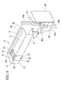
- a vehicle frame member structure 31 according to the embodiment shown in FIGS. 8 and 9A to 9C mainly has a closed cross-sectional structure including a pair of horizontal wall portions 2 and 3, and a pair of vertical wall portions 4 and 35 connected to the pair of the horizontal wall portions 2 and 3.
- the vehicle frame member structure 31 is constituted of a first member 8 which has a hat-shaped cross section and is constituted of the pair of horizontal wall portions 2 and 3, one vertical wall portion 4, a plate-like second member 39 constituting the other vertical wall portion 35, a first connecting member 41 and a second connecting member 42 attached to the tip end of the first member 8, and a third member 43 attached to the first connecting member 41 and the second connecting member 42.
- the pair of horizontal wall portions 2 and 3 of the first member 8 is provided with flange portions 6 and 7, respectively. Then, the first member 8 and the second member 39 are integrally connected by spot-welding of the second member 39 to the flange portions 6 and 7 of the first member 8 and thus the closed cross-sectional structure including the horizontal wall portions 2 and 3 and the vertical wall portions 4 and 35 is formed.
- the first connecting member 41 is provided for connecting the first member 8 and the third member 43.
- the first connecting member 41 is constituted of a first connecting portion 41 a which is connected to the ends of the upper and lower horizontal wall portions 2 and 3 and the vertical wall portion 4 of the first member 8, and a second connecting portion 41b which is formed to be bent from the first connecting portion 41 a and is connected to the third member 43.
- the second connecting member 42 is provided for connecting the first member 8, the second member 39, and the third member 43 to each other.
- the second connecting member 42 is constituted of a box-shaped main body 42a, a third connecting portion 42b, a fourth connecting portion 42c, a fifth connecting portion 42d, and a sixth connecting portion 42e.
- the third connecting portion 42b is formed to be bent from the main body 42a and is connected to the horizontal wall portion 3 on the lower side of the first member 8.
- the fourth connecting portion 42c is formed to be extended from the main body 42a and is connected to the vertical wall portion 4 of the first member 8.
- the fifth connecting portion 42d is formed to be bent from the main body 42a and is connected to the second member 39.
- the sixth connecting portion 42e is formed to be bent from the main body 42a and is connected to the third member 43.
- the third member 43 is attached to the first and second connecting members 41 and 42 so as to cover a closed cross-sectional opening constituted of the first and second members 8 and 39 and an opening constituted of the box-shaped main body 42a of the second connecting member 42.
- the third member 43 is connected to a flange portion 39a of the second member 39.
- the first member 8 is produced by press-forming the steel sheet to have a hat shape when seen from a cross section.
- high strength steel sheet for a vehicle is suitably used and particularly high strength thin steel sheet, such as TRIP steel, in which work hardening easily occurs is preferably used.
- high strength steel sheet for a vehicle is also suitably used for the second member 39, the first and second connecting members 41 and 42, and the third member 43 in the same manner.
- first beads 21 which are projected beads formed along a closed cross-sectional circumferential direction, are provided on the pair of horizontal wall portions 2 and 3 of the first member 8.
- the first beads 21 are each constituted of a pair of inclined surfaces inclined from the horizontal wall portion 2 or 3, and a flat surface parallel to the surface of the horizontal wall portion 2 or 3 and positioned at the center of the pair of inclined surfaces.
- a second bead 22 which is a recessed bead formed along the closed cross-sectional circumferential direction is provided on the vertical wall portion 4 of the first member 8.
- the second bead 22 is provided on the line extending from the first bead 21 in the closed cross-sectional circumferential direction. Then, the first beads 21 and the second bead 22 are connected at two corner portions 11 and 12, respectively. Connection portions 23 of the first and second beads 21 and 22 are corner portions constituted of the first beads 21 and the second bead 22. The connection portions 23 are placed at positions shifted from the corner portions 11 and 12 which connect the horizontal wall portions 2 and 3 and the vertical wall portion 4 by the height of the first beads 21 and the depth of the second bead 22.
- the first bead 21 shown in FIGS. 8 and 9A to 9C is a projected bead and the second bead 22 is a recessed bead.
- the present invention is not limited thereto.
- the first bead 21 may be a recessed bead and the second bead 22 may be a projected bead, or both the first bead 21 and the second bead 22 may be projected beads or recessed beads.
- recessed embossed portions 24 are provided in the portions of the respective connection portions 23 in which the first beads 21 and the second bead 22 are connected. It is preferable that the embossed portion 24 be constituted of two triangular wall surfaces 24a and 24b and the both triangular bottom sides be connected. In this case, the shape of the entire embossed portion 24 as seen from a plan view is a rectangular shape close to a rhombus. In addition, a portion in which the two triangular wall surfaces 24a and 24b are connected to each other is formed as a valley fold portion 24c along the closed cross-sectional circumferential direction.
- the embossed portion 24 is formed by recessing the corner portions 11 and 12 that are formed between the horizontal wall portions 2 and 3 and the vertical wall portion 4 when the steel sheet is press-formed and worked into the first member 8. Through such a process, the embossed portion 24 is formed as a thickened portion in which the peripheral steel is dammed up. Accordingly, the sheet thickness of the embossed portion 24 is larger than the sheet thickness of the horizontal wall portion 2 and 3 or the vertical wall portion 4.
- the sheet thickness of the embossed portion 24 is preferably about 1.1 times to 1.4 times, and more preferably about 1.15 times to 1.2 times of the sheet thickness of the horizontal wall portions 2 and 3 or the vertical wall portion 4.
- the embossed portion 24 has a higher hardness than the hardness of the horizontal wall portions 2 and 3 or the vertical wall portion 4.
- the embossed portion 24 may be provided in only one of two connection portions of the two first beads 21 and 21 provided on the pair of horizontal wall portions 2 and 3 and the second bead 22 provided on the vertical wall portion 4. Particularly, when it is assumed that a bending moment is applied to the frame member structure 1, it is preferable that the embossed portion 24 be provided in only a portion corresponding to the inner peripheral side of deflection caused by the bending moment. In the embodiment, it is preferable that the embossed portion 24 be provided on the side close to the horizontal wall portion 3 corresponding to the inner peripheral side of the deflection. When the bending moment is applied to the frame member structure 31, compression stress is concentrated on the inner peripheral side of the deflection.
- the embossed portion 24 when the embossed portion 24 is provided on the inner peripheral side, the first and second beads 21 and 22 can be reinforced. Further, the embossed portion 24 may be provided on both of the two connection portions of the first beads 21 and the second bead 22. When the embossed portions are provided in both the connection portions, the stress concentration can be dispersed.
- the frame member structure 31 according to the embodiment is applied to a structural member, such as a front side member of a vehicle, to which an impact load is applied from the axial direction.
- the front side member is constituted of an outer panel arranged on the outer side of the vehicle width direction and an inner panel arranged on the inner side of the vehicle width direction.
- the frame member structure 31 according to the embodiment can be applied to a front side member having the first member 8 as an inner panel and the second member 39 as an outer panel.
- the third member 43 can be applied to a part of the front cross member.
- the load is applied to the front side member in the axial direction and it is necessary that the front side member be reliably axially compression-deformed without bending at the axial intermediate portion to reliably absorb the impact energy at the time of impact.
- the reaction force to the impact load is small, buckling easily occurs with a smaller impact load.
- the first beads 21 and the second bead 22 function as a starting point of axial compression deformation when an impact load is applied and the crushing deformation of the horizontal wall portions 2 and 3 and the vertical wall portion 4 around the first beads 21 and the second bead 22 is promoted so that the frame member structure can absorb the impact energy.
- the impact load input to the third member 43 is input to the first member 8 through the first and second connecting members 41 and 42.
- the second connecting member 42 is easily crushed.
- a bending moment may be applied to the first member 8.
- the embossed portion 24 is provided in the connection portion of the first bead 21 and the second bead 22, the deflective strength of the first bead 21 and the second bead 22 on which the reaction force of the bending moment is relatively easily concentrated can be increased. Therefore, the frame member structure 31 can be prevented from being bent until the frame member structure 31 absorbs the impact energy sufficiently.
- the sheet thickness of the embossed portion 24 is larger than the sheet thickness of the horizontal wall portions 2 and 3 or the vertical wall portion 4, the rigidity of the horizontal wall portions 2 and 3 and the vertical wall portion 4 around the first beads 21 and the second bead 22 is increased and thus the deflective strength is further improved. Therefore, the reaction force to the deflection deformation caused by the bending moment is further improved and the impact resistance performance can be further improved.
- the embossed portion 24 is constituted of the two triangular wall surfaces 24a and 24b, the shape of the embossed portion 24 is simple and thus the embossed portion is easily press-formed. Therefore, the amount of strain accompanied by a reduction in the sheet thickness is small and thus the deflective strength of the horizontal wall portions 2 and 3 and the vertical wall portion 4 around the first beads 21 and the second bead 22 can be prevented from being lowered.
- the embossed portion is provided on only an inner peripheral corner portion of the deflection caused by the bending moment in the vehicle frame member structure 31 out of the two corner portions 11 and 12, the deflective strength of the horizontal wall portions 2 and 3 and the vertical wall portion 4 around the first beads 21 and the second bead 22 can be further improved. Therefore, the reaction force to the deflection deformation caused by the bending moment is further improved and thus the impact resistance performance can be further improved.
- a frame member structure shown in FIGS. 8 and 9A to 9C was produced and the impact performance thereof was evaluated.
- a frame member structure 31 shown in FIGS. 8 and 9A to 9C is Example 2 and a frame member structure 31' shown in FIGS. 10A to 10C is Comparative example 2.
- Comparative example 2 shown in FIGS. 10A to 10C has the same configuration as that of Example 2 shown in FIGS. 8 and 9A to 9C except that the embossed portion is not provided.
- an axial length L is 300 mm
- a total width W 1 of the first member 8 and the second member 39 is 100 mm
- a width W 2 of the vertical wall portion 4 is 60 mm
- a width W 3 of each of the horizontal wall portions 2 and 3 is 60 mm.
- the total width of the first bead 21 to the closed cross-sectional circumferential direction is 50 mm
- the projection height of the first bead 21 is 3 mm
- the total width of the second bead 22 to the closed cross-sectional circumferential direction is 50 mm
- the depth of the second bead 22 is 3 mm.
- the projection length of the main body 42a of the second connecting member 42 from the horizontal wall portion 3 on the lower side of the first member 8 is 60 mm
- the axial length of the main body 42a is 60 mm
- the width of the main body 42a is 60mm.
- the embossed portion 24 is provided at a position away from one end 31 a by a distance of 60 mm.
- the total width of the embossed portion 24 to the closed cross-sectional circumferential direction is 30 mm
- the length of the embossed portion 24 on each of the horizontal wall portions 2 and 3 along the closed cross-sectional circumferential direction is 15 mm
- the length of the embossed portion 24 on the vertical wall portion 4 along the closed cross-sectional circumferential direction is 15 mm.
- Example 2 and Comparative example 2 an impact test was performed in Example 2 and Comparative example 2 by allowing a falling weight 101 having a mass of 400 kg to freely fall from a height of 3 m as shown in FIG 11A .
- the impact speed of the falling weight 101 was 7.67 m/s and the energy to be input to the frame member structure by the falling weight 101 was 11.8 kJ.
- the falling weight 101 was formed to have a surface in contact with the structural body to be inclined at an angle of 8 degrees as shown in FIG. 11A so that the bending moment acted when the structural body was impacted with the falling weight 101.
- a load measuring unit load cell
- a load history was measured.
- the displacement history of the falling weight 101 was also measured by a laser displacement gauge.
- Example 2 an example in which the embossed portions 24 are provided on both the left and the right sides of the drawing is Example 2, and an example in which the embossed portion 24 is not provided is Comparative example 2.
- Example 3 as an example in which the embossed portion 24 was provided on only the right side of the drawing was prepared and Comparative example 3 as an example in which the first and the second beads 21 and 22 and the embossed portion 24 are not provided was prepared.
- the impact test shown in FIG. 11A was also performed in Example 3 and Comparative example 3.
- the position of the embossed portion of Example 3 corresponds to the position of the inner peripheral side of the deflection when the bending moment is applied.
- a peak reaction force was calculated from the obtained load-displacement diagram and was set as an index for evaluating the impact absorption capacity.
- the load-displacement diagram until 100 mm displacement occurred from the contact of the falling weight with the structural body was integrated to calculate the absorbed energy and thus the obtained value was set as a value for evaluating the impact absorption capacity. The results are shown in Table 2.
Landscapes
- Engineering & Computer Science (AREA)
- Mechanical Engineering (AREA)
- Chemical & Material Sciences (AREA)
- Combustion & Propulsion (AREA)
- Transportation (AREA)
- Body Structure For Vehicles (AREA)
Abstract
Description
- The present invention relates to a vehicle frame member structure having excellent impact resistance performance.
- Priority is claimed on Japanese Patent Application No.
2012-127441, filed on June 4, 2012 - It is necessary that a frame member such as a front side member of a vehicle be designed such that the maximum reaction force of the frame member has an appropriate value when an impact load is applied. The maximum reaction force of the frame member varies depending on the material and shape of the member and thus a number of parameters have to be considered when the frame member is designed.
- For example, in order to reduce the weight of a vehicle, when the thickness of a steel sheet constituting the frame member is reduced, the maximum reaction force of the frame member is reduced and thus the structural member is easily buckled. Therefore, it is necessary to design a frame member having a high maximum reaction force while reducing the weight of the vehicle by reducing the thickness of the steel sheet.
- In
Patent Document 1 below, there is disclosed a vehicle frame member having a closed cross-sectional structure in which recessed stripes provided on wall portions that face each other are continued to a projected stripe which is provided on one wall portion and interposed between these wall portions through corner portions. When an input load is input to the vehicle frame member in a compression direction, stress is concentrated on the recessed stripes and the projected stripe and crushing deformation of the corner portion is promoted. Thus, the wall portions are crushed and deformed around the recessed stripes and the projected stripe. - In addition, in
Patent Document 2 below, there is disclosed a frame member structure including plural first beads arranged on at least one wall portion of wall portions constituting each side having a polygonal closed cross-sectional shape with predetermined intervals, and plural second beads arranged at positions that do not overlap the axial positions of the first beads on a wall portion adjacent to the wall portion on which the first beads are provided. With the frame member structure, stable axial compression deformation using both the first beads and the second beads as a starting point can be obtained and thus the initial buckling load can be increased. -
- [Patent Document 1] Japanese Unexamined Patent Application, First Publication No.
H4-231268 - [Patent Document 2] Japanese Unexamined Patent Application, First Publication No.
2001-158377 - However, in a case of a front side member as an example of a frame member, an engine is mounted on the front side member through an engine mount and a load of the engine is constantly applied thereto. In addition, a front cross member is connected to the tip end of the front side member through a coupling member, and a load is applied through the front cross member at the time of impact. Therefore, the input load at the time of impact may be applied from a direction that is slightly shifted from the axial direction of the front side member. Further, there is a case in which the front side member is attached at an angle slightly inclined to the longitudinal direction of a vehicle and even in this case, the input load at the time of impact may be applied from a direction that is slightly shifted from the axial direction of the front side member.
- As described above, a load is usually input to the front side member, and further, the input load at the time of impact may be applied from a direction that is slightly shifted from the axial direction of the front side member and thus a bending moment may be applied at the time of impact. Therefore, when the frame member described in
Patent Document - The present invention is made in consideration of the above-described problems and an object thereof is to provide a vehicle frame member structure having excellent impact resistance performance.
- The gist of the present invention is as follows.
- (1) According to a first aspect of the present invention, there is provided a vehicle frame member structure having a closed cross-sectional structure including a pair of first wall portions, and a pair of second wall portions connected to the pair of the first wall portions, in which first beads are provided on the pair of first wall portions along a circumferential direction of the closed cross-sectional structure, a second bead is provided on either of the pair of second wall portions along the closed cross-sectional circumferential direction on a line extending from the first bead in the circumferential direction, the first beads and the second bead are connected to each other in two corner portions between the first wall portions and the second wall portion, a recessed embossed portion is provided in a connection portion of the first bead and the second bead in at least one of the corner portions, and the sheet thickness of the embossed portion is larger than the sheet thickness of one of the first wall portion and the second wall portion.
- (2) In the vehicle frame member structure according to (1), the first bead may have a first flat surface parallel to a surface of the first wall portion, the second bead may have a second flat surface parallel to a surface of the second wall portion, and the embossed portion may be provided in a connection portion of the first flat surface and the second flat surface.
- (3) In the vehicle frame member structure according to (1) or (2), the embossed portion may be constituted of two triangular wall surfaces.
- (4) In the vehicle frame member structure according to any one of (1) to (3), of the two corner portions, the embossed portion may be provided in only an inner peripheral corner portion of deflection caused by a bending moment that is applied to the vehicle frame member structure at the time of impact.
- (5) In the vehicle frame member structure according to any one of (1) to (4), any one of the first bead and the second bead may be a projected bead and the other thereof may be a recessed bead.
- According to the vehicle frame member structure described in (1), since the recessed embossed portion is provided in the connection portion of the first bead and the second bead in at least one of the corner portions, the deflective strength of the first wall portion and the second wall portion around the first bead and the second bead is improved and the reaction force to deflection deformation caused by a bending moment is improved and thus the impact resistance performance can be improved. Further, since the sheet thickness of the embossed portion is larger than the sheet thickness of the first wall portion or the second wall portion, the rigidity of the first wall portion and the second wall around the first bead and the second bead is improved and the deflective strength is further improved. Accordingly, the reaction force to deflection deformation caused by a bending moment is further improved and thus the impact resistance performance can be further improved.
- According to the vehicle frame member structure described in (2), since the first bead has a first flat surface parallel to a surface of the first wall portion, the second bead has a second flat surface parallel to a surface of the second wall portion, and the embossed portion is provided in a connection portion of the first flat surface and the second flat surface, the deflective strength of the first wall portion and the second wall portion around the first bead and the second bead is further improved. Accordingly, the reaction force to deflection deformation caused by a bending moment is improved and thus the impact resistance performance can be improved.
- According to the vehicle frame member structure described in (3), since the embossed portion is constituted of two triangular wall surfaces, the shape of the embossed portion is simple and thus the embossed portion is easily press-formed. In addition, the amount of strain accompanied by a reduction in the sheet thickness is small and the deflective strength of the first wall portion and the second wall portion around the first bead and the second bead can be prevented from being lowered.
- According to the vehicle frame member structure described in (4), since the embossed portion is provided in only an inner peripheral corner portion of deflection caused by a bending moment in the vehicle frame member structure out of the two corner portions, the deflective strength of the first wall portion and the second wall portion around the first bead and the second bead is further improved and the reaction force to deflection deformation caused by the bending moment is further improved and thus the impact resistance performance can be further improved.
- According to the vehicle frame member structure described in (5), since any one of the first bead and the second bead is a projected bead and the other thereof is a recessed bead, stress is concentrated on the first bead and the second bead and crushing deformation of the corner portion is promoted. Thus, the first wall portion and the second wall portion are crushed and deformed around the first bead and the second bead, and the vehicle frame member structure can absorb the impact energy effectively.
-
-
FIG. 1A is a side view showing a vehicle frame member structure according to a first embodiment of the present invention. -
FIG. 1B is a plan view corresponding to the side view ofFIG. 1A . -
FIG. 1C is a perspective view corresponding to the side view ofFIG. 1A . -
FIG. 2A is a perspective view showing the vehicle frame member structure according to the first embodiment of the present invention. -
FIG. 2B is an enlarged perspective view of an embossed portion of the structure. -
FIG. 2C is an enlarged cross-sectional view of the embossed portion corresponding to line Z-Z' ofFIG. 2B . -
FIG. 3A is a side view showing an example of a vehicle frame member structure of the related art. -
FIG. 3B is a plan view corresponding to the side view ofFIG. 3A . -
FIG. 3C is a perspective view corresponding to the side view ofFIG. 3A . -
FIG. 4A is a perspective view showing sheet thickness distribution of an example of the related art. -
FIG. 4B is a perspective view showing sheet thickness distribution of the embossed portion of an example of the present invention. -
FIG. 5 is a schematic view showing an impact absorbing test method in Example 1 and Comparative example 1. -
FIG. 6 is a diagram showing results of an impact absorbing test in Example 1 and Comparative example 1 and is a graph showing a relationship between the amount of crushing deformation of the vehicle frame member structure and a load cell load. -
FIG. 7A is a view showing a member deformation state when 1 millisecond has elapsed after a falling weight is impacted during the impact absorbing test and is a front view showing a deformation state of Comparative example 1. -
FIG. 7B is a perspective view corresponding to the front view ofFIG. 7A . -
FIG. 7C is a view showing a member deformation state when 1 millisecond has elapsed after a falling weight is impacted during the impact absorbing test and is a front view showing a deformation state of Example 1. -
FIG. 7D is a perspective view corresponding to the front view ofFIG. 7C . -
FIG. 8 is an exploded perspective view showing a vehicle frame member structure according to a second embodiment of the present invention. -
FIG. 9A is a side view showing the vehicle frame member structure according to the second embodiment of the present invention. -
FIG 9B is a plan view corresponding to the side view ofFIG 9A . -
FIG. 9C is a perspective view corresponding to the side view ofFIG 9A . -
FIG. 10A is a side view showing another example of a vehicle frame member structure of the related art. -
FIG 10B is a plan view corresponding to the side view ofFIG. 10A . -
FIG. 10C is a perspective view corresponding to the side view ofFIG. 10A . -
FIG. 11A is a schematic view showing an impact absorbing test method in Examples 2 and 3 and Comparative examples 2 and 3. -
FIG 11B is a schematic view showing a deflection curve of the vehicle frame member structure during an impact absorbing test. - Hereinafter, a first embodiment and examples of the present invention will be described with reference to drawings.
- As shown in
FIGS. 1A to 1C and2A to 2C , a vehicleframe member structure 1 according to an embodiment has a closed cross-sectional structure including a pair of first wall portions (hereinafter, referred to ashorizontal wall portions 2 and 3), and a pair of second wall portions connected to the pair ofhorizontal wall portions 2 and 3 (hereinafter, referred to asvertical wall portions 4 and 5). For example, the vehicleframe member structure 1 includes afirst member 8 which has a hat-shaped cross section and is constituted of the pair ofhorizontal wall portions vertical wall portion 4, and a plate-like second member 9 constituting the othervertical wall portion 5. The pair ofhorizontal wall portions first member 8 are provided withflange portions first member 8 and the second member 9 are integrally connected by spot-welding of the second member 9 to theflange portions first member 8 and thus the closed cross-sectional structure including thehorizontal wall portions vertical wall portions - The
first member 8 is produced by press-forming a steel sheet to have a hat shape when seen from a cross section. As the steel sheet constituting thefirst member 8, high strength steel sheet for a vehicle is suitably used and particularly high strength thin steel sheet, such as TRIP steel, in which work hardening easily occurs is preferably used. High strength steel sheet for a vehicle is also suitably used for the second member 9 in the same manner. - The pair of
horizontal wall portions vertical wall portion 4 of thefirst member 8 are connected to each other through thecorner portions first beads 21, which are projected beads formed along a closed cross-sectional circumferential direction, are provided on the pair ofhorizontal wall portions first member 8. Thefirst beads 21 are each constituted of a pair of inclined surfaces inclined from thehorizontal wall portion horizontal wall portion second bead 22, which is a recessed bead formed along the closed cross-sectional circumferential direction, is provided on thevertical wall portion 4 of thefirst member 8. Thesecond bead 22 is provided on the line extending from thefirst bead 21 in the closed cross-sectional circumferential direction. Thesecond bead 22 is constituted of a pair of inclined surfaces inclined from thevertical wall portion 4 and a flat surface parallel to the surface of thevertical wall portion 4 and positioned at the center of the pair of inclined surfaces. Then, thefirst beads 21 and thesecond bead 22 are connected to each other at twocorner portions Connection portions 23 of the first andsecond beads first beads 21 and thesecond bead 22. Theconnection portions 23 are placed at positions shifted from thecorner portions horizontal wall portions vertical wall portion 4 by the height of thefirst beads 21 and the depth of thesecond bead 22. As shown inFIGS. 1A to 1C and2A to 2C , thefirst bead 21 is a projected bead and thesecond bead 22 is a recessed bead. However, the present invention is not limited thereto. For example, thefirst bead 21 may be a recessed bead and thesecond bead 22 may be a projected bead, or both thefirst bead 21 and thesecond bead 22 may be projected beads or recessed beads. - Next, as shown in
FIGS. 1A to 1C and2A to 2C , recessedembossed portions 24 are provided in theconnection portions 23 of thefirst beads 21 and thesecond bead 22 at therespective corner portions portion 24 be constituted of two triangular wall surfaces 24a and 24b and both the triangular bottom sides be connected. In this case, the shape of the entire embossedportion 24 as seen from a plan view is a rectangular shape close to a rhombus. In addition, a portion in which the two triangular wall surfaces 24a and 24b are connected to each other is formed as avalley fold portion 24c along the closed cross-sectional circumferential direction. - The embossed
portion 24 is formed by recessing thecorner portions horizontal wall portions vertical wall portion 4 when the steel sheet is press-formed and worked into thefirst member 8. Since such a process is performed, the embossedportion 24 is formed as a thickened portion in which the peripheral steel is dammed up. Accordingly, the sheet thickness of the embossedportion 24 is larger than the sheet thickness of thehorizontal wall portion vertical wall portion 4. The sheet thickness of the embossedportion 24 is preferably about 1.1 times to 1.4 times, and more preferably about 1.15 times to 1.2 times of the sheet thickness of thehorizontal wall portions vertical wall portion 4. Further, since the amount of working of the embossedportion 24 is larger than that of the peripheral portion, the work hardening of the embossedportion 24 is promoted. Thus, the embossedportion 24 has a higher hardness than the hardness of thehorizontal wall portions vertical wall portion 4. - In addition, the embossed
portion 24 may be provided in only one of two connection portions of the twofirst beads horizontal wall portions second bead 22 provided on thevertical wall portion 4. Particularly, when it is assumed that a bending moment is applied to theframe member structure 1 at the time of impact, it is preferable that the embossedportion 24 be provided in only a portion corresponding to the inner peripheral side of deflection caused by the bending moment. When the bending moment is applied to theframe member structure 1, compression stress is concentrated on the inner peripheral side of the deflection. However, when the embossedportion 24 is provided on the inner peripheral side, the first andsecond beads FIGS. 1A to 1C and2A to 2C , theembossed portions 24 may be provided on both of the two connection portions of thefirst beads 21 and thesecond bead 22. When the embossed portions are provided in both the connection portions, the stress concentration occurring when an impact load is input can be dispersed. - For example, the
frame member structure 1 according to the embodiment is applied to a structural member, such as a front side member of a vehicle, to which an impact load is applied from the axial direction. The front side member is constituted of an outer panel arranged on the outer side of the vehicle width direction and an inner panel arranged on the inner side of the vehicle width direction. For example, theframe member structure 1 according to the embodiment can be applied to a front side member having thefirst member 8 as an inner panel and the second member 9 as an outer panel. - In addition, when an impact load is applied to a vehicle, the load is applied to the front side member in the axial direction and it is necessary that the front side member be reliably axially compression-deformed without bending at the axial intermediate portion to reliably absorb the impact energy at the time of impact. When the reaction force to the impact load is small, buckling easily occurs with a smaller impact load. Thus, it is necessary to set the reaction force to the impact load to be equal to or larger than a predetermined magnitude.
- In order to solve the above problem, in the
frame member structure 1 according to the embodiment, thefirst beads 21 and thesecond bead 22 function as a starting point of axial compression deformation when an impact load is applied and the crushing deformation of thehorizontal wall portions vertical wall portion 4 around thefirst beads 21 and thesecond bead 22 is promoted so that the frame member structure can absorb the impact energy. Further, even when the bending moment is applied to theframe member structure 1 when the impact load is input, theembossed portions 24 are provided in the connection portions of thefirst beads 21 and thesecond bead 22 and thus the deflective strength of thefirst beads 21 and thesecond bead 22 on which the stress of the bending moment is relatively easily concentrated can be increased. Therefore, theframe member structure 1 can be prevented from being bent until theframe member structure 1 sufficiently absorbs the impact energy. - Since the sheet thickness of the embossed
portion 24 is larger than the sheet thickness of thehorizontal wall portions vertical wall portion 4, the rigidity of thehorizontal wall portions vertical wall portion 4 around thefirst beads 21 and thesecond bead 22 increases and the deflective strength is further improved. Further, the reaction force to the deflection deformation caused by the bending moment can be further improved and the impact resistance performance can be further improved. - Further, when the embossed
portion 24 is constituted of the two triangular wall surfaces 24a and 24b, the shape of the embossedportion 24 is simple and thus the embossed portion is easily press-formed. Therefore, the amount of strain accompanied by a reduction in the sheet thickness is small and thus the deflective strength of thehorizontal wall portions vertical wall portion 4 around thefirst beads 21 and thesecond bead 22 can be prevented from being lowered. - In addition, when the embossed portion is provided on only an inner peripheral corner portion of the deflection caused by the bending moment in the vehicle
frame member structure 1 out of the twocorner portions horizontal wall portions vertical wall portion 4 around thefirst beads 21 and thesecond bead 22 can be further improved. Therefore, the reaction force to the deflection deformation caused by the bending moment is further improved and thus the impact resistance performance can be further improved. - Frame member structures shown in
FIGS. 1A to 1C ,2A to 2C , and3A to 3C were produced and the impact performance thereof was evaluated. Aframe member structure 1 shown inFIGS. 1A to 1C and2A to 2C is Example 1 and a frame member structure 1' shown inFIGS. 3A to 3C is Comparative example 1. Comparative example 1 shown inFIGS. 3A to 3C has the same configuration as that of Example 1 shown inFIGS. 1A to 1C and2A to 2C except that the embossed portion is not provided. - When the frame member structures shown in
FIGS. 1A to 1C ,2A to 2C , and3A to 3C were prepared, a steel sheet shown in Table 1 was press-formed to form the first member having a hat shape when seen from a cross section. In addition, the plate-like second member was formed by using the steel sheet shown in Table 1. Then, the first member and the second member were spot-welded to produce a vehicle frame member structure having a closed cross-sectional structure. The interval of the spot-welding in the longitudinal direction is 15 mm at both upper and lower ends only and 30 mm in portions other than the upper and lower ends.[Table 1] Steel type t/mm Mechanical properties Yield stress/MPa Tensile strength/MPa Elongation/% 780 MPa-class steel sheet 1.5 493 844 27 - In the vehicle frame member structures shown in
FIGS. 1A to 1C ,2A to 2C , and3A to 3C , an axial length L is 300 mm, a total width W1 thereof is 100 mm, a width W2 of each of thehorizontal wall portions vertical wall portion 4 is 60 mm. Further, the total width of thefirst bead 21 to the closed cross-sectional circumferential direction is 50 mm, the projection height of thefirst bead 21 is 3 mm, the total width of thesecond bead 22 to the closed cross-sectional circumferential direction is 50 mm, and the depth of thesecond bead 22 is 3 mm. - In Example 1 shown in
FIGS. 1A to 1C and2A to 2C , the embossedportion 24 is provided at a position away from oneend 1 a by a distance of 60 mm. A total width W4 of the embossedportion 24 to the closed cross-sectional circumferential direction is 30 mm, a length H1 of the embossedportion 24 on each of thehorizontal wall portions portion 24 on thevertical wall portion 4 along the closed cross-sectional circumferential direction is 15 mm. - Here, the measurement results of the sheet thickness of the embossed portion will be described with reference to
FIGS. 4A and 4B. FIG 4A is a perspective view showing the sheet thickness distribution of Comparative example 1, andFIG. 4B is a perspective view showing the sheet thickness distribution of the embossed portion of Example 1. As shown inFIG. 4A , the maximum sheet thickness of Comparative example 1 is about 1.6 mm at a position corresponding to the portion in which the embossed portion of Example 1 is formed and thus it is found that there is little difference between the maximum sheet thickness of Comparative example 1 and the thickness of the steel sheet of 1.5 mm. On the other hand, as shown inFIG 4B , the maximum sheet thickness of the embossed portion of Example 1 is more than 1.72 mm and thus the thickness of the embossed portion is larger than the thickness of the steel sheet of 1.5 mm. - Next, an impact test was performed in Example 1 and Comparative example 1 by allowing a falling
weight 100 having a mass of 400 kg to freely fall from a height of 3 m as shown inFIG. 5 . At this time, the impact speed of the fallingweight 100 was 7.67 m/s and the energy to be input to the frame member structure by the fallingweight 100 was 11.8 kJ. In addition, after a load measuring unit (load cell) was arranged immediately below the frame member structure and the fallingweight 100 was brought into contact with the frame member structure, a load history was measured. At the same time, the displacement history of the falling weight was also measured by a laser displacement gauge. - The measurement results are shown in
FIGS. 6 and7A to 7D . As shown inFIG 6 , an initial peak reaction force in Comparative example 1 is 205 kN, whereas an initial peak reaction force in Example 1 is 230 kN, and thus the initial peak reaction force in Example 1 is larger than that of Comparative example 1. In addition, when comparing the absorbed energies of the members when the amount of crushing deformation is 100 mm, the absorbed energy of Comparative example 1 is 7799 J, whereas the absorbed energy of Example 1 is 7077 J, and thus, the absorbed energy is increased. - In addition, in
FIGS. 7A to 7D , the deformation of the members when 1 millisecond has elapsed from the falling weight impact is shown. The contour line ofFIGS. 7A to 7D represent the amount of plastic strain. The amount of plastic strain which is input when the frame member structure is formed is divided and displayed. That is, inFIGS. 7A to 7D , only the amount of plastic strain input by the impact of the falling weight is displayed. - As shown in
FIGS. 7A and 7B , in Comparative example 1, it is found that the reaction force is defined such that deformation is concentrated on the upper end of the corner portion in which the first bead and the second bead are connected to each other and the upper end is deformed immediately after the impact. On the other hand, as shown inFIGS. 7C and 7D , in Example 1, it is found that the reaction force is defined such that deformation is concentrated on the straight line connecting between the arranged embossed portions and the embossed portions are deformed immediately after the impact. When comparing to the sheet thickness distribution ofFIGS. 4A and 4B , a significant increase in the sheet thickness is not observed at the reaction force definition position of Comparative example 1 when the member is formed. Contrarily, a significant increase in the sheet thickness is observed at the reaction force definition position (embossed portion) of Example 1. In Example 1, it is considered that since the sheet thickness is increased when the embossed portion is formed and the amount of working hardening input from the sheet thickness increasing working is large, the deformation resistance of the embossed portion is high and the initial peak reaction force is increased. - Further, as seen from
FIG. 6 , the reason why the absorbed energy is increased is that the reaction force increases until the amount of crushing deformation reaches 60 mm, in which crushing of the first and second bead portions is completed by the same principle as in the above-described increase in the initial peak reaction force. The absorbed energy is obtained by integrating the reaction force history ofFIG. 6 and thus it is considered that the absorbed energy also increases by the same principle as in the above-described increase in the initial peak reaction force. - Next, a second embodiment and examples of the present invention will be described with reference to the drawings. Among components in the embodiment, the same reference numerals used in the description of the first embodiment are assigned to components similar to those described in the first embodiment and a description thereof will be provided.
- A vehicle
frame member structure 31 according to the embodiment shown inFIGS. 8 and9A to 9C mainly has a closed cross-sectional structure including a pair ofhorizontal wall portions vertical wall portions horizontal wall portions frame member structure 31 is constituted of afirst member 8 which has a hat-shaped cross section and is constituted of the pair ofhorizontal wall portions vertical wall portion 4, a plate-likesecond member 39 constituting the othervertical wall portion 35, a first connectingmember 41 and a second connectingmember 42 attached to the tip end of thefirst member 8, and athird member 43 attached to the first connectingmember 41 and the second connectingmember 42. - The pair of
horizontal wall portions first member 8 is provided withflange portions first member 8 and thesecond member 39 are integrally connected by spot-welding of thesecond member 39 to theflange portions first member 8 and thus the closed cross-sectional structure including thehorizontal wall portions vertical wall portions - In addition, the first connecting
member 41 is provided for connecting thefirst member 8 and thethird member 43. The first connectingmember 41 is constituted of a first connectingportion 41 a which is connected to the ends of the upper and lowerhorizontal wall portions vertical wall portion 4 of thefirst member 8, and a second connectingportion 41b which is formed to be bent from the first connectingportion 41 a and is connected to thethird member 43. - Further, the second connecting
member 42 is provided for connecting thefirst member 8, thesecond member 39, and thethird member 43 to each other. The second connectingmember 42 is constituted of a box-shapedmain body 42a, a third connectingportion 42b, a fourth connectingportion 42c, a fifth connectingportion 42d, and a sixth connectingportion 42e. The third connectingportion 42b is formed to be bent from themain body 42a and is connected to thehorizontal wall portion 3 on the lower side of thefirst member 8. The fourth connectingportion 42c is formed to be extended from themain body 42a and is connected to thevertical wall portion 4 of thefirst member 8. The fifth connectingportion 42d is formed to be bent from themain body 42a and is connected to thesecond member 39. The sixth connectingportion 42e is formed to be bent from themain body 42a and is connected to thethird member 43. - The
third member 43 is attached to the first and second connectingmembers second members main body 42a of the second connectingmember 42. In addition, thethird member 43 is connected to aflange portion 39a of thesecond member 39. - The
first member 8 is produced by press-forming the steel sheet to have a hat shape when seen from a cross section. As the steel sheet constituting thefirst member 8, as in the first embodiment, high strength steel sheet for a vehicle is suitably used and particularly high strength thin steel sheet, such as TRIP steel, in which work hardening easily occurs is preferably used. In addition, high strength steel sheet for a vehicle is also suitably used for thesecond member 39, the first and second connectingmembers third member 43 in the same manner. - The pair of
horizontal wall portions vertical wall portion 4 of thefirst member 8 are connected to each other through thecorner portions first beads 21, which are projected beads formed along a closed cross-sectional circumferential direction, are provided on the pair ofhorizontal wall portions first member 8. Thefirst beads 21 are each constituted of a pair of inclined surfaces inclined from thehorizontal wall portion horizontal wall portion second bead 22 which is a recessed bead formed along the closed cross-sectional circumferential direction is provided on thevertical wall portion 4 of thefirst member 8. Thesecond bead 22 is provided on the line extending from thefirst bead 21 in the closed cross-sectional circumferential direction. Then, thefirst beads 21 and thesecond bead 22 are connected at twocorner portions Connection portions 23 of the first andsecond beads first beads 21 and thesecond bead 22. Theconnection portions 23 are placed at positions shifted from thecorner portions horizontal wall portions vertical wall portion 4 by the height of thefirst beads 21 and the depth of thesecond bead 22. - The
first bead 21 shown inFIGS. 8 and9A to 9C is a projected bead and thesecond bead 22 is a recessed bead. However, the present invention is not limited thereto. For example, thefirst bead 21 may be a recessed bead and thesecond bead 22 may be a projected bead, or both thefirst bead 21 and thesecond bead 22 may be projected beads or recessed beads. - Next, as shown in
FIGS. 8 and9A to 9C , recessedembossed portions 24 are provided in the portions of therespective connection portions 23 in which thefirst beads 21 and thesecond bead 22 are connected. It is preferable that the embossedportion 24 be constituted of two triangular wall surfaces 24a and 24b and the both triangular bottom sides be connected. In this case, the shape of the entire embossedportion 24 as seen from a plan view is a rectangular shape close to a rhombus. In addition, a portion in which the two triangular wall surfaces 24a and 24b are connected to each other is formed as avalley fold portion 24c along the closed cross-sectional circumferential direction. - The embossed
portion 24 is formed by recessing thecorner portions horizontal wall portions vertical wall portion 4 when the steel sheet is press-formed and worked into thefirst member 8. Through such a process, the embossedportion 24 is formed as a thickened portion in which the peripheral steel is dammed up. Accordingly, the sheet thickness of the embossedportion 24 is larger than the sheet thickness of thehorizontal wall portion vertical wall portion 4. The sheet thickness of the embossedportion 24 is preferably about 1.1 times to 1.4 times, and more preferably about 1.15 times to 1.2 times of the sheet thickness of thehorizontal wall portions vertical wall portion 4. Further, since the amount of working of the embossedportion 24 is larger than that of the peripheral portion, the work hardening of the embossedportion 24 is promoted. Thus, the embossedportion 24 has a higher hardness than the hardness of thehorizontal wall portions vertical wall portion 4. - In addition, the embossed
portion 24 may be provided in only one of two connection portions of the twofirst beads horizontal wall portions second bead 22 provided on thevertical wall portion 4. Particularly, when it is assumed that a bending moment is applied to theframe member structure 1, it is preferable that the embossedportion 24 be provided in only a portion corresponding to the inner peripheral side of deflection caused by the bending moment. In the embodiment, it is preferable that the embossedportion 24 be provided on the side close to thehorizontal wall portion 3 corresponding to the inner peripheral side of the deflection. When the bending moment is applied to theframe member structure 31, compression stress is concentrated on the inner peripheral side of the deflection. Thus, when the embossedportion 24 is provided on the inner peripheral side, the first andsecond beads portion 24 may be provided on both of the two connection portions of thefirst beads 21 and thesecond bead 22. When the embossed portions are provided in both the connection portions, the stress concentration can be dispersed. - For example, the
frame member structure 31 according to the embodiment is applied to a structural member, such as a front side member of a vehicle, to which an impact load is applied from the axial direction. The front side member is constituted of an outer panel arranged on the outer side of the vehicle width direction and an inner panel arranged on the inner side of the vehicle width direction. Theframe member structure 31 according to the embodiment can be applied to a front side member having thefirst member 8 as an inner panel and thesecond member 39 as an outer panel. Further, thethird member 43 can be applied to a part of the front cross member. - In addition, when an impact load is applied to a vehicle, the load is applied to the front side member in the axial direction and it is necessary that the front side member be reliably axially compression-deformed without bending at the axial intermediate portion to reliably absorb the impact energy at the time of impact. When the reaction force to the impact load is small, buckling easily occurs with a smaller impact load. Thus, it is necessary to set the reaction force to the impact load to be equal to or larger than a predetermined magnitude.
- In order to solve the above problem, in the
frame member structure 31 according to the embodiment, thefirst beads 21 and thesecond bead 22 function as a starting point of axial compression deformation when an impact load is applied and the crushing deformation of thehorizontal wall portions vertical wall portion 4 around thefirst beads 21 and thesecond bead 22 is promoted so that the frame member structure can absorb the impact energy. - In the
frame member structure 31 according to the embodiment, the impact load input to thethird member 43 is input to thefirst member 8 through the first and second connectingmembers member 42 is easily crushed. Thus, a bending moment may be applied to thefirst member 8. Even in this case, since the embossedportion 24 is provided in the connection portion of thefirst bead 21 and thesecond bead 22, the deflective strength of thefirst bead 21 and thesecond bead 22 on which the reaction force of the bending moment is relatively easily concentrated can be increased. Therefore, theframe member structure 31 can be prevented from being bent until theframe member structure 31 absorbs the impact energy sufficiently. - In addition, since the sheet thickness of the embossed
portion 24 is larger than the sheet thickness of thehorizontal wall portions vertical wall portion 4, the rigidity of thehorizontal wall portions vertical wall portion 4 around thefirst beads 21 and thesecond bead 22 is increased and thus the deflective strength is further improved. Therefore, the reaction force to the deflection deformation caused by the bending moment is further improved and the impact resistance performance can be further improved. - Further, sine the embossed
portion 24 is constituted of the two triangular wall surfaces 24a and 24b, the shape of the embossedportion 24 is simple and thus the embossed portion is easily press-formed. Therefore, the amount of strain accompanied by a reduction in the sheet thickness is small and thus the deflective strength of thehorizontal wall portions vertical wall portion 4 around thefirst beads 21 and thesecond bead 22 can be prevented from being lowered. - In addition, when the embossed portion is provided on only an inner peripheral corner portion of the deflection caused by the bending moment in the vehicle
frame member structure 31 out of the twocorner portions horizontal wall portions vertical wall portion 4 around thefirst beads 21 and thesecond bead 22 can be further improved. Therefore, the reaction force to the deflection deformation caused by the bending moment is further improved and thus the impact resistance performance can be further improved. - As example 2, a frame member structure shown in
FIGS. 8 and9A to 9C was produced and the impact performance thereof was evaluated. Aframe member structure 31 shown inFIGS. 8 and9A to 9C is Example 2 and a frame member structure 31' shown inFIGS. 10A to 10C is Comparative example 2. Comparative example 2 shown inFIGS. 10A to 10C has the same configuration as that of Example 2 shown inFIGS. 8 and9A to 9C except that the embossed portion is not provided. - When the frame member structures shown in
FIGS. 8 ,9A to 9C , and10A to 10C were prepared, the steel sheet shown in Table 1 above was press-formed to form the first member having a hat shape when seen from a cross section. In addition, the second member, the third member, the first connecting member, and the second connecting member were formed by using the steel sheet shown in Table 1. Then, each member was spot-welded to produce the vehicle frame member structures shown inFIGS. 8 to 10C . - In the vehicle frame member structures shown in
FIGS. 8 to 10C , an axial length L is 300 mm, a total width W1 of thefirst member 8 and thesecond member 39 is 100 mm, a width W2 of thevertical wall portion 4 is 60 mm, and a width W3 of each of thehorizontal wall portions first bead 21 to the closed cross-sectional circumferential direction is 50 mm, the projection height of thefirst bead 21 is 3 mm, the total width of thesecond bead 22 to the closed cross-sectional circumferential direction is 50 mm, and the depth of thesecond bead 22 is 3 mm. In addition, the projection length of themain body 42a of the second connectingmember 42 from thehorizontal wall portion 3 on the lower side of thefirst member 8 is 60 mm, the axial length of themain body 42a is 60 mm, and the width of themain body 42a is 60mm. - In Example 2 shown in
FIGS. 8 and9A to 9C , the embossedportion 24 is provided at a position away from oneend 31 a by a distance of 60 mm. The total width of the embossedportion 24 to the closed cross-sectional circumferential direction is 30 mm, the length of the embossedportion 24 on each of thehorizontal wall portions portion 24 on thevertical wall portion 4 along the closed cross-sectional circumferential direction is 15 mm. - Next, an impact test was performed in Example 2 and Comparative example 2 by allowing a falling
weight 101 having a mass of 400 kg to freely fall from a height of 3 m as shown inFIG 11A . At this time, the impact speed of the fallingweight 101 was 7.67 m/s and the energy to be input to the frame member structure by the fallingweight 101 was 11.8 kJ. In addition, the fallingweight 101 was formed to have a surface in contact with the structural body to be inclined at an angle of 8 degrees as shown inFIG. 11A so that the bending moment acted when the structural body was impacted with the fallingweight 101. Further, after a load measuring unit (load cell) was arranged immediately below the frame member structure and the fallingweight 101 was brought into contact with the frame member structure, a load history was measured. At the same time, the displacement history of the fallingweight 101 was also measured by a laser displacement gauge. - In
FIG. 11A , an example in which the embossedportions 24 are provided on both the left and the right sides of the drawing is Example 2, and an example in which the embossedportion 24 is not provided is Comparative example 2. Further, Example 3 as an example in which the embossedportion 24 was provided on only the right side of the drawing was prepared and Comparative example 3 as an example in which the first and thesecond beads portion 24 are not provided was prepared. The impact test shown inFIG. 11A was also performed in Example 3 and Comparative example 3. The position of the embossed portion of Example 3 corresponds to the position of the inner peripheral side of the deflection when the bending moment is applied. - A peak reaction force was calculated from the obtained load-displacement diagram and was set as an index for evaluating the impact absorption capacity. In addition, the load-displacement diagram until 100 mm displacement occurred from the contact of the falling weight with the structural body was integrated to calculate the absorbed energy and thus the obtained value was set as a value for evaluating the impact absorption capacity. The results are shown in Table 2.
- As shown in Table 2, in Examples 2 and 3, when the embossed portion was provided on the side close to the curvature center (refer to
FIG. 11B ) of the deflection curve of the member caused by bending moment action, the peak reaction force and the absorbed energy exhibited satisfactory values. - In addition, in Comparative example 2, the axial compression deformation was realized as the deformation mode by the first and second beads and the absorbed energy was increased. However, the peak reaction force was decreased to 126 kN.
- Further, in Comparative example 3, the peak reaction force was 138 kN, which was a satisfactory value. However, the frame member structure was broken by the bending moment input from the impact of the falling weight and thus the absorbed energy was not able to be increased.
[Table 2] Peak reaction force [kN] Absorbed E [J] Remarks Example 2 145 5586 Embossed portions provided on both left and right sides Example 3 145 5571 Embossed portion provided on only right side Comparative example 2 126 5302 No embossed portion provided Comparative example 3 138 2625 No first bead, second bead, and embossed portion provided - According to the present invention, it is possible to provide a vehicle frame member structure having excellent impact resistance performance.
-
- 1, 31: VEHICLE FRAME MEMBER STRUCTURE
- 2, 3: FIRST WALL PORTION (HORIZONTAL WALL PORTION)
- 4,5: SECOND WALL PORTION (VERTICAL WALL PORTION)
- 21: FIRST BEAD
- 22: SECOND BEAD
- 11, 12: CORNER PORTION
- 24: EMBOSSED PORTION
- 24a, 24b: WALL SURFACE
Claims (5)
- A vehicle frame member structure having a closed cross-sectional structure comprising a pair of first wall portions, and a pair of second wall portions connected to the pair of the first wall portions,
wherein first beads are provided on the pair of first wall portions along a circumferential direction of the closed cross-sectional structure,
a second bead is provided on either of the pair of second wall portions along the closed cross-sectional circumferential direction on a line extending from the first bead in the circumferential direction,
the first beads and the second bead are connected to each other in two corner portions between the first wall portions and the second wall portion,
a recessed embossed portion is provided in a connection portion of the first bead and the second bead in at least one of the corner portions, and
the sheet thickness of the embossed portion is larger than the sheet thickness of one of the first wall portion and the second wall portion. - The vehicle frame member structure according to claim 1,
wherein the first bead has a first flat surface parallel to a surface of the first wall portion,
the second bead has a second flat surface parallel to a surface of the second wall portion, and
the embossed portion is provided in a connection portion of the first flat surface and the second flat surface. - The vehicle frame member structure according to claim 1 or 2,
wherein the embossed portion is constituted of two triangular wall surfaces. - The vehicle frame member structure according to any one of claims 1 to 3,
Wherein, of the two corner portions, the embossed portion is provided in only an inner peripheral corner portion of deflection caused by a bending moment that is applied to the vehicle frame member structure at the time of impact. - The vehicle frame member structure according to any one of claims 1 to 4,
wherein one of the first bead and the second bead is a projected bead and the other thereof is a recessed bead.
Applications Claiming Priority (2)
| Application Number | Priority Date | Filing Date | Title |
|---|---|---|---|
| JP2012127441 | 2012-06-04 | ||
| PCT/JP2013/065358 WO2013183587A1 (en) | 2012-06-04 | 2013-06-03 | Vehicle frame member structure with excellent impact resistance performance |
Publications (3)
| Publication Number | Publication Date |
|---|---|
| EP2857291A1 true EP2857291A1 (en) | 2015-04-08 |
| EP2857291A4 EP2857291A4 (en) | 2016-07-13 |
| EP2857291B1 EP2857291B1 (en) | 2017-10-11 |
Family
ID=49711979
Family Applications (1)
| Application Number | Title | Priority Date | Filing Date |
|---|---|---|---|
| EP13799981.9A Active EP2857291B1 (en) | 2012-06-04 | 2013-06-03 | Vehicle frame member structure with excellent impact resistance performance |
Country Status (12)
| Country | Link |
|---|---|
| US (1) | US9205870B2 (en) |
| EP (1) | EP2857291B1 (en) |
| JP (1) | JP5549964B2 (en) |
| KR (1) | KR101527338B1 (en) |
| CN (1) | CN104334442B (en) |
| BR (1) | BR112014029809A2 (en) |
| CA (1) | CA2874078C (en) |
| ES (1) | ES2650456T3 (en) |
| IN (1) | IN2014DN09898A (en) |
| MX (1) | MX336159B (en) |
| RU (1) | RU2585198C1 (en) |
| WO (1) | WO2013183587A1 (en) |
Families Citing this family (15)
| Publication number | Priority date | Publication date | Assignee | Title |
|---|---|---|---|---|
| RU2696505C1 (en) * | 2016-02-19 | 2019-08-02 | Ниппон Стил Корпорейшн | Automotive element |
| WO2017208057A1 (en) | 2016-06-03 | 2017-12-07 | Arcelormittal | Longitudinal member for a heavy goods vehicle |
| CN110225859B (en) * | 2017-01-11 | 2022-06-28 | 泽菲罗斯有限公司 | Reinforcement device |
| BR112019010689A2 (en) * | 2017-01-11 | 2019-10-01 | Nippon Steel Corp | structural element and structural element for vehicles |
| JP6589918B2 (en) * | 2017-03-22 | 2019-10-16 | トヨタ自動車株式会社 | Vehicle frame member |
| US10703415B2 (en) * | 2018-06-08 | 2020-07-07 | Ford Global Technologies, Llc | Vehicle frame assembly |
| JP6703322B1 (en) * | 2018-10-24 | 2020-06-03 | 日本製鉄株式会社 | Vehicle frame members and electric vehicles |
| JP6899411B2 (en) * | 2019-07-02 | 2021-07-07 | 本田技研工業株式会社 | Body front structure |
| JP7587944B2 (en) * | 2020-09-03 | 2024-11-21 | プレス工業株式会社 | Vehicle body frame member and method for manufacturing vehicle body frame member |
| RU202957U1 (en) * | 2020-09-30 | 2021-03-16 | Акционерное общество «АВТОВАЗ» | Side part of the car body |
| FR3119595B1 (en) * | 2021-02-10 | 2024-04-12 | Psa Automobiles Sa | Vehicles with hybrid electric motors equipped with a reinforcement device connected to the front stretcher |
| JP7502648B2 (en) * | 2021-03-04 | 2024-06-19 | 日本製鉄株式会社 | Jig and crash test method |
| JP7568979B2 (en) * | 2021-05-06 | 2024-10-17 | 日本製鉄株式会社 | Frame material |
| JP7853156B2 (en) * | 2022-06-06 | 2026-04-28 | トヨタ自動車株式会社 | Body and electric vehicles |
| WO2026075120A1 (en) * | 2024-10-02 | 2026-04-09 | 日本製鉄株式会社 | Automobile frame member |
Family Cites Families (15)
| Publication number | Priority date | Publication date | Assignee | Title |
|---|---|---|---|---|
| JP2653248B2 (en) * | 1990-12-28 | 1997-09-17 | 日産自動車株式会社 | Vehicle frame members and side members |
| JPH0742737A (en) | 1993-07-30 | 1995-02-10 | Ntn Corp | Superconductive magnetic bearing device |
| JP2594879Y2 (en) * | 1993-12-30 | 1999-05-10 | 日産車体株式会社 | Front structure of body side members |
| JPH07228267A (en) * | 1994-02-17 | 1995-08-29 | Mitsubishi Motors Corp | Strength member structure of car body |
| JP3738508B2 (en) * | 1996-12-13 | 2006-01-25 | 日産自動車株式会社 | Body front frame structure |
| JP3598917B2 (en) | 1999-11-30 | 2004-12-08 | トヨタ自動車株式会社 | Car front side member |
| JP2004182189A (en) * | 2002-12-06 | 2004-07-02 | Honda Motor Co Ltd | Body frame |
| JP2005178417A (en) * | 2003-12-16 | 2005-07-07 | Toyota Motor Corp | Bumper structure |
| JP3852445B2 (en) * | 2004-01-13 | 2006-11-29 | 日産自動車株式会社 | Impact energy absorption structure of member members |
| JP4457903B2 (en) * | 2005-01-31 | 2010-04-28 | トヨタ自動車株式会社 | Body end structure |
| RU2302965C2 (en) * | 2005-05-11 | 2007-07-20 | Открытое акционерное общество "АВТОВАЗ" | Vehicle |
| JP4764797B2 (en) * | 2006-10-17 | 2011-09-07 | プレス工業株式会社 | Shock absorption structure for vehicle frame |
| CN201140730Y (en) * | 2007-09-25 | 2008-10-29 | 重庆长安汽车股份有限公司 | Foreplate of autobody rear floor |
| EP2080689B1 (en) * | 2008-01-16 | 2014-07-16 | Peugeot Citroën Automobiles S.A. | Side reinforcement device for the front block of an automobile and automobile equipped with such a device |
| JP5776677B2 (en) * | 2012-12-19 | 2015-09-09 | トヨタ自動車株式会社 | Body front structure |
-
2013
- 2013-06-03 EP EP13799981.9A patent/EP2857291B1/en active Active
- 2013-06-03 ES ES13799981.9T patent/ES2650456T3/en active Active
- 2013-06-03 KR KR1020147034546A patent/KR101527338B1/en active Active
- 2013-06-03 WO PCT/JP2013/065358 patent/WO2013183587A1/en not_active Ceased
- 2013-06-03 CA CA2874078A patent/CA2874078C/en not_active Expired - Fee Related
- 2013-06-03 US US14/403,367 patent/US9205870B2/en active Active
- 2013-06-03 JP JP2013554126A patent/JP5549964B2/en active Active
- 2013-06-03 MX MX2014014702A patent/MX336159B/en unknown
- 2013-06-03 BR BR112014029809A patent/BR112014029809A2/en not_active Application Discontinuation
- 2013-06-03 CN CN201380029108.7A patent/CN104334442B/en active Active
- 2013-06-03 IN IN9898DEN2014 patent/IN2014DN09898A/en unknown
- 2013-06-03 RU RU2014150351/11A patent/RU2585198C1/en active
Also Published As
| Publication number | Publication date |
|---|---|
| US9205870B2 (en) | 2015-12-08 |
| JPWO2013183587A1 (en) | 2016-01-28 |
| BR112014029809A2 (en) | 2017-06-27 |
| IN2014DN09898A (en) | 2015-08-14 |
| WO2013183587A1 (en) | 2013-12-12 |
| CA2874078C (en) | 2017-01-03 |
| CA2874078A1 (en) | 2013-12-12 |
| KR101527338B1 (en) | 2015-06-09 |
| KR20150004431A (en) | 2015-01-12 |
| CN104334442A (en) | 2015-02-04 |
| EP2857291A4 (en) | 2016-07-13 |
| EP2857291B1 (en) | 2017-10-11 |
| ES2650456T3 (en) | 2018-01-18 |
| MX2014014702A (en) | 2015-03-04 |
| US20150175208A1 (en) | 2015-06-25 |
| JP5549964B2 (en) | 2014-07-16 |
| MX336159B (en) | 2016-01-11 |
| RU2585198C1 (en) | 2016-05-27 |
| CN104334442B (en) | 2015-12-30 |
Similar Documents
| Publication | Publication Date | Title |
|---|---|---|
| EP2857291B1 (en) | Vehicle frame member structure with excellent impact resistance performance | |
| EP2889188B1 (en) | Crash box and automobile body | |
| JP5330674B2 (en) | Crash box | |
| EP3190031B1 (en) | Automobile member | |
| CN104080691B (en) | Vehicle framework is made | |
| US20210245812A1 (en) | Automotive frame member and electric vehicle | |
| JP6958722B2 (en) | Floor structure | |
| US20240286685A1 (en) | Side sill for vehicle | |
| CN106660437B (en) | Door collision prevention girders | |
| US11981370B2 (en) | Structural member for vehicle | |
| KR20140034636A (en) | Bumper beam for vehicle | |
| JP7762302B2 (en) | Vehicle side sill | |
| JP2024148936A (en) | Axial crushing shock absorbing material | |
| CN112969633B (en) | Front floor reinforcement structure for vehicle having battery pack placed in tunnel | |
| KR101396143B1 (en) | Bumper beam unit for vehicle and Method for manufacturing the same | |
| JP5617681B2 (en) | Bumper for vehicle | |
| JP6123403B2 (en) | Vehicle framework member structure with excellent crash resistance performance and collision performance calculation method for vehicle framework member structure | |
| US20250065835A1 (en) | Open cross section bumper reinforcement | |
| JP2020147124A (en) | Body members and body structure | |
| JP2016078710A (en) | Vehicle front structure | |
| KR101523851B1 (en) | Front side member with collision avoidance structure for vehicle | |
| KR101496113B1 (en) | Bumper rail for automobile | |
| KR102400178B1 (en) | Bumper beam for a vehicle | |
| JP2012001024A (en) | Vehicle body member of vehicle | |
| CN114126956A (en) | Front pillar outer member |
Legal Events
| Date | Code | Title | Description |
|---|---|---|---|
| PUAI | Public reference made under article 153(3) epc to a published international application that has entered the european phase |
Free format text: ORIGINAL CODE: 0009012 |
|
| 17P | Request for examination filed |
Effective date: 20150101 |
|
| AK | Designated contracting states |
Kind code of ref document: A1 Designated state(s): AL AT BE BG CH CY CZ DE DK EE ES FI FR GB GR HR HU IE IS IT LI LT LU LV MC MK MT NL NO PL PT RO RS SE SI SK SM TR |
|
| AX | Request for extension of the european patent |
Extension state: BA ME |
|
| DAX | Request for extension of the european patent (deleted) | ||
| RA4 | Supplementary search report drawn up and despatched (corrected) |
Effective date: 20160614 |
|
| RIC1 | Information provided on ipc code assigned before grant |
Ipc: B60R 19/24 20060101ALI20160608BHEP Ipc: B62D 25/20 20060101AFI20160608BHEP Ipc: B62D 21/15 20060101ALI20160608BHEP |
|
| GRAP | Despatch of communication of intention to grant a patent |
Free format text: ORIGINAL CODE: EPIDOSNIGR1 |
|
| RIC1 | Information provided on ipc code assigned before grant |
Ipc: B62D 25/20 20060101AFI20170313BHEP Ipc: B62D 21/15 20060101ALI20170313BHEP Ipc: B60R 19/24 20060101ALI20170313BHEP |
|
| INTG | Intention to grant announced |
Effective date: 20170418 |
|
| GRAS | Grant fee paid |
Free format text: ORIGINAL CODE: EPIDOSNIGR3 |
|
| GRAA | (expected) grant |
Free format text: ORIGINAL CODE: 0009210 |
|
| AK | Designated contracting states |
Kind code of ref document: B1 Designated state(s): AL AT BE BG CH CY CZ DE DK EE ES FI FR GB GR HR HU IE IS IT LI LT LU LV MC MK MT NL NO PL PT RO RS SE SI SK SM TR |
|
| REG | Reference to a national code |
Ref country code: GB Ref legal event code: FG4D |
|
| REG | Reference to a national code |
Ref country code: CH Ref legal event code: EP |
|
| REG | Reference to a national code |
Ref country code: IE Ref legal event code: FG4D |
|
| REG | Reference to a national code |
Ref country code: AT Ref legal event code: REF Ref document number: 935757 Country of ref document: AT Kind code of ref document: T Effective date: 20171115 |
|
| REG | Reference to a national code |
Ref country code: DE Ref legal event code: R096 Ref document number: 602013027879 Country of ref document: DE |
|
| REG | Reference to a national code |
Ref country code: ES Ref legal event code: FG2A Ref document number: 2650456 Country of ref document: ES Kind code of ref document: T3 Effective date: 20180118 |
|
| REG | Reference to a national code |
Ref country code: NL Ref legal event code: MP Effective date: 20171011 |
|
| REG | Reference to a national code |
Ref country code: LT Ref legal event code: MG4D |
|
| REG | Reference to a national code |
Ref country code: AT Ref legal event code: MK05 Ref document number: 935757 Country of ref document: AT Kind code of ref document: T Effective date: 20171011 |
|
| PG25 | Lapsed in a contracting state [announced via postgrant information from national office to epo] |
Ref country code: NL Free format text: LAPSE BECAUSE OF FAILURE TO SUBMIT A TRANSLATION OF THE DESCRIPTION OR TO PAY THE FEE WITHIN THE PRESCRIBED TIME-LIMIT Effective date: 20171011 |
|
| PG25 | Lapsed in a contracting state [announced via postgrant information from national office to epo] |
Ref country code: NO Free format text: LAPSE BECAUSE OF FAILURE TO SUBMIT A TRANSLATION OF THE DESCRIPTION OR TO PAY THE FEE WITHIN THE PRESCRIBED TIME-LIMIT Effective date: 20180111 Ref country code: LT Free format text: LAPSE BECAUSE OF FAILURE TO SUBMIT A TRANSLATION OF THE DESCRIPTION OR TO PAY THE FEE WITHIN THE PRESCRIBED TIME-LIMIT Effective date: 20171011 Ref country code: FI Free format text: LAPSE BECAUSE OF FAILURE TO SUBMIT A TRANSLATION OF THE DESCRIPTION OR TO PAY THE FEE WITHIN THE PRESCRIBED TIME-LIMIT Effective date: 20171011 Ref country code: SE Free format text: LAPSE BECAUSE OF FAILURE TO SUBMIT A TRANSLATION OF THE DESCRIPTION OR TO PAY THE FEE WITHIN THE PRESCRIBED TIME-LIMIT Effective date: 20171011 |
|
| PG25 | Lapsed in a contracting state [announced via postgrant information from national office to epo] |
Ref country code: RS Free format text: LAPSE BECAUSE OF FAILURE TO SUBMIT A TRANSLATION OF THE DESCRIPTION OR TO PAY THE FEE WITHIN THE PRESCRIBED TIME-LIMIT Effective date: 20171011 Ref country code: AT Free format text: LAPSE BECAUSE OF FAILURE TO SUBMIT A TRANSLATION OF THE DESCRIPTION OR TO PAY THE FEE WITHIN THE PRESCRIBED TIME-LIMIT Effective date: 20171011 Ref country code: HR Free format text: LAPSE BECAUSE OF FAILURE TO SUBMIT A TRANSLATION OF THE DESCRIPTION OR TO PAY THE FEE WITHIN THE PRESCRIBED TIME-LIMIT Effective date: 20171011 Ref country code: BG Free format text: LAPSE BECAUSE OF FAILURE TO SUBMIT A TRANSLATION OF THE DESCRIPTION OR TO PAY THE FEE WITHIN THE PRESCRIBED TIME-LIMIT Effective date: 20180111 Ref country code: GR Free format text: LAPSE BECAUSE OF FAILURE TO SUBMIT A TRANSLATION OF THE DESCRIPTION OR TO PAY THE FEE WITHIN THE PRESCRIBED TIME-LIMIT Effective date: 20180112 Ref country code: LV Free format text: LAPSE BECAUSE OF FAILURE TO SUBMIT A TRANSLATION OF THE DESCRIPTION OR TO PAY THE FEE WITHIN THE PRESCRIBED TIME-LIMIT Effective date: 20171011 Ref country code: IS Free format text: LAPSE BECAUSE OF FAILURE TO SUBMIT A TRANSLATION OF THE DESCRIPTION OR TO PAY THE FEE WITHIN THE PRESCRIBED TIME-LIMIT Effective date: 20180211 |
|
| REG | Reference to a national code |
Ref country code: FR Ref legal event code: PLFP Year of fee payment: 6 |
|
| REG | Reference to a national code |
Ref country code: DE Ref legal event code: R097 Ref document number: 602013027879 Country of ref document: DE |
|
| PG25 | Lapsed in a contracting state [announced via postgrant information from national office to epo] |
Ref country code: SK Free format text: LAPSE BECAUSE OF FAILURE TO SUBMIT A TRANSLATION OF THE DESCRIPTION OR TO PAY THE FEE WITHIN THE PRESCRIBED TIME-LIMIT Effective date: 20171011 Ref country code: CZ Free format text: LAPSE BECAUSE OF FAILURE TO SUBMIT A TRANSLATION OF THE DESCRIPTION OR TO PAY THE FEE WITHIN THE PRESCRIBED TIME-LIMIT Effective date: 20171011 Ref country code: EE Free format text: LAPSE BECAUSE OF FAILURE TO SUBMIT A TRANSLATION OF THE DESCRIPTION OR TO PAY THE FEE WITHIN THE PRESCRIBED TIME-LIMIT Effective date: 20171011 Ref country code: DK Free format text: LAPSE BECAUSE OF FAILURE TO SUBMIT A TRANSLATION OF THE DESCRIPTION OR TO PAY THE FEE WITHIN THE PRESCRIBED TIME-LIMIT Effective date: 20171011 |
|
| PLBE | No opposition filed within time limit |
Free format text: ORIGINAL CODE: 0009261 |
|
| STAA | Information on the status of an ep patent application or granted ep patent |
Free format text: STATUS: NO OPPOSITION FILED WITHIN TIME LIMIT |
|
| PG25 | Lapsed in a contracting state [announced via postgrant information from national office to epo] |
Ref country code: RO Free format text: LAPSE BECAUSE OF FAILURE TO SUBMIT A TRANSLATION OF THE DESCRIPTION OR TO PAY THE FEE WITHIN THE PRESCRIBED TIME-LIMIT Effective date: 20171011 Ref country code: PL Free format text: LAPSE BECAUSE OF FAILURE TO SUBMIT A TRANSLATION OF THE DESCRIPTION OR TO PAY THE FEE WITHIN THE PRESCRIBED TIME-LIMIT Effective date: 20171011 Ref country code: SM Free format text: LAPSE BECAUSE OF FAILURE TO SUBMIT A TRANSLATION OF THE DESCRIPTION OR TO PAY THE FEE WITHIN THE PRESCRIBED TIME-LIMIT Effective date: 20171011 Ref country code: IT Free format text: LAPSE BECAUSE OF FAILURE TO SUBMIT A TRANSLATION OF THE DESCRIPTION OR TO PAY THE FEE WITHIN THE PRESCRIBED TIME-LIMIT Effective date: 20171011 |
|
| 26N | No opposition filed |
Effective date: 20180712 |
|
| PG25 | Lapsed in a contracting state [announced via postgrant information from national office to epo] |
Ref country code: SI Free format text: LAPSE BECAUSE OF FAILURE TO SUBMIT A TRANSLATION OF THE DESCRIPTION OR TO PAY THE FEE WITHIN THE PRESCRIBED TIME-LIMIT Effective date: 20171011 |
|
| REG | Reference to a national code |
Ref country code: CH Ref legal event code: PL |
|
| GBPC | Gb: european patent ceased through non-payment of renewal fee |
Effective date: 20180603 |
|
| REG | Reference to a national code |
Ref country code: BE Ref legal event code: MM Effective date: 20180630 |
|
| REG | Reference to a national code |
Ref country code: IE Ref legal event code: MM4A |
|
| PG25 | Lapsed in a contracting state [announced via postgrant information from national office to epo] |
Ref country code: MC Free format text: LAPSE BECAUSE OF FAILURE TO SUBMIT A TRANSLATION OF THE DESCRIPTION OR TO PAY THE FEE WITHIN THE PRESCRIBED TIME-LIMIT Effective date: 20171011 Ref country code: LU Free format text: LAPSE BECAUSE OF NON-PAYMENT OF DUE FEES Effective date: 20180603 |
|
| PG25 | Lapsed in a contracting state [announced via postgrant information from national office to epo] |
Ref country code: GB Free format text: LAPSE BECAUSE OF NON-PAYMENT OF DUE FEES Effective date: 20180603 Ref country code: LI Free format text: LAPSE BECAUSE OF NON-PAYMENT OF DUE FEES Effective date: 20180630 Ref country code: CH Free format text: LAPSE BECAUSE OF NON-PAYMENT OF DUE FEES Effective date: 20180630 Ref country code: IE Free format text: LAPSE BECAUSE OF NON-PAYMENT OF DUE FEES Effective date: 20180603 |
|
| PG25 | Lapsed in a contracting state [announced via postgrant information from national office to epo] |
Ref country code: BE Free format text: LAPSE BECAUSE OF NON-PAYMENT OF DUE FEES Effective date: 20180630 |
|
| REG | Reference to a national code |
Ref country code: DE Ref legal event code: R082 Ref document number: 602013027879 Country of ref document: DE Representative=s name: VOSSIUS & PARTNER PATENTANWAELTE RECHTSANWAELT, DE Ref country code: DE Ref legal event code: R081 Ref document number: 602013027879 Country of ref document: DE Owner name: NIPPON STEEL CORPORATION, JP Free format text: FORMER OWNER: NIPPON STEEL & SUMITOMO METAL CORPORATION, TOKYO, JP |
|
| PG25 | Lapsed in a contracting state [announced via postgrant information from national office to epo] |
Ref country code: MT Free format text: LAPSE BECAUSE OF NON-PAYMENT OF DUE FEES Effective date: 20180603 |
|
| PG25 | Lapsed in a contracting state [announced via postgrant information from national office to epo] |
Ref country code: PT Free format text: LAPSE BECAUSE OF FAILURE TO SUBMIT A TRANSLATION OF THE DESCRIPTION OR TO PAY THE FEE WITHIN THE PRESCRIBED TIME-LIMIT Effective date: 20171011 |
|
| PG25 | Lapsed in a contracting state [announced via postgrant information from national office to epo] |
Ref country code: MK Free format text: LAPSE BECAUSE OF NON-PAYMENT OF DUE FEES Effective date: 20171011 Ref country code: CY Free format text: LAPSE BECAUSE OF FAILURE TO SUBMIT A TRANSLATION OF THE DESCRIPTION OR TO PAY THE FEE WITHIN THE PRESCRIBED TIME-LIMIT Effective date: 20171011 Ref country code: HU Free format text: LAPSE BECAUSE OF FAILURE TO SUBMIT A TRANSLATION OF THE DESCRIPTION OR TO PAY THE FEE WITHIN THE PRESCRIBED TIME-LIMIT; INVALID AB INITIO Effective date: 20130603 |
|
| PG25 | Lapsed in a contracting state [announced via postgrant information from national office to epo] |
Ref country code: AL Free format text: LAPSE BECAUSE OF FAILURE TO SUBMIT A TRANSLATION OF THE DESCRIPTION OR TO PAY THE FEE WITHIN THE PRESCRIBED TIME-LIMIT Effective date: 20171011 |
|
| PGFP | Annual fee paid to national office [announced via postgrant information from national office to epo] |
Ref country code: TR Payment date: 20200603 Year of fee payment: 8 |
|
| PGFP | Annual fee paid to national office [announced via postgrant information from national office to epo] |
Ref country code: ES Payment date: 20200701 Year of fee payment: 8 |
|
| REG | Reference to a national code |
Ref country code: ES Ref legal event code: FD2A Effective date: 20220901 |
|
| PG25 | Lapsed in a contracting state [announced via postgrant information from national office to epo] |
Ref country code: ES Free format text: LAPSE BECAUSE OF NON-PAYMENT OF DUE FEES Effective date: 20210604 |
|
| PG25 | Lapsed in a contracting state [announced via postgrant information from national office to epo] |
Ref country code: TR Free format text: LAPSE BECAUSE OF NON-PAYMENT OF DUE FEES Effective date: 20210603 |
|
| PGFP | Annual fee paid to national office [announced via postgrant information from national office to epo] |
Ref country code: DE Payment date: 20250429 Year of fee payment: 13 |
|
| PGFP | Annual fee paid to national office [announced via postgrant information from national office to epo] |
Ref country code: FR Payment date: 20250508 Year of fee payment: 13 |