EP2857136B1 - Elektrodenhalter für einen Schweißbrenner sowie entsprechender Schweißbrenner - Google Patents
Elektrodenhalter für einen Schweißbrenner sowie entsprechender Schweißbrenner Download PDFInfo
- Publication number
- EP2857136B1 EP2857136B1 EP14184261.7A EP14184261A EP2857136B1 EP 2857136 B1 EP2857136 B1 EP 2857136B1 EP 14184261 A EP14184261 A EP 14184261A EP 2857136 B1 EP2857136 B1 EP 2857136B1
- Authority
- EP
- European Patent Office
- Prior art keywords
- electrode holder
- welding torch
- electrode
- clamping
- receiving body
- Prior art date
- Legal status (The legal status is an assumption and is not a legal conclusion. Google has not performed a legal analysis and makes no representation as to the accuracy of the status listed.)
- Active
Links
Images

Classifications
-
- B—PERFORMING OPERATIONS; TRANSPORTING
- B23—MACHINE TOOLS; METAL-WORKING NOT OTHERWISE PROVIDED FOR
- B23K—SOLDERING OR UNSOLDERING; WELDING; CLADDING OR PLATING BY SOLDERING OR WELDING; CUTTING BY APPLYING HEAT LOCALLY, e.g. FLAME CUTTING; WORKING BY LASER BEAM
- B23K9/00—Arc welding or cutting
- B23K9/24—Features related to electrodes
- B23K9/28—Supporting devices for electrodes
- B23K9/282—Electrode holders not supplying shielding means to the electrode
-
- B—PERFORMING OPERATIONS; TRANSPORTING
- B23—MACHINE TOOLS; METAL-WORKING NOT OTHERWISE PROVIDED FOR
- B23K—SOLDERING OR UNSOLDERING; WELDING; CLADDING OR PLATING BY SOLDERING OR WELDING; CUTTING BY APPLYING HEAT LOCALLY, e.g. FLAME CUTTING; WORKING BY LASER BEAM
- B23K9/00—Arc welding or cutting
- B23K9/16—Arc welding or cutting making use of shielding gas
- B23K9/167—Arc welding or cutting making use of shielding gas and of a non-consumable electrode
-
- B—PERFORMING OPERATIONS; TRANSPORTING
- B23—MACHINE TOOLS; METAL-WORKING NOT OTHERWISE PROVIDED FOR
- B23K—SOLDERING OR UNSOLDERING; WELDING; CLADDING OR PLATING BY SOLDERING OR WELDING; CUTTING BY APPLYING HEAT LOCALLY, e.g. FLAME CUTTING; WORKING BY LASER BEAM
- B23K9/00—Arc welding or cutting
- B23K9/24—Features related to electrodes
- B23K9/28—Supporting devices for electrodes
- B23K9/29—Supporting devices adapted for making use of shielding means
- B23K9/291—Supporting devices adapted for making use of shielding means the shielding means being a gas
- B23K9/296—Supporting devices adapted for making use of shielding means the shielding means being a gas using non-consumable electrodes
Definitions
- the present invention relates to an electrode holder for a welding torch with non-consumable electrode having a receiving body provided with a longitudinal bore for receiving a longitudinal section of an electrode, wherein the receiving body is provided in a clamping region with a longitudinal slot for forming clamping segments and in a subsequent attachment to the clamping area a connecting device for connection to a arranged on a burner head clamping device, wherein the clamping region has an outer cone, which cooperates in an electrode holder in the burner head accommodated electrode holder in such an arrangement with an inner cone of the electrode holder receptacle that when establishing a connection between the connecting means of the electrode holder and the clamping device by axial clamping of the inner cone with the outer cone in the clamping region of the receiving body a radial Klemmkr Aft acts on the electrode, wherein the longitudinal slot formed in the receiving body over the outer cone out to a Front end of the receiving body extends.
- the invention relates to a welding torch with such an electrode holder.
- a welding torch with non-consumable electrode which has an electrode holder of the type mentioned, which serves for the clamping receiving a replaceable recorded electrode in an electrode holder receptacle.
- an electrode holder of the type mentioned which serves for the clamping receiving a replaceable recorded electrode in an electrode holder receptacle.
- For fixed recording and transmission of the welding current into the electrode of the electrode holder is at least partially form a clamping sleeve, wherein the clamping sleeve for forming clamping segments has a longitudinal slot which extends up to an axial end cross-section of the clamping sleeve on which an outer cone is formed.
- the clamping segments Due to this embodiment of the longitudinal slot, which terminates in the axial end cross-section of the clamping sleeve, the clamping segments have a bending behavior such as a bending beam clamped on one side when the outer cone is braced with the inner cone of the electrode holder holder. that is, a maximum deflection at the axial ends with a correspondingly high surface pressure at the axial ends and contact areas between the clamping segments and the surface of the electrode, which are limited to the region of the axial ends.
- the known electrode holder has an end gap at its axial end, into which welding spatter could penetrate during a welding operation, which impair the relative mobility of the clamping segments of the clamping area, if no gas lens housing axially precedes the front end would be that shields the front end with a sleeve section.
- the present invention is therefore based on the object to propose an electrode holder for a welding torch, which is designed such that, on the one hand, an enlargement of the contact surfaces formed between the clamping region of the electrode holder and the electrode allows, and on the other hand, the formation of a face gap is avoided.
- longitudinal slot extends beyond the outer cone out to a front end of the receiving body, wherein the front end forms a front axial boundary of the longitudinal slot in the receiving body, such that an axial end of the longitudinal slot spaced from an axial end of the receiving body through the front end is.
- the clamping segments of the electrode holder according to the invention have due to the limited in length by the front end configuration of the longitudinal slot on a bending behavior, which is similar to the bending behavior of a clamped at both ends bending beam, so that the bending line of the clamping segments in the region of the outer cone has a comparatively low slope with a resulting lower surface pressure and comparatively larger formed between the clamping segments and the electrode contact areas.
- the axial end of the longitudinal slot is spaced from the axial end of the receiving body by the front end. Thus, no gap is formed by the longitudinal slot in the axial end of the electrode holder, could penetrate the weld spatter.
- the front end of the receiving body has a longitudinal bore framing front surface whose outer diameter is greater than an outer diameter of the clamping region, so that adjusts a shielding effect also for the adjoining the front end longitudinal slot.
- the front end is conically shaped with an outer diameter which increases from an opening edge of the longitudinal bore to the clamping region, the front end can additionally serve to form a profiled flow channel between the surface of the front end and a protective gas nozzle surrounding the front end of the welding torch.
- the deviating material is formed by a coating applied to the front end coating.
- the front end may be formed of a deviating from the clamping area material.
- the front end is formed independently of the clamping region of the electrode holder and connected to this, the front end can be made independent of the terminal area and subsequently connected thereto.
- the front end is detachably connected to the clamping region of the electrode holder, so that the front end is exchangeable, in particular as a function of the selected welding process.
- the front end is formed from a ceramic material or a carbon material, in particular graphite.
- the welding torch according to the invention has the features of claim 10.
- a protective gas ring channel for protective gas guidance is formed between a protective gas nozzle arranged on the electrode holder receptacle of the welding torch, so that in addition to the advantageous effect of the front end with respect to the initially discussed enlargement of the contact areas between the clamping segments of the clamping region and the Electrode and the shielding effect regarding the longitudinal slot the front end also allows the formation of a defined protective gas guide.
- the welding torch can be used particularly advantageously if the welding torch serves to carry out a TIG welding process.
- a further advantageous possibility for using the welding torch arises when it is used to carry out a plasma welding process.
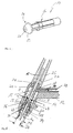
- the Fig. 1 and 2 shows a welding torch 10 with a arranged on a handle 11 burner head 12 having an electrode holder receptacle 13 in an electrode holder 14, which, in particular Fig. 2 shows, for receiving an electrode 15 is used.
- the electrode holder 14 on a receiving body 16 which is provided with a continuous longitudinal bore 17 in which a longitudinal portion 18 of the electrode 15 is received.
- a bore diameter D of the longitudinal bore 17 is slightly larger than a diameter d of the electrode 15.
- the receiving body 16 has in a clamping region 19, between a mounting portion 20 and a Front end 21 is formed, a longitudinal slot 22, so that in the clamping region 19, two clamping segments 29, 30 are formed.
- the receiving body 16 is provided in the clamping region 19 with an outer cone 23, which is preferably located in a central region of the longitudinal slot 22.
- Fig. 5 shows the electrode holder 14 accommodated in the electrode holder receptacle 13 of the welding torch 10 with the electrode 15 accommodated in the electrode holder 14.
- the electrode 15 inserted into the electrode holder 14 with the longitudinal section 18 together with the electrode holder 14 into a Receiving bore 24 of the arranged in the burner head 12 electrode holder receptacle 13 is inserted until the electrode holder 14 is supported with the outer cone 23 on a formed in the receiving bore 24 inner cone 25.
- a radial circumferential load clamping force distribution K is also in Fig. 5 indicated bending of defined by the longitudinal slot 22 clamping segments 29, 30 with formation of contact areas KB, in which the clamping segments 29, 30 abut against the electrode 15 and fix them in the electrode holder 14.
- the front end 21 is substantially conical in shape with a front surface 38 which has an annular end face 31, to which a clamping surface 19 conically widening lateral surface 32 connects.
- an outer diameter d F of the front surface 38 of the front end 21 in a transition region 33 to the clamping portion 19 formed larger than the outer diameter d K of the clamping portion 19.
- the outer diameter d F of the front end 21 is also formed larger as the bore diameter D B of the receiving bore 24 of the electrode holder receptacle 13.
- a distance a is formed between the front end 21 and the electrode holder receptacle 13.
- substantially as a cylindrical sleeve formed Schutzgasdüse 34 thus results in the formation of a protective gas ring channel 35 which is supplied to form a protective gas flow 39 via a formed in the burner head 12 shielding gas supply 39 with inert gas.
- a shielding cover of the receiving bore 24 of the electrode holder holder 13 is formed. This ensures that welding spatter or the like can not get into an annular channel section 36 formed between the clamping region 19 of the receiving body 16 and the receiving bore 24 of the electrode holder receptacle 13.
- the longitudinal slot 22 is axially closed, so that no spatter or the like can get into the longitudinal slot 22 and between the clamping segments 29, 30.
Landscapes
- Engineering & Computer Science (AREA)
- Physics & Mathematics (AREA)
- Plasma & Fusion (AREA)
- Mechanical Engineering (AREA)
- Arc Welding In General (AREA)
Description
- Die vorliegende Erfindung betrifft einen Elektrodenhalter für einen Schweißbrenner mit nicht abschmelzender Elektrode mit einem mit einer Längsbohrung zur Aufnahme eines Längsabschnitts einer Elektrode versehenen Aufnahmekörper, wobei der Aufnahmekörper in einem Klemmbereich mit einem Längsschlitz zur Ausbildung von Klemmsegmenten versehen ist und in einem an den Klemmbereich anschließenden Befestigungsbereich eine Verbindungseinrichtung zur Verbindung mit einer an einem Brennerkopf angeordneten Spanneinrichtung aufweist, wobei der Klemmbereich einen Außenkonus aufweist, der bei Anordnung des Elektrodenhalters in einer im Brennerkopf aufgenommenen Elektrodenhalteraufnahme derart mit einem Innenkonus der Elektrodenhalteraufnahme zusammenwirkt, dass bei Herstellung einer Verbindung zwischen der Verbindungseinrichtung des Elektrodenhalters und der Spanneinrichtung durch axiale Verspannung des Innenkonus mit dem Außenkonus im Klemmbereich des Aufnahmekörpers eine radiale Klemmkraft auf die Elektrode wirkt, wobei sich der im Aufnahmekörper ausgebildete Längsschlitz über den Außenkonus hinaus bis zu einem Frontende des Aufnahmekörpers erstreckt. Darüber hinaus betrifft die Erfindung einen Schweißbrenner mit einem derartigen Elektrodenhalter.
- Aus der
DE 195 37 988 C1 , Basis für den Oberbegriff des Anspruchs 1 ist ein Schweißbrenner mit nicht abschmelzender Elektrode bekannt, der in einer Elektrodenhalteraufnahme einen Elektrodenhalter der eingangs genannten Art aufweist, der zur klemmenden Aufnahme einer auswechselbar aufgenommenen Elektrode dient. Zur fixierten Aufnahme und Übertragung des Schweißstroms in die Elektrode ist der Elektrodenhalter zumindest teilweise als Klemmhülse auszubilden, wobei die Klemmhülse zur Ausbildung von Klemmsegmenten einen Längsschlitz aufweist, der sich bis zu einem axialen Endquerschnitt der Klemmhülse hin erstreckt, an dem ein Außenkonus ausgebildet ist. Aufgrund dieser bis in den axialen Endquerschnitt der Klemmhülse auslaufenden Ausgestaltung des Längsschlitzes weisen die Klemmsegmente bei einer Verspannung des Außenkonus mit dem Innenkonus der Elektrodenhalteraufnahme ein Biegeverhalten wie ein einseitig eingespannter Biegeträger auf; also eine maximale Auslenkung an den axialen Enden mit einer entsprechend hohen Flächenpressung an den axialen Enden und Kontaktbereichen zwischen den Klemmsegmenten und der Oberfläche der Elektrode, die auf den Bereich der axialen Enden begrenzt sind. - Darüber hinaus weist der bekannte Elektrodenhalter aufgrund des sich bis zum axialen Ende des Aufnahmekörpers erstreckenden Längsschlitzes an seinem axialen Ende einen Stirnspalt auf, in den bei einem Schweißvorgang Schweißspritzer eindringen könnten, welche die Relativbeweglichkeit der Klemmsegmente des Klemmbereichs beeinträchtigen, wenn dem Frontende kein Gaslinsengehäuse axial vorgeordnet wäre, das mit einem Hülsenabschnitt das Frontende abschirmt.
- Der vorliegenden Erfindung liegt daher die Aufgabe zugrunde, einen Elektrodenhalter für einen Schweißbrenner vorzuschlagen, der so ausgestaltet ist, dass zum einen eine Vergrößerung der zwischen dem Klemmbereich der Elektrodenaufnahme und der Elektrode ausgebildeten Kontaktflächen ermöglicht wird, und zum anderen die Ausbildung eines Stirnspaltes vermieden wird.
- Diese Aufgabe wird durch einen Elektrodenhalter mit den Merkmalen des Anspruchs 1 gelöst.
- Erfindungsgemäß erstreckt sich der im Aufnahmekörper ausgebildete Längsschlitz über den Außenkonus hinaus bis zu einem Frontende des Aufnahmekörpers, wobei das Frontende eine vordere axiale Begrenzung des Längsschlitzes im Aufnahmekörper ausbildet, derart, dass ein axiales Ende des Längsschlitzes von einem axialen Ende des Aufnahmekörpers durch das Frontende beabstandet ist.
- Die Klemmsegmente des erfindungsgemäßen Elektrodenhalters weisen aufgrund des in der Länge durch das Frontende begrenzten Ausgestaltung des Längsschlitzes ein Biegeverhalten auf, das dem Biegeverhalten eines an beiden Enden eingespannten Biegebalken ähnelt, so dass die Biegelinie der Klemmsegmente im Bereich des Außenkonus eine vergleichsweise geringe Steigung aufweist mit einer daraus resultierenden geringeren Flächenpressung und vergleichsweise größerer zwischen den Klemmsegmenten und der Elektrode ausgebildeten Kontaktbereichen. Darüber hinaus ist bei dem erfindungsgemäßen Elektrodenhalter das axiale Ende des Längsschlitzes vom axialen Ende des Aufnahmekörpers durch das Frontende beabstandet. Damit wird durch den Längsschlitz im axialen Ende des Elektrodenhalters kein Spalt ausgebildet, in den Schweißspritzer eindringen könnten.
- Bei einer besonders bevorzugten Ausführungsform des Elektrodenhalters weist das Frontende des Aufnahmekörpers eine die Längsbohrung einrahmende Frontfläche auf, deren Außendurchmesser größer ist als ein Außendurchmesser des Klemmbereichs, so dass sich ein abschirmender Effekt auch für den an das Frontende anschließenden Längsschlitz einstellt.
- Wenn das Frontende kegelförmig ausgebildet ist mit einem sich von einem Öffnungsrand der Längsbohrung zum Klemmbereich hin vergrößernden Außendurchmesser, kann das Frontende zusätzlich zur Ausgestaltung eines profilierten Strömungskanals zwischen der Oberfläche des Frontendes und einer das Frontende umgebenden Schutzgasdüse des Schweißbrenners dienen.
- Besonders vorteilhaft zur Verhinderung von Ablagerungen oder Aufschweißungen auf dem Frontende erweist es sich, wenn eine Frontfläche des Frontendes ein vom Klemmbereich des Elektrodenhalters abweichendes Material aufweist, das hinsichtlich seiner Anlagerungen verhindernden Wirkung optimierbar ist.
- Vorzugsweise ist das abweichende Material durch eine auf das Frontende aufgebrachte Beschichtung ausgebildet. Auch kann das Frontende aus einem vom Klemmbereich abweichenden Material gebildet sein.
- Wenn das Frontende unabhängig vom Klemmbereich des Elektrodenhalters ausgebildet und mit diesem verbunden ist, kann das Frontende unabhängig vom Klemmbereich hergestellt und nachträglich mit diesem verbunden werden.
- Besonders vorteilhaft ist es auch, wenn das Frontende lösbar mit dem Klemmbereich des Elektrodenhalters verbunden ist, so dass das Frontende insbesondere in Abhängigkeit von dem gewählten Schweißverfahren austauschbar ist.
- In besonders vorteilhaften Ausführungsformen des Elektrodenhalters ist das Frontende aus einem keramischen Material oder einem Kohlstoffmaterial, insbesondere Graphit, gebildet.
- Der erfindungsgemäße Schweißbrenner weist die Merkmale des Anspruchs 10 auf.
- Bei einer besonders vorteilhaften Ausführungsform des Schweißbrenners ist zwischen einer an der Elektrodenhalteraufnahme des Schweißbrenners angeordneten Schutzgasdüse und dem Frontende des Elektrodenhalters ein Schutzgasringkanal zur Schutzgasführung ausgebildet, so dass neben dem vorteilhaften Effekt des Frontendes hinsichtlich der eingangs erörterten Vergrößerung der Kontaktbereiche zwischen den Klemmsegmenten des Klemmbereichs und der Elektrode sowie der abschirmenden Wirkung betreffend den Längsschlitz das Frontende auch die Ausbildung einer definierten Schutzgasführung ermöglicht.
- Besonders vorteilhaft lässt sich der Schweißbrenner einsetzen, wenn der Schweißbrenner zur Durchführung eines WIG-Schweißverfahrens dient. Eine weitere vorteilhafte Möglichkeit zur Verwendung des Schweißbrenners ergibt sich, wenn dieser zur Durchführung eines Plasmaschweißverfahrens dient.
- Nachfolgend wird eine bevorzugte Ausführungsform der Erfindung anhand der Zeichnungen näher erläutert.
- Es zeigen:
- Fig. 1:
- einen Schweißbrenner in isometrischer Darstellung;
- Fig. 2:
- den in
Fig. 1 dargestellten Schweißbrenner in einer Teilschnittdarstellung mit einem in einer Elektrodenhalteraufnahme angeordneten Elektrodenhalter; - Fig. 3:
- den in
Fig. 2 dargestellten Elektrodenhalter in Seitenansicht; - Fig. 4:
- den in
Fig. 2 dargestellten Elektrodenhalter in isometrischer Darstellung; - Fig. 5:
- eine vergrößerte Teilschnittdarstellung des in
Fig. 2 dargestellten Schweißbrenners. - Die
Fig. 1 und 2 zeigt einen Schweißbrenner 10 mit einem an einem Handgriff 11 angeordneten Brennerkopf 12, der in einer Elektrodenhalteraufnahme 13 einen Elektrodenhalter 14 aufweist, der, wie insbesondereFig. 2 zeigt, zur Aufnahme einer Elektrode 15 dient. - Wie aus den
Fig. 2, 3 ,4 und 5 ersichtlich, weist der Elektrodenhalter 14 einen Aufnahmekörper 16 auf, der mit einer durchgehenden Längsbohrung 17 versehen ist, in der ein Längsabschnitt 18 der Elektrode 15 aufgenommen ist. Wie insbesondereFig. 3 zeigt, in die mit strichpunktiertem Linienverlauf der Längsabschnitt 18 der Elektrode 15 eingezeichnet ist, ist ein Bohrungsdurchmesser D der Längsbohrung 17 geringfügig größer ausgebildet als ein Durchmesser d der Elektrode 15. Der Aufnahmekörper 16 weist in einem Klemmbereich 19, der zwischen einem Befestigungsbereich 20 und einem Frontende 21 ausgebildet ist, einen Längsschlitz 22 auf, so dass im Klemmbereich 19 zwei Klemmsegmente 29, 30 ausgebildet werden. Weiterhin ist der Aufnahmekörper 16 im Klemmbereich 19 mit einem Außenkonus 23 versehen, der sich vorzugsweise in einem mittleren Bereich des Längsschlitzes 22 befindet. -
Fig. 5 zeigt den in der Elektrodenhalteraufnahme 13 des Schweißbrenners 10 aufgenommenen Elektrodenhalter 14 mit der im Elektrodenhalter 14 aufgenommenen Elektrode 15. Zur fixierten Aufnahme der Elektrode 15 im Elektrodenhalter 14 wird die in den Elektrodenhalter 14 mit dem Längsabschnitt 18 eingesetzte Elektrode 15 zusammen mit dem Elektrodenhalter 14 in eine Aufnahmebohrung 24 der im Brennerkopf 12 angeordneten Elektrodenhalteraufnahme 13 eingeführt, bis sich die Elektrodenaufnahme 14 mit dem Außenkonus 23 an einem in der Aufnahmebohrung 24 ausgebildeten Innenkonus 25 abstützt. - Anschließend wird eine als Brennerkappe 26 ausgeführte Spannvorrichtung, welche sich mit einem axialen Ende am Brennerkopf 12 abstützt, mit einer am axialen Ende angeordneten Spannmutter 27 auf einen im Befestigungsbereich 20 des Aufnahmekörpers 16 ausgebildeten Gewindezapfen 28 aufgeschraubt, derart, dass der Außenkonus 23 des Aufnahmekörpers 16 des Elektrodenhalters 14 in den Innenkonus 25 eingezogen wird und eine axiale Verspannung des Innenkonus 25 mit dem Außenkonus 23 im Klemmbereich 19 des Aufnahmekörpers 16 eine in
Fig. 5 angedeutete radiale Klemmkraftverteilung K bewirkt. Infolge der als radiale Umfangslast wirkenden Klemmkraftverteilung K erfolgt eine ebenfalls inFig. 5 angedeutete Biegung der durch den Längsschlitz 22 definierten Klemmsegmente 29, 30 mit Ausbildung von Kontaktbereichen KB, in denen die Klemmsegmente 29, 30 gegen die Elektrode 15 anliegen und diese in dem Elektrodenhalter 14 fixieren. - Aufgrund der Tatsache, dass der Längsschlitz 22 beidseitig axial begrenzt ist, nämlich zum einen durch den Verbindungsbereich 20 des Aufnahmekörpers 16 und zum anderen durch das Frontende 21 des Aufnahmekörpers 16, weisen die Klemmsegmente 29, 30 ein Biegeverhalten auf, das dem Biegefall eines beidseitig eingespannten Balkens entspricht. Hieraus resultieren die in
Fig. 5 schematisch angedeuteten Biegelinien B der Klemmsegmente 29, 30, die im Bereich des Außenkonus 23 eine nur geringe Steigung aufweisen, so dass sich die Klemmsegmente 29, 30 in den Klemmbereichen KB flächig an die Oberfläche der Elektrode 15 anschmiegen. - Wie die
Fig. 3 und4 zeigen, ist das Frontende 21 im Wesentlichen kegelförmig ausgebildet mit einer Frontfläche 38, die eine ringförmige Stirnfläche 31 aufweist, an die sich eine zum Klemmbereich 19 hin konisch erweiternde Mantelfläche 32 anschließt. Wie insbesondere ausFig. 5 zu ersehen ist, ist ein Außendurchmesser dF der Frontfläche 38 des Frontendes 21 in einem Übergangsbereich 33 zum Klemmbereich 19 größer ausgebildet als der Außendurchmesser dK des Klemmbereichs 19. Darüber hinaus ist bei dem dargestellten Ausführungsbeispiel der Außendurchmesser dF des Frontendes 21 ebenfalls größer ausgebildet als der Bohrungsdurchmesser DB der Aufnahmebohrung 24 der Elektrodenhalteraufnahme 13. - Darüber hinaus ist zwischen dem Frontende 21 und der Elektrodenhalteraufnahme 13 ein Abstand a ausgebildet. In Kombination mit einer auf die Elektrodenhalteraufnahme 13 aufgesetzten, im Wesentlichen wie eine zylindrische Hülse ausgebildeten Schutzgasdüse 34 ergibt sich somit die Ausbildung eines Schutzgasringkanals 35, der zur Ausbildung einer Schutzgasströmung 39 über eine im Brennerkopf 12 ausgebildete Schutzgaszuführung 39 mit Schutzgas versorgt wird. Durch das Frontende 21 ist eine abschirmende Überdeckung der Aufnahmebohrung 24 der Elektrodenhalteraufnahme 13 ausgebildet. Damit ist sichergestellt, dass Schweißspritzer oder dergleichen nicht in einen zwischen dem Klemmbereich 19 des Aufnahmekörpers 16 und der Aufnahmebohrung 24 der Elektrodenhalteraufnahme 13 ausgebildeten Ringkanalabschnitt 36 gelangen können. Ferner ist auch sichergestellt, dass durch das Frontende 21, das benachbart einem Längsschlitzende 37 (
Fig. 3 ) des Längsschlitzes 22 angeordnet ist, der Längsschlitz 22 axial abgeschlossen ist, sodass auch keine Schweißspritzer oder dergleichen in den Längsschlitz 22 bzw. zwischen die Klemmsegmente 29, 30 gelangen können.
Claims (13)
- Elektrodenhalter (14) für einen Schweißbrenner mit nicht abschmelzender Elektrode mit einem mit einer Längsbohrung (17) zur Aufnahme eines Längsabschnitts (18) einer Elektrode (15) versehenen Aufnahmekörper (16), wobei der Aufnahmekörper in einem Klemmbereich (19) mit einem Längsschlitz (22) zur Ausbildung von Klemmsegmenten (29, 30) versehen ist und in einem an den Klemmbereich anschließenden Befestigungsbereich (20) eine Verbindungseinrichtung zur Verbindung mit einer an einem Brennerkopf (12) des Schweißbrenners angeordneten Spanneinrichtung aufweist, wobei der Klemmbereich einen Außenkonus (23) aufweist, der bei Anordnung des Elektrodenhalters in einer im Brennerkopf aufgenommenen Elektrodenhalteraufnahme (13) derart mit einem Innenkonus (25) der Elektrodenhalteraufnahme zusammenwirkt, dass bei Herstellung einer Verbindung zwischen der Verbindungseinrichtung des Elektrodenhalters (14) und der Spanneinrichtung durch axiale Verspannung des Innenkonus (25) mit dem Außenkonus im Klemmbereich des Aufnahmekörpers eine radiale Klemmkraft auf die Elektrode wirkt, wobei sich der im Aufnahmekörper ausgebildete Längsschlitz (22) über den Außenkonus hinaus bis zu einem Frontende (21) des Aufnahmekörpers (16) erstreckt,
dadurch gekennzeichnet,
dass das Frontende (21) eine vordere axiale Begrenzung des Längsschlitzes (16) im Aufnahmekörper (14) ausbildet, derart, dass ein axiales Ende des Längsschlitzes (16) von einem axialen Ende des Aufnahmekörpers (14) durch das Frontende (21) beabstandet ist. - Elektrodenhalter nach Anspruch 1,
dadurch gekennzeichnet,
dass das Frontende (21) eine die Längsbohrung (17) einrahmende Frontfläche (38) aufweist, deren Außendurchmesser größer ist als ein Außendurchmesser des Klemmbereichs. - Elektrodenhalter nach Anspruch 1 oder 2,
dadurch gekennzeichnet,
dass das Frontende (21) kegelförmig ausgebildet ist mit einem sich von einem Öffnungsrand der Längsbohrung (17) zum Klemmbereich (19) hin vergrößernden Außendurchmesser. - Elektrodenhalter nach Anspruch 2 oder 3,
dadurch gekennzeichnet,
dass die Frontfläche (38) ein vom Klemmbereich des Elektrodenhalters abweichendes Material aufweist. - Elektrodenhalter nach Anspruch 4,
dadurch gekennzeichnet,
dass die Frontfläche (38) des Elektrodenhalters eine auf das Frontende (21) aufgebrachte Beschichtung aufweist. - Elektrodenhalter nach einem der vorangehenden Ansprüche,
dadurch gekennzeichnet,
dass das Frontende (21) aus einem vom Klemmbereich (19) abweichenden Material gebildet ist. - Elektrodenhalter nach einem der vorangehenden Ansprüche,
dadurch gekennzeichnet,
dass das Frontende (21) unabhängig vom Klemmbereich (19) des Elektrodenhalters (14) ausgebildet und mit diesem verbunden ist. - Elektrodenhalter nach Anspruch 7,
dadurch gekennzeichnet,
dass das Frontende (21) lösbar mit dem Klemmbereich (19) des Elektrodenhalters (14) verbunden ist. - Elektrodenhalter nach einem der vorangehenden Ansprüche,
dadurch gekennzeichnet,
dass das Frontende (21) aus einem keramischen Material oder einem Kohlenstoffmaterial, insbesondere Graphit, gebildet ist. - Schweißbrenner (10) mit nicht abschmelzender Elektrode mit einem in einer Elektrodenhalteraufnahme des Schweißbrenners angeordneten Elektrodenhalter nach einem der Ansprüche 1 bis 9.
- Schweißbrenner (10) nach Anspruch 10,
dadurch gekennzeichnet,
dass zwischen einer an der Elektrodenhalteraufnahme (13) des Schweißbrenners angeordneten Schutzgasdüse (34) und dem Frontende (21) des Elektrodenhalters (14) ein Schutzgasringkanal (35) zur Schutzgasführung ausgebildet ist. - Schweißbrenner nach Anspruch 10 oder 11,
dadurch gekennzeichnet,
dass der Schweißbrenner zur Durchführung eines WIG-Schweißverfahrens dient. - Schweißbrenner nach Anspruch 10 oder 11,
dadurch gekennzeichnet,
dass der Schweißbrenner zur Durchführung eines Plasma-Schweißverfahrens dient.
Applications Claiming Priority (1)
| Application Number | Priority Date | Filing Date | Title |
|---|---|---|---|
| DE102013014817 | 2013-09-10 |
Publications (2)
| Publication Number | Publication Date |
|---|---|
| EP2857136A1 EP2857136A1 (de) | 2015-04-08 |
| EP2857136B1 true EP2857136B1 (de) | 2016-11-09 |
Family
ID=51627940
Family Applications (1)
| Application Number | Title | Priority Date | Filing Date |
|---|---|---|---|
| EP14184261.7A Active EP2857136B1 (de) | 2013-09-10 | 2014-09-10 | Elektrodenhalter für einen Schweißbrenner sowie entsprechender Schweißbrenner |
Country Status (1)
| Country | Link |
|---|---|
| EP (1) | EP2857136B1 (de) |
Families Citing this family (2)
| Publication number | Priority date | Publication date | Assignee | Title |
|---|---|---|---|---|
| US12240065B2 (en) | 2016-06-15 | 2025-03-04 | Jinan Uniarc Welding Technology Limited | TIG welding torch |
| PL3581316T3 (pl) | 2016-06-15 | 2024-12-23 | Jinan Uniarc Welding Technology Limited | Palnik do spawania tig |
Family Cites Families (4)
| Publication number | Priority date | Publication date | Assignee | Title |
|---|---|---|---|---|
| US2527235A (en) * | 1949-06-24 | 1950-10-24 | Gen Electric | Fluid cooled welding apparatus |
| JP2677763B2 (ja) * | 1993-04-13 | 1997-11-17 | アレクサンダー ビンツェル ゲゼルシャフト ミット ベシュレンクテル ハフツング ウント コンパニー コマンディートゲゼルシャフト | アーク溶接又はアーク切断用のトーチ |
| DE19537988C1 (de) * | 1995-05-05 | 1996-10-31 | Binzel Alexander Gmbh Co Kg | Gaslinsengehäuse für Lichtbogenschweiß- oder -schneidbrenner mit nicht abschmelzender Elektrode |
| EP2295185A2 (de) * | 2009-09-10 | 2011-03-16 | TBI Industries GmbH | Elektrodenkartusche und Verfahren zur Befestigung einer Elektrode an einem Schweißbrenner |
-
2014
- 2014-09-10 EP EP14184261.7A patent/EP2857136B1/de active Active
Also Published As
| Publication number | Publication date |
|---|---|
| EP2857136A1 (de) | 2015-04-08 |
Similar Documents
| Publication | Publication Date | Title |
|---|---|---|
| DE1275499B (de) | Schraemmeissel od. dgl. Werkzeug mit einer eingesetzten zapfenartigen Hartmetallspitze | |
| DE112015000350T5 (de) | Schweissbrennerbaugruppe und -Komponenten erhöhter Widerstandsfähigkeit | |
| DE102007036289A1 (de) | Verfahren und eine Vorrichtung zum Schweißen von Rundnähten | |
| EP3017901B1 (de) | Wig-schweissbrenner mit kreisbogenförmiger führung | |
| EP1039982B1 (de) | Schweissbrenner | |
| EP2857136A1 (de) | Elektrodenhalter für einen Schweißbrenner sowie entsprechender Schweißbrenner | |
| DE2920917C3 (de) | Schutzgasschweißbrenner | |
| DE102005049010A1 (de) | Verfahren zum Schneiden von Werkstücken mit einem Laserstrahl | |
| AT506485B1 (de) | Schutzgasschweissbrenner | |
| DE3841325A1 (de) | Als flachduese ausgebildete schutzgasduese fuer schutzgasschweissbrenner | |
| EP3663029B1 (de) | Elektrodeneinheit für inertgasschweissen mit nicht abschmelzender elektrode | |
| EP2487003B1 (de) | Schweißpistole eines Lichtbogenschweißgerätes | |
| DE102012111460B4 (de) | Schweißstromdüse | |
| DE102023004143B4 (de) | Verfahren zum Fügen von Bauteilen durch Laserschweißen mittels einer Laserschweißvorrichtung | |
| DE102015013847A1 (de) | Laserschweißeinrichtung | |
| DE102020132821A1 (de) | Brennerhals zum thermischen Fügen wenigstens eines Werkstücks, Brenner mit Brennerhals und Schweißvorrichtung | |
| AT12972U1 (de) | Schweissbrenner und verbindungselement für einen schweissbrenner | |
| WO2009030431A2 (de) | Laserbearbeitungskopf zur bearbeitung eines werkstücks mittels eines laserstrahls mit lösbar verbundenem gehäuse, aufnahmevorrichtung und düse; düsenelement mit einem verrundeten verjüngungsbereich; aufnahmevorrichtung | |
| DE9216866U1 (de) | Schutzgas-Handschweißbrenner | |
| DE4313830C2 (de) | Aufsatz für einen Lichtbogenschweiß- oder -schneidbrenner mit einem zylindrischen Fortsatz | |
| DE19831816A1 (de) | Verbesserter Plasmabrenner | |
| DE102013214551B4 (de) | Drahtdüse und Verfahren zum Laserfügen mit Zusatzdraht mit taktiler Drahtführung | |
| EP4512564A2 (de) | Verschleisselektrode zum widerstandsbuckelschweissen von bolzen | |
| DE8324959U1 (de) | Stromdüse für Schweißpistolen | |
| DE202008017540U1 (de) | Strömungsdüse für ein Schweißgerät |
Legal Events
| Date | Code | Title | Description |
|---|---|---|---|
| PUAI | Public reference made under article 153(3) epc to a published international application that has entered the european phase |
Free format text: ORIGINAL CODE: 0009012 |
|
| 17P | Request for examination filed |
Effective date: 20140910 |
|
| AK | Designated contracting states |
Kind code of ref document: A1 Designated state(s): AL AT BE BG CH CY CZ DE DK EE ES FI FR GB GR HR HU IE IS IT LI LT LU LV MC MK MT NL NO PL PT RO RS SE SI SK SM TR |
|
| AX | Request for extension of the european patent |
Extension state: BA ME |
|
| R17P | Request for examination filed (corrected) |
Effective date: 20151006 |
|
| RBV | Designated contracting states (corrected) |
Designated state(s): AL AT BE BG CH CY CZ DE DK EE ES FI FR GB GR HR HU IE IS IT LI LT LU LV MC MK MT NL NO PL PT RO RS SE SI SK SM TR |
|
| GRAP | Despatch of communication of intention to grant a patent |
Free format text: ORIGINAL CODE: EPIDOSNIGR1 |
|
| RIC1 | Information provided on ipc code assigned before grant |
Ipc: B23K 9/28 20060101ALI20160307BHEP Ipc: B23K 9/29 20060101ALI20160307BHEP Ipc: B23K 9/167 20060101AFI20160307BHEP |
|
| INTG | Intention to grant announced |
Effective date: 20160329 |
|
| GRAS | Grant fee paid |
Free format text: ORIGINAL CODE: EPIDOSNIGR3 |
|
| GRAA | (expected) grant |
Free format text: ORIGINAL CODE: 0009210 |
|
| AK | Designated contracting states |
Kind code of ref document: B1 Designated state(s): AL AT BE BG CH CY CZ DE DK EE ES FI FR GB GR HR HU IE IS IT LI LT LU LV MC MK MT NL NO PL PT RO RS SE SI SK SM TR |
|
| REG | Reference to a national code |
Ref country code: GB Ref legal event code: FG4D Free format text: NOT ENGLISH |
|
| REG | Reference to a national code |
Ref country code: AT Ref legal event code: REF Ref document number: 843426 Country of ref document: AT Kind code of ref document: T Effective date: 20161115 Ref country code: CH Ref legal event code: EP |
|
| REG | Reference to a national code |
Ref country code: IE Ref legal event code: FG4D Free format text: LANGUAGE OF EP DOCUMENT: GERMAN |
|
| REG | Reference to a national code |
Ref country code: DE Ref legal event code: R096 Ref document number: 502014001905 Country of ref document: DE |
|
| REG | Reference to a national code |
Ref country code: NL Ref legal event code: FP |
|
| PG25 | Lapsed in a contracting state [announced via postgrant information from national office to epo] |
Ref country code: LV Free format text: LAPSE BECAUSE OF FAILURE TO SUBMIT A TRANSLATION OF THE DESCRIPTION OR TO PAY THE FEE WITHIN THE PRESCRIBED TIME-LIMIT Effective date: 20161109 |
|
| REG | Reference to a national code |
Ref country code: LT Ref legal event code: MG4D |
|
| PG25 | Lapsed in a contracting state [announced via postgrant information from national office to epo] |
Ref country code: GR Free format text: LAPSE BECAUSE OF FAILURE TO SUBMIT A TRANSLATION OF THE DESCRIPTION OR TO PAY THE FEE WITHIN THE PRESCRIBED TIME-LIMIT Effective date: 20170210 Ref country code: SE Free format text: LAPSE BECAUSE OF FAILURE TO SUBMIT A TRANSLATION OF THE DESCRIPTION OR TO PAY THE FEE WITHIN THE PRESCRIBED TIME-LIMIT Effective date: 20161109 Ref country code: NO Free format text: LAPSE BECAUSE OF FAILURE TO SUBMIT A TRANSLATION OF THE DESCRIPTION OR TO PAY THE FEE WITHIN THE PRESCRIBED TIME-LIMIT Effective date: 20170209 Ref country code: LT Free format text: LAPSE BECAUSE OF FAILURE TO SUBMIT A TRANSLATION OF THE DESCRIPTION OR TO PAY THE FEE WITHIN THE PRESCRIBED TIME-LIMIT Effective date: 20161109 |
|
| PG25 | Lapsed in a contracting state [announced via postgrant information from national office to epo] |
Ref country code: FI Free format text: LAPSE BECAUSE OF FAILURE TO SUBMIT A TRANSLATION OF THE DESCRIPTION OR TO PAY THE FEE WITHIN THE PRESCRIBED TIME-LIMIT Effective date: 20161109 Ref country code: PL Free format text: LAPSE BECAUSE OF FAILURE TO SUBMIT A TRANSLATION OF THE DESCRIPTION OR TO PAY THE FEE WITHIN THE PRESCRIBED TIME-LIMIT Effective date: 20161109 Ref country code: IS Free format text: LAPSE BECAUSE OF FAILURE TO SUBMIT A TRANSLATION OF THE DESCRIPTION OR TO PAY THE FEE WITHIN THE PRESCRIBED TIME-LIMIT Effective date: 20170309 Ref country code: HR Free format text: LAPSE BECAUSE OF FAILURE TO SUBMIT A TRANSLATION OF THE DESCRIPTION OR TO PAY THE FEE WITHIN THE PRESCRIBED TIME-LIMIT Effective date: 20161109 Ref country code: PT Free format text: LAPSE BECAUSE OF FAILURE TO SUBMIT A TRANSLATION OF THE DESCRIPTION OR TO PAY THE FEE WITHIN THE PRESCRIBED TIME-LIMIT Effective date: 20170309 Ref country code: RS Free format text: LAPSE BECAUSE OF FAILURE TO SUBMIT A TRANSLATION OF THE DESCRIPTION OR TO PAY THE FEE WITHIN THE PRESCRIBED TIME-LIMIT Effective date: 20161109 Ref country code: ES Free format text: LAPSE BECAUSE OF FAILURE TO SUBMIT A TRANSLATION OF THE DESCRIPTION OR TO PAY THE FEE WITHIN THE PRESCRIBED TIME-LIMIT Effective date: 20161109 |
|
| PG25 | Lapsed in a contracting state [announced via postgrant information from national office to epo] |
Ref country code: DK Free format text: LAPSE BECAUSE OF FAILURE TO SUBMIT A TRANSLATION OF THE DESCRIPTION OR TO PAY THE FEE WITHIN THE PRESCRIBED TIME-LIMIT Effective date: 20161109 Ref country code: SK Free format text: LAPSE BECAUSE OF FAILURE TO SUBMIT A TRANSLATION OF THE DESCRIPTION OR TO PAY THE FEE WITHIN THE PRESCRIBED TIME-LIMIT Effective date: 20161109 Ref country code: EE Free format text: LAPSE BECAUSE OF FAILURE TO SUBMIT A TRANSLATION OF THE DESCRIPTION OR TO PAY THE FEE WITHIN THE PRESCRIBED TIME-LIMIT Effective date: 20161109 Ref country code: RO Free format text: LAPSE BECAUSE OF FAILURE TO SUBMIT A TRANSLATION OF THE DESCRIPTION OR TO PAY THE FEE WITHIN THE PRESCRIBED TIME-LIMIT Effective date: 20161109 Ref country code: CZ Free format text: LAPSE BECAUSE OF FAILURE TO SUBMIT A TRANSLATION OF THE DESCRIPTION OR TO PAY THE FEE WITHIN THE PRESCRIBED TIME-LIMIT Effective date: 20161109 |
|
| REG | Reference to a national code |
Ref country code: DE Ref legal event code: R097 Ref document number: 502014001905 Country of ref document: DE |
|
| PG25 | Lapsed in a contracting state [announced via postgrant information from national office to epo] |
Ref country code: BG Free format text: LAPSE BECAUSE OF FAILURE TO SUBMIT A TRANSLATION OF THE DESCRIPTION OR TO PAY THE FEE WITHIN THE PRESCRIBED TIME-LIMIT Effective date: 20170209 Ref country code: SM Free format text: LAPSE BECAUSE OF FAILURE TO SUBMIT A TRANSLATION OF THE DESCRIPTION OR TO PAY THE FEE WITHIN THE PRESCRIBED TIME-LIMIT Effective date: 20161109 |
|
| PLBE | No opposition filed within time limit |
Free format text: ORIGINAL CODE: 0009261 |
|
| STAA | Information on the status of an ep patent application or granted ep patent |
Free format text: STATUS: NO OPPOSITION FILED WITHIN TIME LIMIT |
|
| REG | Reference to a national code |
Ref country code: FR Ref legal event code: PLFP Year of fee payment: 4 |
|
| 26N | No opposition filed |
Effective date: 20170810 |
|
| PG25 | Lapsed in a contracting state [announced via postgrant information from national office to epo] |
Ref country code: SI Free format text: LAPSE BECAUSE OF FAILURE TO SUBMIT A TRANSLATION OF THE DESCRIPTION OR TO PAY THE FEE WITHIN THE PRESCRIBED TIME-LIMIT Effective date: 20161109 |
|
| REG | Reference to a national code |
Ref country code: CH Ref legal event code: PL |
|
| PG25 | Lapsed in a contracting state [announced via postgrant information from national office to epo] |
Ref country code: MC Free format text: LAPSE BECAUSE OF FAILURE TO SUBMIT A TRANSLATION OF THE DESCRIPTION OR TO PAY THE FEE WITHIN THE PRESCRIBED TIME-LIMIT Effective date: 20161109 |
|
| REG | Reference to a national code |
Ref country code: IE Ref legal event code: MM4A |
|
| REG | Reference to a national code |
Ref country code: BE Ref legal event code: MM Effective date: 20170930 |
|
| PG25 | Lapsed in a contracting state [announced via postgrant information from national office to epo] |
Ref country code: LU Free format text: LAPSE BECAUSE OF NON-PAYMENT OF DUE FEES Effective date: 20170910 |
|
| PG25 | Lapsed in a contracting state [announced via postgrant information from national office to epo] |
Ref country code: LI Free format text: LAPSE BECAUSE OF NON-PAYMENT OF DUE FEES Effective date: 20170930 Ref country code: IE Free format text: LAPSE BECAUSE OF NON-PAYMENT OF DUE FEES Effective date: 20170910 Ref country code: CH Free format text: LAPSE BECAUSE OF NON-PAYMENT OF DUE FEES Effective date: 20170930 |
|
| PG25 | Lapsed in a contracting state [announced via postgrant information from national office to epo] |
Ref country code: BE Free format text: LAPSE BECAUSE OF NON-PAYMENT OF DUE FEES Effective date: 20170930 |
|
| REG | Reference to a national code |
Ref country code: FR Ref legal event code: PLFP Year of fee payment: 5 |
|
| PG25 | Lapsed in a contracting state [announced via postgrant information from national office to epo] |
Ref country code: MT Free format text: LAPSE BECAUSE OF FAILURE TO SUBMIT A TRANSLATION OF THE DESCRIPTION OR TO PAY THE FEE WITHIN THE PRESCRIBED TIME-LIMIT Effective date: 20161109 |
|
| PG25 | Lapsed in a contracting state [announced via postgrant information from national office to epo] |
Ref country code: HU Free format text: LAPSE BECAUSE OF FAILURE TO SUBMIT A TRANSLATION OF THE DESCRIPTION OR TO PAY THE FEE WITHIN THE PRESCRIBED TIME-LIMIT; INVALID AB INITIO Effective date: 20140910 |
|
| PG25 | Lapsed in a contracting state [announced via postgrant information from national office to epo] |
Ref country code: CY Free format text: LAPSE BECAUSE OF FAILURE TO SUBMIT A TRANSLATION OF THE DESCRIPTION OR TO PAY THE FEE WITHIN THE PRESCRIBED TIME-LIMIT Effective date: 20161109 |
|
| PG25 | Lapsed in a contracting state [announced via postgrant information from national office to epo] |
Ref country code: MK Free format text: LAPSE BECAUSE OF FAILURE TO SUBMIT A TRANSLATION OF THE DESCRIPTION OR TO PAY THE FEE WITHIN THE PRESCRIBED TIME-LIMIT Effective date: 20161109 |
|
| PG25 | Lapsed in a contracting state [announced via postgrant information from national office to epo] |
Ref country code: TR Free format text: LAPSE BECAUSE OF FAILURE TO SUBMIT A TRANSLATION OF THE DESCRIPTION OR TO PAY THE FEE WITHIN THE PRESCRIBED TIME-LIMIT Effective date: 20161109 |
|
| PG25 | Lapsed in a contracting state [announced via postgrant information from national office to epo] |
Ref country code: AL Free format text: LAPSE BECAUSE OF FAILURE TO SUBMIT A TRANSLATION OF THE DESCRIPTION OR TO PAY THE FEE WITHIN THE PRESCRIBED TIME-LIMIT Effective date: 20161109 |
|
| P01 | Opt-out of the competence of the unified patent court (upc) registered |
Effective date: 20230522 |
|
| PGFP | Annual fee paid to national office [announced via postgrant information from national office to epo] |
Ref country code: DE Payment date: 20250929 Year of fee payment: 12 |
|
| PGFP | Annual fee paid to national office [announced via postgrant information from national office to epo] |
Ref country code: NL Payment date: 20250926 Year of fee payment: 12 Ref country code: IT Payment date: 20250919 Year of fee payment: 12 |
|
| PGFP | Annual fee paid to national office [announced via postgrant information from national office to epo] |
Ref country code: GB Payment date: 20250929 Year of fee payment: 12 |
|
| PGFP | Annual fee paid to national office [announced via postgrant information from national office to epo] |
Ref country code: FR Payment date: 20250925 Year of fee payment: 12 Ref country code: AT Payment date: 20250929 Year of fee payment: 12 |