EP2856550B1 - Verteilerablauf für einen brennstoffzellengaseinlass - Google Patents
Verteilerablauf für einen brennstoffzellengaseinlass Download PDFInfo
- Publication number
- EP2856550B1 EP2856550B1 EP12877177.1A EP12877177A EP2856550B1 EP 2856550 B1 EP2856550 B1 EP 2856550B1 EP 12877177 A EP12877177 A EP 12877177A EP 2856550 B1 EP2856550 B1 EP 2856550B1
- Authority
- EP
- European Patent Office
- Prior art keywords
- drain channel
- manifold
- gas
- inlet manifold
- gas inlet
- Prior art date
- Legal status (The legal status is an assumption and is not a legal conclusion. Google has not performed a legal analysis and makes no representation as to the accuracy of the status listed.)
- Active
Links
Images
Classifications
-
- H—ELECTRICITY
- H01—ELECTRIC ELEMENTS
- H01M—PROCESSES OR MEANS, e.g. BATTERIES, FOR THE DIRECT CONVERSION OF CHEMICAL ENERGY INTO ELECTRICAL ENERGY
- H01M8/00—Fuel cells; Manufacture thereof
- H01M8/04—Auxiliary arrangements, e.g. for control of pressure or for circulation of fluids
- H01M8/04082—Arrangements for control of reactant parameters, e.g. pressure or concentration
- H01M8/04089—Arrangements for control of reactant parameters, e.g. pressure or concentration of gaseous reactants
- H01M8/04119—Arrangements for control of reactant parameters, e.g. pressure or concentration of gaseous reactants with simultaneous supply or evacuation of electrolyte; Humidifying or dehumidifying
- H01M8/04156—Arrangements for control of reactant parameters, e.g. pressure or concentration of gaseous reactants with simultaneous supply or evacuation of electrolyte; Humidifying or dehumidifying with product water removal
-
- H—ELECTRICITY
- H01—ELECTRIC ELEMENTS
- H01M—PROCESSES OR MEANS, e.g. BATTERIES, FOR THE DIRECT CONVERSION OF CHEMICAL ENERGY INTO ELECTRICAL ENERGY
- H01M8/00—Fuel cells; Manufacture thereof
- H01M8/24—Grouping of fuel cells, e.g. stacking of fuel cells
-
- H—ELECTRICITY
- H01—ELECTRIC ELEMENTS
- H01M—PROCESSES OR MEANS, e.g. BATTERIES, FOR THE DIRECT CONVERSION OF CHEMICAL ENERGY INTO ELECTRICAL ENERGY
- H01M8/00—Fuel cells; Manufacture thereof
- H01M8/02—Details
-
- H—ELECTRICITY
- H01—ELECTRIC ELEMENTS
- H01M—PROCESSES OR MEANS, e.g. BATTERIES, FOR THE DIRECT CONVERSION OF CHEMICAL ENERGY INTO ELECTRICAL ENERGY
- H01M8/00—Fuel cells; Manufacture thereof
- H01M8/02—Details
- H01M8/0271—Sealing or supporting means around electrodes, matrices or membranes
-
- H—ELECTRICITY
- H01—ELECTRIC ELEMENTS
- H01M—PROCESSES OR MEANS, e.g. BATTERIES, FOR THE DIRECT CONVERSION OF CHEMICAL ENERGY INTO ELECTRICAL ENERGY
- H01M8/00—Fuel cells; Manufacture thereof
- H01M8/04—Auxiliary arrangements, e.g. for control of pressure or for circulation of fluids
-
- H—ELECTRICITY
- H01—ELECTRIC ELEMENTS
- H01M—PROCESSES OR MEANS, e.g. BATTERIES, FOR THE DIRECT CONVERSION OF CHEMICAL ENERGY INTO ELECTRICAL ENERGY
- H01M8/00—Fuel cells; Manufacture thereof
- H01M8/04—Auxiliary arrangements, e.g. for control of pressure or for circulation of fluids
- H01M8/04082—Arrangements for control of reactant parameters, e.g. pressure or concentration
- H01M8/04201—Reactant storage and supply, e.g. means for feeding, pipes
-
- H—ELECTRICITY
- H01—ELECTRIC ELEMENTS
- H01M—PROCESSES OR MEANS, e.g. BATTERIES, FOR THE DIRECT CONVERSION OF CHEMICAL ENERGY INTO ELECTRICAL ENERGY
- H01M8/00—Fuel cells; Manufacture thereof
- H01M8/24—Grouping of fuel cells, e.g. stacking of fuel cells
- H01M8/2465—Details of groupings of fuel cells
- H01M8/2484—Details of groupings of fuel cells characterised by external manifolds
- H01M8/2485—Arrangements for sealing external manifolds; Arrangements for mounting external manifolds around a stack
-
- Y—GENERAL TAGGING OF NEW TECHNOLOGICAL DEVELOPMENTS; GENERAL TAGGING OF CROSS-SECTIONAL TECHNOLOGIES SPANNING OVER SEVERAL SECTIONS OF THE IPC; TECHNICAL SUBJECTS COVERED BY FORMER USPC CROSS-REFERENCE ART COLLECTIONS [XRACs] AND DIGESTS
- Y02—TECHNOLOGIES OR APPLICATIONS FOR MITIGATION OR ADAPTATION AGAINST CLIMATE CHANGE
- Y02E—REDUCTION OF GREENHOUSE GAS [GHG] EMISSIONS, RELATED TO ENERGY GENERATION, TRANSMISSION OR DISTRIBUTION
- Y02E60/00—Enabling technologies; Technologies with a potential or indirect contribution to GHG emissions mitigation
- Y02E60/30—Hydrogen technology
- Y02E60/50—Fuel cells
Definitions
- Fuel cells utilize an electrochemical reaction for generating electricity.
- the electrochemical reaction involves reactants such as hydrogen and oxygen.
- Air is typically used as the source of oxygen.
- Introducing air to a cell stack assembly often introduces moisture because of the humidity of the air.
- US 2012/107704A1 discloses a temperature-sensitive bypass device for discharging condensed water from a fuel cell stack, the device comprising a bypass line configured for discharging condensed water, provided between an end plate and a separator located at an outermost cell adjacent to an inlet of the fuel cell stack.
- the bypass line may extend from a reactant gas inlet manifold of the end plate to a reactant gas outlet manifold of the end plate.
- a temperature-sensitive valve is provided in the bypass line, the opening and closing of which depends on the temperature of the fuel cell stack.
- Subject-matter of this invention is a manifold assembly as claimed in claim 1, a fuel cell as claimed in claim 3, and a fluid management method as claimed in claim 4.
- Preferred embodiments of this invention are claimed in the dependent claims.
- a manifold assembly includes a gas inlet manifold configured to introduce a gas to a fuel cell.
- a gas outlet manifold is configured to direct gas away from the fuel cell.
- a drain channel connects the inlet manifold to the outlet manifold. The drain channel is configured to carry liquid from the gas inlet manifold to the gas outlet manifold.
- the drain channel allows for removing condensate liquid from the gas inlet manifold to prevent such liquid from interfering with the intended supply of the gas to the fuel cell.
- a fuel cell according to this invention includes a stack cell assembly having a plurality of cells that are configured to facilitate an electrochemical reaction.
- a gas inlet manifold is on one side of the cell stack assembly.
- the gas inlet manifold is configured to introduce a gas to the cell stack assembly.
- a gas outlet manifold is on another side of the cell stack assembly.
- the gas outlet manifold is configured to direct gas away from the cell stack assembly.
- a drain channel connects the gas inlet manifold to the gas outlet manifold.
- the drain channel is configured to carry liquid from the inlet manifold to the outlet manifold.
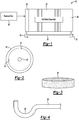
- FIG. 1 schematically shows a fuel cell device 20.
- a cell stack assembly 22 includes a plurality of individual cells that are configured to facilitate an electrochemical reaction.
- Example cells may comprise PEM fuel cells or phosphoric acid fuel cells. Those skilled in the art understand how cell stack assemblies are arranged.
- a gas inlet manifold 24 is provided on one side of the cell stack assembly 22.
- the gas inlet manifold 24 facilitates introducing a reactant gas 26 to the cell stack assembly 22.
- the reactant gas 26 comprises air for introducing oxygen into the cell stack assembly 22.
- Oxygen is used in an electrochemical reaction within a fuel cell in a known manner.
- the example of Figure 1 includes a gas outlet manifold 28 on another side of the cell stack assembly 22.
- the gas inlet manifold 24 is on an opposite side of the cell stack assembly from the gas outlet manifold 28 but that is not the only possible arrangement.
- Various positions of the manifolds 24 and 28 are possible.
- Using air for introducing the reactant gas 26 includes the possibility of liquid condensation within the gas inlet manifold 24.
- Air typically has some amount of humidity or moisture within it. Any moisture entrained in the gas provided to the gas inlet manifold 24 may condense on an inside surface of the gas inlet manifold 24. Such condensation may occur because of differences in temperature, for example, between the walls of the manifold 24 and the air that is introduced into the manifold 24.
- a drain channel 30 is connected between the gas inlet manifold 24 and the gas outlet manifold 28.
- the drain channel 30 comprises a tube.
- the drain channel 30 facilitates removing any liquid condensation from the gas inlet manifold 24 as such liquid is allowed to flow through the drain channel 30 as schematically shown by the arrows 32. Given that the gas outlet manifold 28 is already configured for directing fluid away from the cell stack assembly 22, the liquid from the drain channel 30 may be removed from the gas outlet manifold 28 and directed to another portion (not illustrated) of the fuel cell system.
- the drain channel 30 is connected with the gas inlet manifold 24 in a position (e.g., near a bottom or a lower end) where gravity facilitates movement of any liquid condensation into the drain channel 30.
- a gravitational pull may be useful for urging liquid into the drain channel and partially along that channel. In some configurations, gravitational pull will direct the liquid the entire way through the drain channel 30 and into the gas outlet manifold 28.
- the pressure differential across the cell stack assembly 22 is used at least partially for urging the liquid through the drain channel 30 and into the outlet manifold 28.
- the gas introduced into the gas inlet manifold 24 is intended to be provided to the cell stack assembly 22.
- a flow restrictor is associated with the drain channel 30 to restrict a flow of gas through the drain channel 30 while permitting liquid flow through that channel.
- the flow restrictor may be in the drain channel 30, at an interface between the drain channel 30 or across an opening in the manifold 24 to which the drain channel is connected.
- Figure 2 illustrates one example flow restrictor.
- This example comprises a diaphragm 40.
- An outside dimension 42 of the diaphragm 40 corresponds to an inside dimension of the drain channel 30 or an opening in the gas inlet manifold 24 to which the drain channel 30 is connected.
- the diaphragm includes an opening 44 that has a dimension that is much smaller than the outside dimension 42 of the diaphragm. The opening 44 allows at least liquid droplets to pass through from the gas inlet manifold 24 into the drain channel 30.
- FIG. 3 schematically illustrates another flow restrictor 50, which is a wet seal.
- the flow restrictor 50 comprises a porous plate or disk located within the drain channel 30, across an interface between the drain channel 30 and the gas inlet manifold 24 or over an opening in the gas inlet manifold 24 to which the drain channel 30 is connected
- the porous member 50 allows for liquid to pass through the flow restrictor 50.
- the porous member 50 is at least partially saturated (i.e., the pores are at least partially blocked by liquid), that limits or prevents gas flow through the porous member 50. Even when dry, the porous member 50 reduces possible gas flow through the drain channel 30. Preventing or limiting gas flow through the drain channel 30 facilitates having as much of the gas introduced into the manifold 24 supplied to the cell stack assembly 22 as possible.
- Figure 4 illustrates another example flow restrictor configuration.
- This example comprises a section 52 of the drain channel 30 that is configured to at least temporarily retain liquid. Liquid retained in the section 52 establishes a barrier across which gas from the gas inlet manifold 24 will not pass under many operating conditions.
- One limitation of the example of Figure 4 compared to the examples of Figures 2 and 3 is that it depends on the presence of at least some liquid within the section 52 of the drain channel 30 to restrict gas flow through the drain channel 30.
- a manifold assembly designed consistent with the disclosed examples provides the ability to manage liquid content within a gas inlet manifold of a fuel cell device.
Landscapes
- Life Sciences & Earth Sciences (AREA)
- Engineering & Computer Science (AREA)
- Manufacturing & Machinery (AREA)
- Sustainable Development (AREA)
- Sustainable Energy (AREA)
- Chemical & Material Sciences (AREA)
- Chemical Kinetics & Catalysis (AREA)
- Electrochemistry (AREA)
- General Chemical & Material Sciences (AREA)
- Fuel Cell (AREA)
Claims (5)
- Verteileraufbau, umfassendeinen Gaseinlassverteiler (24), konfiguriert um ein Gas (26) zu einer Brennstoffzelle einzuleiten;einen Gasauslassverteiler (28), konfiguriert um Gas weg von der Brennstoffzelle zu leiten; undeinen Entleerungskanal (30), das den Einlassverteiler (24) zu dem Auslassverteiler (28) verbindet, wobei der Entleerungskanal (30) konfiguriert ist, um Flüssigkeit von dem Gaseinlassverteiler (24) zu dem Gasauslassverteiler (28) zu bringen,wobei der Gaseinlassverteiler (24) ein oberes Ende und ein unteres Ende aufweist; undder Entleerungskanal (30) zu einer Öffnung nahe dem unteren Ende des Gaseinlassverteilers (24) gekoppelt ist,gekennzeichnet durch einen Flussbegrenzer zum Begrenzen von Gasfluss durch den Entleerungskanal (30), wobei- der Flussbegrenzer einen Abschnitt (52) des Entleerungskanals (30) umfasst, aufweisend eine Kontur, konfiguriert um zumindest zeitweise Flüssigkeit in dem Abschnitt von dem Entleerungskanal auf eine Art und Weise zurückzuhalten, sodass die zurückgehaltene Flüssigkeit den Gasfluss durch den Abschnitt begrenzt, oder- der Flussbegrenzer zumindestens einer von innerhalb des Entleerungskanals (30) bei einer Schnittstelle zwischen dem Gaseinlassverteiler (24) und dem Entleerungskanal (30) ist, oder über einer Öffnung in dem Gaseinlassverteiler (24) ist, wobei der Entleerungskanal (30) zu der Öffnung verbunden ist, und des Weiteren wobei der Flussbegrenzer- eine Membran (40) umfasst, aufweisend ein Außenmaß (42), korrespondierend zu einem Innenmaß von dem Entleerungskanal (30) oder einem Innenmaß von der Öffnung, wobei die Membran (40) ein Loch (44) durch die Membran (40) umfasst, wobei das Loch kleiner ist in der Größe als das Innenmaß von dem Entleerungskanal (30) oder Öffnung, oder- ein poröses Element (50) umfasst, welches erlaubt, das Flüssigkeit durch das poröse Teil (50) passiert, und welches Gasfluss durch das poröse Teil (50) begrenzt oder verhindert, wenn die Poren von dem porösen Teil zumindest teilweise durch Flüssigkeit blockiert sind.
- Verteileraufbau nach Anspruch 1, wobei der Entleerungskanal (30) ein Rohr umfasst.
- Brennstoffzelle, umfassend:eine Zellenstapelanordnung (22), umfassend eine Vielzahl von Zellen, welche konfiguriert sind, um eine elektrochemische Reaktion zu erleichtern; und einen Verteileraufbau nach Anspruch 1 oder 2,den Verteileraufbau, umfassend einen Gaseinlassverteiler auf einer Seite von der Zellenstapelanordnung; undeinen Gasauslassverteiler auf einer anderen Seite von der Zellenstapelanordnung.
- Flüssigkeitsmanagementverfahren zur Verwendung mit einer Brennstoffzellenvorrichtung, umfassend die Schritte von:einrichten einer Flüssigkeitsentleerungsverbindung zwischen einem Gaseinlassverteiler (24) auf einer Seite einer Brennstoffzellenstapelanordnung und einen Gasauslassverteiler (28) einer anderen Seite von der Brennstoffzellenstapelanordnung durch Kuppeln eines Entleerungskanals (30) zu einer Öffnung nahe einem unteren Ende des Gaseinlassverteilers (24);underlauben, dass Flüssigkeit von dem Gaseinlassverteiler (24) durch die Flüssigkeitsentleerungsverbindung und in den Gasauslassverteiler (28) fließt, während des Begrenzens von Gasfluss von dem Gaseinlassverteiler in die Flüssigkeitsentleerungsverbindung, durch Bereitstellen eines Flussbegrenzers wie in Anspruch 1 definiert.
- Verfahren von Anspruch 4, umfassenderlauben, dass die Schwerkraft die Flüssigkeit von dem Gaseinlassverteiler (24) in die Flüssigkeitsentleerungsverbindung leitet; undVerwenden des Druckunterschieds über die Brennstoffzellenstapelanordnung, um zumindest teilweise die Flüssigkeit durch die Flüssigkeitsentleerungsverbindung in Richtung zu dem Gasauslassverteiler (28) zu drücken.
Applications Claiming Priority (1)
| Application Number | Priority Date | Filing Date | Title |
|---|---|---|---|
| PCT/US2012/039232 WO2013176668A1 (en) | 2012-05-24 | 2012-05-24 | Fuel cell gas inlet manifold drain |
Publications (3)
| Publication Number | Publication Date |
|---|---|
| EP2856550A1 EP2856550A1 (de) | 2015-04-08 |
| EP2856550A4 EP2856550A4 (de) | 2016-02-17 |
| EP2856550B1 true EP2856550B1 (de) | 2017-08-02 |
Family
ID=49624196
Family Applications (1)
| Application Number | Title | Priority Date | Filing Date |
|---|---|---|---|
| EP12877177.1A Active EP2856550B1 (de) | 2012-05-24 | 2012-05-24 | Verteilerablauf für einen brennstoffzellengaseinlass |
Country Status (6)
| Country | Link |
|---|---|
| US (1) | US10446859B2 (de) |
| EP (1) | EP2856550B1 (de) |
| JP (1) | JP6091605B2 (de) |
| KR (1) | KR101928609B1 (de) |
| CN (1) | CN104488124B (de) |
| WO (1) | WO2013176668A1 (de) |
Families Citing this family (1)
| Publication number | Priority date | Publication date | Assignee | Title |
|---|---|---|---|---|
| CN112825364B (zh) * | 2019-11-21 | 2024-05-31 | 上海德威明兴新能源科技有限公司 | 一种带有水管理功能的多通道氢气喷射器模块 |
Family Cites Families (20)
| Publication number | Priority date | Publication date | Assignee | Title |
|---|---|---|---|---|
| JPH05251107A (ja) * | 1992-03-05 | 1993-09-28 | Toshiba Corp | 燃料電池 |
| JP4812920B2 (ja) * | 2000-02-22 | 2011-11-09 | 本田技研工業株式会社 | 燃料電池スタック |
| US6936369B1 (en) * | 1999-10-19 | 2005-08-30 | Honda Giken Kogyo Kabushiki Kaisha | Fuel cell stack |
| US7276311B2 (en) * | 2001-08-30 | 2007-10-02 | Sanyo Electric Co., Ltd. | Fuel cell having temperature adjustment means for reaction gas |
| JP3673243B2 (ja) | 2002-05-24 | 2005-07-20 | 本田技研工業株式会社 | 燃料電池スタック |
| JP4627997B2 (ja) * | 2003-02-24 | 2011-02-09 | セイコーインスツル株式会社 | 燃料電池システム |
| JP4672989B2 (ja) | 2004-03-03 | 2011-04-20 | 本田技研工業株式会社 | 燃料電池スタック |
| JP2006139944A (ja) | 2004-11-10 | 2006-06-01 | Mitsubishi Electric Corp | 固体高分子型燃料電池 |
| JP2007005037A (ja) | 2005-06-21 | 2007-01-11 | Toyota Motor Corp | 燃料電池システム |
| JP2007026856A (ja) | 2005-07-15 | 2007-02-01 | Nissan Motor Co Ltd | 燃料電池スタック |
| JP5022592B2 (ja) | 2005-11-15 | 2012-09-12 | 株式会社東芝 | 気液分離装置および気液分離装置を備えた燃料電池発電システム |
| KR100700073B1 (ko) * | 2006-02-28 | 2007-03-28 | (주)퓨얼셀 파워 | 응측수 배출구조를 갖는 연료 전지 |
| JP5078515B2 (ja) * | 2006-09-29 | 2012-11-21 | 三洋電機株式会社 | 燃料電池 |
| US20080138665A1 (en) * | 2006-12-06 | 2008-06-12 | 3M Innovative Properties Company | Compact fuel cell stack with gas ports |
| JP2008311160A (ja) | 2007-06-18 | 2008-12-25 | Toyota Motor Corp | 燃料電池システム |
| JP2009064619A (ja) * | 2007-09-05 | 2009-03-26 | Toyota Motor Corp | 燃料電池システム |
| JP5424096B2 (ja) * | 2009-06-19 | 2014-02-26 | トヨタ自動車株式会社 | 燃料電池システム及びその制御方法 |
| US8877392B2 (en) * | 2009-09-01 | 2014-11-04 | GM Global Technology Operations LLC | PEM fuel cell stack inlet water regulation system |
| KR101189580B1 (ko) * | 2010-11-02 | 2012-10-11 | 기아자동차주식회사 | 연료전지 스택의 응축수 배출용 온도 가변형 바이패스 장치 |
| US8911914B2 (en) * | 2011-01-28 | 2014-12-16 | Fuelcell Energy, Inc. | Manifold assembly for controlling gas flow and flow distribution in a fuel cell stack |
-
2012
- 2012-05-24 US US14/403,146 patent/US10446859B2/en active Active
- 2012-05-24 EP EP12877177.1A patent/EP2856550B1/de active Active
- 2012-05-24 CN CN201280073399.5A patent/CN104488124B/zh active Active
- 2012-05-24 JP JP2015513984A patent/JP6091605B2/ja active Active
- 2012-05-24 KR KR1020147035706A patent/KR101928609B1/ko active Active
- 2012-05-24 WO PCT/US2012/039232 patent/WO2013176668A1/en not_active Ceased
Non-Patent Citations (1)
| Title |
|---|
| None * |
Also Published As
| Publication number | Publication date |
|---|---|
| KR20150031421A (ko) | 2015-03-24 |
| KR101928609B1 (ko) | 2018-12-12 |
| CN104488124B (zh) | 2017-05-10 |
| US10446859B2 (en) | 2019-10-15 |
| CN104488124A (zh) | 2015-04-01 |
| US20150099201A1 (en) | 2015-04-09 |
| JP6091605B2 (ja) | 2017-03-08 |
| WO2013176668A1 (en) | 2013-11-28 |
| EP2856550A4 (de) | 2016-02-17 |
| EP2856550A1 (de) | 2015-04-08 |
| JP2015520933A (ja) | 2015-07-23 |
Similar Documents
| Publication | Publication Date | Title |
|---|---|---|
| CN101680671B (zh) | 加湿器和燃料电池系统 | |
| CN108432011A (zh) | 带有集成的脱水器的用于燃料电池系统的加湿器、燃料电池系统以及带有这种燃料电池系统的车辆 | |
| US10424807B2 (en) | Fuel cell system and fuel cell stack housing | |
| JP2019005689A (ja) | 気液分離器 | |
| JP5491895B2 (ja) | 排出ガス処理装置 | |
| CN101454935B (zh) | 一种车辆 | |
| EP2856550B1 (de) | Verteilerablauf für einen brennstoffzellengaseinlass | |
| WO2013034243A1 (en) | Separating device for a fuel cell system, fuel cell system with the separating device and method for operating the separating device | |
| US8835062B2 (en) | Enclosed separator unit for a gas supply of a fuel cell system | |
| US20080135107A1 (en) | Water trap apparatus for fuel cell vehicles | |
| CN117529834A (zh) | 用于调节燃料电池单元的阳极气体的气体管理装置和方法 | |
| US20170346103A1 (en) | Fuel cell with purge manifold | |
| KR101000584B1 (ko) | 연료전지 차량용 워터트랩 장치 | |
| KR101361414B1 (ko) | 물 배출 기능을 갖는 수소 퍼지 장치 | |
| KR102812076B1 (ko) | 연료전지의 물 배출 장치 및 그 시스템 | |
| JP5228695B2 (ja) | 燃料電池システム | |
| JP5055808B2 (ja) | 燃料電池システム | |
| EP3736895A1 (de) | Befeuchter | |
| CN116134648A (zh) | 在阳极路径中具有偏转部的燃料电池系统 | |
| WO2007045103A2 (en) | Fuel cell fluid management system | |
| JP2008251240A (ja) | 燃料電池システム | |
| JP4575846B2 (ja) | ガスセンサ | |
| JP2006343105A (ja) | ガスセンサ | |
| JP2008016269A (ja) | 燃料電池システム |
Legal Events
| Date | Code | Title | Description |
|---|---|---|---|
| PUAI | Public reference made under article 153(3) epc to a published international application that has entered the european phase |
Free format text: ORIGINAL CODE: 0009012 |
|
| 17P | Request for examination filed |
Effective date: 20141201 |
|
| AK | Designated contracting states |
Kind code of ref document: A1 Designated state(s): AL AT BE BG CH CY CZ DE DK EE ES FI FR GB GR HR HU IE IS IT LI LT LU LV MC MK MT NL NO PL PT RO RS SE SI SK SM TR |
|
| AX | Request for extension of the european patent |
Extension state: BA ME |
|
| DAX | Request for extension of the european patent (deleted) | ||
| RAP1 | Party data changed (applicant data changed or rights of an application transferred) |
Owner name: AUDI AG |
|
| RA4 | Supplementary search report drawn up and despatched (corrected) |
Effective date: 20160119 |
|
| RIC1 | Information provided on ipc code assigned before grant |
Ipc: H01M 8/04 20060101ALI20160113BHEP Ipc: H01M 8/24 20060101AFI20160113BHEP Ipc: H01M 8/02 20060101ALI20160113BHEP |
|
| 17Q | First examination report despatched |
Effective date: 20161107 |
|
| RIC1 | Information provided on ipc code assigned before grant |
Ipc: H01M 8/04119 20160101ALI20170302BHEP Ipc: H01M 8/2485 20160101ALI20170302BHEP Ipc: H01M 8/04 20160101ALI20170302BHEP Ipc: H01M 8/02 20160101ALI20170302BHEP Ipc: H01M 8/24 20160101AFI20170302BHEP |
|
| GRAP | Despatch of communication of intention to grant a patent |
Free format text: ORIGINAL CODE: EPIDOSNIGR1 |
|
| INTG | Intention to grant announced |
Effective date: 20170411 |
|
| GRAS | Grant fee paid |
Free format text: ORIGINAL CODE: EPIDOSNIGR3 |
|
| GRAA | (expected) grant |
Free format text: ORIGINAL CODE: 0009210 |
|
| AK | Designated contracting states |
Kind code of ref document: B1 Designated state(s): AL AT BE BG CH CY CZ DE DK EE ES FI FR GB GR HR HU IE IS IT LI LT LU LV MC MK MT NL NO PL PT RO RS SE SI SK SM TR |
|
| REG | Reference to a national code |
Ref country code: CH Ref legal event code: EP Ref country code: AT Ref legal event code: REF Ref document number: 915401 Country of ref document: AT Kind code of ref document: T Effective date: 20170815 |
|
| REG | Reference to a national code |
Ref country code: IE Ref legal event code: FG4D |
|
| REG | Reference to a national code |
Ref country code: DE Ref legal event code: R096 Ref document number: 602012035501 Country of ref document: DE |
|
| REG | Reference to a national code |
Ref country code: NL Ref legal event code: MP Effective date: 20170802 |
|
| REG | Reference to a national code |
Ref country code: AT Ref legal event code: MK05 Ref document number: 915401 Country of ref document: AT Kind code of ref document: T Effective date: 20170802 |
|
| REG | Reference to a national code |
Ref country code: LT Ref legal event code: MG4D |
|
| PG25 | Lapsed in a contracting state [announced via postgrant information from national office to epo] |
Ref country code: SE Free format text: LAPSE BECAUSE OF FAILURE TO SUBMIT A TRANSLATION OF THE DESCRIPTION OR TO PAY THE FEE WITHIN THE PRESCRIBED TIME-LIMIT Effective date: 20170802 Ref country code: NO Free format text: LAPSE BECAUSE OF FAILURE TO SUBMIT A TRANSLATION OF THE DESCRIPTION OR TO PAY THE FEE WITHIN THE PRESCRIBED TIME-LIMIT Effective date: 20171102 Ref country code: HR Free format text: LAPSE BECAUSE OF FAILURE TO SUBMIT A TRANSLATION OF THE DESCRIPTION OR TO PAY THE FEE WITHIN THE PRESCRIBED TIME-LIMIT Effective date: 20170802 Ref country code: FI Free format text: LAPSE BECAUSE OF FAILURE TO SUBMIT A TRANSLATION OF THE DESCRIPTION OR TO PAY THE FEE WITHIN THE PRESCRIBED TIME-LIMIT Effective date: 20170802 Ref country code: NL Free format text: LAPSE BECAUSE OF FAILURE TO SUBMIT A TRANSLATION OF THE DESCRIPTION OR TO PAY THE FEE WITHIN THE PRESCRIBED TIME-LIMIT Effective date: 20170802 Ref country code: AT Free format text: LAPSE BECAUSE OF FAILURE TO SUBMIT A TRANSLATION OF THE DESCRIPTION OR TO PAY THE FEE WITHIN THE PRESCRIBED TIME-LIMIT Effective date: 20170802 Ref country code: LT Free format text: LAPSE BECAUSE OF FAILURE TO SUBMIT A TRANSLATION OF THE DESCRIPTION OR TO PAY THE FEE WITHIN THE PRESCRIBED TIME-LIMIT Effective date: 20170802 |
|
| PG25 | Lapsed in a contracting state [announced via postgrant information from national office to epo] |
Ref country code: IS Free format text: LAPSE BECAUSE OF FAILURE TO SUBMIT A TRANSLATION OF THE DESCRIPTION OR TO PAY THE FEE WITHIN THE PRESCRIBED TIME-LIMIT Effective date: 20171202 Ref country code: BG Free format text: LAPSE BECAUSE OF FAILURE TO SUBMIT A TRANSLATION OF THE DESCRIPTION OR TO PAY THE FEE WITHIN THE PRESCRIBED TIME-LIMIT Effective date: 20171102 Ref country code: PL Free format text: LAPSE BECAUSE OF FAILURE TO SUBMIT A TRANSLATION OF THE DESCRIPTION OR TO PAY THE FEE WITHIN THE PRESCRIBED TIME-LIMIT Effective date: 20170802 Ref country code: GR Free format text: LAPSE BECAUSE OF FAILURE TO SUBMIT A TRANSLATION OF THE DESCRIPTION OR TO PAY THE FEE WITHIN THE PRESCRIBED TIME-LIMIT Effective date: 20171103 Ref country code: LV Free format text: LAPSE BECAUSE OF FAILURE TO SUBMIT A TRANSLATION OF THE DESCRIPTION OR TO PAY THE FEE WITHIN THE PRESCRIBED TIME-LIMIT Effective date: 20170802 Ref country code: RS Free format text: LAPSE BECAUSE OF FAILURE TO SUBMIT A TRANSLATION OF THE DESCRIPTION OR TO PAY THE FEE WITHIN THE PRESCRIBED TIME-LIMIT Effective date: 20170802 Ref country code: ES Free format text: LAPSE BECAUSE OF FAILURE TO SUBMIT A TRANSLATION OF THE DESCRIPTION OR TO PAY THE FEE WITHIN THE PRESCRIBED TIME-LIMIT Effective date: 20170802 |
|
| PG25 | Lapsed in a contracting state [announced via postgrant information from national office to epo] |
Ref country code: DK Free format text: LAPSE BECAUSE OF FAILURE TO SUBMIT A TRANSLATION OF THE DESCRIPTION OR TO PAY THE FEE WITHIN THE PRESCRIBED TIME-LIMIT Effective date: 20170802 Ref country code: CZ Free format text: LAPSE BECAUSE OF FAILURE TO SUBMIT A TRANSLATION OF THE DESCRIPTION OR TO PAY THE FEE WITHIN THE PRESCRIBED TIME-LIMIT Effective date: 20170802 Ref country code: RO Free format text: LAPSE BECAUSE OF FAILURE TO SUBMIT A TRANSLATION OF THE DESCRIPTION OR TO PAY THE FEE WITHIN THE PRESCRIBED TIME-LIMIT Effective date: 20170802 |
|
| REG | Reference to a national code |
Ref country code: DE Ref legal event code: R097 Ref document number: 602012035501 Country of ref document: DE |
|
| REG | Reference to a national code |
Ref country code: FR Ref legal event code: PLFP Year of fee payment: 7 |
|
| PG25 | Lapsed in a contracting state [announced via postgrant information from national office to epo] |
Ref country code: SK Free format text: LAPSE BECAUSE OF FAILURE TO SUBMIT A TRANSLATION OF THE DESCRIPTION OR TO PAY THE FEE WITHIN THE PRESCRIBED TIME-LIMIT Effective date: 20170802 Ref country code: SM Free format text: LAPSE BECAUSE OF FAILURE TO SUBMIT A TRANSLATION OF THE DESCRIPTION OR TO PAY THE FEE WITHIN THE PRESCRIBED TIME-LIMIT Effective date: 20170802 Ref country code: IT Free format text: LAPSE BECAUSE OF FAILURE TO SUBMIT A TRANSLATION OF THE DESCRIPTION OR TO PAY THE FEE WITHIN THE PRESCRIBED TIME-LIMIT Effective date: 20170802 Ref country code: EE Free format text: LAPSE BECAUSE OF FAILURE TO SUBMIT A TRANSLATION OF THE DESCRIPTION OR TO PAY THE FEE WITHIN THE PRESCRIBED TIME-LIMIT Effective date: 20170802 |
|
| PLBE | No opposition filed within time limit |
Free format text: ORIGINAL CODE: 0009261 |
|
| STAA | Information on the status of an ep patent application or granted ep patent |
Free format text: STATUS: NO OPPOSITION FILED WITHIN TIME LIMIT |
|
| 26N | No opposition filed |
Effective date: 20180503 |
|
| PG25 | Lapsed in a contracting state [announced via postgrant information from national office to epo] |
Ref country code: SI Free format text: LAPSE BECAUSE OF FAILURE TO SUBMIT A TRANSLATION OF THE DESCRIPTION OR TO PAY THE FEE WITHIN THE PRESCRIBED TIME-LIMIT Effective date: 20170802 |
|
| REG | Reference to a national code |
Ref country code: CH Ref legal event code: PL |
|
| REG | Reference to a national code |
Ref country code: BE Ref legal event code: MM Effective date: 20180531 |
|
| PG25 | Lapsed in a contracting state [announced via postgrant information from national office to epo] |
Ref country code: MC Free format text: LAPSE BECAUSE OF FAILURE TO SUBMIT A TRANSLATION OF THE DESCRIPTION OR TO PAY THE FEE WITHIN THE PRESCRIBED TIME-LIMIT Effective date: 20170802 |
|
| REG | Reference to a national code |
Ref country code: IE Ref legal event code: MM4A |
|
| PG25 | Lapsed in a contracting state [announced via postgrant information from national office to epo] |
Ref country code: CH Free format text: LAPSE BECAUSE OF NON-PAYMENT OF DUE FEES Effective date: 20180531 Ref country code: LI Free format text: LAPSE BECAUSE OF NON-PAYMENT OF DUE FEES Effective date: 20180531 |
|
| PG25 | Lapsed in a contracting state [announced via postgrant information from national office to epo] |
Ref country code: LU Free format text: LAPSE BECAUSE OF NON-PAYMENT OF DUE FEES Effective date: 20180524 |
|
| PG25 | Lapsed in a contracting state [announced via postgrant information from national office to epo] |
Ref country code: IE Free format text: LAPSE BECAUSE OF NON-PAYMENT OF DUE FEES Effective date: 20180524 |
|
| PG25 | Lapsed in a contracting state [announced via postgrant information from national office to epo] |
Ref country code: BE Free format text: LAPSE BECAUSE OF NON-PAYMENT OF DUE FEES Effective date: 20180531 |
|
| PG25 | Lapsed in a contracting state [announced via postgrant information from national office to epo] |
Ref country code: MT Free format text: LAPSE BECAUSE OF NON-PAYMENT OF DUE FEES Effective date: 20180524 |
|
| PG25 | Lapsed in a contracting state [announced via postgrant information from national office to epo] |
Ref country code: TR Free format text: LAPSE BECAUSE OF FAILURE TO SUBMIT A TRANSLATION OF THE DESCRIPTION OR TO PAY THE FEE WITHIN THE PRESCRIBED TIME-LIMIT Effective date: 20170802 |
|
| PG25 | Lapsed in a contracting state [announced via postgrant information from national office to epo] |
Ref country code: PT Free format text: LAPSE BECAUSE OF FAILURE TO SUBMIT A TRANSLATION OF THE DESCRIPTION OR TO PAY THE FEE WITHIN THE PRESCRIBED TIME-LIMIT Effective date: 20170802 |
|
| PG25 | Lapsed in a contracting state [announced via postgrant information from national office to epo] |
Ref country code: CY Free format text: LAPSE BECAUSE OF FAILURE TO SUBMIT A TRANSLATION OF THE DESCRIPTION OR TO PAY THE FEE WITHIN THE PRESCRIBED TIME-LIMIT Effective date: 20170802 Ref country code: MK Free format text: LAPSE BECAUSE OF NON-PAYMENT OF DUE FEES Effective date: 20170802 Ref country code: HU Free format text: LAPSE BECAUSE OF FAILURE TO SUBMIT A TRANSLATION OF THE DESCRIPTION OR TO PAY THE FEE WITHIN THE PRESCRIBED TIME-LIMIT; INVALID AB INITIO Effective date: 20120524 |
|
| PG25 | Lapsed in a contracting state [announced via postgrant information from national office to epo] |
Ref country code: AL Free format text: LAPSE BECAUSE OF FAILURE TO SUBMIT A TRANSLATION OF THE DESCRIPTION OR TO PAY THE FEE WITHIN THE PRESCRIBED TIME-LIMIT Effective date: 20170802 |
|
| P01 | Opt-out of the competence of the unified patent court (upc) registered |
Effective date: 20230530 |
|
| PGFP | Annual fee paid to national office [announced via postgrant information from national office to epo] |
Ref country code: DE Payment date: 20250531 Year of fee payment: 14 |
|
| PGFP | Annual fee paid to national office [announced via postgrant information from national office to epo] |
Ref country code: GB Payment date: 20250524 Year of fee payment: 14 |
|
| PGFP | Annual fee paid to national office [announced via postgrant information from national office to epo] |
Ref country code: FR Payment date: 20250520 Year of fee payment: 14 |