EP2855312B1 - Dispositif enrouleur - Google Patents
Dispositif enrouleur Download PDFInfo
- Publication number
- EP2855312B1 EP2855312B1 EP13728496.4A EP13728496A EP2855312B1 EP 2855312 B1 EP2855312 B1 EP 2855312B1 EP 13728496 A EP13728496 A EP 13728496A EP 2855312 B1 EP2855312 B1 EP 2855312B1
- Authority
- EP
- European Patent Office
- Prior art keywords
- compression
- downstream
- roller
- winding
- conveyor
- Prior art date
- Legal status (The legal status is an assumption and is not a legal conclusion. Google has not performed a legal analysis and makes no representation as to the accuracy of the status listed.)
- Active
Links
Images




Classifications
-
- B—PERFORMING OPERATIONS; TRANSPORTING
- B65—CONVEYING; PACKING; STORING; HANDLING THIN OR FILAMENTARY MATERIAL
- B65H—HANDLING THIN OR FILAMENTARY MATERIAL, e.g. SHEETS, WEBS, CABLES
- B65H18/00—Winding webs
- B65H18/08—Web-winding mechanisms
- B65H18/14—Mechanisms in which power is applied to web roll, e.g. to effect continuous advancement of web
- B65H18/22—Mechanisms in which power is applied to web roll, e.g. to effect continuous advancement of web by friction band
-
- B—PERFORMING OPERATIONS; TRANSPORTING
- B65—CONVEYING; PACKING; STORING; HANDLING THIN OR FILAMENTARY MATERIAL
- B65H—HANDLING THIN OR FILAMENTARY MATERIAL, e.g. SHEETS, WEBS, CABLES
- B65H2301/00—Handling processes for sheets or webs
- B65H2301/50—Auxiliary process performed during handling process
- B65H2301/51—Modifying a characteristic of handled material
- B65H2301/512—Changing form of handled material
- B65H2301/5123—Compressing, i.e. diminishing thickness
- B65H2301/51232—Compressing, i.e. diminishing thickness for flattening
-
- B—PERFORMING OPERATIONS; TRANSPORTING
- B65—CONVEYING; PACKING; STORING; HANDLING THIN OR FILAMENTARY MATERIAL
- B65H—HANDLING THIN OR FILAMENTARY MATERIAL, e.g. SHEETS, WEBS, CABLES
- B65H2701/00—Handled material; Storage means
- B65H2701/10—Handled articles or webs
- B65H2701/17—Nature of material
- B65H2701/177—Fibrous or compressible material
Definitions
- the present invention relates to a winder device for forming fibrous rolls compressed from flexible and compressible fibrous mattresses.
- the operation of winding a fibrous mat must be carried out under controlled conditions, so as not to exceed a maximum permissible compression ratio of the mattress beyond which there is a risk of deterioration of the fibers and the binder, if any, constituting the mattress.
- the winding operation is optimized so that the compression ratio is uniform over the entire length of the mattress and adjusted to not degrade the fibers and the binder. In this way, it is ensured at the same time that the bulk of the fibrous mat in the wound state is minimized and that, during its unwinding, the fibrous mat returns to its thickness and its nominal insulating characteristics.
- US 6,109,560 A discloses a winding device for winding fibrous batt, comprising a horizontal conveyor belt, a back conveyor belt and a compression roller which delimit between them a winding zone.
- a third conveyor belt is disposed above the horizontal conveyor belt so as to converge therewith towards the winding zone.
- the third conveyor belt is provided to ensure a precompression of the fibrous mat before entering the winding zone.
- the mattress is compressed to the desired compression ratio for winding by a precompression plate which extends to the front of the third conveyor belt and protrudes into the winding area. During a winding operation, the mattress placed on the horizontal conveyor belt runs under the precompression plate.
- precompression element any element which ensures, in association with the guide surface of the first conveyor belt, compression of the mattress before entering the winding zone.
- the desired compression ratio of the mattress results from a pressure force exerted on the mattress by the precompression surface which is the precompression element closest to the winding zone.
- the precompression surface is a rolling element, since it is formed by the band of the precompression mat taut and moving against the downstream assembly. Therefore, compared with the case where the pressure force is exerted on the mattress by a sliding element, the friction at the interface between the mattress and the precompression surface is greatly reduced, which allows better preservation of the properties. mattress.
- the precompression surface formed by the strip taut against the downstream assembly is a substantially planar surface capable of exerting over its entire extent a homogeneous pressure force on a fibrous mat received between the guide surface of the first conveyor belt and the precompression surface.
- a substantially flat surface is a flat surface, substantially without irregularities with respect to an average plane of the surface. With such a substantially flat pre-compression surface, it avoids variations in the compression ratio, in particular alternating compressions and decompressions of the mattress, which would be likely to degrade the structure of the mattress. This helps preserve the properties of the mattress.
- the downstream assembly of the precompression mat has a length, in orthogonal projection on the guide surface of the first conveyor belt, greater than or equal to 30 mm, preferably greater than or equal to 80 mm.
- the precompression force exerted on a fibrous mat before its entry into the winding zone applies homogeneously to a whole slice of the mattress along the downstream assembly, and not only to a reduced portion of the mattress at the downstream end of the precompression mat.
- the compressive stress of the mattress is distributed over a larger area. This limits the risk of deterioration of the mattress that could occur in the case of a significant compressive force applied to the mattress suddenly and located at the downstream end of the precompression mat.
- the distance between the precompression mat and the guide surface of the first conveyor belt is minimal at the downstream end.
- the distance between the precompression surface and the guide surface of the first conveyor belt is equal to a desired precompressed thickness of a fibrous mat entering the winding area.
- the downstream end is disposed, when the winder device is in a winding start configuration, between the compression roller and the guide surface of the first conveyor belt. This position of the downstream end makes it possible to limit as much as possible the re-inflation of the mattress at the exit of the precompression mat.
- the precompression surface is inclined at an angle of between 5 ° and 15 °, preferably less than or equal to 10 °, with respect to the guide surface of the first conveyor belt.
- the precompression mat has a cover which covers the strip at the end of the precompression mat the closer to the winding zone, while leaving the precompression surface uncovered. This cover avoids any risk of passage of the mat between the compression roller and the precompression mat.
- the curved downstream end of the precompression mat has a radius of curvature of between 5 mm and 40 mm, preferably between 5 mm and 20 mm.
- a small radius of curvature of the downstream end allows the latter to be positioned as close as possible to the winding zone, between the compression roll and the guide surface of the first conveyor belt, so as to limit as much as possible the re-inflation. mattress at the exit of the precompression mat, in particular at the beginning of the winding.
- the speed of circulation of the belt of the precompression belt towards the winding zone has a component parallel to the speed of circulation of the guide surface of the first belt. conveyor, which is in the same sense and same module as this one.
- Such an arrangement reduces friction at the interface between the mattress and the precompression surface and limits the shearing of the mattress.
- the precompression carpet strip circulates around the upstream roll and the downstream end being driven by the upstream roll.
- the downstream assembly is a plate having a knife edge as a downstream end.
- the downstream assembly comprises a downstream roll as a downstream end and a set of n additional rolls, with n ⁇ 1, each having their axis parallel to the axis of the downstream roll and which are juxtaposed with each other and with the downstream roll inside the band so that, facing the guide surface of the first conveyor belt, the band stretched against the or each additional roller and the downstream roll juxtaposed forms the surface scrolling precompression.
- the presence of the downstream roll and additional rollers allows, in relation to the case where a plate provided with a rounded edge (“knife edge”) is used for winding the band at the downstream end of the precompression mat, reduce the wear of the strip and therefore d increase its life.
- downstream roll and the additional rollers form a series of rollers juxtaposed with each other and where the band of the precompression belt is stretched against this series of rollers, the pressure force exerted on the Mattress by the precompression surface is substantially uniform along the surface. This helps preserve the properties of the mattress. In particular, if the rollers were disjoint, we could observe an alternation of compressions and decompressions of the mattress between the rollers, which would be likely to degrade the structure of the mattress.
- the downstream roll and the or each additional roll have a radius of between 5 mm and 40 mm, preferably between 5 mm and 20 mm.
- the single upstream roll can be replaced by a plurality of upstream rollers positioned in the extension of each other with their axes coincident, each upstream roll corresponding to one of the downstream ends and each band winding around a upstream roll and the corresponding downstream end.
- a structure of the precompression belt with parallel bands as described above makes it possible to limit the forces exerted on each of the downstream ends, and thus to reduce as much as possible the dimensions, particular the radius of curvature, and therefore the size of these downstream ends.
- Each downstream end of reduced radius of curvature can then further advance in the winding area between the compression roll and the guide surface of the first conveyor belt, especially at the beginning of winding. This helps to limit the re-inflation of the mattress at the exit of the precompression mat.
- the damaged band can be changed independently of others, which facilitates the maintenance of the retractor device.
- the device comprises means for translational movement, during a winding operation, of the precompression mat away from the second conveyor belt parallel to the direction of circulation of the surface of the guiding the first conveyor belt.
- the speed of circulation of the belt of the precompression belt around the upstream roller and the downstream end is then adjusted, throughout the winding operation, so that the speed of circulation of the carpet of precompression in the direction of the winding zone keeps its component parallel to the speed of circulation of the guide surface of the first conveyor belt with the same direction and the same module as the latter, despite the recoil movement of the precompression mat.
- the compression roller is rotatably mounted on a support and the winding device comprises displacement means, during a winding operation, the support relative to the frame of the device, these means comprising two pairs of actuators mounted between the support and the frame of the device.
- the two actuators of a pair may be positioned laterally with respect to the support, each acting at a lateral end of the support.
- the establishment of two pairs of actuators for example hydraulic cylinders, electric or pneumatic, which act on the roller compression, allows gaining adjustment latitude to adjust the position of the compression roll during a winding operation.
- actuators for example hydraulic cylinders, electric or pneumatic, which act on the roller compression.
- the use of four actuators makes it possible to obtain all the trajectories for the compression roller, while having a rigid device, which guarantees a strict control of the position of the mattress.
- the means for moving the support may be configured to position the compression roller, during a winding operation, on the bisector of the acute angle formed between the guide surfaces of the first and second conveyor belts.
- the relative arrangement of the various elements of the winding device has a symmetry, which simplifies the setting and programming of the device.
- the compression roller is above the bisector to allow the formation of a fibrous core, that is to say a first turn of the roll fibrous, then it "catches" the bisector in the course of the winding operation.
- the winding device comprises at least two compression rollers of different diameters which are rotatably mounted on the same support with their axes parallel to each other, the support being able to pivot about an axis parallel to the axes of the compression rollers so as to allow the selection of one of the compression rollers for a winding operation of a fibrous mat.
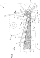
- the winding device 1 shown in the figures is intended for winding flexible and compressible fibrous mattresses, in particular fibrous mattresses with insulating properties made of inorganic fibers such as glass or rock fibers.
- the device 1 comprises a frame 2, which supports a horizontal conveyor belt 3.
- the horizontal belt 3 comprises an endless belt 31 which wraps around two rollers 33 and 35 of parallel and horizontal axes.
- the upper surface of the horizontal belt 3, which is a guide surface for receiving and guiding a fibrous mat 9 in the direction of the arrow F 1 of the figure 3 .
- the device 1 also comprises a back conveyor belt 4 comprising an endless belt 41 which wraps around two rollers 43 and 45 of parallel and horizontal axes.
- Note 47 the surface of the backing mat 4 which is directed towards the surface 37 of the horizontal carpet.
- the surface 47 is a guide surface intended to receive and guide a fibrous mat 9 in the direction of the arrow F 2 of the figure 3 .
- the backing mat 4 is pivotally mounted on a first end 11A of a hydraulic cylinder 11 whose second end is hinged to the frame 2.
- the backing mat 4 is positioned relative to the horizontal mat 3 of such so that the guide surfaces 37 and 47 form between them an acute angle ⁇ of between 60 ° and 90 °, preferably of the order of 75 °.
- the backing belt 4 is able to be lifted away from the horizontal belt 3 under the action of the cylinder 11 to allow the evacuation of a fibrous roll at the end of a winding operation.
- the device 1 further comprises a compression assembly 5, comprising two compression rollers 52 and 54 mounted on the same support 51.
- the rollers 52 and 54 have different diameters, respectively a smaller diameter for the roller 52, for example the order of 125 mm, and a larger diameter for the roller 54, for example of the order of 190 mm.
- the rollers 52 and 54 are rotatably mounted on the support 51 with their axes X 52 and X 54 parallel and horizontal, perpendicular to the direction F 1 advancing of the mattress.
- support 51 is provided for pivoting about an axis X 51 parallel to the axes X 52 and X 54 of the two compression rollers, so as to allow the selection of one of the compression rollers 52, 54 for a winding operation a fibrous mattress.
- the compression roller 52 that has been selected to be active during the winding operation.
- the selected compression roll is rotated about its axis of rotation X 52 or X 54 , in the direction shown by the arrow F 3 of the figure 3 .
- the active compression roller and the guide surfaces 37, 47 of the mats 3 and 4 delimit between them a winding zone 10, in which the fibrous roll is formed.
- the two compression rollers 52 and 54 mounted on the same support 51 offer the possibility of choosing the best suited compression roller according to the characteristics of the fibrous mat to be wound, especially in order to preserve the quality of the mattress at the beginning. winding. Indeed, at the beginning of a winding operation, the mattress can bend and compress locally uncontrollably in the winding zone 10, which can damage the mattress or its surfacing and cause rework variations. thickness.
- the affected mattress portion is shorter as the diameter of the compression roll is small.
- the smaller the diameter of the compression roll the greater the risk of splitting the front edge of the mattress during its turnaround in the core formation phase.
- the length of mattress that forms the core is small, so the use of the higher diameter compression roll is acceptable.
- the support 51 of the compression rollers is connected to the frame 2 of the device by means of two pairs of hydraulic cylinders 6, 8 which are configured to move the support 51, and the compression rollers which are integral therewith, during a winding operation.
- the position of the compression roller 52 or 54 which is active during the winding operation is adjustable, and the compression roller can move away from the guide surface 37 of the horizontal belt 3 as the diameter of the fibrous roll resulting from the winding of the mattress increases.
- each lateral end of the support 51 is connected to a jack 6 and to a jack 8.
- the presence of the two pairs of jacks 6, 8 acting on the lateral ends of the support 51 makes it possible to obtain any trajectory for the active compression roll , while having a rigid device.
- the four jacks 6, 8 can be configured to position the compression roller 52 or 54 which is active during the winding operation on the bisector of the angle ⁇ formed between the guide surface 37 of the belt horizontal 3 and the guide surface 47 of the back mat 4.
- the device 1 also comprises a third conveyor belt 7, called precompression mat, which is disposed above the horizontal mat 3 so that its face 77 positioned facing the guide surface 37 converges with it in the direction of the
- the precompression pad 7 is provided to pre-compress the fibrous mat at a desired compression ratio prior to entering the winding area 10.
- the precompression mat 7 comprises a plurality of endless belts 71 which are parallel to each other and driven in the direction of the arrow F 4 of the figure 3 .
- the precompression belt 7 At its end farthest from the winding zone 10, the precompression belt 7 comprises a single upstream roll 73, around which all the strips 71 are wound.
- the precompression belt 7 also comprises a body 70 housed in the inside of the strips 71, which has a shape of V converging towards the winding zone 10.
- the precompression belt 7 comprises, at its end closest to the winding zone 10, a plurality of downstream rollers 76 which are positioned in the extension of each other, with their axes X 76 coincident and parallel to the X 73 roll axis upstream which is horizontal.
- Each downstream roll 76 serves to wind up one of the strips 71.
- the pre-compression belt 7 comprises, for each downstream roll 76 and each corresponding band 71, two additional rollers 74 and 75, each having their X axis 74 or X 75 parallel to the X axis 76 of the downstream roll and which are arranged within the band 71.
- the first additional roll 74 is juxtaposed with the second additional roll 75, which is itself juxtaposed with the downstream roll 76.
- the band 71 stretched in abutment against the downstream assembly formed by the additional rollers 74 and 75 and the downstream roller 76 juxtaposed defines a precompression scrolling surface 79.
- the precompression belt 7 comprises means for setting in tension of each band 71, not shown in the figures, which are arranged on the side 78 of the pre-compression mat opposite the horizontal mat 3.
- each The downstream roll 76 has a radius of 15 mm, and the additional rollers 74 and 75 are also selected with a radius of 15 mm. More generally, the invention makes it possible to use downstream and additional rollers having radii of between 5 mm and 40 mm, preferably between 5 mm and 20 mm. As shown on the figure 3 each downstream roll 76 is disposed in the winding start configuration between the active compression roller 52 and the guide surface 37 of the horizontal belt 3. This arrangement is made possible by the restricted diameter of each downstream roll 76.
- the precompression surface 79 formed by the band 71 stretched against the rollers 74, 75 and 76 is a homogeneous surface, having a length l of the order of 90 mm in orthogonal projection on the guiding surface 37 of the horizontal carpet 3.
- the precompression surface 79 is thus able to exert a substantially homogeneous pressure force on a slice fibrous mattress length of the order of 90 mm, before entering the winding zone 10.
- the precompression mat 7 comprises a plurality of covers 72, where each cover 72 covers one of the strips 71 at the end of the precompression mat closest to the winding zone 10, while leaving uncovered the precompression surface 79 formed by this band 71. As shown in FIG. figure 6 , each cover 72 extends on the side 78 of the precompression mat opposite the horizontal belt 3, facing the corresponding downstream roller 76 without extending beyond the additional rollers 74 and 75.
- the angle ⁇ of inclination of the precompression surface 79 with respect to the guiding surface 37 is of the order of 10 °. More generally, the angle is advantageously between 5 ° and 15 °, preferably less than or equal to 10 °.
- the distance d 1 between the precompression pad 7 and the guiding surface 37 of the horizontal mat 3 is chosen to be minimum at each downstream roll 76. Thus, the desired compression ratio of the mat entering the winding zone is reached at less at the downstream roll of the precompression mat.
- the distance d 1 between the precompression surface 79 at the downstream roll 76 and the guide surface 37 of the first conveyor belt is adjustable and equal to the desired precompressed thickness of a fibrous mat entering the winding area.
- the position, at the beginning of winding, of the downstream roll 76 between the compression roller 52 and the guiding surface 37 of the first conveyor belt makes it possible to limit as much as possible the re-inflation of the mattress at the exit of the precompression conveyor 7.
- each winding device differs from the device of the first embodiment only in the structure of the downstream assembly of its precompression mat 7.
- the precompression mat 7 is devoid of additional rollers and the body 70 'extends to be juxtaposed with the series of downstream rollers 76.
- the pre-compression scrolling surface 79 is formed, facing the guide surface 37 of the horizontal carpet 3 by the band 71 stretched against the downstream assembly formed by the downstream end of the body 70 'and the downstream roller 76 which is juxtaposed therewith.
- the precompression pad 7 is devoid of both additional rolls and downstream rollers.
- the downstream end around which each of the strips 71 is wound is formed by a curved edge 761 of a thin plate 76 '("knife edge") which extends from the downstream end. of the body 70 in the direction of the winding zone 10.
- the precompression scrolling surface 79 is then formed, facing the guide surface 37 of the horizontal belt 3, by the belt 71 stretched against the downstream assembly formed by the flat portion 762 and the curved edge 761 of the plate 76 '.
- each curved edge 761, centered on a central axis X 761 has a radius of curvature of the order of 10 mm. More generally, the radius of curvature is preferably between 5 mm and 40 mm.
- the winding device 1 operates as follows.
- a fibrous mat 9, positioned on the horizontal mat 3, is driven together by the horizontal mat 3 and the precompression mat 7 towards the winding area 10.
- the mattress 9 is compressed between the guide surface 37 of the horizontal mat 3 and the face 77 of the precompression mat 7.
- the speed of circulation of the strip 71 of the precompression mat 7 by relative to the frame 2 is advantageously adjusted so that its component directed parallel to the direction F 1 of circulation of the guide surface 37 of the horizontal belt 3, that is to say its horizontal component in the example shown, is of the same meaning and same module as the speed of circulation of the guide surface 37 relative to the frame.
- a fibrous core is formed, which corresponds to a first turn of a fibrous roll.
- the contact pressure exerted by the compression roller 52 is controlled by means of the four jacks 6 and 8, so that the fibrous roll being formed remains substantially cylindrical.
- the precompression pad 7 is moved in the direction of the arrow F 5 of the figure 3 .
- the horizontal component of the speed of circulation of the band 71 increases as a function of the speed of the recoil of the precompression mat 7 so as to avoid shearing of the mattress 9.
- a winding device makes it possible to limit the friction exerted on a fibrous mat during its winding, and thus to limit the risk of damaging the mattress, even for high speeds. scroll of the mattress.
- a winder device thanks to the reduced dimensions of the downstream end of the precompression mat, has improved compactness, while maintaining a high compression rate of fibrous mat.
- the precompression mat may comprise a single band 71 and a single downstream end 76, 761.
- the precompression mat may also comprise a plurality of upstream rollers, instead of a single upstream roll 73, each upstream roll corresponding to one of the downstream ends and each band winding around an upstream roll and the corresponding downstream end.
- the number of additional rolls 74, 75 may be different from two, especially the precompression mat may comprise a number n ⁇ 1 of additional rolls, n being preferably equal to 1, 2 or 3.
- two pairs of actuators may be provided to move a conventional compression roll holder carrying a single compression roll, instead of two selectable compression rolls as previously described.
- a compression roller support carrying at least two selectable compression rollers may also be envisaged for a winding device having any precompression means, in particular different from the pre-compression scroll surface carpet 7, and means for displacement of the compression roll support, in particular different from the two pairs of actuators 6, 8.
Landscapes
- Winding Of Webs (AREA)
- Preliminary Treatment Of Fibers (AREA)
- Auxiliary Devices For And Details Of Packaging Control (AREA)
- Treatment Of Fiber Materials (AREA)
- Replacement Of Web Rolls (AREA)
- Nonwoven Fabrics (AREA)
- Controlling Rewinding, Feeding, Winding, Or Abnormalities Of Webs (AREA)
Priority Applications (1)
| Application Number | Priority Date | Filing Date | Title |
|---|---|---|---|
| PL13728496T PL2855312T3 (pl) | 2012-06-04 | 2013-05-27 | Urządzenie do zwijania |
Applications Claiming Priority (2)
| Application Number | Priority Date | Filing Date | Title |
|---|---|---|---|
| FR1255183A FR2991301B1 (fr) | 2012-06-04 | 2012-06-04 | Dispositif enrouleur |
| PCT/FR2013/051162 WO2013182777A1 (fr) | 2012-06-04 | 2013-05-27 | Dispositif enrouleur |
Publications (2)
| Publication Number | Publication Date |
|---|---|
| EP2855312A1 EP2855312A1 (fr) | 2015-04-08 |
| EP2855312B1 true EP2855312B1 (fr) | 2018-02-28 |
Family
ID=46826697
Family Applications (1)
| Application Number | Title | Priority Date | Filing Date |
|---|---|---|---|
| EP13728496.4A Active EP2855312B1 (fr) | 2012-06-04 | 2013-05-27 | Dispositif enrouleur |
Country Status (12)
| Country | Link |
|---|---|
| US (1) | US9701504B2 (https=) |
| EP (1) | EP2855312B1 (https=) |
| JP (1) | JP6228192B2 (https=) |
| CN (1) | CN104520217B (https=) |
| AU (1) | AU2013273359B2 (https=) |
| DK (1) | DK2855312T3 (https=) |
| ES (1) | ES2669558T3 (https=) |
| FR (1) | FR2991301B1 (https=) |
| IN (1) | IN2014DN10287A (https=) |
| PL (1) | PL2855312T3 (https=) |
| RU (1) | RU2629976C2 (https=) |
| WO (1) | WO2013182777A1 (https=) |
Families Citing this family (4)
| Publication number | Priority date | Publication date | Assignee | Title |
|---|---|---|---|---|
| US9868605B2 (en) * | 2014-02-12 | 2018-01-16 | Andrew L. Bishop | Geotextile rolling apparatus |
| CN104911941B (zh) * | 2015-05-19 | 2017-03-08 | 福建汇利丰环保科技有限公司 | 一种可自动卷状收集压浆机输出的纸浆料的收料机构 |
| CN108782654A (zh) * | 2018-06-14 | 2018-11-13 | 广州浩胜弘裕机械设备有限公司 | 一种蛋糕卷层机及其工作方法 |
| US11787655B2 (en) * | 2020-09-28 | 2023-10-17 | C3 Corporation | Variable roll cage machine and process |
Family Cites Families (11)
| Publication number | Priority date | Publication date | Assignee | Title |
|---|---|---|---|---|
| FR2553744B1 (fr) * | 1983-10-21 | 1986-03-28 | Saint Gobain Isover | Enrouleuse a compression asservie |
| SU1594095A1 (ru) * | 1988-05-03 | 1990-09-23 | Специализированный Трест "Белтеплоизоляция" | Устройство дл намотки полосового материала в рулон |
| FR2685904A1 (fr) * | 1992-01-07 | 1993-07-09 | Saint Gobain Isover | Rouleau de matelas fibreux comprime, methode et dispositif pour l'obtenir. |
| US5305963A (en) * | 1992-12-03 | 1994-04-26 | Schuller International, Inc. | Method and apparatus for forming rolls from strips of compressible material |
| FR2731687B1 (fr) * | 1995-03-17 | 1997-04-25 | Tictor Sa | Dispositif enrouleur pour la formation d'un rouleau fibreux comprime |
| DE29604901U1 (de) * | 1996-03-16 | 1996-05-15 | Kaibel & Sieber GmbH, 67547 Worms | Vorrichtung zum Wickeln einer Bahn aus verdichtbarem Material |
| ZA981514B (en) * | 1997-03-07 | 1998-08-28 | Saint Gobain Isover | Winding machine for fibrous mats |
| EP0941952A1 (en) * | 1998-03-09 | 1999-09-15 | Techint Compagnia Tecnica Internazionale S.P.A. | An apparatus for rolling up compressible fibrous materials |
| DE69800627T2 (de) * | 1998-04-07 | 2001-11-15 | Techint Compagnia Tecnica Internazionale S.P.A., Mailand/Milano | Apparat zum Aufrollen von zusammenpressbaren Faserstoffmaterialien |
| FI122646B (fi) * | 2007-11-28 | 2012-05-15 | Paroc Oy Ab | Menetelmä ja laite mineraalivillarullien muodostamiseksi |
| JP5747636B2 (ja) * | 2010-06-03 | 2015-07-15 | セントラル硝子株式会社 | マット巻取り装置 |
-
2012
- 2012-06-04 FR FR1255183A patent/FR2991301B1/fr not_active Expired - Fee Related
-
2013
- 2013-05-27 DK DK13728496.4T patent/DK2855312T3/en active
- 2013-05-27 EP EP13728496.4A patent/EP2855312B1/fr active Active
- 2013-05-27 CN CN201380041506.0A patent/CN104520217B/zh active Active
- 2013-05-27 IN IN10287DEN2014 patent/IN2014DN10287A/en unknown
- 2013-05-27 PL PL13728496T patent/PL2855312T3/pl unknown
- 2013-05-27 US US14/405,506 patent/US9701504B2/en active Active
- 2013-05-27 AU AU2013273359A patent/AU2013273359B2/en active Active
- 2013-05-27 ES ES13728496.4T patent/ES2669558T3/es active Active
- 2013-05-27 RU RU2014153635A patent/RU2629976C2/ru active
- 2013-05-27 JP JP2015515563A patent/JP6228192B2/ja active Active
- 2013-05-27 WO PCT/FR2013/051162 patent/WO2013182777A1/fr not_active Ceased
Also Published As
| Publication number | Publication date |
|---|---|
| DK2855312T3 (en) | 2018-06-14 |
| JP6228192B2 (ja) | 2017-11-08 |
| EP2855312A1 (fr) | 2015-04-08 |
| RU2629976C2 (ru) | 2017-09-05 |
| FR2991301A1 (fr) | 2013-12-06 |
| US20150166287A1 (en) | 2015-06-18 |
| JP2015523287A (ja) | 2015-08-13 |
| IN2014DN10287A (https=) | 2015-08-07 |
| WO2013182777A1 (fr) | 2013-12-12 |
| PL2855312T3 (pl) | 2018-07-31 |
| FR2991301B1 (fr) | 2014-05-23 |
| ES2669558T3 (es) | 2018-05-28 |
| AU2013273359B2 (en) | 2017-06-29 |
| US9701504B2 (en) | 2017-07-11 |
| RU2014153635A (ru) | 2016-07-27 |
| CN104520217B (zh) | 2018-02-23 |
| CN104520217A (zh) | 2015-04-15 |
| AU2013273359A1 (en) | 2015-01-29 |
Similar Documents
| Publication | Publication Date | Title |
|---|---|---|
| EP2855312B1 (fr) | Dispositif enrouleur | |
| EP0140785B1 (fr) | Enrouleuse a compression asservie | |
| EP0040145A1 (fr) | Dispositif pour la coupe de fils continus, notamment de fils de verre | |
| EP0238393B1 (fr) | Perfectionnements aux enrouleuses à compression | |
| EP0734985A1 (fr) | Dispositif enrouleur pour la formation d'un rouleau fibreux comprimé | |
| FR2620117A1 (fr) | Machines diviseuses et reenrouleuses de bande | |
| FR2846643A1 (fr) | Dispositif d'enroulement pour materiaux en forme de bandes, en particulier des films en matiere plastique | |
| CH685126A5 (fr) | Crêpeuse. | |
| EP0914286A1 (fr) | Enrouleuse pour matelas fibreux | |
| EP1552892A1 (fr) | Machine de planage d'une bande metallique | |
| EP0035114B1 (fr) | Machine à presser la paille, le foin et similaires en balles | |
| WO1999010115A1 (fr) | Spiraleuse | |
| EP1711423B1 (fr) | Dispositif d'enroulement a deux rouleaux d'entrainement pour machine a enrouler en continu et procede d'enroulement avec regulation de l'effort d'application des rouleaux d'entrainement | |
| EP0560662B1 (fr) | Procédé et installation de laminage d'une plaque métallique | |
| FR2524253A1 (fr) | Machine de deroulage de balles de produits fibreux enroules suivant une spirale | |
| FR2793382A1 (fr) | Dispositif pour faciliter la formation du noyau de la balle dans une presse a balles rondes de type a chambre a volume variable et presse equipee de ce dispositif | |
| EP0290344B1 (fr) | Procédé et dispositif pour le calandrage des vitrages feuilletés | |
| WO2002027090A1 (fr) | Procede et ensemble de fabrication de feutres en fibres minerales | |
| FR2962427A1 (fr) | Procede pour derouler une bande de papier ou autre que comporte une bobine, et dispositif de devidoir pour la commande du deroulement d'une telle bande | |
| EP1867232B1 (fr) | Dispositif de façonnage de pâtons de pâte alimentaire | |
| EP4588334A1 (fr) | Machine de deroulage d'une balle agricole obtenue par enroulement en spirale d'une nappe continue de tiges vegetales | |
| WO2002068747A1 (fr) | Procede et dispositif de commande d'avance de plaque fibreuse aiguilletee. | |
| FR2725877A1 (fr) | Dispositif pour torsader des saucisses | |
| BE557865A (https=) | ||
| FR2922411A1 (fr) | Procede de gestion de l'entrainement des poulies d'un dispositif de halage d'un cable genre ligne palangre ou filiere de casier et dispositif de halage correspondant |
Legal Events
| Date | Code | Title | Description |
|---|---|---|---|
| PUAI | Public reference made under article 153(3) epc to a published international application that has entered the european phase |
Free format text: ORIGINAL CODE: 0009012 |
|
| 17P | Request for examination filed |
Effective date: 20150105 |
|
| AK | Designated contracting states |
Kind code of ref document: A1 Designated state(s): AL AT BE BG CH CY CZ DE DK EE ES FI FR GB GR HR HU IE IS IT LI LT LU LV MC MK MT NL NO PL PT RO RS SE SI SK SM TR |
|
| AX | Request for extension of the european patent |
Extension state: BA ME |
|
| DAX | Request for extension of the european patent (deleted) | ||
| GRAP | Despatch of communication of intention to grant a patent |
Free format text: ORIGINAL CODE: EPIDOSNIGR1 |
|
| INTG | Intention to grant announced |
Effective date: 20170914 |
|
| GRAS | Grant fee paid |
Free format text: ORIGINAL CODE: EPIDOSNIGR3 |
|
| GRAA | (expected) grant |
Free format text: ORIGINAL CODE: 0009210 |
|
| AK | Designated contracting states |
Kind code of ref document: B1 Designated state(s): AL AT BE BG CH CY CZ DE DK EE ES FI FR GB GR HR HU IE IS IT LI LT LU LV MC MK MT NL NO PL PT RO RS SE SI SK SM TR |
|
| REG | Reference to a national code |
Ref country code: GB Ref legal event code: FG4D Free format text: NOT ENGLISH Ref country code: CH Ref legal event code: EP |
|
| REG | Reference to a national code |
Ref country code: AT Ref legal event code: REF Ref document number: 973855 Country of ref document: AT Kind code of ref document: T Effective date: 20180315 |
|
| REG | Reference to a national code |
Ref country code: IE Ref legal event code: FG4D Free format text: LANGUAGE OF EP DOCUMENT: FRENCH |
|
| REG | Reference to a national code |
Ref country code: DE Ref legal event code: R096 Ref document number: 602013033697 Country of ref document: DE |
|
| REG | Reference to a national code |
Ref country code: SE Ref legal event code: TRGR |
|
| REG | Reference to a national code |
Ref country code: FR Ref legal event code: PLFP Year of fee payment: 6 |
|
| REG | Reference to a national code |
Ref country code: RO Ref legal event code: EPE |
|
| REG | Reference to a national code |
Ref country code: ES Ref legal event code: FG2A Ref document number: 2669558 Country of ref document: ES Kind code of ref document: T3 Effective date: 20180528 |
|
| REG | Reference to a national code |
Ref country code: NL Ref legal event code: FP |
|
| REG | Reference to a national code |
Ref country code: DK Ref legal event code: T3 Effective date: 20180607 |
|
| REG | Reference to a national code |
Ref country code: LT Ref legal event code: MG4D |
|
| REG | Reference to a national code |
Ref country code: AT Ref legal event code: MK05 Ref document number: 973855 Country of ref document: AT Kind code of ref document: T Effective date: 20180228 |
|
| PG25 | Lapsed in a contracting state [announced via postgrant information from national office to epo] |
Ref country code: CY Free format text: LAPSE BECAUSE OF FAILURE TO SUBMIT A TRANSLATION OF THE DESCRIPTION OR TO PAY THE FEE WITHIN THE PRESCRIBED TIME-LIMIT Effective date: 20180228 Ref country code: NO Free format text: LAPSE BECAUSE OF FAILURE TO SUBMIT A TRANSLATION OF THE DESCRIPTION OR TO PAY THE FEE WITHIN THE PRESCRIBED TIME-LIMIT Effective date: 20180528 Ref country code: HR Free format text: LAPSE BECAUSE OF FAILURE TO SUBMIT A TRANSLATION OF THE DESCRIPTION OR TO PAY THE FEE WITHIN THE PRESCRIBED TIME-LIMIT Effective date: 20180228 Ref country code: LT Free format text: LAPSE BECAUSE OF FAILURE TO SUBMIT A TRANSLATION OF THE DESCRIPTION OR TO PAY THE FEE WITHIN THE PRESCRIBED TIME-LIMIT Effective date: 20180228 |
|
| PG25 | Lapsed in a contracting state [announced via postgrant information from national office to epo] |
Ref country code: AT Free format text: LAPSE BECAUSE OF FAILURE TO SUBMIT A TRANSLATION OF THE DESCRIPTION OR TO PAY THE FEE WITHIN THE PRESCRIBED TIME-LIMIT Effective date: 20180228 Ref country code: RS Free format text: LAPSE BECAUSE OF FAILURE TO SUBMIT A TRANSLATION OF THE DESCRIPTION OR TO PAY THE FEE WITHIN THE PRESCRIBED TIME-LIMIT Effective date: 20180228 Ref country code: BG Free format text: LAPSE BECAUSE OF FAILURE TO SUBMIT A TRANSLATION OF THE DESCRIPTION OR TO PAY THE FEE WITHIN THE PRESCRIBED TIME-LIMIT Effective date: 20180528 Ref country code: GR Free format text: LAPSE BECAUSE OF FAILURE TO SUBMIT A TRANSLATION OF THE DESCRIPTION OR TO PAY THE FEE WITHIN THE PRESCRIBED TIME-LIMIT Effective date: 20180529 Ref country code: LV Free format text: LAPSE BECAUSE OF FAILURE TO SUBMIT A TRANSLATION OF THE DESCRIPTION OR TO PAY THE FEE WITHIN THE PRESCRIBED TIME-LIMIT Effective date: 20180228 |
|
| PG25 | Lapsed in a contracting state [announced via postgrant information from national office to epo] |
Ref country code: MT Free format text: LAPSE BECAUSE OF FAILURE TO SUBMIT A TRANSLATION OF THE DESCRIPTION OR TO PAY THE FEE WITHIN THE PRESCRIBED TIME-LIMIT Effective date: 20180228 |
|
| PG25 | Lapsed in a contracting state [announced via postgrant information from national office to epo] |
Ref country code: EE Free format text: LAPSE BECAUSE OF FAILURE TO SUBMIT A TRANSLATION OF THE DESCRIPTION OR TO PAY THE FEE WITHIN THE PRESCRIBED TIME-LIMIT Effective date: 20180228 Ref country code: AL Free format text: LAPSE BECAUSE OF FAILURE TO SUBMIT A TRANSLATION OF THE DESCRIPTION OR TO PAY THE FEE WITHIN THE PRESCRIBED TIME-LIMIT Effective date: 20180228 |
|
| REG | Reference to a national code |
Ref country code: DE Ref legal event code: R097 Ref document number: 602013033697 Country of ref document: DE |
|
| PG25 | Lapsed in a contracting state [announced via postgrant information from national office to epo] |
Ref country code: SM Free format text: LAPSE BECAUSE OF FAILURE TO SUBMIT A TRANSLATION OF THE DESCRIPTION OR TO PAY THE FEE WITHIN THE PRESCRIBED TIME-LIMIT Effective date: 20180228 Ref country code: SK Free format text: LAPSE BECAUSE OF FAILURE TO SUBMIT A TRANSLATION OF THE DESCRIPTION OR TO PAY THE FEE WITHIN THE PRESCRIBED TIME-LIMIT Effective date: 20180228 |
|
| REG | Reference to a national code |
Ref country code: CH Ref legal event code: PL |
|
| PLBE | No opposition filed within time limit |
Free format text: ORIGINAL CODE: 0009261 |
|
| STAA | Information on the status of an ep patent application or granted ep patent |
Free format text: STATUS: NO OPPOSITION FILED WITHIN TIME LIMIT |
|
| PG25 | Lapsed in a contracting state [announced via postgrant information from national office to epo] |
Ref country code: MC Free format text: LAPSE BECAUSE OF FAILURE TO SUBMIT A TRANSLATION OF THE DESCRIPTION OR TO PAY THE FEE WITHIN THE PRESCRIBED TIME-LIMIT Effective date: 20180228 |
|
| 26N | No opposition filed |
Effective date: 20181129 |
|
| REG | Reference to a national code |
Ref country code: IE Ref legal event code: MM4A |
|
| PG25 | Lapsed in a contracting state [announced via postgrant information from national office to epo] |
Ref country code: CH Free format text: LAPSE BECAUSE OF NON-PAYMENT OF DUE FEES Effective date: 20180531 Ref country code: SI Free format text: LAPSE BECAUSE OF FAILURE TO SUBMIT A TRANSLATION OF THE DESCRIPTION OR TO PAY THE FEE WITHIN THE PRESCRIBED TIME-LIMIT Effective date: 20180228 Ref country code: LI Free format text: LAPSE BECAUSE OF NON-PAYMENT OF DUE FEES Effective date: 20180531 |
|
| PG25 | Lapsed in a contracting state [announced via postgrant information from national office to epo] |
Ref country code: IE Free format text: LAPSE BECAUSE OF NON-PAYMENT OF DUE FEES Effective date: 20180527 |
|
| PG25 | Lapsed in a contracting state [announced via postgrant information from national office to epo] |
Ref country code: PT Free format text: LAPSE BECAUSE OF FAILURE TO SUBMIT A TRANSLATION OF THE DESCRIPTION OR TO PAY THE FEE WITHIN THE PRESCRIBED TIME-LIMIT Effective date: 20180228 |
|
| PG25 | Lapsed in a contracting state [announced via postgrant information from national office to epo] |
Ref country code: MK Free format text: LAPSE BECAUSE OF NON-PAYMENT OF DUE FEES Effective date: 20180228 Ref country code: HU Free format text: LAPSE BECAUSE OF FAILURE TO SUBMIT A TRANSLATION OF THE DESCRIPTION OR TO PAY THE FEE WITHIN THE PRESCRIBED TIME-LIMIT; INVALID AB INITIO Effective date: 20130527 |
|
| PG25 | Lapsed in a contracting state [announced via postgrant information from national office to epo] |
Ref country code: IS Free format text: LAPSE BECAUSE OF FAILURE TO SUBMIT A TRANSLATION OF THE DESCRIPTION OR TO PAY THE FEE WITHIN THE PRESCRIBED TIME-LIMIT Effective date: 20180628 |
|
| P01 | Opt-out of the competence of the unified patent court (upc) registered |
Effective date: 20230421 |
|
| PGFP | Annual fee paid to national office [announced via postgrant information from national office to epo] |
Ref country code: NL Payment date: 20250409 Year of fee payment: 13 |
|
| PGFP | Annual fee paid to national office [announced via postgrant information from national office to epo] |
Ref country code: FI Payment date: 20250513 Year of fee payment: 13 |
|
| PGFP | Annual fee paid to national office [announced via postgrant information from national office to epo] |
Ref country code: PL Payment date: 20250409 Year of fee payment: 13 Ref country code: DE Payment date: 20250402 Year of fee payment: 13 |
|
| PGFP | Annual fee paid to national office [announced via postgrant information from national office to epo] |
Ref country code: DK Payment date: 20250516 Year of fee payment: 13 Ref country code: ES Payment date: 20250605 Year of fee payment: 13 |
|
| PGFP | Annual fee paid to national office [announced via postgrant information from national office to epo] |
Ref country code: LU Payment date: 20250516 Year of fee payment: 13 Ref country code: BE Payment date: 20250410 Year of fee payment: 13 Ref country code: IT Payment date: 20250422 Year of fee payment: 13 |
|
| PGFP | Annual fee paid to national office [announced via postgrant information from national office to epo] |
Ref country code: FR Payment date: 20250401 Year of fee payment: 13 |
|
| PGFP | Annual fee paid to national office [announced via postgrant information from national office to epo] |
Ref country code: RO Payment date: 20250415 Year of fee payment: 13 |
|
| PGFP | Annual fee paid to national office [announced via postgrant information from national office to epo] |
Ref country code: TR Payment date: 20250516 Year of fee payment: 13 |
|
| PGFP | Annual fee paid to national office [announced via postgrant information from national office to epo] |
Ref country code: CZ Payment date: 20250519 Year of fee payment: 13 |
|
| PGFP | Annual fee paid to national office [announced via postgrant information from national office to epo] |
Ref country code: SE Payment date: 20250411 Year of fee payment: 13 |
|
| PGFP | Annual fee paid to national office [announced via postgrant information from national office to epo] |
Ref country code: GB Payment date: 20260325 Year of fee payment: 14 |