EP2853762A1 - Wälzlagereinheit mit montageplatte und verfahren zur herstellung davon - Google Patents
Wälzlagereinheit mit montageplatte und verfahren zur herstellung davon Download PDFInfo
- Publication number
- EP2853762A1 EP2853762A1 EP13810076.3A EP13810076A EP2853762A1 EP 2853762 A1 EP2853762 A1 EP 2853762A1 EP 13810076 A EP13810076 A EP 13810076A EP 2853762 A1 EP2853762 A1 EP 2853762A1
- Authority
- EP
- European Patent Office
- Prior art keywords
- retainer plate
- diameter
- outer ring
- axial direction
- circumferential
- Prior art date
- Legal status (The legal status is an assumption and is not a legal conclusion. Google has not performed a legal analysis and makes no representation as to the accuracy of the status listed.)
- Granted
Links
- 238000005096 rolling process Methods 0.000 title claims abstract description 71
- 238000004519 manufacturing process Methods 0.000 title claims description 13
- 238000000034 method Methods 0.000 title description 7
- 230000000452 restraining effect Effects 0.000 claims description 10
- 238000006073 displacement reaction Methods 0.000 claims description 9
- 238000003825 pressing Methods 0.000 claims description 8
- 238000010276 construction Methods 0.000 description 27
- 230000005540 biological transmission Effects 0.000 description 6
- 238000010586 diagram Methods 0.000 description 3
- 239000002184 metal Substances 0.000 description 3
- 229910001209 Low-carbon steel Inorganic materials 0.000 description 2
- 229910000831 Steel Inorganic materials 0.000 description 2
- 230000007423 decrease Effects 0.000 description 2
- 239000007769 metal material Substances 0.000 description 2
- 239000010959 steel Substances 0.000 description 2
- 238000005520 cutting process Methods 0.000 description 1
- 238000009826 distribution Methods 0.000 description 1
- 230000000694 effects Effects 0.000 description 1
- 238000005304 joining Methods 0.000 description 1
- 230000001105 regulatory effect Effects 0.000 description 1
- 238000000926 separation method Methods 0.000 description 1
Images


Classifications
-
- F—MECHANICAL ENGINEERING; LIGHTING; HEATING; WEAPONS; BLASTING
- F16—ENGINEERING ELEMENTS AND UNITS; GENERAL MEASURES FOR PRODUCING AND MAINTAINING EFFECTIVE FUNCTIONING OF MACHINES OR INSTALLATIONS; THERMAL INSULATION IN GENERAL
- F16C—SHAFTS; FLEXIBLE SHAFTS; ELEMENTS OR CRANKSHAFT MECHANISMS; ROTARY BODIES OTHER THAN GEARING ELEMENTS; BEARINGS
- F16C35/00—Rigid support of bearing units; Housings, e.g. caps, covers
- F16C35/04—Rigid support of bearing units; Housings, e.g. caps, covers in the case of ball or roller bearings
- F16C35/06—Mounting or dismounting of ball or roller bearings; Fixing them onto shaft or in housing
- F16C35/067—Fixing them in a housing
-
- F—MECHANICAL ENGINEERING; LIGHTING; HEATING; WEAPONS; BLASTING
- F16—ENGINEERING ELEMENTS AND UNITS; GENERAL MEASURES FOR PRODUCING AND MAINTAINING EFFECTIVE FUNCTIONING OF MACHINES OR INSTALLATIONS; THERMAL INSULATION IN GENERAL
- F16C—SHAFTS; FLEXIBLE SHAFTS; ELEMENTS OR CRANKSHAFT MECHANISMS; ROTARY BODIES OTHER THAN GEARING ELEMENTS; BEARINGS
- F16C19/00—Bearings with rolling contact, for exclusively rotary movement
- F16C19/02—Bearings with rolling contact, for exclusively rotary movement with bearing balls essentially of the same size in one or more circular rows
- F16C19/04—Bearings with rolling contact, for exclusively rotary movement with bearing balls essentially of the same size in one or more circular rows for radial load mainly
- F16C19/06—Bearings with rolling contact, for exclusively rotary movement with bearing balls essentially of the same size in one or more circular rows for radial load mainly with a single row or balls
-
- F—MECHANICAL ENGINEERING; LIGHTING; HEATING; WEAPONS; BLASTING
- F16—ENGINEERING ELEMENTS AND UNITS; GENERAL MEASURES FOR PRODUCING AND MAINTAINING EFFECTIVE FUNCTIONING OF MACHINES OR INSTALLATIONS; THERMAL INSULATION IN GENERAL
- F16C—SHAFTS; FLEXIBLE SHAFTS; ELEMENTS OR CRANKSHAFT MECHANISMS; ROTARY BODIES OTHER THAN GEARING ELEMENTS; BEARINGS
- F16C33/00—Parts of bearings; Special methods for making bearings or parts thereof
- F16C33/30—Parts of ball or roller bearings
- F16C33/58—Raceways; Race rings
- F16C33/583—Details of specific parts of races
- F16C33/586—Details of specific parts of races outside the space between the races, e.g. end faces or bore of inner ring
-
- F—MECHANICAL ENGINEERING; LIGHTING; HEATING; WEAPONS; BLASTING
- F16—ENGINEERING ELEMENTS AND UNITS; GENERAL MEASURES FOR PRODUCING AND MAINTAINING EFFECTIVE FUNCTIONING OF MACHINES OR INSTALLATIONS; THERMAL INSULATION IN GENERAL
- F16C—SHAFTS; FLEXIBLE SHAFTS; ELEMENTS OR CRANKSHAFT MECHANISMS; ROTARY BODIES OTHER THAN GEARING ELEMENTS; BEARINGS
- F16C35/00—Rigid support of bearing units; Housings, e.g. caps, covers
- F16C35/04—Rigid support of bearing units; Housings, e.g. caps, covers in the case of ball or roller bearings
- F16C35/042—Housings for rolling element bearings for rotary movement
- F16C35/045—Housings for rolling element bearings for rotary movement with a radial flange to mount the housing
-
- F—MECHANICAL ENGINEERING; LIGHTING; HEATING; WEAPONS; BLASTING
- F16—ENGINEERING ELEMENTS AND UNITS; GENERAL MEASURES FOR PRODUCING AND MAINTAINING EFFECTIVE FUNCTIONING OF MACHINES OR INSTALLATIONS; THERMAL INSULATION IN GENERAL
- F16C—SHAFTS; FLEXIBLE SHAFTS; ELEMENTS OR CRANKSHAFT MECHANISMS; ROTARY BODIES OTHER THAN GEARING ELEMENTS; BEARINGS
- F16C35/00—Rigid support of bearing units; Housings, e.g. caps, covers
- F16C35/04—Rigid support of bearing units; Housings, e.g. caps, covers in the case of ball or roller bearings
- F16C35/06—Mounting or dismounting of ball or roller bearings; Fixing them onto shaft or in housing
-
- F—MECHANICAL ENGINEERING; LIGHTING; HEATING; WEAPONS; BLASTING
- F16—ENGINEERING ELEMENTS AND UNITS; GENERAL MEASURES FOR PRODUCING AND MAINTAINING EFFECTIVE FUNCTIONING OF MACHINES OR INSTALLATIONS; THERMAL INSULATION IN GENERAL
- F16C—SHAFTS; FLEXIBLE SHAFTS; ELEMENTS OR CRANKSHAFT MECHANISMS; ROTARY BODIES OTHER THAN GEARING ELEMENTS; BEARINGS
- F16C19/00—Bearings with rolling contact, for exclusively rotary movement
- F16C19/54—Systems consisting of a plurality of bearings with rolling friction
-
- F—MECHANICAL ENGINEERING; LIGHTING; HEATING; WEAPONS; BLASTING
- F16—ENGINEERING ELEMENTS AND UNITS; GENERAL MEASURES FOR PRODUCING AND MAINTAINING EFFECTIVE FUNCTIONING OF MACHINES OR INSTALLATIONS; THERMAL INSULATION IN GENERAL
- F16C—SHAFTS; FLEXIBLE SHAFTS; ELEMENTS OR CRANKSHAFT MECHANISMS; ROTARY BODIES OTHER THAN GEARING ELEMENTS; BEARINGS
- F16C2220/00—Shaping
- F16C2220/40—Shaping by deformation without removing material
-
- F—MECHANICAL ENGINEERING; LIGHTING; HEATING; WEAPONS; BLASTING
- F16—ENGINEERING ELEMENTS AND UNITS; GENERAL MEASURES FOR PRODUCING AND MAINTAINING EFFECTIVE FUNCTIONING OF MACHINES OR INSTALLATIONS; THERMAL INSULATION IN GENERAL
- F16C—SHAFTS; FLEXIBLE SHAFTS; ELEMENTS OR CRANKSHAFT MECHANISMS; ROTARY BODIES OTHER THAN GEARING ELEMENTS; BEARINGS
- F16C2226/00—Joining parts; Fastening; Assembling or mounting parts
- F16C2226/50—Positive connections
- F16C2226/60—Positive connections with threaded parts, e.g. bolt and nut connections
-
- F—MECHANICAL ENGINEERING; LIGHTING; HEATING; WEAPONS; BLASTING
- F16—ENGINEERING ELEMENTS AND UNITS; GENERAL MEASURES FOR PRODUCING AND MAINTAINING EFFECTIVE FUNCTIONING OF MACHINES OR INSTALLATIONS; THERMAL INSULATION IN GENERAL
- F16C—SHAFTS; FLEXIBLE SHAFTS; ELEMENTS OR CRANKSHAFT MECHANISMS; ROTARY BODIES OTHER THAN GEARING ELEMENTS; BEARINGS
- F16C2361/00—Apparatus or articles in engineering in general
- F16C2361/61—Toothed gear systems, e.g. support of pinion shafts
-
- F—MECHANICAL ENGINEERING; LIGHTING; HEATING; WEAPONS; BLASTING
- F16—ENGINEERING ELEMENTS AND UNITS; GENERAL MEASURES FOR PRODUCING AND MAINTAINING EFFECTIVE FUNCTIONING OF MACHINES OR INSTALLATIONS; THERMAL INSULATION IN GENERAL
- F16C—SHAFTS; FLEXIBLE SHAFTS; ELEMENTS OR CRANKSHAFT MECHANISMS; ROTARY BODIES OTHER THAN GEARING ELEMENTS; BEARINGS
- F16C33/00—Parts of bearings; Special methods for making bearings or parts thereof
- F16C33/30—Parts of ball or roller bearings
- F16C33/58—Raceways; Race rings
Definitions
- the present invention relates to a rolling bearing unit with retainer plate that is used for rotatably supporting the end section of a rotating shaft of an automobile transmission or the like on the inside surface of a housing, and to the manufacturing method thereof.
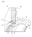
- the end section of a rotating shaft 1 such as a counter shaft of an automobile transmission is rotatably supported by a radial rolling bearing 3 such as a single-row deep-groove ball bearing on the inside surface of a housing 2 that houses part of the automobile transmission.
- a circular concave support section 4 is provided on the inside surface of the housing 2, and the outer ring 5 of the radial rolling bearing 3 is fastened inside this concave support section 4 with an interference fit.
- the end section of the rotating shaft 1 is fitted inside the inner ring 6 of the radial rolling bearing 3 with an interference fit or the like so that there is no looseness in the radial direction.
- the outer ring 5 is prevented from coming apart from the concave support section 4 by being held down toward the rear section of the concave support section 4 by a retainer plate 7.
- FIG. 12 and FIG. 13 illustrate an example of a rolling bearing unit with retainer plate.
- This rolling bearing unit with retainer plate 8 is constructed by fitting a retainer plate 7 around a small-diameter stepped section 9 that is provided on one end in the axial direction of the outer-circumferential surface of the outer ring 5 of a radial rolling bearing 3 so as to be able to rotate with respect to the outer ring 5.
- the rolling bearing unit with retainer plate 8 is assembled inside the housing 2 by fitting the outer ring 5 inside the concave support section 4 with an interference fit, and bringing one surface of the retainer plate 7 in contact with the inside surface of the housing 2. Furthermore, the retainer plate 7 is rotated with respect to the outer ring 5 to align mounting holes 10, which are screw holes or through holes, with through holes or screw holes (not illustrated in the figures) that are formed in the inside surface of the housing 2, and by screwing the retainer plate 7 to the housing with screws or bolts, the outer ring 5 is supported by and fastened inside the concave support section 4 in a state such that there is no looseness and so as to be prevented from coming apart from the concave support section 4.
- the retainer plate 7 is joined with the outer ring 5 so that relative rotation is possible and so as not to become separated.
- the reason for making rotation possible is so that after the outer ring 5 has been fitted inside the concave support section 4 with an interference fit or the like in a state such that looseness in the radial direction is prevented, the mounting holes 10 of the retainer plate 7 can be aligned with the through holes or screw holes of the housing 2.
- the reason for making separation not possible is so that the radial rolling bearing 3 and retainer plate 7 can be handled as a single unit, which simplifies the management of parts and the assembly work.
- the plastically deformed portions on part of the inner-circumferential edge of the retainer plate 7 that are formed by pressing by the punch 15 before the engagement protrusions 11 are formed are prevented from coming in contact with the end section in the axial direction of the small-diameter stepped section 9.
- the amount of run-out (maximum eccentricity) of the retainer plate 7 with respect to the outer ring 5 becomes large, so unless the engagement protrusions 11 are made sufficiently high and the engagement groove 12 sufficiently deep, there is a problem in that it becomes easy for the engagement protrusions 11 to come apart from the engagement groove 12.
- JP 2009-036319 A manufacturing method is disclosed in JP 2009-036319 (A ) in which plural engagement protrusions are formed around the circumferential edge of the support hole that is provided in the retainer plate before the retainer plate and outer ring are combined, and then the retainer plate and outer ring are combined while being elastically deformed.
- a manufacturing method is disclosed in JP 2009-036319 (A ) in which plural engagement protrusions are formed around the circumferential edge of the support hole that is provided in the retainer plate before the retainer plate and outer ring are combined, and then the retainer plate and outer ring are combined while being elastically deformed.
- the object of the present invention is to provide a low-cost rolling bearing unit with retainer plate that can be easily handled and that maintains concentricity of the outer ring and retainer plate without the occurrence of harmful deformation of the outer ring.
- the rolling bearing unit with retainer plate of the present invention has: an outer ring; an inner ring; plural rolling bodies; and a retainer plate.
- the outer ring has an outer ring raceway around the inner-circumferential surface thereof.
- the inner ring is arranged to be concentric with the outer ring and has an inner ring raceway around the outer-circumferential surface thereof.
- the plural rolling bodies are provided between the outer ring raceway and the inner ring raceway so as to rotate freely.
- the retainer plate has a support hole and plural mounting holes that are provided around the support hole.
- a small-diameter stepped section is provided completely around one end section in the axial direction of the outer-circumferential surface of the outer ring, and an engagement groove that extends in the circumferential direction is provided around the portion further close to the middle in the axial direction than the end section in the axial direction of the small-diameter stepped section.
- the support hole in the retainer plate has an inner diameter that is larger than the outer diameter of the small-diameter stepped section, and is less than the outer diameter of the portion of the outer-circumferential surface of the outer ring that is adjacent in the axial direction to the small-diameter stepped section.
- Large-diameter sections that are recessed outward in the radial direction of the inner-circumferential edge of the support hole are provided at plural locations in the circumferential direction of the support hole.
- Engagement protrusions that protrude inward in the radial direction from the circumferential edge of the large-diameter sections are provided on parts of those circumferential edges of the large-diameter sections, and the diameter of the inscribed circle of the engagement protrusions is less than the outer diameter of the end section in the axial direction of the small-diameter stepped section, and equal to or greater than the diameter of the bottom section of the engagement groove.
- the outer ring and the retainer plate are combined so as not to come apart by the engagement protrusions engaging with the engagement groove so that relative movement in the circumferential direction is possible.
- the large-diameter sections and the engagement protrusions are provided at plural locations in the circumferential direction, and preferably at three or more locations that are uniformly spaced in the circumferential direction.
- the engagement groove is provided on the portion except the end section in the axial direction of the small-diameter stepped section so as to extend in at least the circumferential direction.
- the engagement groove is provided on the portion except the end section in the axial direction of the small-diameter stepped section, which is from the middle section in the axial direction to the base section in the axial direction, and completely around the small-diameter stepped section.
- the engagement groove is provided on the portion except the end section in the axial direction and the base section in the axial direction of the small-diameter stepped section, which is the middle section in the axial direction, completely around the small-diameter stepped section.
- notches that extend in the circumferential direction, with the diameter of the circumscribed circle thereof being greater than the outer diameter of the outer ring, are formed in portions of the inner-circumferential edge of the support hole where the phase in the circumferential direction coincides with the plural mounting holes, and the portions close to the inner diameter of the one side surface in the axial direction of the retainer plate and the step surface that extends in the radial direction between the outer-circumferential surface of the outer ring and the base section of the small-diameter stepped section engage at positions where the phase in the circumferential direction differs from the plural mounting holes.
- the present invention can be applied to a rolling bearing unit with retainer plate in which only one support hole is provided in the retainer plate, and in that case, the outer ring and retainer plate are combined such that relative displacement in the circumferential direction of the outer ring is possible.
- the present invention can be applied to a rolling bearing unit with retainer plate in which plural support holes are provided, and in that case the outer ring and retainer plate are combined so that relative displacement in the radial direction of the support holes is possible.
- the diameter of the inscribed circle of the mounting holes in the retainer plate is greater than the outer diameter of the outer ring.
- the rolling bearing with retainer plate of the present invention can be obtained by a manufacturing method having a step of plastically deforming parts of the circumferential edges of the large-diameter sections on the surface of the other side in the axial direction of the retainer plate inward in the radial direction to form the engagement protrusions, by pressing the parts of the circumferential edges of the large-diameter sections toward the step surface that extends in the radial direction between the outer-circumferential surface of the outer ring and the base section of the small-diameter stepped section of the outer ring, with the small-diameter stepped section fitted inside the support hole of the retainer plate before the engagement protrusions are formed, combining the outer ring and retainer plate by engaging the engagement protrusions with the engagement groove.
- the engagement protrusions can be formed by pressing a wedge-shaped first punch against the parts of the circumferential edges of the large-diameter sections of the other side surface in the axial direction of the retainer plate before the engagement protrusions are formed to form V-shaped concave grooves that open on the side of the other side surface in the axial direction of the retainer plate, causing the portions of the parts of the circumferential edges of the large-diameter sections that are located further on the inside in the radial direction than the concave grooves to plastically deform inward in the radial direction, and then by pressing a second punch inside the concave grooves causing the portions that are located further on the inside in the radial direction than the concave grooves to plastically deform further in the radial direction.
- a restraining jig is arranged around the outer ring so as to surround the outer ring, and by supporting the intermediate portion in the radial direction of the one side surface in the axial direction of the retainer plate with the restraining jig when forming the engagement protrusions, the processing load is prevented from being applied to the outer ring.
- engagement protrusions on the retainer plate side that engage with the engagement groove on the outer ring side are formed by plastically deforming parts of the circumferential edges of large-diameter sections that are provided at plural locations on the inner-circumferential edge of the retainer plate, so during the processing of the engagement protrusions, portions of the retainer plate that are plastically deformed come in contact with the end section in the axial direction of the small-diameter stepped section of the outer ring, and so these portions do not strongly press the outer-circumferential surface of the small-diameter section inward in the radial direction. Therefore, harmful forces do not act on any of the parts when combining the outer ring and the retainer plate, and harmful deformation of these parts is prevented, so it is possible to improve the yield of the rolling bearing unit with retainer plate.
- the inner-circumferential surface of the retainer plate and the outer-circumferential surface of the small-diameter stepped section face each other through a minute gap except in the portions of the large-diameter sections. Therefore, it is possible to keep the amount of torsional rotation (maximum eccentricity) of the retainer plate with respect to the outer ring to a very small amount, and thus it is possible to maintain concentricity of the outer ring and retainer plate.
- the construction of the present invention is construction in which it is possible to combine the outer ring and retainer plate directly without the use of separate parts, so it is possible to suppress the manufacturing costs of parts, the cost of managing parts, and assembly costs, and thus it is possible to lower the cost of the rolling bearing unit with retainer plate.
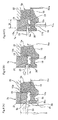
- FIG. 1 to FIG. 4 illustrate a first example of an embodiment of the present invention.
- the rolling bearing unit with retainer plate 8a of this example is constructed by combining together a radial rolling bearing 3a (see FIG. 10 ) and a retainer plate 7a so that relative rotation is possible and so as not to come apart.
- the radial rolling bearing 3a as in the conventional construction, has: an outer ring 5a; an inner ring 6 (see FIG. 10 ); and plural balls 24 as rolling bodies (see FIG. 10 ).
- the inner ring 6 is made of a hard metal such as bearing steel and formed to have a complete circular ring shape, with a single-row deep-groove inner ring raceway provided around the middle section in the axial direction of the outer-circumferential surface thereof, and arranged so as to be concentric with the outer ring 5a.
- the balls 24 as rolling bodies are provided between the outer ring raceway 16 of the outer ring 5a and the inner ring raceway of the inner ring 6.
- the present invention can be widely used in radial rolling bearing units with retainer plate regardless of the type, however, particularly, in the present invention, a single-row deep-groove ball bearing is preferably used as the radial rolling bearing 3a.
- the reason for this is because the dynamic torque is low, and even in the state before being assembled in the rotational-support section, none of the components become accidentally separated.
- the following explanation will center on the features of this example, which are the construction for the portion where the outer ring 5a of the radial rolling bearing 3a and the retainer plate 7a are combined, and the method of assembling the outer ring 5a and retainer plate 7a.
- the radial rolling bearing 3a preferably has a retainer 25 (see FIG. 10 ).
- the outer ring 5a is made of a hard metal such as bearing steel and formed to have a complete circular ring shape, and a single-row deep-groove outer ring raceway 16 is formed completely around the middle section in the axial direction of the inner-circumferential surface thereof, and engagement grooves 18 in which the outer-circumferential edge of a seal ring 17 (see FIG. 14 ) is locked are formed on both end sections in the axial direction.
- a small-diameter stepped section 9a having a diameter that is less than the outer diameter of the outer-circumferential surface of the outer ring 5a is formed all around one end section (left end section in FIG. 2 and FIG.
- an engagement groove 12a is provided all around the portion further close to the middle section in axial direction than the end section in the axial direction (left end section in FIG.2 and FIG. 4 ) of the outer-circumferential surface of the small-diameter stepped section 9a, or more specifically, in this example, the entire portion from the middle section in the axial direction to the base section in the axial direction of the small-diameter stepped section 9a except the end section in the axial direction of the small-diameter stepped section 9a.
- an embankment shaped engagement ridge section 20 is formed all around the end section in the axial direction of the small-diameter stepped section 9a (tip end section), or in other words, the portion between the engagement groove 12a and the tip-end surface of the small-diameter stepped section 9a.
- the retainer plate 7a is made of a plastically deformable metal plate such as mild steel plate and has a hexagonal shape that appears to be formed by cutting away the corners of an equilateral triangle into partial arc shapes, with one support hole 13a being provided in the center section thereof.
- Mounting holes 10a are provided at three locations that are uniformly spaced in the circumferential direction around the support hole 13a of the retainer plate 7a.
- the thickness T of the retainer plate 7a is the same as the length L of the small-diameter stepped section 9a (T ⁇ L), and greater than the width W of the engagement groove 12a (T > W).
- the inner diameter R 13 of the support hole 13a (inner diameter of the portion separated in the circumferential direction of the large-diameter section 21 that is formed in a state of being recessed toward the outside in the radial direction from the inner-circumferential edge of the support hole 13a) (see FIG. 3 ) is a little greater than the outer diameter d 9 of the small-diameter stepped section 9a (see FIG. 1 and FIG. 4 ), and less than the outer diameter D (see FIG. 4 ) of the portion of the outer ring 5a that is adjacent in the axial direction to the small-diameter stepped section 9a (d 9 ⁇ R 13 ⁇ D).
- the difference between the inner diameter R 13 of the support hole 13a and the outer diameter d 9 of the small-diameter stepped section 9a is small. Therefore, it is possible to suppress the amount of rotation of the retainer plate 7a with respect to the outer ring 5a, and thus the work of screwing and fastening the retainer plate 7a to the housing 2 (see FIG. 11 ) becomes easy, and it is possible to improve the ease of handling the rolling bearing unit with retainer plate 8a.
- the difference between the inner diameter R 13 and the outer diameter d 9 (R 13 - d 9 ) is preferably 0.01% to 2% the inner diameter R 13 , and more preferably 0.01% to 1%.
- notch shaped large diameter sections 21 are formed at three locations that are uniformly spaced in the circumferential direction of the support hole 13a in a state so as to be further recessed in a direction toward the outside in the radial direction than the adjacent portions in the circumferential direction.
- the diameter R 11a of the inscribed circle of these engagement protrusions 11a is less than the outer diameter d 9 of the engagement ridge section 20 that is provided on the end section in the axial direction of the small-diameter stepped section 9a, and equal to or greater than the diameter d 12a of the bottom section of the engagement groove 12a (d 12 a ⁇ R 11a ⁇ d 9 ), and is preferably greater than the diameter d 12a (d 12a ⁇ R 11a ⁇ d 9 ).
- the outer ring 5a that is provided with a small-diameter stepped section 9a (engagement ridge section 20 and engagement groove 12a), and the retainer plate 7a that has large-diameter sections 21 and engagement protrusions 11a are fitted together so that relative rotation is possible and so as not to come apart by causing the engagement protrusions 11a to engage with the engagement groove 12a.
- the engagement protrusions 11a are caused to engage with the engagement groove 12a so that relative rotation is possible, and the portion close to the inner diameter of the one side surface in the axial direction of the retainer plate 7a (surface on the right side in FIG. 2 and FIG. 4 ) is caused to engage with the step surface 19. In this state, displacement toward the left in FIG.
- the thickness T 11a of the engagement protrusions 11a in the axial direction with regard to the retainer plate 7a and outer ring 5a is less than the width W of the engagement groove 12a (T 11a ⁇ W).
- an engagement groove 12a is provided around the enter circumference, however, alternatively, it is also possible to provide engagement grooves that extend in the circumferential direction at plural locations at positions that are aligned with the large-diameter sections 21a. In this case, preferably the length of the engagement grooves is equal to or greater than the length of the large-diameter sections 21.
- the mounting holes 10a are provided at three locations that are uniformly spaced in the circumferential direction around the support hole 13a.
- the diameter of the inscribed circle of these mounting holes 10a is larger than the outer diameter of the outer ring 5a. Therefore, the bolts or studs that are inserted through these mounting holes 10a do not interfere with part of the outer ring 5a.
- the mounting holes 10a should be provided at plural locations in the circumferential direction (two locations or more), and preferably should be provided at plural locations that are uniformly spaced in the circumferential direction, and it is possible to provide the mounting holes 10a at four or more locations that are uniformly spaced in the circumferential direction, however, in order to perform the function of installing the rolling bearing unit with retainer plate 8a inside a housing 2 (see FIG. 11 ), providing mounting holes 10a at three locations that are uniformly spaced in the circumferential direction is sufficient.
- the work of combining the retainer plate 7a with the outer ring 5a is performed as described below.
- the small-diameter stepped section 9a of the outer ring 5a is fitted inside the support hole 13a of the retainer plate 7a.
- the supporting surface of a restraining jig 22 is brought into contact with the portion of the one side surface in the axial direction of the retainer plate 7a that is more on the outside in the radial direction than the outer ring 5a (the intermediate portion in the radial direction of the retainer plate 7a).
- the step surface 19 of the outer ring 5a and the one side surface in the axial direction of the retainer plate 7a are separated a little so that the thrust load that will be applied to the retainer plate 7a during processing of the engagement protrusions 11a is not applied to the outer ring 5a.
- a restraining jig does not absolutely have to be used.
- the tip-end surface of a punch 23 that is provided with protrusions at three location that are uniformly spaced in the circumferential direction strikes against part (center position in the circumferential direction) of the circumferential edge of the large diameter sections 21.
- the edge of the end on the inner-diameter side of the punch protrudes further inward in the radial direction than the circumferential edges of the large-diameter sections 21.
- the punch 23 is pressed toward the step surface 19, and strongly presses the center positions in the circumferential direction of the circumferential edges of the large-diameter sections 21 of the retainer plate 7a. Then, as illustrated in FIG. 4B and FIG. 4C , by moving (plastically deforming) the metal material located on the circumferential edges of the large-diameter sections 21 inward in the radial direction, the engagement protrusions 11a are formed, while at the same time, the engagement protrusions 11a are made to engage with the engagement groove 12a.
- the processing load that is applied to the retainer plate 7a during processing of the engagement protrusions 11a is supported by the restraining jig 22 and not applied to the outer ring 5a, so even when the strength and rigidity of the outer ring 5a is not particularly large, damage such as deformation of the outer ring 5a does not occur.
- the inner diameter R 13 of the portion separated from the large-diameter holes 21 is a little larger than the outer diameter d 9 of the small-diameter stepped section 9a, so when the outer ring 5a and retainer plate 7a are combined together, there is hardly any looseness in the radial direction.
- Processing of the engagement protrusions 11a is performed in a state in which only the outer ring 5a and retainer plate 7a are combined, so handling is easy, and there is no possibility of damage to other parts of the radial rolling bearing 3. Furthermore, in this example, the outer ring 5a and the retainer plate 7a are directly combined, so the cost of manufacturing parts, the cost of managing parts, and the cost of assembly can all be suppressed, and thus it is possible to lower the cost of the rolling bearing with retainer plate 8a.
- the engagement protrusions 11a are formed by plastically deforming the circumferential edges of the large-diameter sections 21 inward in the radial direction, however, the diameter R 21 of the inscribed circle of the large-diameter sections 21 is greater than the outer diameter d 9 of the engagement ridge section 20 by two times or more than the height h 21 in the radial direction of the stepped section between the portions of the support hole 13a that are separated from the large-diameter sections 21 and the large-diameter sections 21 (d 9 + 2h 21 ⁇ R 21 ).
- the diameter R 11a of the inscribed circle of the engagement protrusions 11a being less than the outer diameter d 9 of the engagement ridge section 20 occurs during the processing illustrated in FIG.
- the height h 21 in the radial direction of the stepped section is 0.1% to 10%, and more preferably 0.5% to 5% the inner diameter R 13a .
- the width W 20 in the axial direction of the engagement ridge section 20 is 10% to 60%, and more preferably 20% to 50% the length L in the axial direction of the small-diameter stepped section 9a (thickness T of the retainer plate 7a).
- the width W 20 in the axial direction of the engagement ridge section 20 is less than 10% the length L in the axial direction of the small-diameter stepped section 9a, there is a possibility that the strength of the engagement ridge section 20 will not be sufficiently maintained.
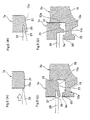
- FIG. 5 illustrates a second example of an embodiment of the present invention.
- performing the work of forming the engagement protrusions 11b around the circumferential edges of the large-diameter sections 21 of the support hole 13a of the retainer plate 7a is divided into two steps.
- a first punch 26 that is wedge shaped on the tip end is pressed against the circumferential edges of the large-diameter sections 21 of the other side surface in the axial direction of the retainer plate 7a.
- V-shaped concave grooves 27 are formed in the edges of the large-diameter sections 21 so that the width dimension in the radial direction of the opening section on the other side surface in the axial direction of the retainer plate 7a is wide and the width dimension becomes narrow going toward the back.
- the portions further on the inside in the radial direction than the concave grooves 27 are plastically deformed to form raw engagement sections 28 that are further on the inside in the radial direction than the concave grooves 27.
- the first punch 26 is removed from the concave grooves 27, and as illustrated in FIG. 5C and FIG. 5D , a second punch 29 having a flat tip-end surface is pressed inside the concave grooves 27 and plastically deforms the raw engagement protrusions 28, which are the portions located further on the inside in the radial direction than the concave grooves 27, further inward in the radial direction. Then, at the same time as forming the engagement protrusions 11b, the engagement protrusions 11b are caused to engage with the engagement groove 12a that is provided on the outer ring 5a side.
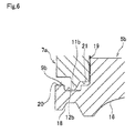
- FIG. 6 illustrates a third example of an embodiment of the present invention.
- an engagement groove 12b is provided around the entire middle section in the axial direction of a small-diameter stepped section 9b that is provided on the outer ring 5b side (portion except end section in the axial direction and base section in the axial direction of the small-diameter stepped section 9b).
- the thickness in the radial direction of the base section in the axial direction of the small-diameter stepped section 9b is maintained, and thus it is possible to improve the strength and rigidity of the portion on one end section in the axial direction of the outer ring 5b where the small-diameter stepped section 9b is formed.
- the other parts are the same as in the first example of an embodiment.
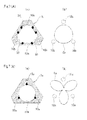
- FIG. 7A(a) is a schematic diagram for explaining a fourth example of an embodiment of the present invention.
- notches 30 that extend in the circumferential direction are formed in part of the inner-circumferential edge of a support hole 13b that is provided in the center section of a retainer plate 7b in portions where the phase in the circumferential direction coincides with that of mounting holes 10b.
- the diameter R 30 of the circumscribed circle of these notches 30 is greater than the outer diameter D (see FIG. 8 ) of the outer-circumferential surface of the outer ring 5a (portion of the outer ring 5a that is adjacent in the axial direction to the small-diameter stepped section 9a) (D ⁇ R 30 ).
- the side surface of the retainer plate 7b and the step surface 19 (see FIG. 8 ) that is located on the outer-circumferential surface of the outer ring 5a come in contact only in the portions between the notches 30, and do not come in contact in the portions where the notches 30 are formed.
- the portions close to the inner diameter of the one side surface in the axial direction of the retainer plate 7b and the step surface 19 only engage with the portions where the phase in the circumferential direction differs from that of the mounting holes 10b.
- plural large-diameter sections and engagement protrusions (all are omitted in the figures) that are provided around the inner-circumferential edge of the support hole 13b are formed in portions that are separated from the notches 30 in the circumferential direction.
- the notches 30 as large-diameter sections.
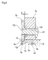
- the outer ring 5a fits inside a concave retaining section 4a of the housing 2a, and the surface on the end in the axial direction of the outer ring 5a is brought into contact with the surface of the back end of the concave retaining section 4a. Moreover, the portion close to the inner diameter of the one side surface in the axial direction of the retainer plate 7b (surface on the right side in FIG. 8 ) is brought into contact with the step surface 19 that is formed on the outer-circumferential surface of the outer ring 5a. In this state, there is a gap ⁇ between one surface in the axial direction of the housing 2a (surface on the left side in FIG. 8 ) and the one side surface in the axial direction of the retainer plate 7b. This gap is necessary for supporting the outer ring 5a by the housing 2a by tightening bolts 31 so that there is no looseness.
- the gap ⁇ is eliminated by inserting bolts 31 into through holes 32 that are provided in the housing 21, and then screwing the bolts into the mounting holes 10b and tightening.
- the step surface 19 is pressed by the portion close to the inner diameter of the one side surface in the axial direction of the retainer plate 7b, however, the force by which the step surface 19 is pressed is not uniform in the circumferential direction.
- FIG. 7B(a) when using a retainer plate 7a in which a simple circular support hole 13a is used, the force by which the step surface 19 is pressed becomes stronger in portions indicated by the black dots in FIG.
- the portion close to the inner diameter of the side surface in the axial direction of the retainer plate 7b strongly presses the step surface 19 by the portions that are separated in the circumferential direction from the mounting holes 10b as indicated by the black dots in FIG. 7A(a) due to the existence of the notches 30.
- the number of locations that are strongly pressed becomes double that of the mounting holes 10b (6 locations).
- the distribution of the force by which the step surface 19 is pressed becomes nearly uniform, and the worsening of the roundness of the outer ring 5a due to tightening of the bolts 31 is lessened. Consequently, as illustrated in FIG.
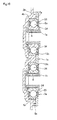
- FIG. 9 and FIG. 10 illustrate a fifth example of an embodiment of the present invention.
- plural support holes 13c (two locations in the example in the figures) are provided in one retainer plate 7c.
- Outer rings 5a are assembled on the inner side of each of the support holes 13c such that a little relative displacement in the radial direction of the support holes 13c is possible.
- the radial rolling bearing 3a respectively provided with the outer rings 5a support the tip ends of separate rotating shafts 1a, 1b so as to be able to rotate freely with respect to the housing 2b.
- the retainer plate is not able to rotate with respect to the outer rings 5a, however, it is possible to absorb shifting between the pitch of the support holes 13c, and the pitch of concave support sections 4b that are provided in the housing 2b.
- the outer rings 5a are fitted so there is no looseness by fitting the outer rings 5a in the concave support sections 4b with a light interference fit, and when assembling the outer rings 5a on the inside of the support holes 13c so that relative displacement is not possible in the radial direction, it is necessary for the pitch of the support holes 13c to coincide exactly.
- the rolling bearing unit with retainer plate of the present invention can be suitably applied to the case of rotatably supporting the end section of a rotating shaft on the inside surface of a housing in an automobile transmission that includes both a manual transmission and automatic transmission.
Landscapes
- Engineering & Computer Science (AREA)
- General Engineering & Computer Science (AREA)
- Mechanical Engineering (AREA)
- Rolling Contact Bearings (AREA)
- Mounting Of Bearings Or Others (AREA)
Applications Claiming Priority (3)
| Application Number | Priority Date | Filing Date | Title |
|---|---|---|---|
| JP2012146398 | 2012-06-29 | ||
| JP2012181681A JP6003392B2 (ja) | 2012-06-29 | 2012-08-20 | 取付板付転がり軸受ユニットとその製造方法 |
| PCT/JP2013/067737 WO2014003149A1 (ja) | 2012-06-29 | 2013-06-27 | 取付板付き転がり軸受ユニットおよびその製造方法 |
Publications (3)
| Publication Number | Publication Date |
|---|---|
| EP2853762A1 true EP2853762A1 (de) | 2015-04-01 |
| EP2853762A4 EP2853762A4 (de) | 2016-03-09 |
| EP2853762B1 EP2853762B1 (de) | 2018-01-03 |
Family
ID=49783284
Family Applications (1)
| Application Number | Title | Priority Date | Filing Date |
|---|---|---|---|
| EP13810076.3A Active EP2853762B1 (de) | 2012-06-29 | 2013-06-27 | Wälzlagereinheit mit montageplatte und verfahren zur herstellung davon |
Country Status (4)
| Country | Link |
|---|---|
| EP (1) | EP2853762B1 (de) |
| JP (1) | JP6003392B2 (de) |
| CN (2) | CN104395628B (de) |
| WO (1) | WO2014003149A1 (de) |
Cited By (2)
| Publication number | Priority date | Publication date | Assignee | Title |
|---|---|---|---|---|
| US10060472B2 (en) * | 2014-06-13 | 2018-08-28 | Nsk Ltd. | Bearing device and method for manufacturing bearing device |
| US11105375B2 (en) | 2020-01-09 | 2021-08-31 | Caterpillar Inc. | Retention system for bearing member |
Families Citing this family (6)
| Publication number | Priority date | Publication date | Assignee | Title |
|---|---|---|---|---|
| JP6349762B2 (ja) * | 2014-02-12 | 2018-07-04 | 日本精工株式会社 | 軸受装置及び軸受装置の製造方法 |
| JP6561523B2 (ja) * | 2014-05-27 | 2019-08-21 | 日本精工株式会社 | 軸受装置及び軸受装置用固定プレート |
| US9903416B2 (en) | 2014-08-27 | 2018-02-27 | Nsk Ltd. | Bearing device and method for manufacturing bearing device |
| JP6597002B2 (ja) | 2015-07-14 | 2019-10-30 | 日本精工株式会社 | 軸受装置及び軸受装置の製造方法 |
| WO2017170034A1 (ja) * | 2016-03-30 | 2017-10-05 | Ntn株式会社 | 転がり軸受装置及びプレート一体型転がり軸受 |
| DE102018119256B4 (de) * | 2017-09-05 | 2024-03-14 | Schaeffler Technologies AG & Co. KG | Lagereinheit |
Family Cites Families (13)
| Publication number | Priority date | Publication date | Assignee | Title |
|---|---|---|---|---|
| DE2611218A1 (de) * | 1976-03-17 | 1977-10-06 | Kugelfischer G Schaefer & Co | Form- und kraftschluessige verbindung von waelzlagerteilen mit umgebungsteilen |
| JP2000074079A (ja) * | 1998-06-17 | 2000-03-07 | Nippon Seiko Kk | フランジ付転がり軸受 |
| JP2005308135A (ja) * | 2004-04-23 | 2005-11-04 | Koyo Seiko Co Ltd | ころ軸受用の溶接保持器、ならびにこの溶接保持器の製造方法 |
| DE102004031830B4 (de) * | 2004-07-01 | 2012-06-21 | Ab Skf | Verfahren zur Herstellung einer Lageranordnung |
| DE102004053078B4 (de) * | 2004-11-03 | 2008-07-10 | Ab Skf | Lageranordung |
| JP2007247857A (ja) * | 2006-03-17 | 2007-09-27 | Ntn Corp | 歯車用軸受装置 |
| CN100412396C (zh) * | 2006-12-20 | 2008-08-20 | 常熟长城轴承有限公司 | 滚针轴承 |
| JP4877044B2 (ja) | 2007-04-25 | 2012-02-15 | 日本精工株式会社 | 軸受装置および軸受装置の組立方法 |
| JP5136010B2 (ja) * | 2007-06-22 | 2013-02-06 | 日本精工株式会社 | 回転支持装置及び回転支持装置用転がり軸受ユニット |
| JP4752817B2 (ja) * | 2007-07-04 | 2011-08-17 | 日本精工株式会社 | 軸受装置および軸受装置の組立方法 |
| JP4877135B2 (ja) | 2007-08-02 | 2012-02-15 | 日本精工株式会社 | 軸受装置および軸受装置の組立方法 |
| DE102008021832B3 (de) * | 2008-04-30 | 2009-08-20 | Ab Skf | Verfahren zur Herstellung eines Lagerträgers für ein Lager und Lageranordnung mit einem solchen Lagerträger |
| DE102009001359A1 (de) * | 2009-03-05 | 2010-09-09 | Zf Lenksysteme Gmbh | Flügelzellenpumpe |
-
2012
- 2012-08-20 JP JP2012181681A patent/JP6003392B2/ja active Active
-
2013
- 2013-06-27 CN CN201380034622.XA patent/CN104395628B/zh active Active
- 2013-06-27 WO PCT/JP2013/067737 patent/WO2014003149A1/ja active Application Filing
- 2013-06-27 EP EP13810076.3A patent/EP2853762B1/de active Active
- 2013-06-27 CN CN201710052347.4A patent/CN106555816B/zh active Active
Cited By (2)
| Publication number | Priority date | Publication date | Assignee | Title |
|---|---|---|---|---|
| US10060472B2 (en) * | 2014-06-13 | 2018-08-28 | Nsk Ltd. | Bearing device and method for manufacturing bearing device |
| US11105375B2 (en) | 2020-01-09 | 2021-08-31 | Caterpillar Inc. | Retention system for bearing member |
Also Published As
| Publication number | Publication date |
|---|---|
| JP2014029196A (ja) | 2014-02-13 |
| WO2014003149A1 (ja) | 2014-01-03 |
| CN106555816B (zh) | 2021-04-13 |
| JP6003392B2 (ja) | 2016-10-05 |
| CN104395628A (zh) | 2015-03-04 |
| CN106555816A (zh) | 2017-04-05 |
| CN104395628B (zh) | 2017-06-23 |
| EP2853762A4 (de) | 2016-03-09 |
| EP2853762B1 (de) | 2018-01-03 |
Similar Documents
| Publication | Publication Date | Title |
|---|---|---|
| EP2853762B1 (de) | Wälzlagereinheit mit montageplatte und verfahren zur herstellung davon | |
| US9624977B2 (en) | Cylindrical roller bearing | |
| US9308777B2 (en) | Bearing device for a wheel | |
| EP2746605B1 (de) | Montageverfahren für Lagereinheit | |
| US20130089285A1 (en) | Tapered roller bearing | |
| EP1747383A1 (de) | Konusverschluss-lageranordnung | |
| EP2565051B1 (de) | Radlagervorrichtung | |
| EP1961981A1 (de) | Lagervorrichtung für rad | |
| EP3054184B1 (de) | Zweireihige kegelrollenlagereinheit und verfahren zur herstellung der lagereinheit | |
| EP2963306B1 (de) | Vorläufiger halter für radialnadellager | |
| EP2351939B1 (de) | Käfigrollen | |
| JP6597002B2 (ja) | 軸受装置及び軸受装置の製造方法 | |
| JP2014029197A (ja) | 取付板付転がり軸受ユニットとその製造方法 | |
| US20080273824A1 (en) | Bearing device for axle and fixing structure using the same | |
| EP2172664A1 (de) | Stiftartiger halter, verfahren zur anbringung von kugeln an dem stiftartigen halter und kugellager | |
| JP7201025B2 (ja) | ハブユニット軸受及び車両 | |
| JP6332520B2 (ja) | 取付板付転がり軸受ユニット | |
| KR20200029496A (ko) | 구름 베어링 및 보유 지지기 | |
| WO2021235021A1 (ja) | 自動調心ころ軸受用保持器の製造方法 | |
| EP1889734B1 (de) | Achslagervorrichtung und Verfahren zur Herstellung einer Nabenwelle für eine Antriebsradlagervorrichtung | |
| JP2013117298A (ja) | リテーナープレート付き軸受ユニット | |
| US10533607B2 (en) | Cage for radial roller bearing | |
| KR101484142B1 (ko) | 자동차의 휠 베어링 | |
| JP2008281018A (ja) | 円筒ころ軸受用保持器 |
Legal Events
| Date | Code | Title | Description |
|---|---|---|---|
| PUAI | Public reference made under article 153(3) epc to a published international application that has entered the european phase |
Free format text: ORIGINAL CODE: 0009012 |
|
| 17P | Request for examination filed |
Effective date: 20141222 |
|
| AK | Designated contracting states |
Kind code of ref document: A1 Designated state(s): AL AT BE BG CH CY CZ DE DK EE ES FI FR GB GR HR HU IE IS IT LI LT LU LV MC MK MT NL NO PL PT RO RS SE SI SK SM TR |
|
| AX | Request for extension of the european patent |
Extension state: BA ME |
|
| DAX | Request for extension of the european patent (deleted) | ||
| RA4 | Supplementary search report drawn up and despatched (corrected) |
Effective date: 20160210 |
|
| RIC1 | Information provided on ipc code assigned before grant |
Ipc: F16C 35/067 20060101AFI20160204BHEP Ipc: F16C 19/06 20060101ALN20160204BHEP Ipc: F16C 33/58 20060101ALI20160204BHEP Ipc: F16C 19/54 20060101ALN20160204BHEP |
|
| GRAP | Despatch of communication of intention to grant a patent |
Free format text: ORIGINAL CODE: EPIDOSNIGR1 |
|
| RIC1 | Information provided on ipc code assigned before grant |
Ipc: F16C 35/067 20060101AFI20170703BHEP Ipc: F16C 19/06 20060101ALN20170703BHEP Ipc: F16C 33/58 20060101ALI20170703BHEP Ipc: F16C 19/54 20060101ALN20170703BHEP |
|
| RIC1 | Information provided on ipc code assigned before grant |
Ipc: F16C 19/06 20060101ALN20170707BHEP Ipc: F16C 19/54 20060101ALN20170707BHEP Ipc: F16C 33/58 20060101ALI20170707BHEP Ipc: F16C 35/067 20060101AFI20170707BHEP Ipc: F16C 35/04 20060101ALI20170707BHEP |
|
| INTG | Intention to grant announced |
Effective date: 20170803 |
|
| GRAS | Grant fee paid |
Free format text: ORIGINAL CODE: EPIDOSNIGR3 |
|
| GRAA | (expected) grant |
Free format text: ORIGINAL CODE: 0009210 |
|
| AK | Designated contracting states |
Kind code of ref document: B1 Designated state(s): AL AT BE BG CH CY CZ DE DK EE ES FI FR GB GR HR HU IE IS IT LI LT LU LV MC MK MT NL NO PL PT RO RS SE SI SK SM TR |
|
| REG | Reference to a national code |
Ref country code: GB Ref legal event code: FG4D |
|
| REG | Reference to a national code |
Ref country code: CH Ref legal event code: EP Ref country code: AT Ref legal event code: REF Ref document number: 960566 Country of ref document: AT Kind code of ref document: T Effective date: 20180115 |
|
| REG | Reference to a national code |
Ref country code: IE Ref legal event code: FG4D |
|
| REG | Reference to a national code |
Ref country code: DE Ref legal event code: R096 Ref document number: 602013031739 Country of ref document: DE |
|
| REG | Reference to a national code |
Ref country code: NL Ref legal event code: MP Effective date: 20180103 |
|
| REG | Reference to a national code |
Ref country code: LT Ref legal event code: MG4D |
|
| REG | Reference to a national code |
Ref country code: AT Ref legal event code: MK05 Ref document number: 960566 Country of ref document: AT Kind code of ref document: T Effective date: 20180103 |
|
| PG25 | Lapsed in a contracting state [announced via postgrant information from national office to epo] |
Ref country code: NL Free format text: LAPSE BECAUSE OF FAILURE TO SUBMIT A TRANSLATION OF THE DESCRIPTION OR TO PAY THE FEE WITHIN THE PRESCRIBED TIME-LIMIT Effective date: 20180103 |
|
| PG25 | Lapsed in a contracting state [announced via postgrant information from national office to epo] |
Ref country code: ES Free format text: LAPSE BECAUSE OF FAILURE TO SUBMIT A TRANSLATION OF THE DESCRIPTION OR TO PAY THE FEE WITHIN THE PRESCRIBED TIME-LIMIT Effective date: 20180103 Ref country code: NO Free format text: LAPSE BECAUSE OF FAILURE TO SUBMIT A TRANSLATION OF THE DESCRIPTION OR TO PAY THE FEE WITHIN THE PRESCRIBED TIME-LIMIT Effective date: 20180403 Ref country code: LT Free format text: LAPSE BECAUSE OF FAILURE TO SUBMIT A TRANSLATION OF THE DESCRIPTION OR TO PAY THE FEE WITHIN THE PRESCRIBED TIME-LIMIT Effective date: 20180103 Ref country code: CY Free format text: LAPSE BECAUSE OF FAILURE TO SUBMIT A TRANSLATION OF THE DESCRIPTION OR TO PAY THE FEE WITHIN THE PRESCRIBED TIME-LIMIT Effective date: 20180103 Ref country code: FI Free format text: LAPSE BECAUSE OF FAILURE TO SUBMIT A TRANSLATION OF THE DESCRIPTION OR TO PAY THE FEE WITHIN THE PRESCRIBED TIME-LIMIT Effective date: 20180103 Ref country code: HR Free format text: LAPSE BECAUSE OF FAILURE TO SUBMIT A TRANSLATION OF THE DESCRIPTION OR TO PAY THE FEE WITHIN THE PRESCRIBED TIME-LIMIT Effective date: 20180103 |
|
| PG25 | Lapsed in a contracting state [announced via postgrant information from national office to epo] |
Ref country code: BG Free format text: LAPSE BECAUSE OF FAILURE TO SUBMIT A TRANSLATION OF THE DESCRIPTION OR TO PAY THE FEE WITHIN THE PRESCRIBED TIME-LIMIT Effective date: 20180403 Ref country code: GR Free format text: LAPSE BECAUSE OF FAILURE TO SUBMIT A TRANSLATION OF THE DESCRIPTION OR TO PAY THE FEE WITHIN THE PRESCRIBED TIME-LIMIT Effective date: 20180404 Ref country code: IS Free format text: LAPSE BECAUSE OF FAILURE TO SUBMIT A TRANSLATION OF THE DESCRIPTION OR TO PAY THE FEE WITHIN THE PRESCRIBED TIME-LIMIT Effective date: 20180503 Ref country code: LV Free format text: LAPSE BECAUSE OF FAILURE TO SUBMIT A TRANSLATION OF THE DESCRIPTION OR TO PAY THE FEE WITHIN THE PRESCRIBED TIME-LIMIT Effective date: 20180103 Ref country code: SE Free format text: LAPSE BECAUSE OF FAILURE TO SUBMIT A TRANSLATION OF THE DESCRIPTION OR TO PAY THE FEE WITHIN THE PRESCRIBED TIME-LIMIT Effective date: 20180103 Ref country code: PL Free format text: LAPSE BECAUSE OF FAILURE TO SUBMIT A TRANSLATION OF THE DESCRIPTION OR TO PAY THE FEE WITHIN THE PRESCRIBED TIME-LIMIT Effective date: 20180103 Ref country code: RS Free format text: LAPSE BECAUSE OF FAILURE TO SUBMIT A TRANSLATION OF THE DESCRIPTION OR TO PAY THE FEE WITHIN THE PRESCRIBED TIME-LIMIT Effective date: 20180103 Ref country code: AT Free format text: LAPSE BECAUSE OF FAILURE TO SUBMIT A TRANSLATION OF THE DESCRIPTION OR TO PAY THE FEE WITHIN THE PRESCRIBED TIME-LIMIT Effective date: 20180103 |
|
| REG | Reference to a national code |
Ref country code: DE Ref legal event code: R097 Ref document number: 602013031739 Country of ref document: DE |
|
| PG25 | Lapsed in a contracting state [announced via postgrant information from national office to epo] |
Ref country code: RO Free format text: LAPSE BECAUSE OF FAILURE TO SUBMIT A TRANSLATION OF THE DESCRIPTION OR TO PAY THE FEE WITHIN THE PRESCRIBED TIME-LIMIT Effective date: 20180103 Ref country code: EE Free format text: LAPSE BECAUSE OF FAILURE TO SUBMIT A TRANSLATION OF THE DESCRIPTION OR TO PAY THE FEE WITHIN THE PRESCRIBED TIME-LIMIT Effective date: 20180103 Ref country code: IT Free format text: LAPSE BECAUSE OF FAILURE TO SUBMIT A TRANSLATION OF THE DESCRIPTION OR TO PAY THE FEE WITHIN THE PRESCRIBED TIME-LIMIT Effective date: 20180103 Ref country code: AL Free format text: LAPSE BECAUSE OF FAILURE TO SUBMIT A TRANSLATION OF THE DESCRIPTION OR TO PAY THE FEE WITHIN THE PRESCRIBED TIME-LIMIT Effective date: 20180103 |
|
| PLBE | No opposition filed within time limit |
Free format text: ORIGINAL CODE: 0009261 |
|
| STAA | Information on the status of an ep patent application or granted ep patent |
Free format text: STATUS: NO OPPOSITION FILED WITHIN TIME LIMIT |
|
| PG25 | Lapsed in a contracting state [announced via postgrant information from national office to epo] |
Ref country code: DK Free format text: LAPSE BECAUSE OF FAILURE TO SUBMIT A TRANSLATION OF THE DESCRIPTION OR TO PAY THE FEE WITHIN THE PRESCRIBED TIME-LIMIT Effective date: 20180103 Ref country code: SK Free format text: LAPSE BECAUSE OF FAILURE TO SUBMIT A TRANSLATION OF THE DESCRIPTION OR TO PAY THE FEE WITHIN THE PRESCRIBED TIME-LIMIT Effective date: 20180103 Ref country code: CZ Free format text: LAPSE BECAUSE OF FAILURE TO SUBMIT A TRANSLATION OF THE DESCRIPTION OR TO PAY THE FEE WITHIN THE PRESCRIBED TIME-LIMIT Effective date: 20180103 Ref country code: SM Free format text: LAPSE BECAUSE OF FAILURE TO SUBMIT A TRANSLATION OF THE DESCRIPTION OR TO PAY THE FEE WITHIN THE PRESCRIBED TIME-LIMIT Effective date: 20180103 |
|
| 26N | No opposition filed |
Effective date: 20181005 |
|
| REG | Reference to a national code |
Ref country code: CH Ref legal event code: PL |
|
| PG25 | Lapsed in a contracting state [announced via postgrant information from national office to epo] |
Ref country code: SI Free format text: LAPSE BECAUSE OF FAILURE TO SUBMIT A TRANSLATION OF THE DESCRIPTION OR TO PAY THE FEE WITHIN THE PRESCRIBED TIME-LIMIT Effective date: 20180103 |
|
| REG | Reference to a national code |
Ref country code: BE Ref legal event code: MM Effective date: 20180630 |
|
| PG25 | Lapsed in a contracting state [announced via postgrant information from national office to epo] |
Ref country code: LU Free format text: LAPSE BECAUSE OF NON-PAYMENT OF DUE FEES Effective date: 20180627 Ref country code: MC Free format text: LAPSE BECAUSE OF FAILURE TO SUBMIT A TRANSLATION OF THE DESCRIPTION OR TO PAY THE FEE WITHIN THE PRESCRIBED TIME-LIMIT Effective date: 20180103 |
|
| REG | Reference to a national code |
Ref country code: IE Ref legal event code: MM4A |
|
| PG25 | Lapsed in a contracting state [announced via postgrant information from national office to epo] |
Ref country code: FR Free format text: LAPSE BECAUSE OF NON-PAYMENT OF DUE FEES Effective date: 20180630 Ref country code: CH Free format text: LAPSE BECAUSE OF NON-PAYMENT OF DUE FEES Effective date: 20180630 Ref country code: IE Free format text: LAPSE BECAUSE OF NON-PAYMENT OF DUE FEES Effective date: 20180627 Ref country code: LI Free format text: LAPSE BECAUSE OF NON-PAYMENT OF DUE FEES Effective date: 20180630 |
|
| PG25 | Lapsed in a contracting state [announced via postgrant information from national office to epo] |
Ref country code: BE Free format text: LAPSE BECAUSE OF NON-PAYMENT OF DUE FEES Effective date: 20180630 |
|
| PG25 | Lapsed in a contracting state [announced via postgrant information from national office to epo] |
Ref country code: MT Free format text: LAPSE BECAUSE OF NON-PAYMENT OF DUE FEES Effective date: 20180627 |
|
| PG25 | Lapsed in a contracting state [announced via postgrant information from national office to epo] |
Ref country code: TR Free format text: LAPSE BECAUSE OF FAILURE TO SUBMIT A TRANSLATION OF THE DESCRIPTION OR TO PAY THE FEE WITHIN THE PRESCRIBED TIME-LIMIT Effective date: 20180103 |
|
| PG25 | Lapsed in a contracting state [announced via postgrant information from national office to epo] |
Ref country code: PT Free format text: LAPSE BECAUSE OF FAILURE TO SUBMIT A TRANSLATION OF THE DESCRIPTION OR TO PAY THE FEE WITHIN THE PRESCRIBED TIME-LIMIT Effective date: 20180103 Ref country code: HU Free format text: LAPSE BECAUSE OF FAILURE TO SUBMIT A TRANSLATION OF THE DESCRIPTION OR TO PAY THE FEE WITHIN THE PRESCRIBED TIME-LIMIT; INVALID AB INITIO Effective date: 20130627 |
|
| PG25 | Lapsed in a contracting state [announced via postgrant information from national office to epo] |
Ref country code: MK Free format text: LAPSE BECAUSE OF NON-PAYMENT OF DUE FEES Effective date: 20180103 |
|
| PGFP | Annual fee paid to national office [announced via postgrant information from national office to epo] |
Ref country code: GB Payment date: 20240509 Year of fee payment: 12 |
|
| PGFP | Annual fee paid to national office [announced via postgrant information from national office to epo] |
Ref country code: DE Payment date: 20240502 Year of fee payment: 12 |