EP2853331A2 - Vorrichtung und Verfahren zum Herstellen eines Zahnrads - Google Patents
Vorrichtung und Verfahren zum Herstellen eines Zahnrads Download PDFInfo
- Publication number
- EP2853331A2 EP2853331A2 EP14185886.0A EP14185886A EP2853331A2 EP 2853331 A2 EP2853331 A2 EP 2853331A2 EP 14185886 A EP14185886 A EP 14185886A EP 2853331 A2 EP2853331 A2 EP 2853331A2
- Authority
- EP
- European Patent Office
- Prior art keywords
- work
- cutter
- correction
- cutting
- vibration
- Prior art date
- Legal status (The legal status is an assumption and is not a legal conclusion. Google has not performed a legal analysis and makes no representation as to the accuracy of the status listed.)
- Withdrawn
Links
Images




Classifications
-
- G—PHYSICS
- G05—CONTROLLING; REGULATING
- G05B—CONTROL OR REGULATING SYSTEMS IN GENERAL; FUNCTIONAL ELEMENTS OF SUCH SYSTEMS; MONITORING OR TESTING ARRANGEMENTS FOR SUCH SYSTEMS OR ELEMENTS
- G05B19/00—Program-control systems
- G05B19/02—Program-control systems electric
- G05B19/18—Numerical control [NC], i.e. automatically operating machines, in particular machine tools, e.g. in a manufacturing environment, so as to execute positioning, movement or co-ordinated operations by means of program data in numerical form
- G05B19/182—Numerical control [NC], i.e. automatically operating machines, in particular machine tools, e.g. in a manufacturing environment, so as to execute positioning, movement or co-ordinated operations by means of program data in numerical form characterised by the machine tool function, e.g. thread cutting, cam making, tool direction control
- G05B19/186—Generation of screw- or gearlike surfaces
-
- B—PERFORMING OPERATIONS; TRANSPORTING
- B23—MACHINE TOOLS; METAL-WORKING NOT OTHERWISE PROVIDED FOR
- B23F—MAKING GEARS OR TOOTHED RACKS
- B23F5/00—Making straight gear teeth involving moving a tool relatively to a workpiece with a rolling-off or an enveloping motion with respect to the gear teeth to be made
- B23F5/12—Making straight gear teeth involving moving a tool relatively to a workpiece with a rolling-off or an enveloping motion with respect to the gear teeth to be made by planing or slotting
- B23F5/16—Making straight gear teeth involving moving a tool relatively to a workpiece with a rolling-off or an enveloping motion with respect to the gear teeth to be made by planing or slotting the tool having a shape similar to that of a spur wheel or part thereof
- B23F5/163—Making straight gear teeth involving moving a tool relatively to a workpiece with a rolling-off or an enveloping motion with respect to the gear teeth to be made by planing or slotting the tool having a shape similar to that of a spur wheel or part thereof the tool and workpiece being in crossed axis arrangement, e.g. skiving, i.e. "Waelzschaelen"
-
- B—PERFORMING OPERATIONS; TRANSPORTING
- B23—MACHINE TOOLS; METAL-WORKING NOT OTHERWISE PROVIDED FOR
- B23F—MAKING GEARS OR TOOTHED RACKS
- B23F23/00—Accessories or equipment combined with or arranged in, or specially designed to form part of, gear-cutting machines
- B23F23/006—Equipment for synchronising movement of cutting tool and workpiece, the cutting tool and workpiece not being mechanically coupled
-
- B—PERFORMING OPERATIONS; TRANSPORTING
- B23—MACHINE TOOLS; METAL-WORKING NOT OTHERWISE PROVIDED FOR
- B23F—MAKING GEARS OR TOOTHED RACKS
- B23F23/00—Accessories or equipment combined with or arranged in, or specially designed to form part of, gear-cutting machines
- B23F23/10—Arrangements for compensating irregularities in drives or indexing mechanisms
-
- B—PERFORMING OPERATIONS; TRANSPORTING
- B23—MACHINE TOOLS; METAL-WORKING NOT OTHERWISE PROVIDED FOR
- B23F—MAKING GEARS OR TOOTHED RACKS
- B23F23/00—Accessories or equipment combined with or arranged in, or specially designed to form part of, gear-cutting machines
- B23F23/12—Other devices, e.g. tool holders; Checking devices for controlling workpieces in machines for manufacturing gear teeth
-
- B—PERFORMING OPERATIONS; TRANSPORTING
- B23—MACHINE TOOLS; METAL-WORKING NOT OTHERWISE PROVIDED FOR
- B23Q—DETAILS, COMPONENTS, OR ACCESSORIES FOR MACHINE TOOLS, e.g. ARRANGEMENTS FOR COPYING OR CONTROLLING; MACHINE TOOLS IN GENERAL CHARACTERISED BY THE CONSTRUCTION OF PARTICULAR DETAILS OR COMPONENTS; COMBINATIONS OR ASSOCIATIONS OF METAL-WORKING MACHINES, NOT DIRECTED TO A PARTICULAR RESULT
- B23Q15/00—Automatic control or regulation of feed movement, cutting velocity or position of tool or work
- B23Q15/007—Automatic control or regulation of feed movement, cutting velocity or position of tool or work while the tool acts upon the workpiece
- B23Q15/12—Adaptive control, i.e. adjusting itself to have a performance which is optimum according to a preassigned criterion
-
- B—PERFORMING OPERATIONS; TRANSPORTING
- B23—MACHINE TOOLS; METAL-WORKING NOT OTHERWISE PROVIDED FOR
- B23Q—DETAILS, COMPONENTS, OR ACCESSORIES FOR MACHINE TOOLS, e.g. ARRANGEMENTS FOR COPYING OR CONTROLLING; MACHINE TOOLS IN GENERAL CHARACTERISED BY THE CONSTRUCTION OF PARTICULAR DETAILS OR COMPONENTS; COMBINATIONS OR ASSOCIATIONS OF METAL-WORKING MACHINES, NOT DIRECTED TO A PARTICULAR RESULT
- B23Q17/00—Arrangements for observing, indicating or measuring on machine tools
- B23Q17/12—Arrangements for observing, indicating or measuring on machine tools for indicating or measuring vibration
-
- G—PHYSICS
- G05—CONTROLLING; REGULATING
- G05B—CONTROL OR REGULATING SYSTEMS IN GENERAL; FUNCTIONAL ELEMENTS OF SUCH SYSTEMS; MONITORING OR TESTING ARRANGEMENTS FOR SUCH SYSTEMS OR ELEMENTS
- G05B2219/00—Program-control systems
- G05B2219/30—Nc systems
- G05B2219/36—Nc in input of data, input key till input tape
- G05B2219/36198—Gear, thread cutting
Definitions
- This disclosure generally relates to a gear manufacturing device and a method for manufacturing a gear.
- Patent reference 1 JP2012-45687A discloses a gear cutting machining performed by feeding a skiving cutter (pinion cutter according to Patent reference 1), which synchronously rotates with a ring-shaped work, in a direction of a tooth trace of a tooth that is produced on the work while rotating the work.
- machining is performed efficiently or fast by synchronously rotating the work and the skiving cutter.
- skiving is disclosed in the following reference: KOJIMA Masakazu, and NISHIJIMA Komio. "Study in Skiving of Internal Spur Gear: Part 1, On Cutter Profile” Transactions of the Japan Society of Mechanical Engineers (edition C) 39(324), 2580-2586 , (hereinafter referred to as non-patent reference 1). As disclosed in non-patent reference 1, the skiving is a type of machining in which cutting is achieved using "sliding, or sliding action.”
- the cutting is performed using the "sliding, or sliding action" in which a blade portion of a pinion cutter relatively moves in a direction of a tooth trace of a tooth produced on a work by synchronously rotating the work and the pinion cutter in a manner that the blade portion of the pinion cutter meshes with the tooth at a tooth space to be formed on the work by cutting, which enables a fast speed, or efficient machining.
- vibrations may occur at (in) the end of the cutting by the cutter.
- the vibration is generated, because a positional relationship between the cutter and the work is displaced, or shifted, a tooth surface of the work is excessively cut and a width of the tooth space of the machining region where the vibration is generated is expanded.
- a rotation axis of the work and a rotation axis of the cutter are positioned skew.
- a preceding side downstream side of rotation
- a following side upstream side of rotation
- the leading side of the blade portion is disengaged (released) from the work first
- the trailing side is disengaged (released) from the work later at the completion of the cutting.
- the vibration is unlikely generated due to stable load applied to the pinion cutter because the load is equally applied to the leading side and the trailing side of a cutting edge in a state where the cutting continues after starting the cutting.
- the vibration may be generated at a timing when the leading side of the blade portion is disengaged (released) from the work at a terminal end of the cut region, or a portion close to a terminal end of the cut region.
- the cutter is support at (by) one side (cantilever structure) relative to an axial end of a drive shaft, which is readily vibrated, thus the vibration may readily occur.
- a diameter of the drive shaft of the pinion cutter may be increased.
- a gear manufacturing device includes a control unit for synchronously rotating a work rotatably supported about a work axis and a cutter formed in a gear shape and rotatably supported about a cutter axis, the work axis and the cutter axis being skew to each other, the control unit relatively moving the cutter and the work in an axial direction of the work with a predetermined cutting depth.
- the gear manufacturing device further includes a vibration sensor detecting a vibration of the work and the cutter, and a correction control portion executing at least one of a position correction and a phase correction when an amplitude value of a vibration detected by the vibration sensor during a machining reaches equal to or greater than a set value, the position correction for correcting a relative positional relationship of the cutter and the work in a direction to correct the cutting depth, the phase correction for correcting a relative phase of the cutter and the work in a direction to correct an unbalance cutting that is otherwise to be applied on a pair of tooth surfaces that structure a tooth portion formed on the work.
- the correction control portion executes at least one of the position correction for correcting the relative positional relationship of the cutter and the work in a direction to reduce the cutting depth and the phase correction for correcting the relative phase of the cutter and the work in a direction to correct an unbalance cutting that is otherwise to be applied on the tooth surfaces serving as a pair that structure the tooth portion formed on the work in a case where the vibration sensor detects a vibration with an amplitude equal to or greater than the set value (predetermined value) during the cutting of the work by the cutter.
- the excessive cutting at one of the tooth surfaces can be restrained. It is considered that a firm contact of the work and the cutter causes the unbalance cutting of the tooth surfaces of the tooth portion serving as a pair.
- the phase correction the firm contact of the work and the cutter can be canceled to restrain the vibration from occurring.
- the vibration is restrained to enhance the machining precision when manufacturing a gear by skiving, and thus a gear manufacturing device for manufacturing a gear with high precision can be attained.
- the correction control portion obtains the amplitude value of the vibration from a detection signal of the vibration sensor, and sets a correction amount of the position correction and the phase correction on the basis of an arithmetic operation based on the amplitude value.
- the correction control portion when the amplitude value of the vibration detected by the vibration sensor reaches equal to or greater than the set value (predetermined value), the correction control portion obtains the correction amount by the arithmetic operation on the basis of the amplitude value, and at least one of the position correction and the phase correction is executed.
- the amplitude value of the vibration detected by the vibration sensor can be reflected on the correction amount of the correction, which allows an appropriate correction.
- the correction control portion includes a correction amount reference table which stores a correction amount related to the amplitude value detected by the vibration sensor and a correction amount read out portion reading out the correction amount of said at least one of the position correction and the phase correction from the correction amount reference table on the basis of the amplitude value from the detection signal of the vibration sensor.
- the correction amount read out portion reads out the correction value from the correction amount reference table, and at least one of the position correction and the phase correction is executed.
- the gear manufacturing device further includes an alert control portion alerting an abnormality in a case where the amplitude value detected by the vibration sensor reaches equal to or greater than a predetermined limitation value.
- the gear manufacturing device further includes an alert control portion performing a replacing alert urging to replace the cutter in a case where the amplitude detected by the vibration sensor reaches equal to or greater than a predetermined reference value.
- the vibration caused during the machining, or skiving increases compared to the case where the cutter with appropriate cutting capacity is applied.
- alerting by the alert control portion is performed when the cutting capacity of the cutter is declined.
- the device alerts an operator to the situation where the replacing of the cutter is necessary, and urges the operator to appropriately respond.
- a method for manufacturing a gear includes synchronously rotating a work rotatably supported about a work axis and a cutter rotatably supported about a cutter axis, the work axis and the cutter axis being skew to each other, skiving the work by relatively moving the cutter and the work in an axial direction of the work with a predetermined cutting depth, and performing at least one of a position correction and a phase correction when an amplitude value of a vibration detected by a vibration sensor to which the vibration of the work or the cutter is transmitted during the skiving reaches equal to or greater than a set value, the position correction for correcting a relative positional relationship of the cutter and the work in a direction to correct the cutting depth, the phase correction for correcting a relative phase of the cutter and the work in a direction to correct an unbalance cutting that is otherwise to be applied on a pair of tooth surfaces that construct a tooth portion formed on the work.
- the vibration of the amplitude equal to or greater than the set value (predetermined value) is detected by the vibration sensor during the cutting of the work by the cutter, at least one of the position correction for correcting the relative positional relationship of the cutter and the work in a direction to reduce the cutting depth (shallower cutting depth) and the phase correction for correcting the relative phase of the cutter and the work in a direction to correct the unbalance cutting that is otherwise to be applied on the tooth surfaces (serving as a pair) of the tooth portion formed on the work is performed.
- the relative phase of the work and the cutter is corrected in a direction to correct the unbalance cutting that is otherwise to be applied on the tooth surfaces (serving as a pair) that structure the tooth portion formed on the work by the phase correction, the excessive cutting of one of the tooth surfaces can be restrained. It is considered that a firm contact of the work and the cutter causes the unbalance cutting of the tooth surfaces of the tooth portion serving as a pair. By cancelling the firm contact of the work and the cutter by the correction, the vibration can be restrained from occurring.
- the machining precision is enhanced by restraining the vibration when manufacturing a gear by the skiving, and a method for manufacturing a gear with high precision can be attained.
- the method for manufacturing the gear further includes storing a maximum amplitude value of the vibration detected by the vibration sensor when the work is processed with the cutting by the cutter and a cutting error value for a maximum cutting amount of each of the pair of tooth surfaces of the tooth portion formed on the work by the skiving when the vibration occurs, obtaining at least an amplitude ratio on the basis of the amplitude value that the vibration sensor detects and the maximum amplitude value, obtaining a correction amount by a correction amount computing portion on the basis of the amplitude ratio and the cutting error value, and executing at least one of the position correction and the phase correction on the basis of the correction amount.
- the correction amount computing portion obtains the correction amount on the basis of the maximum amplitude value and the cutting error value stored in a memory in advance and the amplitude value, and at least one of the position correction and the phase correction is performed.
- the amplitude value of the vibration detected by the vibration sensor is reflected on the correction amount of the correction, and thus the correction is appropriately performed.
- the method for manufacturing the gear further includes obtaining the maximum amplitude value of a vibration detected by the vibration sensor when the work is processed with the cutting by the cutter, obtaining the cutting error value for a maximum cutting amount of each of the pair of tooth surfaces of the tooth portion formed on the work by skiving when the vibration occurs, obtaining the plural amplitude ratios on the basis of the maximum amplitude value and a predicted amplitude value that is predicted to be detected by the vibration sensor, storing a correction amount related to the amplitude value detected by the vibration sensor in a correction amount reference table on the basis of the plural amplitude ratios and the cutting error value, reading out the correction amount from the correction amount reference table by a correction amount read out portion on the basis of the amplitude value detected by the vibration sensor, and executing at least one of the position correction and the phase correction on the basis of the correction amount.
- the correction amount read out portion reads out the correction value from the correction amount reference table on the basis of the amplitude value, and at least one of the position correction and the phase correction is performed.
- the correction because the amplitude value of the vibration detected by the vibration sensor is reflected on the correction amount of the correction, and the arithmetic operation is not necessary, the time required for the arithmetic operation is omitted and the swift correction in accordance with the amplitude value can be performed.
- the method for manufacturing the gear alerting an abnormality when the amplitude value detected by the vibration sensor reaches equal to or greater than a predetermined limitation value.
- the method for manufacturing the gear performing a replacing alert urging to replace the cutter when the amplitude value detected by the vibration sensor reaches equal to or greater than a predetermined reference value.
- a method for manufacturing a gear includes synchronously rotating a work rotatably supported about a work axis and a cutter rotatably supported about a cutter axis, the work axis and the cutter axis being skew to each other, skiving the work by relatively moving the cutter and the work in an axial direction of the work with a predetermined cutting depth, and executing at least one of a position correction and a phase correction when the cutter reaches a predetermined terminal end region in a cut region, the position correction for correcting a relative positional relationship of the cutter and the work in a direction to correct a cutting depth, the phase correction for correcting a phase of the cutter and the work in a direction to correct unbalance cutting of a pair of tooth surfaces that structure a tooth portion formed on the work.
- At least one of the correction for correcting the relative positional relationship of the cutter and the work in a direction to reduce the cutting depth and the correction for correcting the phase of the cutter and the work in a direction to correct the unbalance cutting that is otherwise to be applied on the tooth surfaces of the tooth portion (serving as a pair) formed on the work is executed.
- the vibration is likely generated at the terminal end region of the cutting and the terminal end region can be identified in advance (pre-estimated).
- the load applied to the cutter is reduced by the correction, thus the vibration can be restrained from occurring and the excessive cutting can be restrained.
- the machining precision is enhanced by restraining the vibration when manufacturing the gear by skiving and the gear manufacturing device for manufacturing a gear with high precision can be attained without using the vibration sensor (even if the vibration sensor is not applied).
- the method for manufacturing the gear storing a correction amount related to a relative position of the work and the cutter being positioned at the terminal end region in a correction amount setting table, and executing the correction based on the correction amount read out from the correction amount setting table on the basis of the relative position at the terminal end region.
- the amplitude value of the vibration is different in accordance with (depending on) the relative position of the work and the cutter, and thus the correction amount related to the amplitude value is assumed to be different in accordance with (depending on) the relative position of the work and the cutter. Accordingly, by storing the correction amount for the relative position of the work and the cutter in the terminal end region in the correction amount setting table, the correction can be performed by setting appropriate correction amount when performing the cutting in the terminal end region.
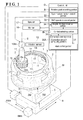
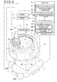
- a skiving device of the embodiment serving as a gear manufacturing device of the disclosure is disclosed in Figs. 1 to 3 .
- the skiving device provides a method for manufacturing a gear of the disclosure.
- the skiving device includes a table 2 rotatably supporting a ring-shaped work 1 about a work axis T, and a cutter (pinion cutter) 10 rotatably supported by a shaft holder 11 about a cutter axis S.
- the work axis T and the cutter axis S are positioned on skew axes (the work axis T and the cutter axis S are positioned on axes which are skew to each other).
- the table 2 is supported by a cutting operation mechanism M, and the table 2 includes a control unit D that controls the operation of the cutting operation mechanism M, the rotation of the work 1, and the rotation of the cutter 10.
- the table 2 includes plural chucks 3 that fix the work 1 which is an object for machining.
- the table 2 is rotatably supported about the work axis T relative to a shift frame 5, and is actuated to rotate by a table motor 2M.
- the cutter 10 is structured in a helical gear shape that includes plural blade portions 10A and is actuated to rotate by a cutter motor 10M. Further, a synchronous motor, for example, a stepping motor, is adopted for each of the table motor 2M and the cutter motor 10M.
- the cutting operation mechanism M includes the shift frame 5, a slide frame 6, a shift motor 5M, a first slide motor 6Ma, and a second slide motor 6Mb.
- the shift frame 5 is supported to be movable relative to the slide frame 6 along the work axis T.
- the slide frame 6 is supported by a frame of the skiving device so that the slide frame 6 is movable in two directions on an imaginary plane which is orthogonal to the work axis T.
- the shift motor 5M reciprocates the shift frame 5 in directions along the work axis T.
- the first slide motor 6Ma and the second slide motor 6Mb independently move the slide frame 6 to be reciprocated in directions being orthogonal to each other on the imaginary plane which is orthogonal to the work axis T.
- the work axis T and the cutter axis S are on axes which are skew to each other.
- the work axis T is positioned in parallel with a direction of a tooth trace of the gear formed, or to be formed on the work 1 (i.e., the direction in parallel with the work axis T).
- a direction of a tooth trace of a blade portion 10A of the cutter 10 is in parallel with the direction of the tooth trace of the gear formed, or to be formed on the work 1. Because of the arrangements described above, by the actuation of the shift motor 5M, the work 1 can be relatively moved in the direction of the work axis T relative to the blade portion 10A of the cutter 10.
- a relative position of the work 1 relative to the cutter 10 in a direction orthogonal to the work axis T can be determined desirably.
- a setting of a depth of the cutting by the blade portion 10A of the cutter 10 and the operation to separate the work 1 from the blade portion 10A of the cutter 10 can be performed.
- a shift operation by the shift motor 5M and a setting operation by the first slide motor 6Ma and the second slide motor 6Mb are performed by a feed screw
- the construction is not limited.
- the shift operation and the setting operation may be performed by a rack and pinion gears.
- the operation of the timing belt may be directly transmitted to perform the shift operation and the setting operation.
- the cutting operation mechanism M is not limited to the structure described above.
- the cutting operation mechanism M may include plural arms similar to a multiarticular robot arm.
- the cutter 10 may be supported by, for example, a multiarticular robot arm so that the cutter 10 is moved relative to the work 1 in a direction of the work axis T of the work 1 while rotating the table 2 at a fixed position in the skiving device.
- the skiving device may include a relative angle setting portion for determining the skew positions (attitude) of the work axis T and the cutter axis S.
- the relative angle setting portion may be either manually operated or driven by an electric motor.
- the control unit D sets, or determines a cutting depth by the cutter 10, synchronously drives the cutter motor 10M and the table motor 2M with a predetermined ratio of angular velocity at the position set, or determined by the control unit D, and controls the work 1 to shift, thus performing the cutting.
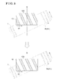
- the work 1 and the cutter 10 are synchronously rotated in the same speed at contact portions of the work 1 and the cutter 10.
- the velocity vector of the blade portion 10A of the cutter 10 i.e., the direction in S1 in Fig. 3
- the velocity vector of the work 1 i.e., the direction in R1 in Fig. 3
- "Sliding speed" is generated between the work 1 and the cutter 10 in a direction of the tooth trace by a difference of the velocity vectors.
- an entire region in a direction of the tooth trace of the work 1 is cut by moving the work 1 in a direction along the work axis T while cutting the work 1 using the "sliding speed.”
- an internal spur gear is formed on an inner circumference of the work 1.
- an internal helical gear may be formed on the inner circumference of the work 1.
- a vibration sensor 15 is disposed in the shaft holder 11 that rotatably supports a shaft of the cutter 10.
- the control unit D performs one of a position correction operation and a phase correction operation.
- the position correction operation is an operation for correcting a relative position of the cutter 10 relative to the work 1 in a direction for correcting the cutting depth in a case where an amplitude value of a vibration detected by the vibration sensor 15 reaches equal to or greater than a set value (predetermined value).
- the phase correction operation is an operation for correcting a relative phase of the cutter 10 and the work 1 in a direction for reducing an excessive cutting of one of a pair of tooth surfaces of the gear (in a direction to correct an unbalance cutting that is otherwise to be applied on a pair of tooth surfaces that structure a tooth portion formed on the work 1) in a case where an amplitude value of a vibration detected by the vibration sensor 15 reaches equal to or greater than a set value (predetermined value).
- the position correction operation is performed, whereas the phase correction operation is performed in a case where the amplitude of the vibration in a circumferential direction of the cutter 10 or the work 1 is detected to be equal to or greater than the set value.
- the direction for correcting the cutting depth basically corresponds to a direction for reducing the cutting depth.
- the vibration has a center of amplitude that does not allow the cutter 10 to cut the work 1 by a predetermined cutting depth and causes the reduction of the cutting depth
- the direction for correcting the cutting depth corresponds to a direction for increasing the cutting depth.
- a circular cutter is applied as the cutter 10, however, the configuration is not limited. For example, an elliptical (oval) cutter may be applied as the cutter 10.
- the vibration sensor 15 may be disposed in the shift frame 5 supporting the work 1. Alternatively, the vibration sensor 15 may be disposed in the shift frame 5 and the shaft holder 11. In a case where plural vibration sensors 15 are provided, according to an alternative construction, an average value of detection signals of the vibration sensors 15 may be applied, or weightings may be applied to plural detection signals.
- the control unit D includes a microprocessor and a digital signal processor (DSP), which is provided with software for performing the skiving (machining).
- the software includes a relative position setting portion 31, a synchronous rotation control portion 32, a shift operation control portion 33, an amplitude determination portion 34, a control selecting portion 35, a correction control portion 36, and an alert control portion 37.
- the control unit D is configured to output the information to a monitor 16 (e.g., liquid crystal screen) and a speaker 17.
- the control unit D includes an output interface that outputs control signals to drive circuits for the table motor 2M, the cutter motor 10M, the shift motor 5M, the first slide motor 6Ma, and the second slide motor 6Mb, and that outputs control signals to the monitor 16 and the speaker 17. Further, the control unit D includes an input interface for importing the detection signal of the vibration sensor 15 and detection signals of the sensors provided at each portion of the cutting operation mechanism M.
- the relative position setting portion 31, the synchronous rotation control portion 32, the shift operation control portion 33, the amplitude determination portion 34, the control selecting portion 35, the correction control portion 36, and the alert control portion 37 may be structured with hardware, for example, logic. Further alternatively, the relative position setting portion 31, the synchronous rotation control portion 32, the shift operation control portion 33, the amplitude determination portion 34, the control selecting portion 35, the correction control portion 36, and the alert control portion 37 may be structured with combinations of the hardware, for example, logic and the software.
- the relative position setting portion 31 sets, or determines relative position of the work 1 and the cutter 10 by moving the work 1 in a direction orthogonal to the work axis T by controlling one of or both of the first slide motor 6Ma and the second slide motor 6Mb. On the basis of the determined relative positions of the work 1 and the cutter 10, the cutting depth of the work 1 by the cutter 10 is corrected (position correction operation).
- the synchronous rotation control portion 32 synchronously drives the table motor 2M and the cutter motor 10M with the predetermined ratio of angular velocity so that contact portions of an inner circumference of the work 1 and an outer circumference of the cutter 10 rotate in the equal peripheral velocity.
- the synchronous rotation control portion 32 corrects the rotation phase of the work 1 and the cutter 10 (phase correction operation).
- the shift operation control portion 33 controls the shift motor 5M to move the work 1 integrally with the table 2 in a direction along the work axis T.
- the amplitude determination portion 34 includes a function of Fast Fourier Transform (FFT), and analyzes a vibration waveform detected by the vibration sensor 15 to determine the amplitude of the vibration associated with the cutting.
- FFT Fast Fourier Transform
- the control selecting portion 35 compares the amplitude value of the vibration determined at the amplitude determination portion 34 and predetermined thresholds (a limit value, a reference value, a set value). The control selecting portion 35 allows the control in response to results of the comparison.
- the correction control portion 36 performs a correction control for changing the relative position (relative positional relationship) of the work 1 and the cutter 10 on the basis of the amplitude value of the vibration determined in the amplitude determination portion 34. Further, the correction control portion 36 includes a correction amount computing portion 36A.
- the correction amount computing portion 36A calculates a correction amount for the position correction operation and the phase correction operation when it is determined that the amplitude value of the vibration detected by the vibration sensor 15 during the machining, or skiving reaches equal to or greater than the set value (predetermined value) by the amplitude determination portion 34.
- the position correction operation the correction amount for correcting the relative position (relative positional relationship) of the cutter 10 and the work 1 in a direction to reduce the cutting depth is calculated in response to the amplitude value.
- the correction amount for correcting the relative phase of the cutter 10 and the work 1 in a direction to reduce the excessive cutting is calculated in response to the amplitude value.
- the alert control portion 37 performs an abnormality alerting operation and a replacing alert operation on the basis of the amplitude value of the vibration generated during the machining, or skiving that the vibration sensor 15 detects. Then, the alert control portion 37 outputs the information in accordance with the operations to the monitor 16 and the speaker 17.
- Vibrations generated during the cutting will be explained as follows.
- the vibration may occur at a terminal end of the cut region, or a portion close to a terminal end of the cut region. It is considered that the vibration is caused by an unbalanced load applied to the blade portion of the cutter 10 when the end portion of the cutter 10 is disengaged from the work 1.
- the work axis T of the work 1 and the cutter axis S of the cutter 10 are arranged on the axes that are skew to each other.
- a preceding side downstream side of rotation
- a following side upstream side of rotation
- the leading side of the blade portion is disengaged (released) from the work first
- the trailing side is disengaged (released) from the work later at the completion of the cutting.
- the vibration is unlikely generated due to stable load applied to the cutter because the load is equally applied to the leading side and the trailing side of a cutting edge in a state where the cutting continues after starting the cutting.
- the vibration may be generated because the loads applied to the leading side and the trailing side are unbalanced at a timing when the leading side of the blade portion is disengaged (released) from the work at a terminal end of the cut region, or at a portion close to a terminal end of the cut region.
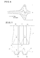
- Fig. 6 shows the vibration that occurs during the cutting. As illustrated in Fig. 6 , the amplitude of the vibration increases when the cutter 10 reaches a cutting end region (the region of the work 1 where the cutting by the cutter 10 ends; the terminal end of the cut region). In Fig. 6 , the maximum amplitude is indicated as a maximum amplitude value A.
- an addendum 1 T, a tooth surface 1 F, and a tooth space 1 B are formed on the work 1.
- the tooth surface 1 F is excessively cut and the width of the tooth space 1 B is increased.
- the tooth space 1 B is increased by a cutting error value P and/or a cutting error value P'.
- the cutting error value P usually has different value from the cutting error value P'.
- a control operation is executed so as to produce high quality gear by performing the correction operation for the control during the cutting process in response to the vibrations.
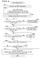
- control unit D sets the work 1 and the cutter 10 at an initial position, and starts a shift operation of the work 1 relative to the cutter 10 while synchronously rotating the work 1 and the cutter 10 (Step S101, Step S102).
- the relative position setting portion 31 controls the first slide motor 6Ma and the second slide motor 6Ma of the cutting operation mechanism M to integrally operate the slide frame 6 and the shift frame 5 so that the work 1 is set at the initial position relative to the cutter 10. Further, when the work 1 is set at the initial position relative to the cutter 10, the depth of the cutting by the cutter 10 is determined at a predetermined value.
- the synchronous rotation control portion 32 synchronously rotates the work 1 and the cutter 10.
- the shift operation control portion 33 operates the shift frame 5 to shift by the control of the shift motor 5M, and the cutting in the cutting process (machining) starts by operating the work 1 and the cutter 10 in a direction of the tooth trace of the work 1.
- the work 1 rotates in the primary rotation direction Rt and the cutter 10 rotates in the auxiliary rotation direction Rs.
- the "sliding, or sliding action (sliding speed)" is generated at the contact portions of the work 1 and the cutter 10 because the axes of the work 1 and the cutter 10 are skew.
- the cutting of the work 1 is performed in response to the shift operation of the cutter 10 in the direction of the tooth trace of the work 1 (i.e., in the direction of the work axis T) using the "sliding, or sliding action.”
- the detection signal of the vibration sensor 15 is obtained (Step S103).
- the amplitude determination portion 34 determines the amplitude value based on the detected vibration. Then, the amplitude value, the limitation value, the reference value, and the set value are compared. Based on the comparison results, in a case where the amplitude value is equal to or greater than the limitation value, it is informed, or alerted that the cutting cannot be operated (Step S104, Step S105). Further, in a case where the amplitude value is equal to or greater than the reference value, it is informed, or alerted that the cutter 10 needs to be replaced with the new (Step S106, Step S107). Further, in a case where the amplitude value is equal to or greater than the set value, the correction operation is performed (Step S108, Step S200).
- the maximum amplitude value detected by the vibration sensor 15 when the cutting by the cutter 10 cannot be performed is set as the limitation value.
- the alert control portion 37 displays a message indicating that the operation stops due to the generation of the abnormality on the monitor 16 as the abnormality alerting operation, and the alert control portion 37 outputs sounds, or an aural message (verbal message may also be applicable) that makes an operator notice the generation of the abnormality to the speaker 17.
- the cutting cannot be performed (cutting is not operable), for example, because of the abnormal state of the cutter 10.
- the work 1 and the cutter 10 are disengaged, and then the rotation of the work 1 and the cutter 10 is stopped (a control for stopping the rotation of the work 1 and the cutter 10 is performed after separating the work 1 and the cutter 10)(Step S111).
- an amplitude value that is greater than an amplitude of the vibration caused when the cutting is performed in a favorable state of the blade portion 10A of the cutter 10 is set as the set value.
- the set value is predetermined to be smaller than the reference value.
- the alert control portion 37 operates a replacing period alerting operation to display a message that the cutting capacity of the cutter 10 is declined and the cutter 10 needs to be replaced with the new on the monitor 16, and outputs the sounds, or aural message (verbal message may also be applicable) that urges an operator to replace the cutter 10 to the speaker 17.
- the transaction proceeds to a correction control executed by the correction control portion 36 (Step S200).
- the correction control is set as a sub-routine, which will be described hereinafter.
- Step S109, Step S110, Step S111 a relative positional relationship of the work 1 and the cutter 10 in a shift direction is obtained, transactions of Step 103 to Step 109 are repeated until the cutting is completed from the relative position, and the cutting operation is ended when the cutting is completed.
- Step S105 the skiving device is not capable of cutting (cutting is not operable) in Step S105 and the alerting in association with that the cutting cannot be performed is outputted, or in a case where it is determined that the cutter 10 needs to be replaced and the alerting in association with replacing the cutter 10 is outputted, a control for continuously informing the alerted contents is executed.
- the correction operation will be explained in detail hereinafter.
- the maximum amplitude value A and the cutting error values P, P' are set as the arithmetic operation data, and an amplitude value X determined by the amplitude determination portion 34 based on the detection signal from the vibration sensor 15 is set, the correction control portion 36 calculates a correction amount f(x), and the correction (position correction, position correction operation) is executed (Step S201, Step S202, Step S203).
- the maximum amplitude value A and the cutting error values P, P' which are the same values explained above, are stored in, for example, a nonvolatile memory in the control unit D.
- the maximum amplitude value A is measured by the vibration sensor 15 during an experimental (pilot) cutting.
- the cutting error values P, P' are obtained by measuring an error of the tooth space 1 B of the work 1 machined (skived) in the experimental (pilot) cutting process.
- the amplitude value X is determined by the amplitude determination portion 34 based on the detection signal of the vibration sensor 15.
- the correction amount f(x) is calculated on the basis of an arithmetic expression (operation expression) shown in Step S202 in Fig. 5 .
- the average value of the cutting error values P, P' is obtained, and an amplitude ratio is obtained from the amplitude value X and the maximum amplitude value A.
- the average value of the cutting error values P, P' is multiplied by the amplitude ratio and a constant C.
- the constant C is set for obtaining an appropriate correction amount.
- the correction amount is calculated by a feedback control based on the amplitude value X
- the correction amount f(x) changes in response to changes in the amplitude value X.
- the work 1 is moved in a direction to separate the work 1 from the cutter 10 in order to displace the work 1 to reduce the cutting depth by the cutter 10.
- a correction amount g(x) is calculated on the basis of the set arithmetic operation data and the amplitude value X determined by the amplitude determination portion 34 from the vibration sensor 15 to execute the correction (Step S204, S205, S206).
- the control is performed with a premise that there is a difference between the cutting error value P and the cutting error value P', and the relative phase of the cutter 10 and the work 1 is corrected in a direction to reduce the excessive cutting (correction operation, phase correction operation).
- the vibration sensor 15 may be configured to detect the vibration in a tangential direction at contact portions of the work 1 and the cutter 10, and whether the correction is necessary may be determined on the basis of determination results by determining whether the amplitude in a direction that the phase advances is greater or whether the amplitude in a direction that the phase delays is greater on the basis of the detected result by the vibration sensor 15.
- the correction amount g(x) is calculated on the basis of an arithmetic expression (operation expression) shown in Step S205 in Fig. 5 .
- the value obtained by dividing the absolute value of the difference of the cutting error values P, P' by a correction coefficient is multiplied by 2 ⁇ and is further multiplied by the amplitude ratio obtained from the amplitude value X and the maximum amplitude value A.
- the correction amount g(x) calculated as described above corresponds to a correction amount in a circumferential direction of the work 1 (phase angle), and a phase correction which changes a phase in the predetermined direction among the direction to advance the phase and the direction to delay the phase is performed.
- the rotational phase of the work 1 is regulated, or adjusted in a state where the angular velocity of the cutter 10 is maintained.
- the rotational phase of the cutter 10 may be regulated, or adjusted in a state where the rotation speed of the work 1 is maintained.
- the position correction operation is performed and the phase correction is performed as necessity arises, however, the construction of the control is not limited. Alternatively, the position correction operation only may be performed, or the phase correction operation only may be performed. Further, alternatively, the phase correction control is performed and the position correction control may be performed as necessity arises.
- the correction operation in which the relative positional relationship of the cutter 10 and the work 1 is corrected in a direction to correct the cutting depth (basically, in a direction to reduce, or to shallow the cutting depth) by the feedback control corresponding to the amplitude value. Accordingly, the amplitude of the vibration is restrained, and the drawback that the tooth surface 1 F of the gear formed on the work 1 is excessively cut is solved, and the width of the tooth space 1 B is set at a necessary value, thus the gear is finished to have high quality.
- the amplitude of the vibration during the cutting reaches equal to or greater than the set value and the only one of the tooth surfaces of the gear 1 F serving as a pair is to be excessively cut, by correcting the relative phase during the cutting, the cutting is performed without biasing, or the balanced cutting is performed, and thus the gear with high quality can be obtained.
- the tooth space 1 B of the gear is assumed to be shallower, or reduced, however, because bottomland portion does not work for, or is not involved with the gear engagement, capacity or performance of the gear does not decline.
- the amplitude of the vibration detected by the vibration sensor 15 reaches equal to or greater than the limitation value (e.g., a case where the blade portion 10A of the cutter 10 is damaged)
- the message urging to stop the operation because of the occurrence of the abnormality is displayed on the monitor 16 as the abnormality alerting operation and the aural message informing the occurrence of the abnormality is outputted to the speaker 17.
- the work 1 is disengaged, or separated from the cutter 10 and the rotation of the cutter 10 and the work 1 is stopped.
- the generation of the abnormality is securely recognized by an operator and wasteful machining can be avoided.
- the message indicating that the cutting capacity of the cutter 10 is declined and the cutter 10 needs to be replaced is displayed on the monitor 16 and outputs an aural message urging to replace the cutter 10 to the speaker 17 as the replacing period alerting operation.
- a construction of a gear manufacturing device or a skiving device may be modified as follows.
- the correction control portion 36 may include a correction amount reference table 36B and a correction amount read out portion 36C.
- the correction amount read out portion 36C reads out the correction amount from the correction amount reference table 36B on the basis of the amplitude value from the vibration sensor 15 to perform the correction operation.
- the maximum amplitude value A and the cutting error values P, P' are obtained, and plural amplitude ratios are obtained by operation (arithmetic operation) similar to the operation shown in Step S202 in Fig. 5 on the basis of the maximum amplitude value A and plural predicted amplitude values that the vibration sensor 15 possibly detects during the cutting process.
- the correction amount of the phase correction operation and the correction amount of the position correction operation relative to the amplitude value X detected by the vibration sensor 15 (similar to the correction amount f(x) in Step S202 in Fig. 5 ) are obtained by an arithmetic operation, are tabulated, and are stored in the correction amount reference table 36B constructed with, for example, a nonvolatile memory.
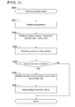
- Step S200 a control in accordance with a flowchart shown in Fig. 9 is performed.
- the amplitude value X determined by the amplitude determination portion 34 based on the detection signal from the vibration sensor 15 is set, the correction amount read out portion 36C reads out the correction amount of the position correction operation from the correction amount reference table 36B, and the position correction operation is performed on the basis of the correction amount (Step S201, Step S202, Step S203).
- the correction amount read out portion 36C reads out the correction amount of the phase correction operation from the correction amount reference table 36B based on the amplitude value X, and the phase correction operation is performed on the basis of the correction amount (Step S204, Step S205, Step S206).
- the control according to the first modified example is included within a range of the feedback control, however, because there is no need to execute the arithmetic operation, swift operation can be performed and a gear with high quality can be attained by an operation with high precision without causing a delay of the control.
- the position correction operation is executed and the phase correction is executed as necessary arises, however, the construction is not limited.
- the position correction operation only may be executed.
- the phase correction operation only may be executed.
- the phase correction control may be executed, and the position correction control may be executed as necessity arises.
- FIG. 10 A second modified example is shown in Fig. 10 .
- the correction operation is operated on the basis of a relative positional relationship between the work 1 and the cutter 10 in the cutting process according to the second modified example.
- the vibration sensor 15 is not provided, and the correction control portion 36 includes a correction amount setting table 36D and a correction amount obtaining portion 36E.
- the correction amount obtaining portion 36E reads out the correction amount from the correction amount setting table 36D in association with (in coordination with) the shift operation to performed the correction operation.
- the correction amount to the shift amount is tabulated, and the correction amount of the position correction operation and the correction amount of the phase correction operation are stored in the correction amount setting table 36D that is constructed with a nonvolatile memory.
- the cutting position of the cutter 10 relative to the work 1 is obtained from the shift amount of the work 1
- the correction amount obtaining portion 36E reads out the correction amount of the position correction operation from the correction amount setting table 36D on the basis of the cutting position, and the position correction operation is performed on the basis of the correction amount of the position correction operation (Step S201, Step S202, Step S203).
- the cutting position of the cutter 10 relative to the work 1 is obtained from the shift amount of the work 1
- the correction amount obtaining portion 36E reads out the correction amount of the phase correction operation from the correction amount setting table 36D on the basis of the cutting position, and the phase correction operation is performed on the basis of the correction amount of the phase correction operation (Step S204, Step S205, Step S206).
- the correction amount of the position correction operation and the correction amount of the phase correction operation of the second modified example are pre-obtained values by the arithmetic operation using the vibration sensor 15 described in the embodiment. In place of the amplitude value, the correction amount is read out on the basis of the shift amount according to the second modified example.
- the position correction operation is performed and the phase correction is executed as necessity arises, however, the construction is not limited.
- the position correction operation only may be executed.
- the phase correction operation only may be executed.
- the phase correction control may be executed and the position correction control may be executed as necessity arises.
- a structure which includes a laser light source and a photodetector may be applied as the vibration sensor.
- the photodetector receives a reflected light from an object to which the laser is irradiated, and the vibration is detected by the photodetector.
- an acceleration sensor may be applied as the vibration sensor.
- the vibration sensor 15 may be provided at a member that supports the work 1.
- a gear manufacturing device includes a control unit (D) for synchronously rotating a work (1) rotatably supported about a work axis (T) and a cutter (10) formed in a gear shape and rotatably supported about a cutter axis (S), the work axis (T) and the cutter axis (S) being skew to each other, the control unit (D) relatively moving the cutter (10) and the work (1) in an axial direction of the work (1) with a predetermined cutting depth.
- a control unit (D) for synchronously rotating a work (1) rotatably supported about a work axis (T) and a cutter (10) formed in a gear shape and rotatably supported about a cutter axis (S), the work axis (T) and the cutter axis (S) being skew to each other, the control unit (D) relatively moving the cutter (10) and the work (1) in an axial direction of the work (1) with a predetermined cutting depth.
- the gear manufacturing device further includes a correction control portion (36) executing at least one of a position correction and a phase correction when the cutter (10) reaches a predetermined terminal end region in a cut region, the position correction for correcting a relative positional relationship of the cutter (10) and the work (1) in a direction to correct the cutting depth, the phase correction for correcting a phase of the cutter (10) and the work (1) in a direction to correct unbalance cutting of a pair of tooth surfaces that structure a tooth portion formed on the work (1).
- a correction control portion (36) executing at least one of a position correction and a phase correction when the cutter (10) reaches a predetermined terminal end region in a cut region, the position correction for correcting a relative positional relationship of the cutter (10) and the work (1) in a direction to correct the cutting depth, the phase correction for correcting a phase of the cutter (10) and the work (1) in a direction to correct unbalance cutting of a pair of tooth surfaces that structure a tooth portion formed on the work (1).
- the correction control portion (36) executes at least one of the correction for correcting the relative positional relationship of the cutter (10) and the work (1) in a direction to reduce the cutting depth and the correction for correcting the phase of the cutter (10) and the work (1) in a direction to correct the unbalance cutting that is otherwise to be applied on the tooth surfaces of the tooth portion serving as a pair, the tooth surfaces formed on the work (1).
- the vibration is likely generated at the terminal end region of the cutting and the terminal end region can be identified in advance (pre-estimated).
- the load applied to the cutter (10) is reduced by the correction, thus the vibration can be restrained from occurring and the excessive cutting can be restrained.
- the machining precision is enhanced by restraining the vibration when manufacturing the gear by skiving and the gear manufacturing device for manufacturing a gear with high precision can be attained without using the vibration sensor (even if the vibration sensor is not applied).
- the gear manufacturing device includes the correction control portion (36) which includes a correction amount setting table (36D) in which a correction amount related to a relative position of the cutter (10) and the work (1) at the terminal end region is stored.
- the correction control portion (36) which includes a correction amount setting table (36D) in which a correction amount related to a relative position of the cutter (10) and the work (1) at the terminal end region is stored.
- the amplitude value of the vibration is different in accordance with the relative position of the work (1) and the cutter (10), and thus the correction amount related to the amplitude value is different in accordance with the relative position of the work (1) and the cutter (10).
- the correction amount setting table (36D) by storing the correction amount to the relative position of the work (1) and the cutter (10) being positioned at the terminal end region in the correction amount setting table (36D), the correction can be performed with an appropriate correction amount setting when performing the cutting at the terminal end region.
- a gear manufacturing device includes a control unit (D) for synchronously rotating a work (1) rotating about a work axis (T) and a cutter (10) rotating about a cutter axis (S), the work axis (T) and the cutter axis (S) being skew to each other, the control unit (D) relatively moving the cutter (10) and the work (1) in an axial direction of the work (1) with a predetermined cutting depth, and a correction control portion (36) executing at least one of a position correction and a phase correction when an amplitude value of a vibration detected by a vibration sensor (15) during a machining reaches equal to or greater than a set value, the position correction for correcting a relative positional relationship in a direction to correct the cutting depth, the phase correction for correcting a relative phase in a direction to correct an unbalance cutting that is otherwise to be applied on a pair of tooth surfaces formed on the work (1).
- a control unit (D) for synchronously rotating a work (1) rotating about a work axis (
Landscapes
- Engineering & Computer Science (AREA)
- Mechanical Engineering (AREA)
- Human Computer Interaction (AREA)
- Manufacturing & Machinery (AREA)
- Physics & Mathematics (AREA)
- General Physics & Mathematics (AREA)
- Automation & Control Theory (AREA)
- Gear Processing (AREA)
- Numerical Control (AREA)
- Machine Tool Sensing Apparatuses (AREA)
Applications Claiming Priority (1)
| Application Number | Priority Date | Filing Date | Title |
|---|---|---|---|
| JP2013197181A JP6201565B2 (ja) | 2013-09-24 | 2013-09-24 | 歯車製造方法 |
Publications (2)
| Publication Number | Publication Date |
|---|---|
| EP2853331A2 true EP2853331A2 (de) | 2015-04-01 |
| EP2853331A3 EP2853331A3 (de) | 2016-04-06 |
Family
ID=51609952
Family Applications (1)
| Application Number | Title | Priority Date | Filing Date |
|---|---|---|---|
| EP14185886.0A Withdrawn EP2853331A3 (de) | 2013-09-24 | 2014-09-23 | Vorrichtung und Verfahren zum Herstellen eines Zahnrads |
Country Status (3)
| Country | Link |
|---|---|
| US (1) | US20150088298A1 (de) |
| EP (1) | EP2853331A3 (de) |
| JP (1) | JP6201565B2 (de) |
Cited By (4)
| Publication number | Priority date | Publication date | Assignee | Title |
|---|---|---|---|---|
| WO2017076503A1 (de) * | 2015-11-05 | 2017-05-11 | Gleason-Pfauter Maschinenfabrik Gmbh | Verfahren zum erzeugen oder bearbeiten von verzahnungen an werkstücken |
| CN107433492A (zh) * | 2017-07-31 | 2017-12-05 | 成都飞机工业(集团)有限责任公司 | 一种铣削颤振测试件及其测试方法 |
| DE102016212287A1 (de) * | 2016-07-06 | 2018-01-11 | Zf Friedrichshafen Ag | Verfahren zur Bearbeitung eines Werkstücks auf einer Werkzeugmaschine |
| WO2020212123A1 (de) * | 2019-04-15 | 2020-10-22 | Gleason-Pfauter Maschinenfabrik Gmbh | Verfahren des erzeugens oder bearbeitens einer verzahnung |
Families Citing this family (14)
| Publication number | Priority date | Publication date | Assignee | Title |
|---|---|---|---|---|
| DE102012022439A1 (de) * | 2012-11-16 | 2014-05-22 | Marcel Sobczyk | Verfahren zur Bestimmung der Freiflächenkontur eines Wälzschälwerkzeuges, Wälzschälwerkzeug und dessen Verwendung |
| JP6427897B2 (ja) * | 2014-03-03 | 2018-11-28 | 株式会社ジェイテクト | 歯車加工装置 |
| JP2016215327A (ja) * | 2015-05-21 | 2016-12-22 | 株式会社カシフジ | スカイビング加工装置 |
| JP6720543B2 (ja) * | 2016-01-14 | 2020-07-08 | アイシン精機株式会社 | 歯車加工方法 |
| WO2018070403A1 (ja) * | 2016-10-13 | 2018-04-19 | 株式会社ジェイテクト | 歯車加工装置及び歯車加工方法 |
| JP7024303B2 (ja) * | 2016-10-13 | 2022-02-24 | 株式会社ジェイテクト | 歯車加工装置及び歯車加工方法 |
| DE102017010598A1 (de) * | 2017-11-15 | 2019-05-16 | Gleason-Pfauter Maschinenfabrik Gmbh | Verfahren zur Bearbeitung einer Verzahnung und Verzahnungsmaschine |
| JP7167631B2 (ja) * | 2018-10-30 | 2022-11-09 | 株式会社ジェイテクト | 工作機械及び工作機械を用いた歯車加工方法 |
| JP7225715B2 (ja) * | 2018-11-12 | 2023-02-21 | 株式会社ジェイテクト | 歯車加工方法及び歯車加工装置 |
| JP7347028B2 (ja) * | 2019-08-30 | 2023-09-20 | 株式会社ジェイテクト | 歯車加工装置及び歯車加工方法 |
| WO2021260921A1 (ja) * | 2020-06-26 | 2021-12-30 | 三菱電機株式会社 | バックラッシ量測定装置、学習済みの学習モデル生成装置、学習用データ生成装置、バックラッシ量測定方法、学習済みの学習モデル生成方法、学習用データ生成方法、バックラッシ量測定プログラム、学習済みの学習モデル生成プログラム、及び学習用データ生成プログラム |
| EP3932600B1 (de) * | 2020-06-30 | 2024-02-14 | 3M Innovative Properties Company | Verfahren zum schleifen und polieren von zahnrädern |
| CN114682857B (zh) * | 2022-03-15 | 2023-10-27 | 西北工业大学 | 一种面齿轮车齿加工齿面误差的矫正方法 |
| CN115452127B (zh) * | 2022-11-11 | 2023-03-03 | 日照市计量科学研究院 | 一种滚齿机主轴振动激光测试装置 |
Citations (1)
| Publication number | Priority date | Publication date | Assignee | Title |
|---|---|---|---|---|
| JP2012045687A (ja) | 2010-08-30 | 2012-03-08 | Aisin Seiki Co Ltd | 歯車製造方法 |
Family Cites Families (15)
| Publication number | Priority date | Publication date | Assignee | Title |
|---|---|---|---|---|
| FR2299935A1 (fr) * | 1975-02-07 | 1976-09-03 | Renault Ind Equip Tech | Nouveau procede de rasage et de roulage differentiel de dentures et machine en faisant applicatio |
| JPS5818183B2 (ja) * | 1978-05-30 | 1983-04-12 | 株式会社小松製作所 | フライスカツタのチツプ破損検出装置 |
| GB8300792D0 (en) * | 1983-01-12 | 1983-02-16 | Production Eng Res | Monitoring tool life |
| DD256545A1 (de) * | 1987-01-23 | 1988-05-11 | Polygraph Leipzig | Verfahren und vorrichtung zum ausgleich von drehwinkelfehlern in zahnradgetrieben |
| EP0311778B1 (de) * | 1987-10-13 | 1992-10-28 | HURTH MASCHINEN UND WERKZEUGE G.m.b.H. | Verfahren zum Feinbearbeiten von balligen Zahnflanken an insbesondere gehärteten Zahnrädern |
| JP2969643B2 (ja) * | 1989-03-17 | 1999-11-02 | 松下電器産業株式会社 | 歯車加工装置 |
| JPH0432822U (de) * | 1990-07-16 | 1992-03-17 | ||
| JP2009190096A (ja) * | 2008-02-12 | 2009-08-27 | Mazda Motor Corp | 歯車の加工方法及び加工装置 |
| DE102008037514B4 (de) * | 2008-11-03 | 2024-06-20 | Profilator Gmbh & Co. Kg | Wälzschälvorrichtung und -verfahren |
| JP2010257010A (ja) * | 2009-04-22 | 2010-11-11 | Mitsubishi Heavy Ind Ltd | 工作機械制御装置 |
| WO2011043225A1 (ja) * | 2009-10-05 | 2011-04-14 | 本田技研工業株式会社 | 歯面振れ測定装置及び歯面振れ測定方法、研削工具成形装置及び研削工具成形方法、並びに、歯車研削装置の歯合わせ方法 |
| TWI400591B (zh) * | 2010-03-12 | 2013-07-01 | Ind Tech Res Inst | 具有線上振動偵測調控之工具機 |
| JP5473790B2 (ja) * | 2010-06-07 | 2014-04-16 | 三菱重工業株式会社 | ギヤシェーパ、及びギヤシェーパの制御方法 |
| JP5536608B2 (ja) * | 2010-10-13 | 2014-07-02 | オークマ株式会社 | 工作機械における振動抑制方法及び振動抑制装置 |
| JP2012171020A (ja) * | 2011-02-17 | 2012-09-10 | Aisin Seiki Co Ltd | 歯車製造方法 |
-
2013
- 2013-09-24 JP JP2013197181A patent/JP6201565B2/ja not_active Expired - Fee Related
-
2014
- 2014-09-23 US US14/493,852 patent/US20150088298A1/en not_active Abandoned
- 2014-09-23 EP EP14185886.0A patent/EP2853331A3/de not_active Withdrawn
Patent Citations (1)
| Publication number | Priority date | Publication date | Assignee | Title |
|---|---|---|---|---|
| JP2012045687A (ja) | 2010-08-30 | 2012-03-08 | Aisin Seiki Co Ltd | 歯車製造方法 |
Non-Patent Citations (1)
| Title |
|---|
| KOJIMA MASAKAZU; NISHIJIMA KOMIO: "Transactions of the Japan Society of Mechanical Engineers", vol. 39, article "Study in Skiving of Internal Spur Gear: Part 1, On Cutter Profile", pages: 2580 - 2586 |
Cited By (7)
| Publication number | Priority date | Publication date | Assignee | Title |
|---|---|---|---|---|
| WO2017076503A1 (de) * | 2015-11-05 | 2017-05-11 | Gleason-Pfauter Maschinenfabrik Gmbh | Verfahren zum erzeugen oder bearbeiten von verzahnungen an werkstücken |
| US10747191B2 (en) | 2015-11-05 | 2020-08-18 | Gleason-Pfauter Maschinenfabrik Gmbh | Method for creating or machining toothings on workpieces by gear shaping with regulation of spindle rotation setpoints |
| DE102016212287A1 (de) * | 2016-07-06 | 2018-01-11 | Zf Friedrichshafen Ag | Verfahren zur Bearbeitung eines Werkstücks auf einer Werkzeugmaschine |
| CN107433492A (zh) * | 2017-07-31 | 2017-12-05 | 成都飞机工业(集团)有限责任公司 | 一种铣削颤振测试件及其测试方法 |
| CN107433492B (zh) * | 2017-07-31 | 2019-03-05 | 成都飞机工业(集团)有限责任公司 | 一种铣削颤振测试件及其测试方法 |
| WO2020212123A1 (de) * | 2019-04-15 | 2020-10-22 | Gleason-Pfauter Maschinenfabrik Gmbh | Verfahren des erzeugens oder bearbeitens einer verzahnung |
| US12472569B2 (en) | 2019-04-15 | 2025-11-18 | Gleason-Pfauter Maschinenfabrik Gmbh | Method for producing or machining toothing |
Also Published As
| Publication number | Publication date |
|---|---|
| JP6201565B2 (ja) | 2017-09-27 |
| US20150088298A1 (en) | 2015-03-26 |
| EP2853331A3 (de) | 2016-04-06 |
| JP2015062967A (ja) | 2015-04-09 |
Similar Documents
| Publication | Publication Date | Title |
|---|---|---|
| EP2853331A2 (de) | Vorrichtung und Verfahren zum Herstellen eines Zahnrads | |
| JP6625794B2 (ja) | びびり振動を抑制可能な主軸安定回転数の算出方法、その報知方法、主軸回転数制御方法及びncプログラム編集方法、並びにその装置。 | |
| JP5258921B2 (ja) | 工作機械及びその加工制御装置 | |
| JP5908342B2 (ja) | 工作機械の加工振動抑制方法及び加工振動抑制装置 | |
| US10545477B2 (en) | Numerical controller having cutting in/out motion inserting function or circular motion inserting function | |
| WO2014115395A1 (ja) | 切削振動抑止方法、演算制御装置、および工作機械 | |
| US9869989B2 (en) | Numerical controller | |
| JP2012213830A5 (de) | ||
| JP6700061B2 (ja) | 旋削加工方法及びそれを用いた工作機械 | |
| JP2010105160A (ja) | 機械加工装置、機械加工装置の回転数演算装置、機械加工装置のびびり振動評価装置および機械加工装置のびびり振動評価方法 | |
| EP2500132A1 (de) | Verfahren und steuervorrichtung für ein maschinenwerkzeug | |
| JP4620148B2 (ja) | サーボモータ制御装置 | |
| JP6302794B2 (ja) | 回転速度表示方法 | |
| JP6695306B2 (ja) | 工作機械、加工方法、および加工プログラム | |
| JP2012093983A (ja) | 振動表示装置 | |
| JP2019069490A (ja) | 工作機械、加工方法、および加工プログラム | |
| US10409259B2 (en) | Servomotor control device | |
| JP6415783B1 (ja) | レーザ加工機およびレーザ加工システム | |
| US20210080923A1 (en) | Diagnostic apparatus and diagnostic method | |
| JP7436174B2 (ja) | 工作機械 | |
| JP7168421B2 (ja) | プログラム作成支援装置およびプログラム作成支援方法 | |
| CN110303346B (zh) | 电动机控制装置 | |
| CN110315388B (zh) | 电动机控制装置 | |
| JP5736946B2 (ja) | 切断装置の刃間隙間の調整装置およびこれを用いる刃間隙間の調整方法 | |
| CN115629627B (zh) | 负载端转矩波动抑制方法、电子设备及存储介质 |
Legal Events
| Date | Code | Title | Description |
|---|---|---|---|
| PUAI | Public reference made under article 153(3) epc to a published international application that has entered the european phase |
Free format text: ORIGINAL CODE: 0009012 |
|
| 17P | Request for examination filed |
Effective date: 20140923 |
|
| AK | Designated contracting states |
Kind code of ref document: A2 Designated state(s): AL AT BE BG CH CY CZ DE DK EE ES FI FR GB GR HR HU IE IS IT LI LT LU LV MC MK MT NL NO PL PT RO RS SE SI SK SM TR |
|
| AX | Request for extension of the european patent |
Extension state: BA ME |
|
| PUAL | Search report despatched |
Free format text: ORIGINAL CODE: 0009013 |
|
| AK | Designated contracting states |
Kind code of ref document: A3 Designated state(s): AL AT BE BG CH CY CZ DE DK EE ES FI FR GB GR HR HU IE IS IT LI LT LU LV MC MK MT NL NO PL PT RO RS SE SI SK SM TR |
|
| AX | Request for extension of the european patent |
Extension state: BA ME |
|
| RIC1 | Information provided on ipc code assigned before grant |
Ipc: B23F 23/10 20060101ALI20160301BHEP Ipc: B23F 5/16 20060101ALI20160301BHEP Ipc: B23F 23/00 20060101AFI20160301BHEP Ipc: G05B 19/18 20060101ALI20160301BHEP Ipc: B23Q 17/12 20060101ALI20160301BHEP Ipc: B23F 23/12 20060101ALI20160301BHEP |
|
| R17P | Request for examination filed (corrected) |
Effective date: 20161005 |
|
| RBV | Designated contracting states (corrected) |
Designated state(s): AL AT BE BG CH CY CZ DE DK EE ES FI FR GB GR HR HU IE IS IT LI LT LU LV MC MK MT NL NO PL PT RO RS SE SI SK SM TR |
|
| STAA | Information on the status of an ep patent application or granted ep patent |
Free format text: STATUS: THE APPLICATION HAS BEEN WITHDRAWN |
|
| 18W | Application withdrawn |
Effective date: 20171027 |