EP2853219B1 - Instrument permettant de sceller un vaisseau - Google Patents
Instrument permettant de sceller un vaisseau Download PDFInfo
- Publication number
- EP2853219B1 EP2853219B1 EP13184185.0A EP13184185A EP2853219B1 EP 2853219 B1 EP2853219 B1 EP 2853219B1 EP 13184185 A EP13184185 A EP 13184185A EP 2853219 B1 EP2853219 B1 EP 2853219B1
- Authority
- EP
- European Patent Office
- Prior art keywords
- instrument according
- tissue contact
- plastic body
- tissue
- openings
- Prior art date
- Legal status (The legal status is an assumption and is not a legal conclusion. Google has not performed a legal analysis and makes no representation as to the accuracy of the status listed.)
- Revoked
Links
Images


Classifications
-
- A—HUMAN NECESSITIES
- A61—MEDICAL OR VETERINARY SCIENCE; HYGIENE
- A61B—DIAGNOSIS; SURGERY; IDENTIFICATION
- A61B18/00—Surgical instruments, devices or methods for transferring non-mechanical forms of energy to or from the body
- A61B18/04—Surgical instruments, devices or methods for transferring non-mechanical forms of energy to or from the body by heating
- A61B18/12—Surgical instruments, devices or methods for transferring non-mechanical forms of energy to or from the body by heating by passing a current through the tissue to be heated, e.g. high-frequency current
- A61B18/14—Probes or electrodes therefor
- A61B18/1442—Probes having pivoting end effectors, e.g. forceps
- A61B18/1445—Probes having pivoting end effectors, e.g. forceps at the distal end of a shaft, e.g. forceps or scissors at the end of a rigid rod
-
- A—HUMAN NECESSITIES
- A61—MEDICAL OR VETERINARY SCIENCE; HYGIENE
- A61B—DIAGNOSIS; SURGERY; IDENTIFICATION
- A61B18/00—Surgical instruments, devices or methods for transferring non-mechanical forms of energy to or from the body
- A61B18/04—Surgical instruments, devices or methods for transferring non-mechanical forms of energy to or from the body by heating
- A61B18/12—Surgical instruments, devices or methods for transferring non-mechanical forms of energy to or from the body by heating by passing a current through the tissue to be heated, e.g. high-frequency current
- A61B18/14—Probes or electrodes therefor
-
- A—HUMAN NECESSITIES
- A61—MEDICAL OR VETERINARY SCIENCE; HYGIENE
- A61B—DIAGNOSIS; SURGERY; IDENTIFICATION
- A61B18/00—Surgical instruments, devices or methods for transferring non-mechanical forms of energy to or from the body
- A61B2018/00571—Surgical instruments, devices or methods for transferring non-mechanical forms of energy to or from the body for achieving a particular surgical effect
- A61B2018/0063—Sealing
-
- A—HUMAN NECESSITIES
- A61—MEDICAL OR VETERINARY SCIENCE; HYGIENE
- A61B—DIAGNOSIS; SURGERY; IDENTIFICATION
- A61B18/00—Surgical instruments, devices or methods for transferring non-mechanical forms of energy to or from the body
- A61B18/04—Surgical instruments, devices or methods for transferring non-mechanical forms of energy to or from the body by heating
- A61B18/12—Surgical instruments, devices or methods for transferring non-mechanical forms of energy to or from the body by heating by passing a current through the tissue to be heated, e.g. high-frequency current
- A61B18/14—Probes or electrodes therefor
- A61B18/1442—Probes having pivoting end effectors, e.g. forceps
- A61B2018/1452—Probes having pivoting end effectors, e.g. forceps including means for cutting
- A61B2018/1455—Probes having pivoting end effectors, e.g. forceps including means for cutting having a moving blade for cutting tissue grasped by the jaws
-
- Y—GENERAL TAGGING OF NEW TECHNOLOGICAL DEVELOPMENTS; GENERAL TAGGING OF CROSS-SECTIONAL TECHNOLOGIES SPANNING OVER SEVERAL SECTIONS OF THE IPC; TECHNICAL SUBJECTS COVERED BY FORMER USPC CROSS-REFERENCE ART COLLECTIONS [XRACs] AND DIGESTS
- Y10—TECHNICAL SUBJECTS COVERED BY FORMER USPC
- Y10T—TECHNICAL SUBJECTS COVERED BY FORMER US CLASSIFICATION
- Y10T29/00—Metal working
- Y10T29/49—Method of mechanical manufacture
- Y10T29/49002—Electrical device making
- Y10T29/49117—Conductor or circuit manufacturing
Definitions
- the invention relates to a surgical instrument for tissue coagulation, in particular for vessel sealing.
- tissue coagulation in particular for vessel sealing.
- Such instruments can be used, for example, for sealing, welding and coagulating tissue, for example blood vessels. It may be provided to sever the tissue after coagulation as well.
- distal always describes the part of the instrument or component removed by the user
- proximal always describes the closer part of the instrument or component directed towards the user
- Instruments of the type mentioned are basically known.
- the EP 2371316 A1 such an instrument having an elongated shaft held at its proximal end to a housing from which it extends.
- a handle and an actuating lever are formed on the housing.
- a pincer-like tool with two branches is arranged, which are also referred to as jaw parts. While one of the jaws is fixed, the other is movable toward and away from the fixed jaw part. To move it is connected via traction means and a transmission with the operating lever.
- the jaw parts can be energized during use in order to heat a captured between the jaws biological tissue, such as a blood vessel, by means of current flow.
- the tool may include a knife around a fused and fused between the branches To cut through the vessel.
- Such instruments are used both as sterilizable instruments and as disposable instruments.
- disposable instruments a simple and inexpensive construction is important, but no compromises in terms of functionality are desired.
- reusable instruments easy cleanability and sterilizability and robustness against high temperatures or other sterilization effects are important. Again, compromises in terms of functionality are not desirable or acceptable.
- the instrument according to the invention comprises a tool with at least one movable branch which comprises a sector support and an electrode unit.
- the electrode unit consists of a sheet metal part preferably made as a stamped and bent part, which is partially embedded in a plastic body and anchored in this.
- the sheet metal part at two long, opposite edges strip portions which are angled relative to the tissue contact surfaces. These strip sections extend into the plastic body, which thus fills the space between the strip sections, envelops the strip sections and preferably leaves the tissue contact surfaces free.
- the strip sections are provided with openings through which the plastic body extends and thus forms a positive connection with the sheet metal part.
- the plastic body may be made by molding the sheet metal part or its angled strip sections.
- the plastic-coated sheet metal part forms the electrode unit.
- the openings in the strip portions are formed over a large area. They can be formed by round holes, square holes or, as it is preferred, slots. This design allows a simple and efficient production. This is contrary to the use of the surgical instrument as a disposable instrument.
- the proposed concept results in the use of the instrument to a heat load on the plastic, which is influenced by the shape and the design of the sheet metal part.
- the extending into the plastic strip portions can enter due to their openings only limited amounts of heat in this area in the plastic body.
- the openings provided in the strip sections thus interrupt and restrict the heat flow from the tissue contact surfaces into the edge region of the plastic body into it. This has the consequence that tissue which rests against the plastic body in this edge region undergoes less undesired thermal damage.
- the inventive design of the electrode unit also leads to well reproducible Koagulations provoken.
- the heat capacity of the sheet metal part and the thermal conductivity of the plastic body are relatively low.
- the tissue contact surface can thus heat up to the desired tissue temperature during use, together with the biological tissue, highly dynamically and without much delay. This is contrary to the handling security and a reduced processing time.
- the user obtains virtually uniform coagulation or sealing results, regardless of whether he is using a cold instrument or an instrument that has not yet been used, with which he has already previously performed one or more coagulations or seals and whose tissue contact surfaces have an increased initial temperature.
- Another advantage of embedding thin, as electrodes or tissue contact surfaces provided sheet metal parts in the plastic body is in the thermal and electrical insulation of the sheet metal part against surrounding tissue. It minimizes unwanted coagulation effects in the vicinity of the site of intervention.
- the electrode unit belonging to the instrument according to the invention can be carried by both plastic sector beams and metal beam supports.
- the latter is preferred.
- the electrical insulation of the sheet metal part of the respective supporting sector carrier by the plastic body is advantageous.
- Metal industry beams are electrically decoupled from the fabric contact surfaces as well thermally influenced only slightly by the electrode units and thus do not lead to effects in the surrounding tissue. This also offers the user the possibility of vessel sealing under difficult conditions, for example with limited access to the tissue to be processed.
- the heat flow from these strip portions starting in the plastic body is significantly reduced. This is particularly true when the area of the openings is greater than the area of the webs present between the openings.
- the ratio of the areas of the openings to the surface of the lands is as large as possible, and in the range of 3 to 1 to 20 to 1, preferably 10 to 1.
- the plastic body is designed such that it has an insulating region laterally next to the tissue contact surface.
- This area may be formed as a step or otherwise shaped deposition, for example in the form of a slope. This leads to a sufficient distance between the tissue contact surfaces and surrounding tissue which can not be influenced.
- the tissue contact surface is preferably interrupted by a longitudinal slot.
- a longitudinally movable knife can be performed.
- a knife guide groove is provided in the plastic body in alignment with the longitudinal slot. This is preferably narrower than the longitudinal slot.
- the knife is electrically isolated from the sheet metal part. In this way, both electrical short circuits between avoided the tissue contact surfaces of the two industries and the knife.
- the sheet metal part may, as mentioned, be formed as a stamped and bent part. It can also be produced in other ways, for example by laser processing, water jet technology or chemically by etching or other methods.
- one or more recesses for example in the form of bores, are formed in the tissue contact surface, through which the plastic body extends to form retaining means. In this way, an electrical short circuit between the two sheet metal parts when closing the branches can be avoided and the fixation of the collected tissue during the sealing process can be improved.
- the holding means can be offset from each other on either side of the knife slot or arranged symmetrically.
- the holding means can also be staggered with respect to the opposite branches, so that when closing the branches, the holding means do not meet, but can touch the opposite tissue contact surface.
- the holding means clamp the shrinking tissue during the sealing process, thereby increasing the quality of the seal.
- these holding means can also serve as a spacer between the tissue contact surfaces.
- the areal extent of the individual holding means has an influence on the sealing result and on the holding of the clamped tissue. Therefore, it is advantageous if the surface areas of the individual holding means are in a range of 0.5 mm 2 to 7 mm 2, preferably 1 mm 2, in particular preferably 0.75 mm 2 .
- tissue contact surfaces of the branches are preferably at the edge of the tissue contact surfaces of the sheet metal parts, in particular at the distal end thereof, spacers arranged. These may be formed by projections of the plastic body, which protrude beyond the tissue contact surface.
- the two electrode units may be attached to metal beam supports.
- the branches may be movably supported.
- the branches are in electrical contact with each other.
- the two electrode units are preferably attached to movably mounted industry carriers.
- the sector carriers may be in electrical contact with each other in such a way that they lie on a uniform electrical potential, which is preferably floating and therefore not electrically contacted. Again, this serves to minimize unwanted effects on surrounding tissue.
- FIG. 1 there is illustrated a surgical instrument 10 adapted for open-surgical vessel sealing.
- the instrument 10 has a housing 11, from which a preferably straight shaft 12 extends away.
- a handle 13 is provided, in the vicinity of an operating lever 14 is pivotally mounted. This serves to actuate a tool 15 which is attached to the distal end of the shaft 12.
- the instrument 10 can be designed as a disposable instrument and thus be provided for single use. However, the instrument 10 can also be designed as a sterilizable and thus reusable instrument.
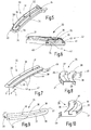
- the peculiarity of the instrument 10 lies in the design of the tool 15, which in FIG. 2 is separately illustrated.
- the tool 15 has two branches 16, 17, of which at least one, both in the present embodiment, are movably mounted on a base part 18.
- the base part 18 may for example consist of plastic, ceramic, composite material or metal.
- FIG. 3 the base part 18 is illustrated separately. It has a bearing portion 19 and an extension 20 extending away therefrom, which is inserted into the distal end of the shaft 12 and latched thereto by means of a latching lug 21.
- In the bearing portion 19 are two mutually parallel, to different flanks open substantially cylindrical bushings 22, 23 are formed, which are also open to the distal end of the base member 18 out. Between the two bushings 22, 23, a slot 24 may be provided, through which a knife for severing coagulated tissue, for example, sealed vessels, can be pushed.
- the inner hollow extension 20 may on the outside at its two flanks corrugated grooves 25 for receiving a have electrical line with which the electrode units 33 of the branches 16, 17 are supplied with voltage or current.
- the sectors 16, 17 each have an industry support 26, as he FIG. 4 is apparent.
- This can be made of plastic or metal. It is designed as a two-armed lever and has a tool part 27 and an actuating part 28. Between both a bearing portion 29 is arranged, which fits into the bearing bushes 22 or 23.
- the bearing portion 29 is formed substantially cylindrical. At one end face, it merges seamlessly into the flat flank of the eccentrically arranged actuating part 28.
- the bearing portion 29 is connected to the tool part 27 along a strip-shaped or segment-shaped region of its cylinder jacket. In this way, a safe and resilient pivotable mounting of the industry support 26 is given to the base part 18.
- an actuating pin 30 is held, which projects through a side window 31 into the interior of the extension 20. From there, an attaching to the actuating pin 30 Anlagen- / Schubstoff longitudinally pass through the shaft 12 into the housing 11 to move the industry support 26 by operating the operating lever 14 can.
- the tool part 27 has a receiving surface 32 for receiving an electrode unit 33, which consists of the FIGS. 5 and 6 evident.
- the electrode unit 33 consists of a plastic body 34 and a sheet metal part 35.
- the sheet metal part 35 is in the FIGS. 7 to 12 again separately illustrated.
- the sheet metal part 35 forms the electrode for introducing electrical current into a biological tissue. It has a preferably substantially flat tissue contact surface 36, which may be interrupted centrally by a longitudinal slot 37. Longitudinally extending flat sections of the tissue contact surface 36 extend on both sides of the longitudinal slot 37.
- the electrode unit 33 may be completely straight or, as shown in the figures, slightly curved to follow a curvature of the tool part 27. In the latter case, the longitudinal slot 37 is correspondingly curved, so that the elongate portions of the tissue contact surface 36 each have a substantially constant width on both sides thereof, as is apparent FIG. 9 evident.
- the tissue contact surface 36 has two long opposed edges 38, 39 from which strip portions 40, 41 extend angled away.
- the edges 38, 39 preferably form rounded transitions.
- the strip sections 40, 41 of the tissue contact surface 36 are preferably arranged substantially parallel to one another. They are, more preferably, along their entire length with openings 42 which are like FIG. 7 can recognize, for example, as slots 43 may be formed. These slots 43 are separated by webs 44 which are preferably at least as long as they are wide.
- the length is understood to be in a direction perpendicular to the tissue contact surface 36. This direction is marked by an arrow X in FIG.
- the width is understood to be parallel to the longitudinal slot 37.
- This direction is in FIG. 7 marked by an arrow Y
- the slots 43 have a dimension which is preferably substantially larger than their perpendicular dimension measured in the X direction.
- the strip portions 40, 41 may have different shapes.
- the formation of the strip sections is shown by way of example on the strip section 40 and can also apply to the strip section 41.
- the strip portion 40 has a substantially rectangular basic shape that extends away from the edge 38. This basic form is in the Figures 11 and 12 represented by a dashed line 56.
- the strip portion 40 may have slots 43 and openings 42 as described above and in FIGS FIGS. 7 and 8 have shown. Additionally or alternatively, the strip portion 40 may include apertures 42a, and slots 43a that define a shape extending away from the edge 38 of the tissue-contacting surface 36, in FIGS Figures 11 and 12 have downwardly open shape.
- the slots 43a are separated by webs 44, the above description of which applies mutatis mutandis.
- the openings 42 and 42a are designed so that they have holding means in the form of recesses 57 or undercuts 57, so that the plastic body 34 can be connected to the sheet metal part 35 by positive engagement.
- the webs 44 can also extend in sections in the Z direction ( FIG. 12 ). As FIG. 11 shows, it is also possible that a web 44a has a region which is executed twisted about its own axis.
- other embodiments of the webs 44, 44a, the openings 42,42a and the slots 43, 43a which serve the purpose of a positive connection between the plastic body 34 and the sheet metal part 35 are possible.
- recesses 45, 46 are formed, for example in the form of round holes.
- the sheet metal part 35 preferably has no strip section. If necessary, however, bent sections may also be present here away from the tissue contact surface 36 via a rounded edge.
- a terminal lug 49 may be formed on an angled section in order to fasten a connection lead in a material or form-fit manner, for example by soldering, welding or crimping.
- the plastic body 34 fills, as FIG. 6 shows the gap between the strip portions 40, 41 from.
- the plastic body 34 passes through the slots 43, 43 a or other openings 42, 42 a, which are formed in the strip portions 40, 41.
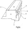
- the plastic body 34 forms an insulating region, such as an insulating step or shoulder 50, which provides a space between the tissue contact surface 36 and surrounding non-treatment tissue.
- the shoulder 50 has a substantially rectangular cross-section with a recess 59 arranged on the outside. In FIG. 6a the cross section of the shoulder 50 is indicated by dashed lines.
- the shoulder 50 Toward the tissue contact surface 36, the shoulder 50 has an attachment 60 running outside along the tissue contact surface 36, which terminates with a surface 58 placed deeper in relation to the tissue contact surface 36.
- this attachment 60 provides protection to the tissue against the tissue contact surface 36 and significantly prevents or reduces thermal changes in the tissue in the region of the shoulder 50 in tissue sealing.
- the recess 59 of the Shoulder 50 includes a concavely rounded portion such that the shoulder has a convexly curved portion 61. By the rounded convex curved portion 61, the tissue is securely held when closing the branches, without injuring it.
- the attachment 60 can also have a rounded outer area.
- the shoulder 50 may have a width and a height of 0.1 mm to 3 mm, preferably 0.5 mm.
- the coagulation effect can be confined to confined between the industries 16, 17 and compressed tissue.
- the tissue captured adjacent the tissue contact surfaces 36 between the shoulders 50 is less or not clamped.
- the above-described rounded portions of the shoulder 50 may also include other shapes, such as angled portions.
- the shoulder 50 is designed to be gentle on the tissue.
- the plastic body 34 also extends through the recesses 45, 46 and thus forms the tissue contact surface 36 protruding holding means 51, 52 (FIG. FIG. 5 ), which serve to securely hold tissue grasped between the tissue contact surfaces 36 even when it shrinks due to coagulation and dehydration.
- the holding means 51, 52 can also act as spacers to prevent a metallic contact of the tissue contact surfaces 36 of the electrode units 33 of the two branches 16, 17 and thus an electrical short circuit.
- the plastic body 34 Centrally in the longitudinal slot 37, the plastic body 34 has a knife guide groove 55. This is preferably significantly narrower than the longitudinal slot 37. A running in the Messer Overallsnut 55 knife is thus safe against the sheet metal part 35 electrically isolated.
- spacers 53, 54 may be provided, which are formed for example by emanating from the shoulder 50 projections of the plastic body 34 and project beyond the tissue contact surface 36. In the embodiment according to FIG. 5 These spacers 53, 54 are arranged at the distal end 47 of the electrode unit 33. Spacers 53, 54 may in other embodiments be disposed at other suitable locations on the electrode assembly 33 and may also form means for holding the tissue.
- the instrument 10 described so far operates as follows: The instrument 10 is first connected with its connecting cable with a feeding not further illustrated device or generator. The user can then grasp biological tissue, for example vessels or vascular bundles, between the tissue contact surfaces 36 of the branches 16, 17 of the tool 15 and clamp them by actuating the operating lever 14. By actuating a switch not further illustrated, it can now apply an electrical voltage, for example HF voltage, to the tissue contact surfaces 36 of the electrode units 33 of the two branches 16, 17, whereby the clamped vessel is flowed through electrically. As a result, coagulation and fusion of opposing vessel walls can be achieved.
- a knife is also present. This can be activated, wherein it is advanced in the Messer Elisnut 55 in the distal direction and thereby cuts the intermediate coagulated and sealed vessel.
- the instrument 10 may be disposed of or recycled. It is also possible to sterilize only parts or the entire instrument 10.
- the surgical instrument 10 is particularly suitable for tissue sealing. It comprises a tool 15 which has at least one branch 16 with an electrode unit 33.
- This consists of a sheet metal part 35, which is preferably formed as a stamped and bent part and positively anchored in a preferably formed as an injection molded plastic body 34.
- the extending into the plastic body 34 parts, in particular strip portions 40, 41, have generously dimensioned openings 42 through which the plastic body 34 extends.
- the heat capacity of the sheet metal part 35, as well as the thermal conductivity of the plastic body 34 is low, so that even after short consecutive repeated use, regardless of the initial temperature of the tissue contact surfaces 36, consistently good coagulation results can be achieved.
Landscapes
- Health & Medical Sciences (AREA)
- Surgery (AREA)
- Engineering & Computer Science (AREA)
- Life Sciences & Earth Sciences (AREA)
- Biomedical Technology (AREA)
- Molecular Biology (AREA)
- Nuclear Medicine, Radiotherapy & Molecular Imaging (AREA)
- Plasma & Fusion (AREA)
- Physics & Mathematics (AREA)
- Heart & Thoracic Surgery (AREA)
- Medical Informatics (AREA)
- Otolaryngology (AREA)
- Animal Behavior & Ethology (AREA)
- General Health & Medical Sciences (AREA)
- Public Health (AREA)
- Veterinary Medicine (AREA)
- Surgical Instruments (AREA)
- Connection Of Plates (AREA)
Claims (13)
- Instrument chirurgical (10), destiné notamment à la fusion tissulaire,
comprenant un outil (15) qui présente au moins un mors (16) avec une unité d'électrode (33),
dans lequel l'unité d'électrode (33) est constituée d'une pièce en tôle (35) et d'un corps en matière plastique (34), et dans lequel- la pièce en tôle (35) présente une surface de contact de tissu (36) comportant deux bords (38, 39) longitudinaux situés en vis-à-vis l'un de l'autre,- des portions de bande (40, 41) coudées s'étendent à partir des bords (38, 39),- des ouvertures (42) sont prévues dans les portions de bande (40, 41),- le corps en matière plastique (34) remplit un espace formé entre les portions de bande (40, 41),
caractérisé en ce que- le corps en matière plastique (34) traverse les ouvertures (42, 42a) en passant à travers les ouvertures (42, 42a),- et en ce que le corps en matière plastique (34) présente, sur les faces externes des portions de bande (40, 41), une zone isolante (50) comportant une partie saillante (60) qui s'étend à l'extérieur le long de la surface de contact de tissu (36), en direction de la surface de contact de tissu (36), et qui se termine par une surface (58) disposée plus bas par rapport à la surface de contact de tissu (36). - Instrument selon la revendication 1, caractérisé en ce que les ouvertures (42) sont des fentes (43).
- Instrument selon la revendication 2, caractérisé en ce que les fentes (43) sont séparées les unes des autres par des barrettes (44, 44a), la superficie des ouvertures (42, 42a) étant plus grande que la superficie des barrettes (44, 44a).
- Instrument selon la revendication 3, caractérisé en ce que le rapport entre les superficies des ouvertures (42, 42a) et les superficies des barrettes (44, 44a) va de 3 à 1 jusqu'à 20 à 1 et est de préférence de 10 à 1.
- Instrument selon une des revendications précédentes, caractérisé en ce que la surface de contact de tissu (36) est interrompue par une fente longitudinale (37).
- Instrument selon la revendication 5, caractérisé en ce que le corps en matière plastique (34) présente une rainure de guidage de lame (55), dans une disposition alignée avec la fente longitudinale (37).
- Instrument selon la revendication 6, caractérisé en ce que la fente longitudinale (37) est plus large que la rainure de guidage de lame (55).
- Instrument selon une des revendications précédentes, caractérisé en ce que la pièce en tôle (35) est une pièce façonnée par formage ou cintrage.
- Instrument selon une des revendications précédentes, caractérisé en ce que la surface de contact de tissu (36) présente des évidements (45, 46) à travers lesquels s'étend le corps en matière plastique (34) pour former des moyens de maintien (51, 52).
- Instrument selon la revendication 9, caractérisé en ce que les moyens de maintien (51, 52) sont décalés de part et d'autre d'une fente longitudinale (37).
- Instrument selon la revendication 9, caractérisé en ce qu'un moyen de maintien (51, 52) présente une dimension de surface comprise dans la plage allant de 0,5 mm2 à 7 mm2.
- Instrument selon la revendication 11, caractérisé en ce qu'un moyen de maintien (51, 52) est réalisé de façon à occuper une superficie de 0,75 mm2.
- Instrument selon une des revendications précédentes, caractérisé en ce que des éléments d'espacement (53, 54) sont disposés sur le bord de la surface de contact de tissu (36).
Priority Applications (11)
| Application Number | Priority Date | Filing Date | Title |
|---|---|---|---|
| EP18157385.8A EP3351198B1 (fr) | 2013-09-10 | 2013-09-12 | Instrument de scellement des vaisseaux |
| EP13184185.0A EP2853219B1 (fr) | 2013-09-10 | 2013-09-12 | Instrument permettant de sceller un vaisseau |
| PL18157385T PL3351198T3 (pl) | 2013-09-10 | 2013-09-12 | Instrument do zamykania naczyń |
| PL13184185T PL2853219T3 (pl) | 2013-09-10 | 2013-09-12 | Instrument do zamykania naczyń |
| BR102014021107-1A BR102014021107B1 (pt) | 2013-09-12 | 2014-08-27 | instrumento cirúrgico para a ligação de tecidos |
| KR1020140117526A KR101629086B1 (ko) | 2013-09-10 | 2014-09-04 | 혈관을 봉합하기 위한 기구 |
| RU2014136541/14A RU2585417C2 (ru) | 2013-09-10 | 2014-09-09 | Хирургический инструмент |
| CN201410457145.4A CN104414741A (zh) | 2013-09-10 | 2014-09-10 | 用于密封脉管的器具 |
| CN201910261951.7A CN110013305B (zh) | 2013-09-10 | 2014-09-10 | 用于密封脉管的器具 |
| US14/482,224 US10314643B2 (en) | 2013-09-10 | 2014-09-10 | Instrument for sealing vessels |
| JP2014184603A JP6106140B2 (ja) | 2013-09-10 | 2014-09-10 | 血管シール器具 |
Applications Claiming Priority (2)
| Application Number | Priority Date | Filing Date | Title |
|---|---|---|---|
| EP13183641 | 2013-09-10 | ||
| EP13184185.0A EP2853219B1 (fr) | 2013-09-10 | 2013-09-12 | Instrument permettant de sceller un vaisseau |
Related Child Applications (2)
| Application Number | Title | Priority Date | Filing Date |
|---|---|---|---|
| EP18157385.8A Division EP3351198B1 (fr) | 2013-09-10 | 2013-09-12 | Instrument de scellement des vaisseaux |
| EP18157385.8A Division-Into EP3351198B1 (fr) | 2013-09-10 | 2013-09-12 | Instrument de scellement des vaisseaux |
Publications (2)
| Publication Number | Publication Date |
|---|---|
| EP2853219A1 EP2853219A1 (fr) | 2015-04-01 |
| EP2853219B1 true EP2853219B1 (fr) | 2018-06-06 |
Family
ID=49118413
Family Applications (2)
| Application Number | Title | Priority Date | Filing Date |
|---|---|---|---|
| EP13184185.0A Revoked EP2853219B1 (fr) | 2013-09-10 | 2013-09-12 | Instrument permettant de sceller un vaisseau |
| EP18157385.8A Active EP3351198B1 (fr) | 2013-09-10 | 2013-09-12 | Instrument de scellement des vaisseaux |
Family Applications After (1)
| Application Number | Title | Priority Date | Filing Date |
|---|---|---|---|
| EP18157385.8A Active EP3351198B1 (fr) | 2013-09-10 | 2013-09-12 | Instrument de scellement des vaisseaux |
Country Status (7)
| Country | Link |
|---|---|
| US (1) | US10314643B2 (fr) |
| EP (2) | EP2853219B1 (fr) |
| JP (1) | JP6106140B2 (fr) |
| KR (1) | KR101629086B1 (fr) |
| CN (2) | CN110013305B (fr) |
| PL (2) | PL2853219T3 (fr) |
| RU (1) | RU2585417C2 (fr) |
Families Citing this family (5)
| Publication number | Priority date | Publication date | Assignee | Title |
|---|---|---|---|---|
| PL2853219T3 (pl) | 2013-09-10 | 2018-09-28 | Erbe Elektromedizin | Instrument do zamykania naczyń |
| CN106420046A (zh) * | 2016-09-30 | 2017-02-22 | 北京迈迪顶峰医疗科技有限公司 | 一种一体化电极 |
| US11806068B2 (en) | 2020-12-15 | 2023-11-07 | Covidien Lp | Energy-based surgical instrument for grasping, treating, and/or dividing tissue |
| US12059196B2 (en) | 2020-12-15 | 2024-08-13 | Covidien Lp | Energy-based surgical instrument for grasping, treating, and/or dividing tissue |
| EP4371515A1 (fr) | 2022-11-21 | 2024-05-22 | Erbe Elektromedizin GmbH | Instrument de coagulation |
Citations (7)
| Publication number | Priority date | Publication date | Assignee | Title |
|---|---|---|---|---|
| US20110073246A1 (en) | 2009-09-28 | 2011-03-31 | Tyco Healthcare Group Lp | Method and System for Manufacturing Electrosurgical Seal Plates |
| EP2377480A1 (fr) | 2010-04-13 | 2011-10-19 | Tyco Healthcare Group, LP | Contrôle de la température de plaque de scellage |
| EP2436330A1 (fr) | 2010-10-04 | 2012-04-04 | Tyco Healthcare Group, LP | Instrument d'obturation des vaisseaux |
| US20120083784A1 (en) | 2010-10-01 | 2012-04-05 | Ethicon Endo-Surgery, Inc. | Surgical instrument with jaw member |
| US20120172873A1 (en) | 2010-10-04 | 2012-07-05 | Tyco Healthcare Group Lp | Vessel Sealing Instrument |
| US20130046303A1 (en) | 2011-08-18 | 2013-02-21 | Tyco Healthcare Group Lp | Surgical Forceps |
| EP2853219A1 (fr) | 2013-09-10 | 2015-04-01 | Erbe Elektromedizin GmbH | Instrument permettant de sceller un vaisseau |
Family Cites Families (20)
| Publication number | Priority date | Publication date | Assignee | Title |
|---|---|---|---|---|
| US3774615A (en) * | 1971-02-08 | 1973-11-27 | Ceskoslovenska Akademie Ved | Device for connecting or joining the ends of interrupted tubular organs in surgical operations without stitching |
| US4552148A (en) * | 1981-07-27 | 1985-11-12 | American Cyanamid Company | Anastomotic device |
| SU1528463A1 (ru) * | 1987-03-26 | 1989-12-15 | Всесоюзный научно-исследовательский и испытательный институт медицинской техники | Скобочный магазин к хирургическим сшивающим аппаратам |
| SU1560138A1 (ru) * | 1988-06-01 | 1990-04-30 | Украинский Институт Усовершенствования Врачей | Аппарат дл ушивани органов и сосудов |
| WO2002080796A1 (fr) | 2001-04-06 | 2002-10-17 | Sherwood Services Ag | Obturateur et separateur de vaisseau equipe d'elements de butee non conducteurs |
| CA2442706A1 (fr) * | 2001-04-06 | 2002-10-17 | Sherwood Services Ag | Instrument electro-chirurgical reduisant le contournement |
| US7877853B2 (en) * | 2007-09-20 | 2011-02-01 | Tyco Healthcare Group Lp | Method of manufacturing end effector assembly for sealing tissue |
| DE102008019380B4 (de) * | 2008-04-17 | 2012-11-22 | Erbe Elektromedizin Gmbh | Bipolare Klemme für die HF-Chirurgie |
| US8277446B2 (en) | 2009-04-24 | 2012-10-02 | Tyco Healthcare Group Lp | Electrosurgical tissue sealer and cutter |
| DE102010016291A1 (de) | 2010-04-01 | 2011-10-06 | Erbe Elektromedizin Gmbh | Chirurgisches Instrument, insbesondere elektrochirurgisches Instrument |
| EP3300678A1 (fr) * | 2011-02-18 | 2018-04-04 | Intuitive Surgical Operations Inc. | Instrument chirurgical de coupe et de fusion et procédés associés |
| US9039732B2 (en) | 2011-07-11 | 2015-05-26 | Covidien Lp | Surgical forceps |
| US9028492B2 (en) * | 2011-08-18 | 2015-05-12 | Covidien Lp | Surgical instruments with removable components |
| US8968317B2 (en) * | 2011-08-18 | 2015-03-03 | Covidien Lp | Surgical forceps |
| US20130071282A1 (en) | 2011-09-19 | 2013-03-21 | Tyco Healthcare Group Lp | Method For Securing A Stop Member To A Seal Plate Configured For Use With An Electrosurgical Instrument |
| CN202313713U (zh) * | 2011-11-09 | 2012-07-11 | 常州市延陵电子设备有限公司 | 血管闭合系统用钳头 |
| US9113882B2 (en) * | 2012-01-23 | 2015-08-25 | Covidien Lp | Method of manufacturing an electrosurgical instrument |
| US8747434B2 (en) | 2012-02-20 | 2014-06-10 | Covidien Lp | Knife deployment mechanisms for surgical forceps |
| US9153180B2 (en) * | 2012-06-29 | 2015-10-06 | Samsung Display Co., Ltd. | Multi primary color display device and method of driving the same |
| US8939975B2 (en) * | 2012-07-17 | 2015-01-27 | Covidien Lp | Gap control via overmold teeth and hard stops |
-
2013
- 2013-09-12 PL PL13184185T patent/PL2853219T3/pl unknown
- 2013-09-12 EP EP13184185.0A patent/EP2853219B1/fr not_active Revoked
- 2013-09-12 EP EP18157385.8A patent/EP3351198B1/fr active Active
- 2013-09-12 PL PL18157385T patent/PL3351198T3/pl unknown
-
2014
- 2014-09-04 KR KR1020140117526A patent/KR101629086B1/ko active IP Right Grant
- 2014-09-09 RU RU2014136541/14A patent/RU2585417C2/ru active
- 2014-09-10 JP JP2014184603A patent/JP6106140B2/ja active Active
- 2014-09-10 CN CN201910261951.7A patent/CN110013305B/zh active Active
- 2014-09-10 US US14/482,224 patent/US10314643B2/en active Active
- 2014-09-10 CN CN201410457145.4A patent/CN104414741A/zh active Pending
Patent Citations (7)
| Publication number | Priority date | Publication date | Assignee | Title |
|---|---|---|---|---|
| US20110073246A1 (en) | 2009-09-28 | 2011-03-31 | Tyco Healthcare Group Lp | Method and System for Manufacturing Electrosurgical Seal Plates |
| EP2377480A1 (fr) | 2010-04-13 | 2011-10-19 | Tyco Healthcare Group, LP | Contrôle de la température de plaque de scellage |
| US20120083784A1 (en) | 2010-10-01 | 2012-04-05 | Ethicon Endo-Surgery, Inc. | Surgical instrument with jaw member |
| EP2436330A1 (fr) | 2010-10-04 | 2012-04-04 | Tyco Healthcare Group, LP | Instrument d'obturation des vaisseaux |
| US20120172873A1 (en) | 2010-10-04 | 2012-07-05 | Tyco Healthcare Group Lp | Vessel Sealing Instrument |
| US20130046303A1 (en) | 2011-08-18 | 2013-02-21 | Tyco Healthcare Group Lp | Surgical Forceps |
| EP2853219A1 (fr) | 2013-09-10 | 2015-04-01 | Erbe Elektromedizin GmbH | Instrument permettant de sceller un vaisseau |
Also Published As
| Publication number | Publication date |
|---|---|
| CN110013305B (zh) | 2022-05-27 |
| KR101629086B1 (ko) | 2016-06-09 |
| EP3351198A1 (fr) | 2018-07-25 |
| RU2014136541A (ru) | 2016-03-27 |
| PL2853219T3 (pl) | 2018-09-28 |
| EP3351198B1 (fr) | 2019-08-14 |
| CN110013305A (zh) | 2019-07-16 |
| JP2015054248A (ja) | 2015-03-23 |
| US10314643B2 (en) | 2019-06-11 |
| CN104414741A (zh) | 2015-03-18 |
| KR20150029564A (ko) | 2015-03-18 |
| RU2585417C2 (ru) | 2016-05-27 |
| JP6106140B2 (ja) | 2017-03-29 |
| US20150073408A1 (en) | 2015-03-12 |
| EP2853219A1 (fr) | 2015-04-01 |
| PL3351198T3 (pl) | 2019-11-29 |
Similar Documents
| Publication | Publication Date | Title |
|---|---|---|
| DE102016100588B4 (de) | Elektrochirurgisches Instrument mit elektrisch leitfähigen Anschlagelementen und Verfahren zur Herstellung eines Backenelements für ein elektrochirurgisches Instrument | |
| EP2777583B1 (fr) | Instrument de fusion et de séparation de récipients | |
| EP2959854B1 (fr) | Instrument chirurgical | |
| EP2853219B1 (fr) | Instrument permettant de sceller un vaisseau | |
| EP1778112B1 (fr) | Instrument electro-chirurgical | |
| EP1153578B1 (fr) | Instrument chirurgical en forme de pince ou de ciseaux | |
| DE102011102369B4 (de) | Symmetrisches Elektroden-Umschaltverfahren und zugehöriges System | |
| EP1793755B1 (fr) | Instrument electrochirurgical | |
| DE10201569B4 (de) | Chirurgisches Instrument | |
| DE69719581T2 (de) | Bipolare Schere | |
| DE60029691T2 (de) | Verbessertes, mit radiofrequenz arbeitendes, bipolares endstück zur anwendung in elektrochirurgischen instrumenten | |
| DE60312348T2 (de) | Elektrodenanordnung zum versiegeln und schneiden von gewebe | |
| DE102008030285A1 (de) | Elektrochirurgisches Instrument | |
| EP2522291B1 (fr) | Instrument électrochirurgical | |
| EP2679186B1 (fr) | Instrument de fusion et de séparation des tissus | |
| EP3437581B1 (fr) | Unité d'électrode pour un résectoscope médical | |
| DE20002645U1 (de) | Medizinisches bipolares Instrument zum Schneiden von Gewebe | |
| DE202012001295U1 (de) | Elektrochirurgische Vorrichtung zur Feindissektion | |
| EP2982325B1 (fr) | Procédé de fabrication d'une branche et d'un instrument chirurgical doté d'un outil présentant une branche | |
| EP2845548B1 (fr) | Instrument chirurgical des mors pivotants | |
| EP3075340B1 (fr) | Ciseaux chirurgicaux pour tissus biologiques | |
| DE102007062939A1 (de) | Schneid- u. Koagulationselektrode | |
| WO2001022896A1 (fr) | Instrument medical bipolaire servant a couper des tissus | |
| EP1891907A1 (fr) | Dispositif destiné à la résection et/ou l'ablation de tissus organiques à l'aide d'une énergie haute fréquence tout comme résectoscope | |
| DE102011079494A1 (de) | Elektrochirurgisches Greifinstrument |
Legal Events
| Date | Code | Title | Description |
|---|---|---|---|
| PUAI | Public reference made under article 153(3) epc to a published international application that has entered the european phase |
Free format text: ORIGINAL CODE: 0009012 |
|
| 17P | Request for examination filed |
Effective date: 20130912 |
|
| AK | Designated contracting states |
Kind code of ref document: A1 Designated state(s): AL AT BE BG CH CY CZ DE DK EE ES FI FR GB GR HR HU IE IS IT LI LT LU LV MC MK MT NL NO PL PT RO RS SE SI SK SM TR |
|
| AX | Request for extension of the european patent |
Extension state: BA ME |
|
| R17P | Request for examination filed (corrected) |
Effective date: 20150417 |
|
| RBV | Designated contracting states (corrected) |
Designated state(s): AL AT BE BG CH CY CZ DE DK EE ES FI FR GB GR HR HU IE IS IT LI LT LU LV MC MK MT NL NO PL PT RO RS SE SI SK SM TR |
|
| RAP1 | Party data changed (applicant data changed or rights of an application transferred) |
Owner name: ERBE ELEKTROMEDIZIN GMBH |
|
| GRAP | Despatch of communication of intention to grant a patent |
Free format text: ORIGINAL CODE: EPIDOSNIGR1 |
|
| STAA | Information on the status of an ep patent application or granted ep patent |
Free format text: STATUS: GRANT OF PATENT IS INTENDED |
|
| INTG | Intention to grant announced |
Effective date: 20171221 |
|
| GRAS | Grant fee paid |
Free format text: ORIGINAL CODE: EPIDOSNIGR3 |
|
| GRAJ | Information related to disapproval of communication of intention to grant by the applicant or resumption of examination proceedings by the epo deleted |
Free format text: ORIGINAL CODE: EPIDOSDIGR1 |
|
| GRAL | Information related to payment of fee for publishing/printing deleted |
Free format text: ORIGINAL CODE: EPIDOSDIGR3 |
|
| STAA | Information on the status of an ep patent application or granted ep patent |
Free format text: STATUS: REQUEST FOR EXAMINATION WAS MADE |
|
| INTC | Intention to grant announced (deleted) | ||
| GRAR | Information related to intention to grant a patent recorded |
Free format text: ORIGINAL CODE: EPIDOSNIGR71 |
|
| STAA | Information on the status of an ep patent application or granted ep patent |
Free format text: STATUS: GRANT OF PATENT IS INTENDED |
|
| GRAA | (expected) grant |
Free format text: ORIGINAL CODE: 0009210 |
|
| STAA | Information on the status of an ep patent application or granted ep patent |
Free format text: STATUS: THE PATENT HAS BEEN GRANTED |
|
| AK | Designated contracting states |
Kind code of ref document: B1 Designated state(s): AL AT BE BG CH CY CZ DE DK EE ES FI FR GB GR HR HU IE IS IT LI LT LU LV MC MK MT NL NO PL PT RO RS SE SI SK SM TR |
|
| INTG | Intention to grant announced |
Effective date: 20180427 |
|
| REG | Reference to a national code |
Ref country code: GB Ref legal event code: FG4D Free format text: NOT ENGLISH |
|
| RIN2 | Information on inventor provided after grant (corrected) |
Inventor name: SCHAELLER, DANIEL Inventor name: AMANN, MARCUS Inventor name: MAYER, VOLKER Inventor name: DUEPPUIS, MARTINA |
|
| REG | Reference to a national code |
Ref country code: CH Ref legal event code: EP Ref country code: AT Ref legal event code: REF Ref document number: 1005193 Country of ref document: AT Kind code of ref document: T Effective date: 20180615 |
|
| REG | Reference to a national code |
Ref country code: IE Ref legal event code: FG4D Free format text: LANGUAGE OF EP DOCUMENT: GERMAN |
|
| REG | Reference to a national code |
Ref country code: DE Ref legal event code: R096 Ref document number: 502013010314 Country of ref document: DE |
|
| REG | Reference to a national code |
Ref country code: FR Ref legal event code: PLFP Year of fee payment: 6 |
|
| REG | Reference to a national code |
Ref country code: NL Ref legal event code: MP Effective date: 20180606 |
|
| REG | Reference to a national code |
Ref country code: LT Ref legal event code: MG4D |
|
| PG25 | Lapsed in a contracting state [announced via postgrant information from national office to epo] |
Ref country code: LT Free format text: LAPSE BECAUSE OF FAILURE TO SUBMIT A TRANSLATION OF THE DESCRIPTION OR TO PAY THE FEE WITHIN THE PRESCRIBED TIME-LIMIT Effective date: 20180606 Ref country code: ES Free format text: LAPSE BECAUSE OF FAILURE TO SUBMIT A TRANSLATION OF THE DESCRIPTION OR TO PAY THE FEE WITHIN THE PRESCRIBED TIME-LIMIT Effective date: 20180606 Ref country code: CY Free format text: LAPSE BECAUSE OF FAILURE TO SUBMIT A TRANSLATION OF THE DESCRIPTION OR TO PAY THE FEE WITHIN THE PRESCRIBED TIME-LIMIT Effective date: 20180606 Ref country code: BG Free format text: LAPSE BECAUSE OF FAILURE TO SUBMIT A TRANSLATION OF THE DESCRIPTION OR TO PAY THE FEE WITHIN THE PRESCRIBED TIME-LIMIT Effective date: 20180906 Ref country code: FI Free format text: LAPSE BECAUSE OF FAILURE TO SUBMIT A TRANSLATION OF THE DESCRIPTION OR TO PAY THE FEE WITHIN THE PRESCRIBED TIME-LIMIT Effective date: 20180606 Ref country code: NO Free format text: LAPSE BECAUSE OF FAILURE TO SUBMIT A TRANSLATION OF THE DESCRIPTION OR TO PAY THE FEE WITHIN THE PRESCRIBED TIME-LIMIT Effective date: 20180906 Ref country code: SE Free format text: LAPSE BECAUSE OF FAILURE TO SUBMIT A TRANSLATION OF THE DESCRIPTION OR TO PAY THE FEE WITHIN THE PRESCRIBED TIME-LIMIT Effective date: 20180606 |
|
| PG25 | Lapsed in a contracting state [announced via postgrant information from national office to epo] |
Ref country code: GR Free format text: LAPSE BECAUSE OF FAILURE TO SUBMIT A TRANSLATION OF THE DESCRIPTION OR TO PAY THE FEE WITHIN THE PRESCRIBED TIME-LIMIT Effective date: 20180907 Ref country code: LV Free format text: LAPSE BECAUSE OF FAILURE TO SUBMIT A TRANSLATION OF THE DESCRIPTION OR TO PAY THE FEE WITHIN THE PRESCRIBED TIME-LIMIT Effective date: 20180606 Ref country code: RS Free format text: LAPSE BECAUSE OF FAILURE TO SUBMIT A TRANSLATION OF THE DESCRIPTION OR TO PAY THE FEE WITHIN THE PRESCRIBED TIME-LIMIT Effective date: 20180606 Ref country code: HR Free format text: LAPSE BECAUSE OF FAILURE TO SUBMIT A TRANSLATION OF THE DESCRIPTION OR TO PAY THE FEE WITHIN THE PRESCRIBED TIME-LIMIT Effective date: 20180606 |
|
| PG25 | Lapsed in a contracting state [announced via postgrant information from national office to epo] |
Ref country code: NL Free format text: LAPSE BECAUSE OF FAILURE TO SUBMIT A TRANSLATION OF THE DESCRIPTION OR TO PAY THE FEE WITHIN THE PRESCRIBED TIME-LIMIT Effective date: 20180606 |
|
| PG25 | Lapsed in a contracting state [announced via postgrant information from national office to epo] |
Ref country code: CZ Free format text: LAPSE BECAUSE OF FAILURE TO SUBMIT A TRANSLATION OF THE DESCRIPTION OR TO PAY THE FEE WITHIN THE PRESCRIBED TIME-LIMIT Effective date: 20180606 Ref country code: SK Free format text: LAPSE BECAUSE OF FAILURE TO SUBMIT A TRANSLATION OF THE DESCRIPTION OR TO PAY THE FEE WITHIN THE PRESCRIBED TIME-LIMIT Effective date: 20180606 Ref country code: RO Free format text: LAPSE BECAUSE OF FAILURE TO SUBMIT A TRANSLATION OF THE DESCRIPTION OR TO PAY THE FEE WITHIN THE PRESCRIBED TIME-LIMIT Effective date: 20180606 Ref country code: EE Free format text: LAPSE BECAUSE OF FAILURE TO SUBMIT A TRANSLATION OF THE DESCRIPTION OR TO PAY THE FEE WITHIN THE PRESCRIBED TIME-LIMIT Effective date: 20180606 Ref country code: IS Free format text: LAPSE BECAUSE OF FAILURE TO SUBMIT A TRANSLATION OF THE DESCRIPTION OR TO PAY THE FEE WITHIN THE PRESCRIBED TIME-LIMIT Effective date: 20181006 |
|
| REG | Reference to a national code |
Ref country code: DE Ref legal event code: R026 Ref document number: 502013010314 Country of ref document: DE |
|
| PG25 | Lapsed in a contracting state [announced via postgrant information from national office to epo] |
Ref country code: SM Free format text: LAPSE BECAUSE OF FAILURE TO SUBMIT A TRANSLATION OF THE DESCRIPTION OR TO PAY THE FEE WITHIN THE PRESCRIBED TIME-LIMIT Effective date: 20180606 |
|
| PLBI | Opposition filed |
Free format text: ORIGINAL CODE: 0009260 |
|
| PLBI | Opposition filed |
Free format text: ORIGINAL CODE: 0009260 |
|
| PLAX | Notice of opposition and request to file observation + time limit sent |
Free format text: ORIGINAL CODE: EPIDOSNOBS2 |
|
| 26 | Opposition filed |
Opponent name: BOWA-ELECTRONIC GMBH & CO. KG Effective date: 20190227 |
|
| 26 | Opposition filed |
Opponent name: KLS MARTIN GMBH + CO. KG Effective date: 20190306 |
|
| PG25 | Lapsed in a contracting state [announced via postgrant information from national office to epo] |
Ref country code: MC Free format text: LAPSE BECAUSE OF FAILURE TO SUBMIT A TRANSLATION OF THE DESCRIPTION OR TO PAY THE FEE WITHIN THE PRESCRIBED TIME-LIMIT Effective date: 20180606 |
|
| REG | Reference to a national code |
Ref country code: CH Ref legal event code: PL |
|
| PG25 | Lapsed in a contracting state [announced via postgrant information from national office to epo] |
Ref country code: SI Free format text: LAPSE BECAUSE OF FAILURE TO SUBMIT A TRANSLATION OF THE DESCRIPTION OR TO PAY THE FEE WITHIN THE PRESCRIBED TIME-LIMIT Effective date: 20180606 Ref country code: DK Free format text: LAPSE BECAUSE OF FAILURE TO SUBMIT A TRANSLATION OF THE DESCRIPTION OR TO PAY THE FEE WITHIN THE PRESCRIBED TIME-LIMIT Effective date: 20180606 |
|
| REG | Reference to a national code |
Ref country code: BE Ref legal event code: MM Effective date: 20180930 |
|
| REG | Reference to a national code |
Ref country code: IE Ref legal event code: MM4A |
|
| PG25 | Lapsed in a contracting state [announced via postgrant information from national office to epo] |
Ref country code: LU Free format text: LAPSE BECAUSE OF NON-PAYMENT OF DUE FEES Effective date: 20180912 |
|
| PLBB | Reply of patent proprietor to notice(s) of opposition received |
Free format text: ORIGINAL CODE: EPIDOSNOBS3 |
|
| PG25 | Lapsed in a contracting state [announced via postgrant information from national office to epo] |
Ref country code: IE Free format text: LAPSE BECAUSE OF NON-PAYMENT OF DUE FEES Effective date: 20180912 |
|
| PG25 | Lapsed in a contracting state [announced via postgrant information from national office to epo] |
Ref country code: CH Free format text: LAPSE BECAUSE OF NON-PAYMENT OF DUE FEES Effective date: 20180930 Ref country code: BE Free format text: LAPSE BECAUSE OF NON-PAYMENT OF DUE FEES Effective date: 20180930 Ref country code: LI Free format text: LAPSE BECAUSE OF NON-PAYMENT OF DUE FEES Effective date: 20180930 |
|
| PGFP | Annual fee paid to national office [announced via postgrant information from national office to epo] |
Ref country code: IT Payment date: 20190923 Year of fee payment: 7 Ref country code: FR Payment date: 20190926 Year of fee payment: 7 |
|
| REG | Reference to a national code |
Ref country code: AT Ref legal event code: MM01 Ref document number: 1005193 Country of ref document: AT Kind code of ref document: T Effective date: 20180912 |
|
| PG25 | Lapsed in a contracting state [announced via postgrant information from national office to epo] |
Ref country code: AL Free format text: LAPSE BECAUSE OF FAILURE TO SUBMIT A TRANSLATION OF THE DESCRIPTION OR TO PAY THE FEE WITHIN THE PRESCRIBED TIME-LIMIT Effective date: 20180606 |
|
| PGFP | Annual fee paid to national office [announced via postgrant information from national office to epo] |
Ref country code: PL Payment date: 20190828 Year of fee payment: 7 |
|
| PGFP | Annual fee paid to national office [announced via postgrant information from national office to epo] |
Ref country code: GB Payment date: 20190930 Year of fee payment: 7 |
|
| PG25 | Lapsed in a contracting state [announced via postgrant information from national office to epo] |
Ref country code: MT Free format text: LAPSE BECAUSE OF FAILURE TO SUBMIT A TRANSLATION OF THE DESCRIPTION OR TO PAY THE FEE WITHIN THE PRESCRIBED TIME-LIMIT Effective date: 20180606 Ref country code: AT Free format text: LAPSE BECAUSE OF NON-PAYMENT OF DUE FEES Effective date: 20180912 |
|
| PGFP | Annual fee paid to national office [announced via postgrant information from national office to epo] |
Ref country code: DE Payment date: 20191129 Year of fee payment: 7 |
|
| RDAF | Communication despatched that patent is revoked |
Free format text: ORIGINAL CODE: EPIDOSNREV1 |
|
| REG | Reference to a national code |
Ref country code: DE Ref legal event code: R064 Ref document number: 502013010314 Country of ref document: DE Ref country code: DE Ref legal event code: R103 Ref document number: 502013010314 Country of ref document: DE |
|
| PG25 | Lapsed in a contracting state [announced via postgrant information from national office to epo] |
Ref country code: TR Free format text: LAPSE BECAUSE OF FAILURE TO SUBMIT A TRANSLATION OF THE DESCRIPTION OR TO PAY THE FEE WITHIN THE PRESCRIBED TIME-LIMIT Effective date: 20180606 |
|
| PG25 | Lapsed in a contracting state [announced via postgrant information from national office to epo] |
Ref country code: HU Free format text: LAPSE BECAUSE OF FAILURE TO SUBMIT A TRANSLATION OF THE DESCRIPTION OR TO PAY THE FEE WITHIN THE PRESCRIBED TIME-LIMIT; INVALID AB INITIO Effective date: 20130912 Ref country code: PT Free format text: LAPSE BECAUSE OF FAILURE TO SUBMIT A TRANSLATION OF THE DESCRIPTION OR TO PAY THE FEE WITHIN THE PRESCRIBED TIME-LIMIT Effective date: 20180606 |
|
| PG25 | Lapsed in a contracting state [announced via postgrant information from national office to epo] |
Ref country code: MK Free format text: LAPSE BECAUSE OF NON-PAYMENT OF DUE FEES Effective date: 20180606 |
|
| RDAG | Patent revoked |
Free format text: ORIGINAL CODE: 0009271 |
|
| STAA | Information on the status of an ep patent application or granted ep patent |
Free format text: STATUS: PATENT REVOKED |
|
| REG | Reference to a national code |
Ref country code: FI Ref legal event code: MGE |
|
| 27W | Patent revoked |
Effective date: 20200301 |
|
| GBPR | Gb: patent revoked under art. 102 of the ep convention designating the uk as contracting state |
Effective date: 20200301 |
|
| REG | Reference to a national code |
Ref country code: AT Ref legal event code: MA03 Ref document number: 1005193 Country of ref document: AT Kind code of ref document: T Effective date: 20200301 |