EP2852964B1 - Kathodenfilamentanordnung - Google Patents
Kathodenfilamentanordnung Download PDFInfo
- Publication number
- EP2852964B1 EP2852964B1 EP13734502.1A EP13734502A EP2852964B1 EP 2852964 B1 EP2852964 B1 EP 2852964B1 EP 13734502 A EP13734502 A EP 13734502A EP 2852964 B1 EP2852964 B1 EP 2852964B1
- Authority
- EP
- European Patent Office
- Prior art keywords
- filament
- frame structure
- cathode
- support
- support structure
- Prior art date
- Legal status (The legal status is an assumption and is not a legal conclusion. Google has not performed a legal analysis and makes no representation as to the accuracy of the status listed.)
- Active
Links
Images


Classifications
-
- H—ELECTRICITY
- H01—ELECTRIC ELEMENTS
- H01J—ELECTRIC DISCHARGE TUBES OR DISCHARGE LAMPS
- H01J35/00—X-ray tubes
- H01J35/02—Details
- H01J35/04—Electrodes ; Mutual position thereof; Constructional adaptations therefor
- H01J35/06—Cathodes
- H01J35/064—Details of the emitter, e.g. material or structure
-
- H—ELECTRICITY
- H01—ELECTRIC ELEMENTS
- H01J—ELECTRIC DISCHARGE TUBES OR DISCHARGE LAMPS
- H01J1/00—Details of electrodes, of magnetic control means, of screens, or of the mounting or spacing thereof, common to two or more basic types of discharge tubes or lamps
- H01J1/02—Main electrodes
- H01J1/13—Solid thermionic cathodes
- H01J1/15—Cathodes heated directly by an electric current
- H01J1/18—Supports; Vibration-damping arrangements
-
- H—ELECTRICITY
- H01—ELECTRIC ELEMENTS
- H01J—ELECTRIC DISCHARGE TUBES OR DISCHARGE LAMPS
- H01J1/00—Details of electrodes, of magnetic control means, of screens, or of the mounting or spacing thereof, common to two or more basic types of discharge tubes or lamps
- H01J1/88—Mounting, supporting, spacing, or insulating of electrodes or of electrode assemblies
- H01J1/92—Mountings for the electrode assembly as a whole
-
- H—ELECTRICITY
- H01—ELECTRIC ELEMENTS
- H01J—ELECTRIC DISCHARGE TUBES OR DISCHARGE LAMPS
- H01J35/00—X-ray tubes
- H01J35/02—Details
- H01J35/04—Electrodes ; Mutual position thereof; Constructional adaptations therefor
- H01J35/06—Cathodes
- H01J35/066—Details of electron optical components, e.g. cathode cups
-
- H—ELECTRICITY
- H01—ELECTRIC ELEMENTS
- H01J—ELECTRIC DISCHARGE TUBES OR DISCHARGE LAMPS
- H01J35/00—X-ray tubes
- H01J35/02—Details
- H01J35/14—Arrangements for concentrating, focusing, or directing the cathode ray
- H01J35/147—Spot size control
-
- H—ELECTRICITY
- H01—ELECTRIC ELEMENTS
- H01J—ELECTRIC DISCHARGE TUBES OR DISCHARGE LAMPS
- H01J35/00—X-ray tubes
- H01J35/02—Details
- H01J35/16—Vessels; Containers; Shields associated therewith
- H01J35/165—Vessels; Containers; Shields associated therewith joining connectors to the tube
-
- H—ELECTRICITY
- H01—ELECTRIC ELEMENTS
- H01J—ELECTRIC DISCHARGE TUBES OR DISCHARGE LAMPS
- H01J37/00—Discharge tubes with provision for introducing objects or material to be exposed to the discharge, e.g. for the purpose of examination or processing thereof
- H01J37/02—Details
- H01J37/04—Arrangements of electrodes and associated parts for generating or controlling the discharge, e.g. electron-optical arrangement or ion-optical arrangement
- H01J37/06—Electron sources; Electron guns
- H01J37/065—Construction of guns or parts thereof
-
- H—ELECTRICITY
- H01—ELECTRIC ELEMENTS
- H01J—ELECTRIC DISCHARGE TUBES OR DISCHARGE LAMPS
- H01J9/00—Apparatus or processes specially adapted for the manufacture, installation, removal, maintenance of electric discharge tubes, discharge lamps, or parts thereof; Recovery of material from discharge tubes or lamps
- H01J9/02—Manufacture of electrodes or electrode systems
- H01J9/04—Manufacture of electrodes or electrode systems of thermionic cathodes
- H01J9/042—Manufacture, activation of the emissive part
-
- H—ELECTRICITY
- H01—ELECTRIC ELEMENTS
- H01J—ELECTRIC DISCHARGE TUBES OR DISCHARGE LAMPS
- H01J2229/00—Details of cathode ray tubes or electron beam tubes
- H01J2229/48—Electron guns
- H01J2229/4824—Constructional arrangements of electrodes
-
- H—ELECTRICITY
- H01—ELECTRIC ELEMENTS
- H01J—ELECTRIC DISCHARGE TUBES OR DISCHARGE LAMPS
- H01J2229/00—Details of cathode ray tubes or electron beam tubes
- H01J2229/48—Electron guns
- H01J2229/4824—Constructional arrangements of electrodes
- H01J2229/4831—Electrode supports
-
- H—ELECTRICITY
- H01—ELECTRIC ELEMENTS
- H01J—ELECTRIC DISCHARGE TUBES OR DISCHARGE LAMPS
- H01J2235/00—X-ray tubes
- H01J2235/06—Cathode assembly
-
- H—ELECTRICITY
- H01—ELECTRIC ELEMENTS
- H01J—ELECTRIC DISCHARGE TUBES OR DISCHARGE LAMPS
- H01J2237/00—Discharge tubes exposing object to beam, e.g. for analysis treatment, etching, imaging
- H01J2237/03—Mounting, supporting, spacing or insulating electrodes
- H01J2237/032—Mounting or supporting
-
- H—ELECTRICITY
- H01—ELECTRIC ELEMENTS
- H01J—ELECTRIC DISCHARGE TUBES OR DISCHARGE LAMPS
- H01J2237/00—Discharge tubes exposing object to beam, e.g. for analysis treatment, etching, imaging
- H01J2237/03—Mounting, supporting, spacing or insulating electrodes
- H01J2237/036—Spacing
-
- H—ELECTRICITY
- H01—ELECTRIC ELEMENTS
- H01J—ELECTRIC DISCHARGE TUBES OR DISCHARGE LAMPS
- H01J2237/00—Discharge tubes exposing object to beam, e.g. for analysis treatment, etching, imaging
- H01J2237/03—Mounting, supporting, spacing or insulating electrodes
- H01J2237/038—Insulating
-
- H—ELECTRICITY
- H01—ELECTRIC ELEMENTS
- H01J—ELECTRIC DISCHARGE TUBES OR DISCHARGE LAMPS
- H01J2893/00—Discharge tubes and lamps
- H01J2893/0001—Electrodes and electrode systems suitable for discharge tubes or lamps
- H01J2893/0002—Construction arrangements of electrode systems
- H01J2893/0005—Fixing of electrodes
- H01J2893/0006—Mounting
Definitions
- the present invention relates to a cathode for an X-ray tube, an X-ray tube, a system for X-ray imaging, and a method for an assembly of a cathode for an X-ray tube.
- a filament for emitting electrons to impinge on a surface, thereby generating X-ray radiation.
- the exact arrangement of the filament and its positioning is required. Alterations of the filament during operation may lead to a change of the focal spot and thus to a change of the radiated X-ray beam, for example. Therefore, care is taken for a correct positioning of the filament during assembly. For example, during a cathode cup assembly, the required filament shape and also the position of the filament in relation to the cathode head takes place with a predefined accuracy. This is achieved, for example, by manual adjustment.
- US 6,607,416 B2 describes a fixture for using a mandril to set a filament on an electrode for mounting the filament on a cathode head.
- a mandril to set a filament on an electrode for mounting the filament on a cathode head.
- the securing of the filament ends in the cavities of the cathode may still require final position relating to the direction of the emitted electrons.
- the correct alignment of the mounting tool in relation to the cathode cup for properly positioning the filament in the first place has to be carefully observed.
- JP S58 106858 U discloses the technical features of the preamble of claim 1.
- a cathode for an X-ray tube comprising a filament, a support structure, a body structure and a filament frame structure.
- the filament is provided to emit electrons towards an anode in an electron emitting direction, wherein the filament at least partially comprises a helical structure.
- the filament is held by the support structure, which is fixedly connected to the body structure.
- the filament frame structure is provided for electron-optical focusing of the emitted electrons.
- the filament frame structure is provided adjacent to the outer boundaries of the filament.
- the filament frame structure further comprises frame surface portions arranged transverse to the emitting direction.
- the filament frame structure is held by the support structure.
- the filament structure comprises at least one positioning device for at least one positioning direction of the filament in relation with the body structure.
- electron emitting direction relates to the main direction of electrons as defined by a line connecting a central portion of the filament with a central portion of a focal spot on the anode.
- the filament is totally recrystallized, i.e. the filament is in a status of total recrystallization.
- the filament may be exposed to externally applied heat, e.g. in an oven or furnace.
- an enclosing of the filament is provided, which structure is heated up by induction.
- the inducted structure is provided underneath a bell-shaped cap or cover. The total recrystallization is thus not provided by an electric current applied to the two ends of the cathode to generate heat from inside, but rather by heat from outside of the filament.
- the filament is a straight end helical filament.
- the connecting ends of the winding are aligned to a longitudinal direction around which the helical winding of the filament is provided. Thus, any change in the length of the connecting ends is avoided.
- the filament frame structure is provided as a focusing device for the electrons.
- the frame surface portions may be provided as flat portions arranged perpendicular to the emitting direction, or in slightly deviated directions, such as +/- 10° of the perpendicular direction.
- the filament frame structure is divided into a first and a second electrically separate part, wherein the first part is assigned to a first electrical connection potential, and the second part is assigned to a second electrical connection potential.
- the first part is connected to an electrical potential applied to a first end of the filament
- the second part is connected to an electrical potential applied at the other end of the filament.
- the filament frame structure comprises at least one positioning device for at least one positioning direction of the filament in relation with the body structure.
- the support structure defines a position of the filament in respect of the electron emitting direction via the filament frame structure.
- the filament frame structure may comprise a longitudinal groove for defining a linear direction of the filament.
- the filament frame structure may also comprise a positioning device for two directions.
- fitting members for receiving parts of a filament support arrangement are provided at the support structure and/or the filament frame support.
- the filament frame structure and/or the support structure comprise a reception for receiving two ends of a straight filament mounting-pin, which is provided during the mounting of the filament, and which pin is insertable within the filament's coil opening for correct placing of the filament.
- the body structure is provided as a cathode cup.
- the cathode cup is provided as a ceramic cathode cup made from electrically non-conducting ceramic. A part of the cathode cup's surfaces is provided with a metallic coating.
- non-conducting means electrically insolating.
- the metallic coating is also referred to as a metalized surface.
- the metallic coating is provided for electric conducting purposes, and for brazing purposes.
- the cathode cup is made from aluminium oxide (Al 2 O 3 ).
- the cathode may also be made from aluminium nitrate (AlN).
- the cathode cup is provided with a flat front side, wherein the filament is arranged on the flat front side.
- an X-ray tube comprising a cathode and an anode.
- the cathode is provided as a cathode according to one of the above mentioned examples.
- a system for X-ray imaging comprising an X-ray source, an X-ray detector, and a processing unit.
- the processing unit is configured to control the X-ray source and the X-ray detector for providing X-ray image data of an object of interest.
- the X-ray source is provided with an X-ray tube as described and discussed above.
- the X-ray system may be a medical imaging system.
- an inspection apparatus is provided as the X-ray system, for example for scanning and screening of luggage or transportation pieces, or for material and construction inspection purposes.
- a method for an assembly of a cathode for an X-ray tube comprising the following steps:
- the filament frame structure may be connected to the body structure, in addition of being connected to the support structure, for example in case of a ceramic cathode head.
- connection of the support structure to the body structure may be provided before one of the above mentioned steps a) to c), but before step e).
- a support guide is provided for the assembly, and the steps are provided as:
- a total recrystallizing of the filament is provided by applying external heat.
- the heat is not generated by applying an electric current to the two ends of the filament, but rather from the outside, for example in an oven or furnace.
- the correct alignment of the respective parts relating to the desired electron emitting direction is facilitated.
- a support structure which is then mounted or fixedly connected to the body structure
- connecting possibilities for a facilitated fixation procedure for the respective parts, i.e. the filament and the filament frame structure is provided.
- the fixedly connection of the support structure to the body structure can be provided separately, wherein it must be noted that in particular the fixation to the body structure may lead to deviations in the alignment.
- the alignment of the filament itself enables a compensation of the "misalignment" of the support structure.
- the support structure can be machined in a rather simple way to achieve correct alignment of the height of the support structure.
- a respective alignment in relation to the body structure is facilitated.
- the filament frame structure provided for the electron-optical steering, is also applicable for providing a correct positioning of the filament.
- the filament is temporarily held by the filament frame structure, the latter thus acting as a so-to-speak holding device, facilitating the handling of the filament during the assembly.
- the filament itself is stabilized during the assembly, which reduces the requirements for the handling of the filament during the mounting steps.
- the mounting support arrangement for the filament can also be used for a correct alignment and a proper positioning of the filament in relation to the body structure of the cathode.
- a partially integrated tooling in form of the filament frame structure is provided, leading to less inter-phases, which facilitates the mounting procedure and by which also a higher accuracy can be achieved, for example also because of much less deformation in case of a totally recrystallized filament.
- less effort during the assembly procedure is provided. For example, no manual adjustment is needed.
- no further flashing is necessary.
- flashing refers to an application of a high current in order to let the filament glow for a predetermined short period of time.
- flashing provides a thermal treatment with the purpose of stabilizing the filament.
- a totally recrystallized filament will have reduced plastic deformation over lifetime and an improved lifetime distribution by a reduction of failure molds.
- the filament frame structure also enables a simplified ceramic structure with a reduced number of parts and assembly steps.
- a simplified ceramic structure for example, has potential for enhanced thermal performance of the cathode.
- the support of the filament can be directly brazed, for example, to the cathode with potentially higher thermal and mechanical loadability of the cathode by increased stability and less thermal drift with shorter elements and more direct connections.
- the filament frame structure is held by the support structure, and the filament itself is connected to the support structure, the filament frame structure moves together with the filament, reducing thermal drift effects significantly.
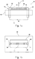
- Fig. 1A shows a side view, or elevation view of a cathode 10 for an X-ray tube.
- the cathode 10 comprises a filament 12, a support structure 14, a body structure 16, and a filament frame structure 18.
- the support structure 14 comprises a first mounting bolt 20 and a second bolt 22.
- the filament 12 is provided to emit electrons towards an anode (not shown) in an electron emitting direction 24.
- the filament 12 at least partially comprises a helical structure 26.
- the filament 12 is held by the support structure 14, which is fixedly connected to the body structure 16.
- the filament frame structure 18 is provided for electron-optical focusing of the emitted electrons.
- the filament frame structure is provided adjacent to the outer boundaries of the filament 12, which is also shown in Fig. 1B showing the cathode 10 of Fig. 1A in a top view.
- the filament frame structure 18 comprises frame surface portions 28 and 30 arranged transverse to the emitting direction 24.
- the filament frame structure 18 is held by the support structure 14.
- a connection 32 of the support structure 14 to an electrical source 34 is schematically indicated.
- the mounting bolts extending through the body structure 16 can have a respective connection at the side opposite to the side where the filament 12 is arranged.
- the electrical source provides the electrical potential to the filament 12 (not further shown).
- the filament 12 is a straight end helical filament 32, wherein the connecting ends 34 of the winding are aligned to a longitudinal direction around which the helical winding of the filament 12 is provided.
- Fig. 1A and 1B show the filament as a straight end helical filament
- the filament of Fig. 1A and 1B may also be provided with differently arranged ends, i.e. in another form as a straight end helical filament as shown. This is also the case for the further figures.
- the filament frame structure 18 comprises, according to the present invention, at least one positioning device 36 for at least one positioning direction 38, indicated in Fig. 2B with a double arrow, of the filament 12 in relation with the body structure 16.
- a small leash is provided at the inner side of one of the surface portions, for example the portion 28, thus providing an abutting or stopping piece of the frame portion in order to properly position the filament 12.
- the protruding leash can be removed or bent away once the filament 12 is fixedly connected to the support structure 14.
- a second positioning device 40 for a second positioning direction 42, indicated in Fig. 3 with a double arrow, of the filament 12 in relation with the body structure 16 can be provided.
- a segment is provided at an inner side of one of the surface portions, for example portion 28, providing a longitudinal abutting surface for the proper alignment of the filament 12.
- the second positioning device may be removed, i.e. cut away or bent, away after the fixation of the filament 12 to the support structure 14.
- positioning means i.e. other forms of abutting surfaces in one of the described directions can be provided, or also in a further direction, for example perpendicular to the second direction 42 and perpendicular to the longitudinal direction of the filament 12, for providing respective abutting or resting surfaces for the alignment of the filament 12.
- the positioning device provides a mechanical stop for abutting the filament's coil wounding in at least one direction, for example the linear direction of the filament.
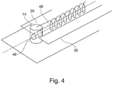
- fitting members 46 for receiving parts of a filament support arrangement are provided at the support structure 14.
- the fitting members 46 are provided as through-holes through the mounting bolt 20, or 22, such that a straight filament mounting-pin 50 (shown in Fig. 6 et seq.), can be provided for the assembly and later removed.
- the respective fitting members for receiving parts of a filament support arrangement are provided at the filament frame support alternatively or in addition to the fitting members for receiving parts of a filament support arrangement at the support structure.
- the support structure 14 comprises a reception 52, as also shown in Fig. 5A and 5B , for receiving two ends of the straight filament mounting-pin 50, which is provided during the mounting of the filament, and which pin is insertable within the filament's coil opening for correct placing of the filament, and also for holding and supporting the filament 12.
- Fig. 5A shows the mounting bolt 20 with the through-hole of the reception 52 and the filament 12. Further, a dotted line 54 indicates the longitudinal direction of the filament 12. Still further, the filament frame structure 18 is only indicated.
- a first resting protrusion 56 is provided, which is also shown in Fig. 5B showing a view perpendicular to the view of Fig. 5A , viewing towards the mounting bolt 20.
- the protrusion 56 is provided with an adapted inner rounded surface 58, such that it is conforming to the through-hole of the reception 52.
- the filament frame structure 18 may be provided with a reception 60 for receiving the mounting-pin 50.
- the mounting-pin 50 for supporting the filament 12, and to rest the mounting-pin 50 on the frame structure.
- the filament frame structure 18 acts as a mounting tool. The mounting-pin 50 together with the filament 12 and the filament frame structure 18 can thus be positioned together such that the filament 12 is properly aligned.
- the receiving reception 60 of the filament frame structure 18 can be provided by a bended portion 62, as shown in Fig. 5D . Further, it is also possible to remove the respective portion of the frame structure once the frame structure 18 is connected to the support structure 14 and the mounting-pin 50 is removed. For example, the small leashes connecting the bended portion 62 to the other portions of the filament frame structure can be cut away, as indicated with dotted lines 64.
- the pin may also be provided with a different shape resulting in, for example, a curved filament, instead of a straight and linear element for the pin.
- the frame surface portions and the filament centre line may be arranged in a common layer.
- the support structure 14 comprises support pins, for example the mounting bolt, brazed to the body structure.
- the support pins for example the mounting bolts, may be machined accurately by electron discharge machining (EDM) after being brazed.
- EDM electron discharge machining
- the support structure may be made integrally with a body structure, wherein the filament frame structure is brazed to the body structure representing the support structure.
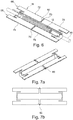
- Fig. 6 shows the filament frame structure 18 together with the mounting-pin 50 and the filament 12.
- the filament frame structure 18 comprises two longitudinal frame surface portions 66 and 68 on either side of the filament 12.
- a small gap 70 is provided, thus separating the respective frame surface portions into two sub-portions, resulting in a first sub-portion 72 and a second sub-portion 74 for the side 66, and a third sub-portion 76 and a forth sub-portion 78 for the opposite side 68.
- Fig. 6 shows the bars in a middle portion
- the bars 80 can also be provided on the side portion, as shown in Fig. 7A in a perspective view showing the frame only, and the respective top view in Fig. 7B .
- Fig. 6 and also Figs. 7ff., show the filament frame structure 18 with end portions bended outwardly, for example to rest on the outer sides of the mounting bolts 20, 22, whereas Fig. 5D shows an inwardly bended portion for providing a respective support reception for the mounting-pin 50.
- the prevision of the gaps 70 and the bars 80 may also be provided for the inwardly bended version of Fig. 5D .
- Fig. 6 shows the mounting-pin 50 holding the filament 12 for the handling procedure.
- Fig. 8 shows a perspective view of the filament aligned with the support structure 14.
- the mounting bolts are provided with a longitudinal groove for facilitating the proper positioning of the filament 12.
- Fig. 8 shows the body structure 16 as a cathode with a surface profile
- Fig. 9 shows the body structure 16 with a flat surface in the area of the filament 12 and the filament frame structure 18.
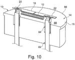
- Fig. 10 shows a cross-section of a further example.
- the filament 12 is connected to the mounting bolts 20, 22 of the support structure 14 and the filament frame structure 18 is also connected and thus held by the support structure 14.
- the mounting bolts of the support structure 14 are extending through the body structure 16. Therefore, a stepped through-hole 82 is provided with an upper portion 84 having a larger diameter as the lower portion.
- the brazing e.g. high temperature soldering
- the connecting of the filament 12 and the connecting of the filament frame structure 18 to the same support structure 14 allows an independent movement during the operation, for example due to a thermal expansion.
- a proper alignment in respect of the electron-optical focusing is provided throughout the operation.
- the cathode 10 is provided with a cathode cup 86 as having a flat front side 88, wherein the filament 12 is arranged on the flat front side 88, as shown in Fig. 10 as an example.
- the feature of the cathode cup having a flat front side may in particular be combined with the features shown in Figs. 1 to 9 .
- the filament 12 is totally recrystallized, inside to achieve required straightness.
- the filament 12 is made of W or high temperature ceramics such as BN and the like.
- the pin may be provided inserted into the helical structure during the recrystallization.
- the guiding pin 80 may also have a groove to fix the straight ends of the filament in a plane while the recrystallization process is conducted.
- radiation cooling at temperatures with high infrared radiation is provided by the flat surface portions of the filament frame structure, but below thermionic emission level.
- the filament frame structure can be attached in one piece and, for example, laser-cut after assembly, in order to separate electrical potentials.
- one piece or multi-piece frames are possible.
- the isolation of the frame or counter parts may also be facilitated.
- the filament frame structure may be provided on a mounting support for the frame structure parts, thus a laser cutting process is not necessary after the assembly. However, an additional tool would be necessary for the mounting of the frame parts.
- the filament is provided with a pretension in a non-operating state, for example provided by the support structure 14.
- the pretension can be provided by the filament frame structure being a one piece component.
- the pretension while mounting is provided, for example to compensate thermal expansion of the filament, e.g. the coil, due to heating during operation.
- the pretension is adjusted to minimize mechanical stresses in operation, reducing plastic deformation and distortion of the filament 12.
- thermal mechanical and electron-optic stability is improved.
- the pretension can be applied by the filament frame structure, or also by an additional tool.
- the pretension may also be applied by a controlled deformation of the support bars 80, after the filament welding, the curved bars are to be compressed by a tool, resulting in longitudinal stretching of frames.
- the bars are then, as mentioned above, laser-cut after assembly, to separate electrical potentials.
- the body structure 16 is provided as a cathode cup, for example the cathode cup 86.
- the cathode cup is provided as a ceramic cathode cup, made from electrically non-conducting ceramic. A part of the cathode cup's surfaces is provided with a metallic coating.
- the metallization is provided on the surfaces for brazing and electrical purposes, e.g. to avoid surface charges.
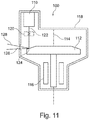
- Fig. 11 shows an X-ray tube 100 comprising a cathode 110, and an anode 112.
- the cathode is provided as a cathode according to one of the above mentioned and described examples.
- the X-ray tube is provided with a rotating anode, indicated with a rotation axis 114.
- driving device 116 are indicated, whereas only the parts inside a tube housing 118 are shown, neglecting any parts being outside, for example a scatter of the driving means.
- steering or deflection means device 120 is shown for deflecting an electron beam 122 from the cathode 110 towards a focal spot portion 124 on the anode 112.
- An X-ray transparent window 126 is shown such that an X-ray beam 128 is radiated towards a not further shown object.
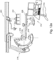
- Fig. 12A is a schematic drawing of an X-ray tube.
- a system 200 for X-ray imaging comprising an X-ray source 210, and X-ray detector 212, and a processing unit 214.
- the processing unit 214 is configured to control the X-ray source 210 and the X-ray detector 212 for providing X-ray image data of an object of interest 216.
- the X-ray source 210 is provided as an X-ray tube 100 according to the above mentioned example.
- the X-ray system may be a medical imaging system as shown in Fig. 12A .
- the X-ray source 210 and the X-ray detector 212 are provided as a so-called C-arm arrangement 218, where a C-arm structure is movably mounted to a support arrangement in order to provide free arrangement of the source and detector around the object of interest.
- a patient table as well as monitoring devices 222 and lighting devices 224 are shown indicating an operational room in a hospital, for example.
- an inspection apparatus 226 is provided, for example for scanning and screening of luggage pieces 228, or for material and construction inspection.
- This is shown in Fig. 12B as a further example for an X-ray system 200 for X-ray imaging, comprising an X-ray source which is provided as an X-ray tube according to the above mentioned examples. It is noted that the X-ray source is not further shown in Fig. 12B .
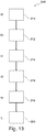
- Fig. 13 shows a method 300 for an assembly of a cathode for an X-ray tube, comprising the following steps.
- a filament is provided, wherein the filament is configured to emit electrons towards an anode in an electron emitting direction, and wherein the filament at least partially comprises a helical structure.
- the filament is aligned with respect to a filament frame structure, wherein the filament frame structure is configured for electron-optical focusing of the emitted electrons, wherein the filament frame structure is provided adjacent to the outer boundaries of the filament, and wherein the filament frame structure comprises frame surface portions arranged transverse to the emitting direction.
- the filament is connected to the filament frame structure.
- a support structure is connected to a body structure.
- the filament frame structure is placed on the support structure.
- a sixth step 320 the filament frame structure and the filament are connected to the support structure.
- the first step 310 is also referred to as step a), the second step 312 as step b), the third step 314 as step c), the fourth step 316 as step d), the fifth step 318 as step e), and the sixth step 320 as step f).
- the filament frame structure may be connected to the body structure, in addition or instead of being connected to the support structure, for example in case of a ceramic cathode head.
- the filament frame structure is provided such that a movement in combination with the filament is provided in case of thermal expansion.
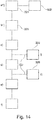
- a support guide is provided in a first preparation step 322 for the assembly.
- the steps are provided as step a1) in which the filament is provided 324 on the support guide.
- the support guide is aligned 326 with respect to the filament frame structure.
- the support guide is then removed in a further step 328, for example as a step i) after the filament is connected to the filament frame structure, or as step ii) after the filament frame structure is connected to the support structure. This is indicated by dotted lines 330 in Fig. 14 indicating the two possibilities as alternative options.
- a total recrystallizing of the filament is provided by applying external heat.
- the recrystallizing may be provided, for example, before step c).
Landscapes
- Engineering & Computer Science (AREA)
- Manufacturing & Machinery (AREA)
- Chemical & Material Sciences (AREA)
- Analytical Chemistry (AREA)
- X-Ray Techniques (AREA)
- Electron Sources, Ion Sources (AREA)
- Physics & Mathematics (AREA)
- Health & Medical Sciences (AREA)
- Life Sciences & Earth Sciences (AREA)
- Biochemistry (AREA)
- General Health & Medical Sciences (AREA)
- General Physics & Mathematics (AREA)
- Immunology (AREA)
- Pathology (AREA)
Claims (14)
- Kathode (10) für eine Röntgenröhre, umfassend:- ein Filament (12);- eine Halterungsstruktur (14);- eine Körperstruktur (16); und- eine Filamentrahmenstruktur (18);wobei das Filament vorgesehen ist, um Elektronen in eine Elektronenemissionsrichtung (24) auf eine Anode zu zu emittieren; und wobei das Filament mindestens teilweise eine spiralförmige Struktur (26) umfasst;
wobei das Filament durch die Halterungsstruktur gehalten wird, die fest mit der Körperstruktur verbunden ist;
wobei die Filamentrahmenstruktur für das elektronenoptische Fokussieren der emittierten Elektronen vorgesehen ist; wobei die Filamentrahmenstruktur angrenzend an die Außengrenzen des Filaments vorgesehen ist; wobei die Filamentrahmenstruktur Rahmenoberflächenabschnitte (28) umfasst, die quer zu der Emissionsrichtung angeordnet sind;
wobei die Filamentrahmenstruktur durch die Halterungsstruktur gehalten wird; und
dadurch gekennzeichnet, dass die Filamentrahmenstruktur mindestens eine Positioniervorrichtung (36) für mindestens eine Positionierungsrichtung (38) des Filaments in Bezug auf die Körperstruktur umfasst. - Kathode nach Anspruch 1, wobei das Filament ein spiralförmiges Filament (32) mit geradem Ende ist;
wobei die Anschlussenden der Windung auf eine Längsrichtung ausgerichtet sind, um die die spiralförmige Windung des Filaments vorgesehen ist. - Kathode nach Anspruch 1 oder 2, wobei die Filamentrahmenstruktur mindestens eine zweite Positioniervorrichtung (40) für eine zweite Positionierungsrichtung (42) des Filaments in Bezug auf die Körperstruktur umfasst.
- Kathode nach einem der vorhergehenden Ansprüche, wobei Befestigungselemente (46) zum Aufnehmen von Teilen einer Filamenthalterungsanordnung (48) an der Halterungsstruktur und/oder an der Filamentrahmenstruktur (18) vorgesehen sind;
wobei die Filamenthalterungsanordnung ein gerader Filamentmontagestift (50) ist, der während der Montage des Filaments vorgesehen wird, und der in die Spulenöffnung des Filaments eingeführt werden kann, um für eine korrekte Platzierung des Filaments zu sorgen. - Kathode nach Anspruch 4, wobei die Halterungsstruktur eine Aufnahme zum Aufnehmen von zwei Enden des geraden Filamentmontagestifts (50) umfasst.
- Kathode nach Anspruch 4, wobei die Filamentrahmenstruktur als die Befestigungselemente eine Aufnahme (60) zum Aufnehmen der beiden Enden des geraden Filamentmontagestifts umfasst, der während der Montage des Filaments vorgesehen wird und der in die Spulenöffnung des Filaments eingeführt werden kann, um für eine korrekte Platzierung des Filaments zu sorgen.
- Kathode nach einem der vorhergehenden Ansprüche, wobei das Filament in einem Nicht-Betriebszustand mit einer durch die Halterungsstruktur bereitgestellten Vorspannung angeordnet ist.
- Kathode nach einem der vorhergehenden Ansprüche, wobei die Körperstruktur als ein Kathodenbecher (48) vorgesehen ist;
wobei der Kathodenbecher als ein keramischer Kathodenbecher bestehend aus elektrisch nicht leitfähiger Keramik vorgesehen ist; und
wobei ein Teil der Oberflächen des Kathodenbechers mit einer metallischen Beschichtung versehen ist. - Kathode nach Anspruch 8, wobei der Kathodenbecher mit einer flachen Vorderseite (88) vorgesehen ist und wobei das Filament auf der flachen Vorderseite angeordnet ist.
- Röntgenröhre (100), umfassend- eine Kathode (110);- eine Anode (112);wobei die Kathode als eine Kathode nach einem der vorhergehenden Ansprüche vorgesehen ist.
- System (200) zur Röntgenbildgebung, umfassend:- eine Röntgenquelle (210);- einen Röntgendetektor (212); und- eine Verarbeitungseinheit (214);wobei die Verarbeitungseinheit konfiguriert ist, um die Röntgenquelle und den Röntgendetektor zur Bereitstellung von Röntgenbilddaten eines interessierenden Objekts zu steuern; und
wobei die Röntgenquelle als eine Röntgenquelle nach Anspruch 9 vorgesehen ist. - Verfahren (300) zur Montage einer Kathode einer Röntgenröhre, wobei das Verfahren die folgenden Schritte umfasst:a) Bereitstellen (310) eines Filaments;
wobei das Filament konfiguriert ist, um Elektronen in eine Elektronenemissionsrichtung auf eine Anode zu zu emittieren; und wobei das Filament mindestens teilweise eine spiralförmige Struktur umfasst;b) Ausrichten (312) des Filaments in Bezug auf eine Filamentrahmenstruktur;
wobei die Filamentrahmenstruktur für das elektronenoptische Fokussieren der emittierten Elektronen konfiguriert ist; wobei die Filamentrahmenstruktur angrenzend an die Außengrenzen des Filaments vorgesehen ist; wobei die Filamentrahmenstruktur Rahmenoberflächenabschnitte umfasst, die quer zu der Emissionsrichtung angeordnet sind; und wobei die Filamentrahmenstruktur mindestens eine Positioniervorrichtung (36) für mindestens eine Positionierungsrichtung (38) des Filaments in Bezug auf die Körperstruktur umfasst;c) Verbinden (314) des Filaments mit der Filamentrahmenstruktur;d) Verbinden (316) einer Halterungsstruktur mit einer Körperstruktur;e) Platzieren (318) der Filamentrahmenstruktur auf der Halterungsstruktur; undf) Befestigen (320) der Filamentrahmenstruktur und des Filaments an der Halterungsstruktur. - Verfahren nach Anspruch 12, wobei eine Halterungsführung für die Baugruppe vorgesehen (322) ist, und die Schritte vorgesehen sind als:a1) Bereitstellen (324) des Filaments an der Halterungsführung;b1) Ausrichten (326) der Halterungsführung in Bezug auf die Filamentrahmenstruktur;wobei die Halterungsführung entfernt (328) wird,i) nachdem das Filament mit der Filamentrahmenstruktur verbunden ist, oderii) nachdem die Filamentrahmenstruktur an der Halterungsstruktur befestigt ist.
- Verfahren nach Anspruch 12 oder 13, wobei im Anschluss an Schritt a), aber vor dem Platzieren aus Schritt e), eine Gesamtrekristallisierung des Filaments durch Anwenden von äußerer Wärme vorgesehen ist.
Applications Claiming Priority (2)
| Application Number | Priority Date | Filing Date | Title |
|---|---|---|---|
| US201261649973P | 2012-05-22 | 2012-05-22 | |
| PCT/IB2013/054181 WO2013175402A1 (en) | 2012-05-22 | 2013-05-21 | Cathode filament assembly |
Publications (2)
| Publication Number | Publication Date |
|---|---|
| EP2852964A1 EP2852964A1 (de) | 2015-04-01 |
| EP2852964B1 true EP2852964B1 (de) | 2017-02-08 |
Family
ID=48747637
Family Applications (1)
| Application Number | Title | Priority Date | Filing Date |
|---|---|---|---|
| EP13734502.1A Active EP2852964B1 (de) | 2012-05-22 | 2013-05-21 | Kathodenfilamentanordnung |
Country Status (7)
| Country | Link |
|---|---|
| US (1) | US9916959B2 (de) |
| EP (1) | EP2852964B1 (de) |
| JP (1) | JP6392746B2 (de) |
| CN (1) | CN104488063B (de) |
| BR (1) | BR112014028913A2 (de) |
| RU (1) | RU2014151770A (de) |
| WO (1) | WO2013175402A1 (de) |
Families Citing this family (13)
| Publication number | Priority date | Publication date | Assignee | Title |
|---|---|---|---|---|
| CN103794431B (zh) * | 2014-01-17 | 2016-04-13 | 杭州凯龙医疗器械有限公司 | 一种x射线管灯丝定型装置及其定型方法 |
| JP7092664B2 (ja) * | 2015-11-13 | 2022-06-28 | コーニンクレッカ フィリップス エヌ ヴェ | X線管用カソード |
| CN106531592B (zh) | 2016-12-29 | 2018-12-28 | 清华大学 | 电子枪以及具有该电子枪的x射线光源与ct设备 |
| JP7197245B2 (ja) * | 2017-01-12 | 2022-12-27 | キヤノン電子管デバイス株式会社 | X線管及びx線管の製造方法 |
| US10636608B2 (en) * | 2017-06-05 | 2020-04-28 | General Electric Company | Flat emitters with stress compensation features |
| KR102138020B1 (ko) * | 2018-09-17 | 2020-07-27 | (주)선재하이테크 | 연엑스선 튜브 |
| US10910187B2 (en) * | 2018-09-25 | 2021-02-02 | General Electric Company | X-ray tube cathode flat emitter support mounting structure and method |
| CN109300755B (zh) * | 2018-10-19 | 2024-09-10 | 散裂中子源科学中心 | 一种x射线管、辐照腔、x射线源设备及应用 |
| WO2022021942A1 (en) | 2020-07-27 | 2022-02-03 | Shanghai United Imaging Healthcare Co., Ltd. | Radiotherapy device and microwave source thereof |
| CN111729212A (zh) * | 2020-07-27 | 2020-10-02 | 上海联影医疗科技有限公司 | 微波源的阴极加热器、阴极和放射治疗设备 |
| JP7431649B2 (ja) * | 2020-04-13 | 2024-02-15 | 浜松ホトニクス株式会社 | 電子線発生源、電子線照射装置、及びx線照射装置 |
| KR102780440B1 (ko) * | 2021-12-22 | 2025-03-14 | 주식회사 쎄크 | 필라멘트 조정 구조를 포함하는 엑스레이 튜브 |
| CN219735142U (zh) * | 2023-01-19 | 2023-09-22 | 杭州杭科光电集团股份有限公司 | 一种灯管、灯具及灯体 |
Family Cites Families (39)
| Publication number | Priority date | Publication date | Assignee | Title |
|---|---|---|---|---|
| US2019600A (en) * | 1932-07-14 | 1935-11-05 | Westinghouse Lamp Co | Line focus cathode structure |
| BE437941A (de) * | 1939-02-17 | 1900-01-01 | ||
| US2290226A (en) * | 1940-12-19 | 1942-07-21 | Mond Jesse W M Du | X-ray generating device |
| US2585702A (en) * | 1945-06-12 | 1952-02-12 | Atomic Energy Commission | Spectrometer |
| US2671867A (en) * | 1950-11-24 | 1954-03-09 | Dunlee Corp | Electrode structure for x-ray tubes |
| US2909701A (en) * | 1955-07-06 | 1959-10-20 | Westinghouse Electric Corp | Cathode heater system for electron discharge device |
| US2885582A (en) * | 1956-04-03 | 1959-05-05 | Gen Electric | X-ray tube |
| US3631289A (en) * | 1969-05-23 | 1971-12-28 | Picker Corp | X-ray filament with balanced emission |
| JPS5339738B1 (de) * | 1970-12-29 | 1978-10-23 | ||
| US3783323A (en) * | 1972-08-30 | 1974-01-01 | Picker Corp | X-ray tube having focusing cup with non-emitting coating |
| US3875028A (en) * | 1972-08-30 | 1975-04-01 | Picker Corp | Method of manufacture of x-ray tube having focusing cup with non emitting coating |
| US3943393A (en) * | 1975-02-13 | 1976-03-09 | The Machlett Laboratories, Inc. | Stress free filament structure |
| JPS52116156U (de) * | 1976-03-01 | 1977-09-03 | ||
| JPS5568056A (en) * | 1978-11-17 | 1980-05-22 | Hitachi Ltd | X-ray tube |
| US4307318A (en) * | 1980-02-14 | 1981-12-22 | Westinghouse Electric Corp. | Miniature lamp and method |
| JPS58106858U (ja) | 1982-01-13 | 1983-07-20 | 株式会社東芝 | X線管の陰極構体 |
| JPS58123643A (ja) * | 1982-01-19 | 1983-07-22 | Toshiba Corp | X線管用陰極及びその製造方法 |
| JPH02128355U (de) * | 1989-03-30 | 1990-10-23 | ||
| DE4021709A1 (de) | 1990-07-07 | 1992-01-09 | Philips Patentverwaltung | Elektronenroehre mit einer kathodenanordnung, die eine heizdrahtwendel umfasst |
| US5438605A (en) | 1992-01-06 | 1995-08-01 | Picker International, Inc. | Ring tube x-ray source with active vacuum pumping |
| DE4325609A1 (de) * | 1993-07-30 | 1995-02-02 | Philips Patentverwaltung | Elektronenröhre |
| JP3076711B2 (ja) * | 1993-08-17 | 2000-08-14 | 松下電子工業株式会社 | 始動器内蔵形高圧ナトリウムランプ |
| US5515413A (en) | 1994-09-26 | 1996-05-07 | General Electric Company | X-ray tube cathode cup assembly |
| US6066019A (en) | 1998-12-07 | 2000-05-23 | General Electric Company | Recrystallized cathode filament and recrystallization method |
| JP2001084933A (ja) | 1999-09-10 | 2001-03-30 | Toshiba Corp | X線管用陰極構体およびその製造方法 |
| US6419758B1 (en) * | 1999-09-10 | 2002-07-16 | General Electric Company | Cathode wire filament for x-ray tube applications |
| US6607416B2 (en) * | 2001-06-08 | 2003-08-19 | Koninklijke Philips Electronics N.V. | Method and apparatus for setting X-ray tube filaments |
| US6762540B2 (en) | 2002-10-25 | 2004-07-13 | Ge Medical Systems Global Technology Company, Llc | One-piece tab assembly for a cathode cup of an X-ray imaging machine |
| US6952466B2 (en) * | 2002-11-12 | 2005-10-04 | Ge Medical Systems Global Technology Company, Llc | Oil-free electron source for an EBT scanner |
| US6987835B2 (en) | 2003-03-26 | 2006-01-17 | Xoft Microtube, Inc. | Miniature x-ray tube with micro cathode |
| US7130380B2 (en) * | 2004-03-13 | 2006-10-31 | Xoft, Inc. | Extractor cup on a miniature x-ray tube |
| JP2006331853A (ja) | 2005-05-26 | 2006-12-07 | Jeol Ltd | フィラメントアセンブリ及び電子銃並びに電子ビーム装置 |
| WO2007000971A1 (ja) | 2005-06-27 | 2007-01-04 | Hitachi Medical Corporation | X線管及びx線管装置とx線管の製造方法 |
| JP4781156B2 (ja) | 2006-04-18 | 2011-09-28 | 株式会社日立メディコ | 透過型x線管 |
| EP2156459B1 (de) | 2007-06-01 | 2013-03-27 | Philips Intellectual Property & Standards GmbH | Verfahren zu ihrer herstellung einer elektronenemissionsfolie mit leisten zur vorübergehenden fixierung |
| US7668296B2 (en) | 2007-06-14 | 2010-02-23 | General Electric Co. | X ray tube assembly and method of manufacturing and using the X ray tube assembly |
| WO2009013677A1 (en) | 2007-07-24 | 2009-01-29 | Philips Intellectual Property & Standards Gmbh | Thermionic electron emitter and x-ray source including same |
| WO2009013685A1 (en) | 2007-07-24 | 2009-01-29 | Philips Intellectual Property & Standards Gmbh | Thermionic electron emitter, method for preparing same and x-ray source including same |
| DE102011004372A1 (de) * | 2011-02-18 | 2011-11-17 | Siemens Aktiengesellschaft | Kathode |
-
2013
- 2013-05-21 JP JP2015513332A patent/JP6392746B2/ja not_active Expired - Fee Related
- 2013-05-21 WO PCT/IB2013/054181 patent/WO2013175402A1/en not_active Ceased
- 2013-05-21 EP EP13734502.1A patent/EP2852964B1/de active Active
- 2013-05-21 US US14/397,557 patent/US9916959B2/en active Active
- 2013-05-21 CN CN201380026685.0A patent/CN104488063B/zh active Active
- 2013-05-21 RU RU2014151770A patent/RU2014151770A/ru not_active Application Discontinuation
- 2013-05-21 BR BR112014028913A patent/BR112014028913A2/pt not_active IP Right Cessation
Non-Patent Citations (1)
| Title |
|---|
| None * |
Also Published As
| Publication number | Publication date |
|---|---|
| RU2014151770A (ru) | 2016-07-20 |
| US9916959B2 (en) | 2018-03-13 |
| US20150124931A1 (en) | 2015-05-07 |
| CN104488063B (zh) | 2017-06-09 |
| EP2852964A1 (de) | 2015-04-01 |
| CN104488063A (zh) | 2015-04-01 |
| WO2013175402A1 (en) | 2013-11-28 |
| JP6392746B2 (ja) | 2018-09-19 |
| BR112014028913A2 (pt) | 2017-06-27 |
| JP2015524144A (ja) | 2015-08-20 |
Similar Documents
| Publication | Publication Date | Title |
|---|---|---|
| EP2852964B1 (de) | Kathodenfilamentanordnung | |
| EP3375005B1 (de) | Verfahren zum zusammenbau einer kathode für eine röntgenröhre | |
| EP2768010A2 (de) | Strahlungsröhre und Strahlungsabbildungssystem mit der Röhre | |
| US11990309B2 (en) | Biased cathode assembly of an x-ray tube with improved thermal management and a method of manufacturing same | |
| US9711321B2 (en) | Low aberration, high intensity electron beam for X-ray tubes | |
| US6801599B1 (en) | X-ray tube cathode cup structure for focal spot deflection | |
| US10497533B2 (en) | X-ray generating tube including electron gun, X-ray generating apparatus and radiography system | |
| CN110854002B (zh) | 用于发射器附接系统和方法的阴极发射器 | |
| CN110942966B (zh) | X射线管阴极平坦发射器支撑安装结构和方法 | |
| US7828621B2 (en) | Apparatus and methods for producing multi-electrode cathode for X-ray tube | |
| CN212934547U (zh) | 辐射阴极的限制装置、聚焦头、阴极单元和x射线设备 | |
| JP4597517B2 (ja) | 焦点偏向のためのx線陰極カップ構造 | |
| US12230413B2 (en) | Electron beam generator, electron beam emission device and X-ray emission device | |
| JP2022073156A (ja) | エネルギー線管 | |
| JPH04248233A (ja) | X線管の陰極構体 |
Legal Events
| Date | Code | Title | Description |
|---|---|---|---|
| PUAI | Public reference made under article 153(3) epc to a published international application that has entered the european phase |
Free format text: ORIGINAL CODE: 0009012 |
|
| 17P | Request for examination filed |
Effective date: 20141222 |
|
| AK | Designated contracting states |
Kind code of ref document: A1 Designated state(s): AL AT BE BG CH CY CZ DE DK EE ES FI FR GB GR HR HU IE IS IT LI LT LU LV MC MK MT NL NO PL PT RO RS SE SI SK SM TR |
|
| AX | Request for extension of the european patent |
Extension state: BA ME |
|
| DAX | Request for extension of the european patent (deleted) | ||
| GRAP | Despatch of communication of intention to grant a patent |
Free format text: ORIGINAL CODE: EPIDOSNIGR1 |
|
| INTG | Intention to grant announced |
Effective date: 20160822 |
|
| GRAS | Grant fee paid |
Free format text: ORIGINAL CODE: EPIDOSNIGR3 |
|
| GRAA | (expected) grant |
Free format text: ORIGINAL CODE: 0009210 |
|
| AK | Designated contracting states |
Kind code of ref document: B1 Designated state(s): AL AT BE BG CH CY CZ DE DK EE ES FI FR GB GR HR HU IE IS IT LI LT LU LV MC MK MT NL NO PL PT RO RS SE SI SK SM TR |
|
| REG | Reference to a national code |
Ref country code: GB Ref legal event code: FG4D |
|
| REG | Reference to a national code |
Ref country code: CH Ref legal event code: EP Ref country code: AT Ref legal event code: REF Ref document number: 867190 Country of ref document: AT Kind code of ref document: T Effective date: 20170215 |
|
| REG | Reference to a national code |
Ref country code: IE Ref legal event code: FG4D |
|
| REG | Reference to a national code |
Ref country code: DE Ref legal event code: R096 Ref document number: 602013017312 Country of ref document: DE |
|
| REG | Reference to a national code |
Ref country code: LT Ref legal event code: MG4D |
|
| REG | Reference to a national code |
Ref country code: NL Ref legal event code: MP Effective date: 20170208 |
|
| REG | Reference to a national code |
Ref country code: AT Ref legal event code: MK05 Ref document number: 867190 Country of ref document: AT Kind code of ref document: T Effective date: 20170208 |
|
| PG25 | Lapsed in a contracting state [announced via postgrant information from national office to epo] |
Ref country code: LT Free format text: LAPSE BECAUSE OF FAILURE TO SUBMIT A TRANSLATION OF THE DESCRIPTION OR TO PAY THE FEE WITHIN THE PRESCRIBED TIME-LIMIT Effective date: 20170208 Ref country code: NO Free format text: LAPSE BECAUSE OF FAILURE TO SUBMIT A TRANSLATION OF THE DESCRIPTION OR TO PAY THE FEE WITHIN THE PRESCRIBED TIME-LIMIT Effective date: 20170508 Ref country code: HR Free format text: LAPSE BECAUSE OF FAILURE TO SUBMIT A TRANSLATION OF THE DESCRIPTION OR TO PAY THE FEE WITHIN THE PRESCRIBED TIME-LIMIT Effective date: 20170208 Ref country code: GR Free format text: LAPSE BECAUSE OF FAILURE TO SUBMIT A TRANSLATION OF THE DESCRIPTION OR TO PAY THE FEE WITHIN THE PRESCRIBED TIME-LIMIT Effective date: 20170509 Ref country code: FI Free format text: LAPSE BECAUSE OF FAILURE TO SUBMIT A TRANSLATION OF THE DESCRIPTION OR TO PAY THE FEE WITHIN THE PRESCRIBED TIME-LIMIT Effective date: 20170208 |
|
| PG25 | Lapsed in a contracting state [announced via postgrant information from national office to epo] |
Ref country code: BG Free format text: LAPSE BECAUSE OF FAILURE TO SUBMIT A TRANSLATION OF THE DESCRIPTION OR TO PAY THE FEE WITHIN THE PRESCRIBED TIME-LIMIT Effective date: 20170508 Ref country code: LV Free format text: LAPSE BECAUSE OF FAILURE TO SUBMIT A TRANSLATION OF THE DESCRIPTION OR TO PAY THE FEE WITHIN THE PRESCRIBED TIME-LIMIT Effective date: 20170208 Ref country code: PT Free format text: LAPSE BECAUSE OF FAILURE TO SUBMIT A TRANSLATION OF THE DESCRIPTION OR TO PAY THE FEE WITHIN THE PRESCRIBED TIME-LIMIT Effective date: 20170608 Ref country code: RS Free format text: LAPSE BECAUSE OF FAILURE TO SUBMIT A TRANSLATION OF THE DESCRIPTION OR TO PAY THE FEE WITHIN THE PRESCRIBED TIME-LIMIT Effective date: 20170208 Ref country code: AT Free format text: LAPSE BECAUSE OF FAILURE TO SUBMIT A TRANSLATION OF THE DESCRIPTION OR TO PAY THE FEE WITHIN THE PRESCRIBED TIME-LIMIT Effective date: 20170208 Ref country code: SE Free format text: LAPSE BECAUSE OF FAILURE TO SUBMIT A TRANSLATION OF THE DESCRIPTION OR TO PAY THE FEE WITHIN THE PRESCRIBED TIME-LIMIT Effective date: 20170208 Ref country code: NL Free format text: LAPSE BECAUSE OF FAILURE TO SUBMIT A TRANSLATION OF THE DESCRIPTION OR TO PAY THE FEE WITHIN THE PRESCRIBED TIME-LIMIT Effective date: 20170208 Ref country code: ES Free format text: LAPSE BECAUSE OF FAILURE TO SUBMIT A TRANSLATION OF THE DESCRIPTION OR TO PAY THE FEE WITHIN THE PRESCRIBED TIME-LIMIT Effective date: 20170208 Ref country code: LU Free format text: LAPSE BECAUSE OF NON-PAYMENT OF DUE FEES Effective date: 20170531 |
|
| PG25 | Lapsed in a contracting state [announced via postgrant information from national office to epo] |
Ref country code: IT Free format text: LAPSE BECAUSE OF FAILURE TO SUBMIT A TRANSLATION OF THE DESCRIPTION OR TO PAY THE FEE WITHIN THE PRESCRIBED TIME-LIMIT Effective date: 20170208 Ref country code: CZ Free format text: LAPSE BECAUSE OF FAILURE TO SUBMIT A TRANSLATION OF THE DESCRIPTION OR TO PAY THE FEE WITHIN THE PRESCRIBED TIME-LIMIT Effective date: 20170208 Ref country code: RO Free format text: LAPSE BECAUSE OF FAILURE TO SUBMIT A TRANSLATION OF THE DESCRIPTION OR TO PAY THE FEE WITHIN THE PRESCRIBED TIME-LIMIT Effective date: 20170208 Ref country code: SK Free format text: LAPSE BECAUSE OF FAILURE TO SUBMIT A TRANSLATION OF THE DESCRIPTION OR TO PAY THE FEE WITHIN THE PRESCRIBED TIME-LIMIT Effective date: 20170208 Ref country code: EE Free format text: LAPSE BECAUSE OF FAILURE TO SUBMIT A TRANSLATION OF THE DESCRIPTION OR TO PAY THE FEE WITHIN THE PRESCRIBED TIME-LIMIT Effective date: 20170208 |
|
| REG | Reference to a national code |
Ref country code: DE Ref legal event code: R097 Ref document number: 602013017312 Country of ref document: DE |
|
| PG25 | Lapsed in a contracting state [announced via postgrant information from national office to epo] |
Ref country code: DK Free format text: LAPSE BECAUSE OF FAILURE TO SUBMIT A TRANSLATION OF THE DESCRIPTION OR TO PAY THE FEE WITHIN THE PRESCRIBED TIME-LIMIT Effective date: 20170208 Ref country code: PL Free format text: LAPSE BECAUSE OF FAILURE TO SUBMIT A TRANSLATION OF THE DESCRIPTION OR TO PAY THE FEE WITHIN THE PRESCRIBED TIME-LIMIT Effective date: 20170208 Ref country code: SM Free format text: LAPSE BECAUSE OF FAILURE TO SUBMIT A TRANSLATION OF THE DESCRIPTION OR TO PAY THE FEE WITHIN THE PRESCRIBED TIME-LIMIT Effective date: 20170208 |
|
| PLBE | No opposition filed within time limit |
Free format text: ORIGINAL CODE: 0009261 |
|
| STAA | Information on the status of an ep patent application or granted ep patent |
Free format text: STATUS: NO OPPOSITION FILED WITHIN TIME LIMIT |
|
| REG | Reference to a national code |
Ref country code: CH Ref legal event code: PL |
|
| 26N | No opposition filed |
Effective date: 20171109 |
|
| GBPC | Gb: european patent ceased through non-payment of renewal fee |
Effective date: 20170521 |
|
| PG25 | Lapsed in a contracting state [announced via postgrant information from national office to epo] |
Ref country code: MC Free format text: LAPSE BECAUSE OF FAILURE TO SUBMIT A TRANSLATION OF THE DESCRIPTION OR TO PAY THE FEE WITHIN THE PRESCRIBED TIME-LIMIT Effective date: 20170208 |
|
| REG | Reference to a national code |
Ref country code: IE Ref legal event code: MM4A |
|
| PG25 | Lapsed in a contracting state [announced via postgrant information from national office to epo] |
Ref country code: LI Free format text: LAPSE BECAUSE OF NON-PAYMENT OF DUE FEES Effective date: 20170531 Ref country code: SI Free format text: LAPSE BECAUSE OF FAILURE TO SUBMIT A TRANSLATION OF THE DESCRIPTION OR TO PAY THE FEE WITHIN THE PRESCRIBED TIME-LIMIT Effective date: 20170208 Ref country code: CH Free format text: LAPSE BECAUSE OF NON-PAYMENT OF DUE FEES Effective date: 20170531 |
|
| REG | Reference to a national code |
Ref country code: FR Ref legal event code: ST Effective date: 20180131 |
|
| PG25 | Lapsed in a contracting state [announced via postgrant information from national office to epo] |
Ref country code: LU Free format text: LAPSE BECAUSE OF NON-PAYMENT OF DUE FEES Effective date: 20170521 |
|
| REG | Reference to a national code |
Ref country code: BE Ref legal event code: MM Effective date: 20170531 |
|
| PG25 | Lapsed in a contracting state [announced via postgrant information from national office to epo] |
Ref country code: IE Free format text: LAPSE BECAUSE OF NON-PAYMENT OF DUE FEES Effective date: 20170521 Ref country code: GB Free format text: LAPSE BECAUSE OF NON-PAYMENT OF DUE FEES Effective date: 20170521 |
|
| PG25 | Lapsed in a contracting state [announced via postgrant information from national office to epo] |
Ref country code: FR Free format text: LAPSE BECAUSE OF NON-PAYMENT OF DUE FEES Effective date: 20170531 |
|
| PG25 | Lapsed in a contracting state [announced via postgrant information from national office to epo] |
Ref country code: BE Free format text: LAPSE BECAUSE OF NON-PAYMENT OF DUE FEES Effective date: 20170531 |
|
| PG25 | Lapsed in a contracting state [announced via postgrant information from national office to epo] |
Ref country code: MT Free format text: LAPSE BECAUSE OF NON-PAYMENT OF DUE FEES Effective date: 20170521 |
|
| PG25 | Lapsed in a contracting state [announced via postgrant information from national office to epo] |
Ref country code: HU Free format text: LAPSE BECAUSE OF FAILURE TO SUBMIT A TRANSLATION OF THE DESCRIPTION OR TO PAY THE FEE WITHIN THE PRESCRIBED TIME-LIMIT; INVALID AB INITIO Effective date: 20130521 |
|
| PG25 | Lapsed in a contracting state [announced via postgrant information from national office to epo] |
Ref country code: CY Free format text: LAPSE BECAUSE OF FAILURE TO SUBMIT A TRANSLATION OF THE DESCRIPTION OR TO PAY THE FEE WITHIN THE PRESCRIBED TIME-LIMIT Effective date: 20170208 |
|
| PG25 | Lapsed in a contracting state [announced via postgrant information from national office to epo] |
Ref country code: MK Free format text: LAPSE BECAUSE OF FAILURE TO SUBMIT A TRANSLATION OF THE DESCRIPTION OR TO PAY THE FEE WITHIN THE PRESCRIBED TIME-LIMIT Effective date: 20170208 |
|
| PG25 | Lapsed in a contracting state [announced via postgrant information from national office to epo] |
Ref country code: TR Free format text: LAPSE BECAUSE OF FAILURE TO SUBMIT A TRANSLATION OF THE DESCRIPTION OR TO PAY THE FEE WITHIN THE PRESCRIBED TIME-LIMIT Effective date: 20170208 |
|
| PG25 | Lapsed in a contracting state [announced via postgrant information from national office to epo] |
Ref country code: AL Free format text: LAPSE BECAUSE OF FAILURE TO SUBMIT A TRANSLATION OF THE DESCRIPTION OR TO PAY THE FEE WITHIN THE PRESCRIBED TIME-LIMIT Effective date: 20170208 Ref country code: IS Free format text: LAPSE BECAUSE OF FAILURE TO SUBMIT A TRANSLATION OF THE DESCRIPTION OR TO PAY THE FEE WITHIN THE PRESCRIBED TIME-LIMIT Effective date: 20170608 |
|
| REG | Reference to a national code |
Ref country code: DE Ref legal event code: R082 Ref document number: 602013017312 Country of ref document: DE Representative=s name: MEISSNER BOLTE PATENTANWAELTE RECHTSANWAELTE P, DE Ref country code: DE Ref legal event code: R081 Ref document number: 602013017312 Country of ref document: DE Owner name: PHILIPS GMBH, DE Free format text: FORMER OWNER: PHILIPS GMBH, 20099 HAMBURG, DE |
|
| REG | Reference to a national code |
Ref country code: DE Ref legal event code: R084 Ref document number: 602013017312 Country of ref document: DE |
|
| PGFP | Annual fee paid to national office [announced via postgrant information from national office to epo] |
Ref country code: DE Payment date: 20250528 Year of fee payment: 13 |