EP2852491B1 - Colour 3-dimensional printing with 3d gamut mapping - Google Patents
Colour 3-dimensional printing with 3d gamut mapping Download PDFInfo
- Publication number
- EP2852491B1 EP2852491B1 EP13725284.7A EP13725284A EP2852491B1 EP 2852491 B1 EP2852491 B1 EP 2852491B1 EP 13725284 A EP13725284 A EP 13725284A EP 2852491 B1 EP2852491 B1 EP 2852491B1
- Authority
- EP
- European Patent Office
- Prior art keywords
- colour
- media
- layers
- printing
- layer
- Prior art date
- Legal status (The legal status is an assumption and is not a legal conclusion. Google has not performed a legal analysis and makes no representation as to the accuracy of the status listed.)
- Not-in-force
Links
Images


Classifications
-
- B—PERFORMING OPERATIONS; TRANSPORTING
- B22—CASTING; POWDER METALLURGY
- B22F—WORKING METALLIC POWDER; MANUFACTURE OF ARTICLES FROM METALLIC POWDER; MAKING METALLIC POWDER; APPARATUS OR DEVICES SPECIALLY ADAPTED FOR METALLIC POWDER
- B22F10/00—Additive manufacturing of workpieces or articles from metallic powder
-
- B—PERFORMING OPERATIONS; TRANSPORTING
- B29—WORKING OF PLASTICS; WORKING OF SUBSTANCES IN A PLASTIC STATE IN GENERAL
- B29C—SHAPING OR JOINING OF PLASTICS; SHAPING OF MATERIAL IN A PLASTIC STATE, NOT OTHERWISE PROVIDED FOR; AFTER-TREATMENT OF THE SHAPED PRODUCTS, e.g. REPAIRING
- B29C64/00—Additive manufacturing, i.e. manufacturing of three-dimensional [3D] objects by additive deposition, additive agglomeration or additive layering, e.g. by 3D printing, stereolithography or selective laser sintering
- B29C64/30—Auxiliary operations or equipment
- B29C64/386—Data acquisition or data processing for additive manufacturing
-
- B—PERFORMING OPERATIONS; TRANSPORTING
- B29—WORKING OF PLASTICS; WORKING OF SUBSTANCES IN A PLASTIC STATE IN GENERAL
- B29C—SHAPING OR JOINING OF PLASTICS; SHAPING OF MATERIAL IN A PLASTIC STATE, NOT OTHERWISE PROVIDED FOR; AFTER-TREATMENT OF THE SHAPED PRODUCTS, e.g. REPAIRING
- B29C64/00—Additive manufacturing, i.e. manufacturing of three-dimensional [3D] objects by additive deposition, additive agglomeration or additive layering, e.g. by 3D printing, stereolithography or selective laser sintering
- B29C64/10—Processes of additive manufacturing
- B29C64/141—Processes of additive manufacturing using only solid materials
- B29C64/147—Processes of additive manufacturing using only solid materials using sheet material, e.g. laminated object manufacturing [LOM] or laminating sheet material precut to local cross sections of the 3D object
-
- B—PERFORMING OPERATIONS; TRANSPORTING
- B29—WORKING OF PLASTICS; WORKING OF SUBSTANCES IN A PLASTIC STATE IN GENERAL
- B29C—SHAPING OR JOINING OF PLASTICS; SHAPING OF MATERIAL IN A PLASTIC STATE, NOT OTHERWISE PROVIDED FOR; AFTER-TREATMENT OF THE SHAPED PRODUCTS, e.g. REPAIRING
- B29C64/00—Additive manufacturing, i.e. manufacturing of three-dimensional [3D] objects by additive deposition, additive agglomeration or additive layering, e.g. by 3D printing, stereolithography or selective laser sintering
- B29C64/10—Processes of additive manufacturing
- B29C64/188—Processes of additive manufacturing involving additional operations performed on the added layers, e.g. smoothing, grinding or thickness control
- B29C64/194—Processes of additive manufacturing involving additional operations performed on the added layers, e.g. smoothing, grinding or thickness control during lay-up
-
- B—PERFORMING OPERATIONS; TRANSPORTING
- B29—WORKING OF PLASTICS; WORKING OF SUBSTANCES IN A PLASTIC STATE IN GENERAL
- B29C—SHAPING OR JOINING OF PLASTICS; SHAPING OF MATERIAL IN A PLASTIC STATE, NOT OTHERWISE PROVIDED FOR; AFTER-TREATMENT OF THE SHAPED PRODUCTS, e.g. REPAIRING
- B29C64/00—Additive manufacturing, i.e. manufacturing of three-dimensional [3D] objects by additive deposition, additive agglomeration or additive layering, e.g. by 3D printing, stereolithography or selective laser sintering
- B29C64/20—Apparatus for additive manufacturing; Details thereof or accessories therefor
- B29C64/205—Means for applying layers
- B29C64/223—Foils or films, e.g. for transferring layers of building material from one working station to another
-
- B—PERFORMING OPERATIONS; TRANSPORTING
- B33—ADDITIVE MANUFACTURING TECHNOLOGY
- B33Y—ADDITIVE MANUFACTURING, i.e. MANUFACTURING OF THREE-DIMENSIONAL [3-D] OBJECTS BY ADDITIVE DEPOSITION, ADDITIVE AGGLOMERATION OR ADDITIVE LAYERING, e.g. BY 3-D PRINTING, STEREOLITHOGRAPHY OR SELECTIVE LASER SINTERING
- B33Y30/00—Apparatus for additive manufacturing; Details thereof or accessories therefor
-
- B—PERFORMING OPERATIONS; TRANSPORTING
- B33—ADDITIVE MANUFACTURING TECHNOLOGY
- B33Y—ADDITIVE MANUFACTURING, i.e. MANUFACTURING OF THREE-DIMENSIONAL [3-D] OBJECTS BY ADDITIVE DEPOSITION, ADDITIVE AGGLOMERATION OR ADDITIVE LAYERING, e.g. BY 3-D PRINTING, STEREOLITHOGRAPHY OR SELECTIVE LASER SINTERING
- B33Y80/00—Products made by additive manufacturing
-
- C—CHEMISTRY; METALLURGY
- C09—DYES; PAINTS; POLISHES; NATURAL RESINS; ADHESIVES; COMPOSITIONS NOT OTHERWISE PROVIDED FOR; APPLICATIONS OF MATERIALS NOT OTHERWISE PROVIDED FOR
- C09D—COATING COMPOSITIONS, e.g. PAINTS, VARNISHES OR LACQUERS; FILLING PASTES; CHEMICAL PAINT OR INK REMOVERS; INKS; CORRECTING FLUIDS; WOODSTAINS; PASTES OR SOLIDS FOR COLOURING OR PRINTING; USE OF MATERIALS THEREFOR
- C09D11/00—Inks
- C09D11/02—Printing inks
- C09D11/03—Printing inks characterised by features other than the chemical nature of the binder
-
- G—PHYSICS
- G05—CONTROLLING; REGULATING
- G05B—CONTROL OR REGULATING SYSTEMS IN GENERAL; FUNCTIONAL ELEMENTS OF SUCH SYSTEMS; MONITORING OR TESTING ARRANGEMENTS FOR SUCH SYSTEMS OR ELEMENTS
- G05B15/00—Systems controlled by a computer
- G05B15/02—Systems controlled by a computer electric
-
- G—PHYSICS
- G06—COMPUTING OR CALCULATING; COUNTING
- G06F—ELECTRIC DIGITAL DATA PROCESSING
- G06F30/00—Computer-aided design [CAD]
-
- G—PHYSICS
- G06—COMPUTING OR CALCULATING; COUNTING
- G06F—ELECTRIC DIGITAL DATA PROCESSING
- G06F30/00—Computer-aided design [CAD]
- G06F30/10—Geometric CAD
-
- G—PHYSICS
- G06—COMPUTING OR CALCULATING; COUNTING
- G06T—IMAGE DATA PROCESSING OR GENERATION, IN GENERAL
- G06T19/00—Manipulating 3D models or images for computer graphics
- G06T19/20—Editing of 3D images, e.g. changing shapes or colours, aligning objects or positioning parts
-
- B—PERFORMING OPERATIONS; TRANSPORTING
- B33—ADDITIVE MANUFACTURING TECHNOLOGY
- B33Y—ADDITIVE MANUFACTURING, i.e. MANUFACTURING OF THREE-DIMENSIONAL [3-D] OBJECTS BY ADDITIVE DEPOSITION, ADDITIVE AGGLOMERATION OR ADDITIVE LAYERING, e.g. BY 3-D PRINTING, STEREOLITHOGRAPHY OR SELECTIVE LASER SINTERING
- B33Y10/00—Processes of additive manufacturing
-
- B—PERFORMING OPERATIONS; TRANSPORTING
- B33—ADDITIVE MANUFACTURING TECHNOLOGY
- B33Y—ADDITIVE MANUFACTURING, i.e. MANUFACTURING OF THREE-DIMENSIONAL [3-D] OBJECTS BY ADDITIVE DEPOSITION, ADDITIVE AGGLOMERATION OR ADDITIVE LAYERING, e.g. BY 3-D PRINTING, STEREOLITHOGRAPHY OR SELECTIVE LASER SINTERING
- B33Y50/00—Data acquisition or data processing for additive manufacturing
- B33Y50/02—Data acquisition or data processing for additive manufacturing for controlling or regulating additive manufacturing processes
-
- G—PHYSICS
- G06—COMPUTING OR CALCULATING; COUNTING
- G06F—ELECTRIC DIGITAL DATA PROCESSING
- G06F2113/00—Details relating to the application field
- G06F2113/10—Additive manufacturing, e.g. 3D printing
-
- H—ELECTRICITY
- H04—ELECTRIC COMMUNICATION TECHNIQUE
- H04N—PICTORIAL COMMUNICATION, e.g. TELEVISION
- H04N1/00—Scanning, transmission or reproduction of documents or the like, e.g. facsimile transmission; Details thereof
- H04N1/46—Colour picture communication systems
- H04N1/56—Processing of colour picture signals
- H04N1/60—Colour correction or control
- H04N1/6058—Reduction of colour to a range of reproducible colours, e.g. to ink- reproducible colour gamut
-
- Y—GENERAL TAGGING OF NEW TECHNOLOGICAL DEVELOPMENTS; GENERAL TAGGING OF CROSS-SECTIONAL TECHNOLOGIES SPANNING OVER SEVERAL SECTIONS OF THE IPC; TECHNICAL SUBJECTS COVERED BY FORMER USPC CROSS-REFERENCE ART COLLECTIONS [XRACs] AND DIGESTS
- Y02—TECHNOLOGIES OR APPLICATIONS FOR MITIGATION OR ADAPTATION AGAINST CLIMATE CHANGE
- Y02P—CLIMATE CHANGE MITIGATION TECHNOLOGIES IN THE PRODUCTION OR PROCESSING OF GOODS
- Y02P10/00—Technologies related to metal processing
- Y02P10/25—Process efficiency
Definitions
- the present teaching relates to Layered Object Manufacture (LOM) systems for rapid prototyping (RP), and in particular to a printing module and a 3D object gamut mapping method for printing 3-Dimensional (3D) object layers to form a colour 3D object in a LOM system.
- LOM Layered Object Manufacture
- RP rapid prototyping
- 3D object gamut mapping method for printing 3-Dimensional (3D) object layers to form a colour 3D object in a LOM system.
- the present teaching also provides an ink for use in such an LOM system.
- LOM similarly to other rapid prototyping techniques, conventionally involves the use of a three dimensional (3D) computer aided design (CAD) of an object / part to be made, from which a stereolithography (STL) or other suitable format file is generated within a CAD package.
- CAD computer aided design
- STL stereolithography
- the STL file is processed and in effect virtually sliced in the Z-axis at a thickness matching the thickness of the substrate material used. This creates a series of cross sections of the part and at any particular height each one has a simple two dimensional (2D) profile.
- a profiling, or cutting, apparatus may be used to trace the 2D profiles and thus cut the shapes onto thin sheets of raw material.
- each individual thin sheet may be stacked and bonded one on top of another to produce a finished 3D object. The order of the profiling, stacking and bonding processes may be interchanged.
- Colour 3D printing involves applying colour digitally to each of the layers used in the fabrication of a 3D printed article. Colour is required at the required intensity on each surface of the final 3D printed article as follows:
- the ink is absorbed by the media layer, such as paper, through its entire thickness (referred to as strike through or print through) as each object layer requires colour throughout its volume.
- strike through or print through the media layer
- the ink tends to percolate throughout the open porosity of the media causing the image to spread beyond the initial contact area that the ink has with the media. This is particularly problematic when 3D colour printing takes place from one side of the media alone.
- the media is treated with a sizing agent or filler, to render the media physically less susceptible to the migration of ink, from the front printed side, to the rear side of the media by reducing the amount of porosity available for ink to find pathways for flow.
- Surface sizing agents (applied to the media surface) may be modified starches, hydro colloids such as gelatine, or alkyl ketene dimers, which are amphipathic molecules with hydrophilic ends facing the cellulose fibres, and hydrophobic tails facing out towards the ink, creating a degree of water repellency and resistance to ink flow and penetration.
- Typical ink used in inkjet printing uses water as the predominant solvent.
- ink In colour 3D printing it is desirable that the ink fully saturates the media so that the paper is coloured in three dimensions.
- types of media such as paper
- paper As paper is composed of a randomly felted layer of fibre, it follows that the structure may have varying degrees of porosity. Paper is a highly porous material and contains as much as 70% air. The porosity of a sheet is an indicator of the moisture absorption capacity of the paper, or the ability of a particular sheet of paper to accept ink or water. When selecting a particular type of paper for LOM, it is therefore important to consider the porosity of the media.
- a profiling and layer bonding process is performed.
- the plurality of layers are bonded together, and then a profiling or weeding process is performed which comprises removing unwanted support material from the printed media stack to reveal the 3D printed object.
- a technician performing the task has to observe a 3D model object on a computer screen as he/she removes the unwanted layers during weeding.
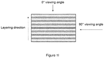
- Figure 1i shows steeper walls (60 degrees to the horizontal plane), which yields more vertical walls 124 than horizontal walls 122, and an increase in facets.
- the surface is comprised entirely of vertical facets with the light source oriented at 90 degrees to the vertical facets.
- the surface facing the incident light has a topography different to the horizontal surfaces 1200a and 1200b and is a multi-laminate structure.
- US5015312 discloses a method and an apparatus for constructing a three-dimensional surface of predetermined shape and color.
- LOM Layered Object Manufacturing
- the present teaching provides a LOM system as detailed in claim 1.
- the present teaching also provides a 3D object gammut mapping method according to claim 14 and a computer software program according to claim 15.
- Advantageous features are provided in the dependent claims.
- LOM Layer Object Manufacturing
- a Layered Object Manufacturing (LOM) system configured to assemble a plurality of individual layers to form a coloured three-dimensional (3D) object.
- the layers are media layers
- the individual media layers may be considered distinct physical elements or entities. In this way they may be individually picked and placed or otherwise transported within the system.
- the layers may be formed in situ during the building of the 3d object for example using a gypsum material. They are individually identifiable but are not formed until the build of the object.
- the system may comprise a printer configured to colour print at least a portion of a first surface of each of a plurality of layers. Where the layers are media layers the system may further comprise a collator configured to assemble the plurality of the individual media layers to form the 3D object. Each of the individual media layers may be individually or independently printed.
- a printing module for printing 3D object media layers for forming a 3D object may be provided.
- the present teaching also provides a LOM system including the printing module and a profiling and layer bonding module for cutting the individual 3D object media layers and bonding the individual layers together to form the finished 3D object.
- a 3D object gamut mapping method for normalizing the overall colour intensity of all surfaces of a 3D object media layer.
- an ink for colour 3D printing is also provides a colour 3D offset printing process for printing additional information on each layer. This information provides error correction and build instructions to the profiling and layer bonding module for profile cutting the stack of colour printed layers.
- the printing module may be a physically separate processing module from the collator that would conventionally form part of a LOM arrangement. Such an example is in our co-assigned application PCT/EP2008/66473 .
- the printing module may comprise an inkjet printer equipped with a duplex module to automatically invert the media when printing on its back surface.
- the printer may be configured to apply the colour prior to collation.
- the colour may also be applied during the collation process.
- the colour is applied through use of different inks.
- the collator may comprise a bonding module configured to bond individual ones of the plurality of media layers.
- the bonding module may be configured to use a water-based adhesive.
- the printer may be configured to print on first and second surfaces of the media layers.
- the printing on first and second surfaces operably reduces image bleed and preserves colour accuracy regardless of angle of the object's surface.
- the printer may be configured to apply multiple colours to one or more surfaces of one or more of the plurality of individual media layers.
- the collator may comprises a profiling module configured to effect a profiling of individual ones of the plurality of media layers to effect a desired 3D shape within the 3D object.
- the profiling module and the bonding module may be integrated in a single profiling and layer bonding module.
- the printing ink utilised within the printing module may be optimised to penetrate most cellulose media types. Examples of such an ink will be described later.
- the colour printing process will now be described in detail.
- a finished 3D object is formed from a stack of individual media layers which are assembled and profiled to form the desired final geometrical shape.
- the individual media layers are sheets of cellulose based paper which may be printed or otherwise treated prior to the assembly arrangement.
- a plurality of 3D object media layers- such as the exemplary cellulose based paper, may be printed in preparation for forming the finished colour 3D printed article.
- the entire layer stack for the colour 3D printed article may be duplex pre-printed off-line in the printing module, after which the printed stack may be loaded into a profiling and layer bonding module where each printed layer may be profiled and bonded to complete the fabrication of the colour 3D printed article.
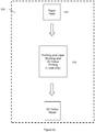
- FIG 2a is a block diagram of a LOM system 500 according to one embodiment of the present teaching.
- the LOM system 500 may comprise a 3D colour printing module 510, a paper feed mechanism 520 and a profiling and layer bonding module 530.
- the layers in this embodiment are media layers and furthermore are a specific form of media, paper.
- Paper may be duplex printed in the 3D colour printing module 510 before being fed into the profiling and layer bonding module 530 via the paper feed mechanism 520 to produce the completed colour 3D object.
- paper may be fed into the 3D colour printing module 510 via the paper feed mechanism 520, and then profiled and bonded in the profiling and layer bonding module 530 to produce the completed colour 3D object.
- the profiling and layer bonding module 530 may comprise separate profiling and layer bonding modules respectively.
- paper may be fed via a paper feed mechanism 520 into an integrated 3D colour printing, profiling and bonding module 540 which performs the printing, profiling and bonding processes, thereby producing a completed colour 3D object.
- printing is performed on one side only of the media.
- FIG. 3 illustrates a printing module 100 for printing a 3D object media layer, according to an embodiment of the present teaching.
- the printing module 100 may be configured to provide application of colour to both sides of the media layer. The colour delivered will therefore migrate from both sides as opposed to techniques where colour is applied from one side only.
- a digital print file containing image, profile and colour information for the 3D object may be generated. This is then sent or otherwise loaded to the printing module 100.
- the digital print file may comprise a series of front-side-rear-side image pairs for each layer of the final stack.
- the colour part of the print file may comprise digital colour image information for both the front side and the rear side for all media layers to be printed.
- Each front-surface-rear-surface-front-surface image sequence may be aligned to one another in the digital file.
- the data set may also include physical front-surface-rear-surface alignment features which may be printed onto the media which allow both human and machine-readable alignment verification tests to be carried out to ensure front-back alignment is maintained during the course of the print run.
- the printing module 100 which typically comprises a housing with specific areas, may be loaded with sufficient blank stock of media for the print task.
- the media may comprise paper.
- the media rear, or trailing, edge and right-side edges may be accurately aligned in the paper tray to ensure that the media location during paper feed is reproduceable.
- Figure 3 illustrates the printing of a front surface image using the printing module 100 according to an embodiment of the present teaching.
- the printing module 100 may be configured for the printing of paper and may include a print head carriage 10, four colour heads 20, paper feed rollers and a paper feed mechanism (not shown), and a duplex unit 30 for inverting the media.
- a print head carriage 10 may include a print head carriage 10, four colour heads 20, paper feed rollers and a paper feed mechanism (not shown), and a duplex unit 30 for inverting the media.
- the media stack may be printed layer by layer- or page by page of paper-, with first and second surfaces of each layer being colour printed, either simultaneouely or in sequence.
- the first and second surfaces of each layer may be opposite to each other.
- the first surface of the layer may be a front planar surface of the layer and the second surface of the layer may be a rear planar surface.
- the media may be driven into the printing module by the paper feed rollers and then curled back or otherwise transported towards the front of the printing module 100 by the paper feed mechanism.
- the media may then be presented to the reciprocating print head carriage, fixed page wide print bar that deposits one or more ink colours which may then print the front surface image.
- FIG. 4 is a diagram illustrating the process of printing the rear surface image of an object media layer which has already had the front surface printed.
- duplex two-sided printing using a single print head carriage that scans across the width of the media layer during printing, followed by the use of a duplex unit which inverts the media layer to allow printing on the underside of the media layer.
- a page-wide array print head may alternatively be used instead of a scanning print head carriage.
- the only moving mechanism is the media feed rollers.
- Another embodiment dispenses with a duplex unit and employs two scanning carriages or two page-wide array print heads printing simultaneously on both sides of the media layer respectively.
- the advantage of this method is that mechanical mis-registration errors between the top and bottom images are eliminated as the media feed mechanism is substantially simplified to a planar media feed path and the two print head movements may be interlocked through sharing the same displacement encoder system.
- the printing may be performed while the media object layer is disposed in a horizontal or vertical plane in the printing module as illustrated in Figure 5 .
- upper and lower print head carriages are utilised at the first and second surfaces of the media layer, respectively.
- Figure 6 illustrates a page-wide array print head 110 for horizontal or vertical simultaneous duplex printing.
- the print head may be integrated into the profiling and layer bonding module, and operate between the paper feed and profiling and layer bonding processes, as a single stage process.
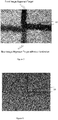
- Test duplex prints may be printed and checked for alignment of the front and rear images by illuminating the rear of the media so that the rear image profile may be illuminated and superimposed on the front surface image.
- Alignment devices such as cross hairs may also be used on both sides of the object media layer to allow the operator to judge how much adjustment of the front and rear images needs to take place to ensure that both images are correctly aligned.
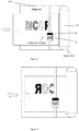
- Figure 7 is a photographic image of an example of alignment devices 50 that may be used to align front and rear images.
- the alignment devices may be designed to align to form a cross-hair when the images on both sides are coincident and there is no misalignment.
- the upper right-hand quadrant is printed on the front of the media layer, and the bottom left quadrant is printed on the rear of the media layer.
- the front image is positioned too much to the right, and higher than the rear image.
- Neither the vertical lines nor the horizontal lines in each of the devices 50 align correctly.
- the letter "M" has been printed on both sides of the media layer and is misaligned.
- printing takes place from both sides of the media layer with sufficient ink to penetrate approximately half way through the thickness of the media later on both sides respectively.
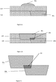
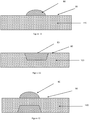
- Figure 10 illustrates ink 80 being deposited onto a front surface 90 of a media layer 120. Sufficient ink 80 may be deposited to penetrate approximately half way through the media layer 120, as shown in Figure 11 .
- the ink makes contact with the media it begins to be absorbed by the media in three dimensions, in the plane of the media (in directions X and Y) and through the thickness of the media.
- the size of the printed dot pixel grows over time, from the initial surface contact dimensions.
- this spread in the dot size is reduced to a value approximately half of the spread in image, had one wanted to print through the entire media thickness layer from one side.
- the stack may be transferred to the profiling and layer bonding module 530.
- the profiling and layer bonding module 530 it is possible to print on a stack of already assembled individual media layers. It is also possible, although not shown, to offset print duplex media layers individually and then immediately feed them into the profiling and bonding module 530.
- the first layer may be placed on the profiling and layer bonding module 530, and that layer may be profile cut with a computer-controlled blade. This cut may provide precise colour edge definition compared to the ragged, liquid-flow edge achieved using inkjet printing alone. Then the next layer may be positioned and bonded on top of the previous layer and then profile cut. The process is continued until all pre-printed layers have been bonded and profile cut in the profiling and layer bonding module 530.
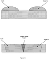
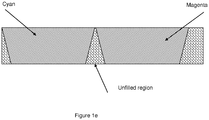
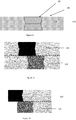
- Figure 14 illustrates two-pre-printed layers 120 and 130 after bonding
- Figure 15 illustrates the edge and colour profile of the two layers 120 and 130 after bonding and profiling or weeding.
- the profiling, or weeding, process comprises removal of unwanted portions of the media layers.
- the mapping functions may be determined empirically for each ink and/or media employed by measuring a number of 3D test pieces with varying wall angles using a colorimeter and plotting colour intensity versus wall angle for a range of wall angles between 0° and 90°. Such a technique is advantageous in a number of different applications. For example, if the raw colour intensity of a vertical surface is measured at 80% of that of a horizontal surface due to the de-saturation described above, the mapping process may reduce the intensity of the horizontal surface by 20% in order to produce uniform colour intensity for an orthogonal 3D shape.
- the background colour may be near-white or approximately colour neutral.
- this does not provide much advantage as saturation adjustment requires modification to all three colour values; i.e. reduce all of R, G, and B for a reduction in colour saturation.
- colour-spaces which employ saturation as one of the coordinates, for example HSV (hue-saturation-value), and HSL (hue-saturation-luminance). If one of these spaces is used then the transform becomes a 2-dimensional function.
- HSV g S i , ⁇
- the function, g, employed here may again be implemented as a polynomial, LUT, etc. as described above, but with the advantage of only a single transformation and lower dimensionality.
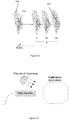
- a calibration step is required of the 3D manufacturing process being used.
- a series of sample colours may be printed on test parts with facets of varying angles. No colour-modification may be used on these parts such that the effect of different angles on different colours may be measured.
- a colour measurement device may then be employed to read the results from each of the facets.
- the colour measurement device may be a colorimeter used in conjunction with an illuminant (e.g. D65), or even a simple flatbed-scanner for lower accuracy results.
- an octagonal test-part is shown in Figure 20 which may provide colour values for 0°, 45°, and 90°, although many more data-points may be required.
- mapping function After sufficient calibration data has been gathered, some initial analysis may be required in order to select the mapping function. If only saturation is modified, for example, the simple 2-dimensional transform described above may be used. Also the mapping function may be selected by examining the data and possibly curve-fitting to a polynomial; alternatively, the raw-data may be inserted into a LUT which may later be interpolated for specific values. The required accuracy of the colour may also be an application-dependent selection factor in the choice of mapping function.
- the example application which has already been detailed is that of paper-based LOM type manufacturing, where the profiling of the physical medium alters the visual effect of the colour.
- the 3D gamut mapping process may, however, be applied to a generality of methods for colouring 3D manufactured objects, where a dependency exists between the angle of a surface and the applied colour.
- Another example may be that of spraying or jet-printing onto different angled surfaces of a finished object. Due to the fact that the ink or paint droplets may be affected by gravity, spraying upwards onto a bottom surface may result in lower ink volume than spraying downward onto a top surface, for example. In this case gamut-mapping may also be applied to normalise the effect.
- the 3D object gamut mapping method may be performed by a 3D object gamut mapping engine integrated in the printing module according to the present teaching.
- the 3D object gamut mapping engine may be implemented using a software solution.
- a computer software program that is executed on a computer or computer network may perform the 3D object gamut mapping method described above.
- the program may be stored on a suitable computer-readable medium in the computer.
- the 3D object gamut mapping engine may be configured to interface with a profiling module to operably identify individual edge surfaces of the 3D object, and to selectively effect an application of colour to those edge surfaces.
- the profiling module is configured to effect a profiling of individual ones of the plurality of media layers to effect a desired 3D shape within the 3D object.
- the computer-readable medium may be a removable storage device or a non-removable storage device, for example, memory cards, magnetic disk drives, magnetic tape drives, and optical drives for memory storage and retrieval on magnetic and optical media.
- Storage media may include volatile and nonvolatile media, both removable and non-removable, and may be provided in any of a number of configurations, for example, RAM, ROM, EEPROM, flash memory, CD-ROM, DVD, or other optical storage medium, magnetic cassettes, magnetic tape, magnetic disk, or other magnetic storage device, or any other memory technology or medium that can be used to store data and can be accessed by a processing unit.
- the 3D object gamut mapping method described above may be stored on the storage device using any method or technology for storage of data, for example, computer readable instructions, data structures, and program modules.
- the storage device may be part of the printing module or LOM system described above.
- the present teaching also provides media, for example paper, and ink for that is optimised for 3D colour printing.
- media for 3D colour printing may be designed with a reduced concentration of sizing agent in the body of the media, and a reduced concentration of sizing agent on the two surfaces of the media.
- the media may be treated during manufacturing, or post-manufacturing with a solution of a non-ionic surfactant such as ethoxylated 2,4,7,9-tetramethyl-5-decyne-4,7-diol, an ethoxylated acetylenic diol making up between 0.1% and 1.0% concentration in water as a post processing surface spray.
- a non-ionic surfactant such as ethoxylated 2,4,7,9-tetramethyl-5-decyne-4,7-diol, an ethoxylated acetylenic diol making up between 0.1% and 1.0% concentration in water as a post processing surface spray.
- the present teaching provides an ink that is designed to be receptive and readily adsorbed by the media throughout the media's thickness. This is achieved by the addition of surfactants that may reduce the surface tension of the ink further, ensuring that the ink is able to penetrate most cellulose media types. This is counter-intuitive to conventional desktop inkjet printing, where it is desirable to retain substantially a colour penetration of the media surface only, leaving the body of the media free of ink.
- the ink composition may include a non-ionic surfactant such as ethoxylated 2,4,7,9-tetramethyl-5-decyne-4,7-diol, an ethoxylated acetylenic diol making up between 0.1% and 1.0% concentration of the ink.
- the balance of the ink composition may include water (75%-85%), water soluble dyes (up to 5%), humectants such as glycerides (up to 5%), anti-bacterials agents, and alcohols (up to 8 %).
- Conventional 2D inkjet ink has a surface tension of 34-38 dynes/cm; however in accordance with the present teaching, for 3D printing it is desirable to reduce the surface tension of the ink to below 30 dynes/cm.
- the addition of 1% of an ethoxylated acetylenic diol has been shown by the present inventors to reduce the surface tension of the ink to a value of approximately 26 dynes/cm, rendering the ink to be rapidly absorbed by the paper.
- Each printed layer may include a sequence code that may be read by the profiling module, and verifies that the layer to be profiled is in the correct sequence.
- Each printed layer may include a code that informs the profiling module what media type is in the sequence.
- Media refers to the substrate that is being used in the 3D fabrication process may be cellulose paper. However other media types may also be employed, and may include, polymer film, metal foils, ceramic powder impregnated paper sheets, metal powder impregnated sheets, polymer powder impregnated sheets, water soluble papers, and substrates made from waxes.
- the code may inform the profiler that a particular layer requires a different profiling recipe (for example, slower cut, or deeper cut due to a thicker or difficult to cut media type).
- the code may inform the profiler that, for example, the next three layers have an identical profile, and to perform a multiple layer cut.
- the media may also include media alignment marks which inform the profiler how to align each media layer relative to the profiler table.
- the material in the tack zone may be colour coded for a number of layers approaching the bond zone.
- Such colour coding might be a red cross-hatched area, which directs the weeding technician to proceed with caution during weeding as permanently bonded layers lie beneath the coloured cross-hatched area.
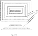
- Figure 16 illustrates a plan and cross-sectional view of a 3D object to be formed after weeding.
- Figure 18 shows a solid 3D printed pyramid structure being revealed as tacked materials are removed.
- the cross hatched regions are represented in Figure 18 by the darker shaded zones. These regions may be carefully removed. Colour codes and/or other marks may be used to indicate proximity to the build object.
- Figure 19 is a photographic image of an example of a colour 3D object during the weeding process
- Figure 20 is a photographic image of the completed colour 3D object after weeding has been performed. It is clear that by delimiting the intended 3D object from the off cut regions through a colouring process it is possible to ensure that the final 3D object is not damaged during the removal of the tacked material.
- the colour printing process described above may be performed in a separate module to the profiling and layer bonding module.
- the printing module may alternatively be integrated into the profiling and layer bonding module, whereby the colour printing process may be performed first, followed by bonding and profiling.
- the printing process is not 'offset' but rather integrated into the assembly process.
- the present teaching further provides a LOM system including the printing module and a separate profiling and layer bonding module for cutting the individual 3D object media layers and bonding the individual layers together to form the finished 3D object.
- the colour printing is "offset" with respect to the bonding and profiling.
- the ink according to the present teaching may be used in the printing module.
- the 3D object gamut mapping method may be performed in the printing module or the LOM system according to the present teaching.
Landscapes
- Engineering & Computer Science (AREA)
- Chemical & Material Sciences (AREA)
- Materials Engineering (AREA)
- Physics & Mathematics (AREA)
- Manufacturing & Machinery (AREA)
- Mechanical Engineering (AREA)
- Optics & Photonics (AREA)
- General Physics & Mathematics (AREA)
- Theoretical Computer Science (AREA)
- General Engineering & Computer Science (AREA)
- Geometry (AREA)
- Computer Hardware Design (AREA)
- Evolutionary Computation (AREA)
- Software Systems (AREA)
- Architecture (AREA)
- Automation & Control Theory (AREA)
- General Chemical & Material Sciences (AREA)
- Chemical Kinetics & Catalysis (AREA)
- Wood Science & Technology (AREA)
- Computational Mathematics (AREA)
- Mathematical Analysis (AREA)
- Mathematical Optimization (AREA)
- Pure & Applied Mathematics (AREA)
- Life Sciences & Earth Sciences (AREA)
- Computer Graphics (AREA)
- Organic Chemistry (AREA)
- Ink Jet (AREA)
- Inks, Pencil-Leads, Or Crayons (AREA)
- Image Processing (AREA)
- Facsimile Image Signal Circuits (AREA)
- Color Image Communication Systems (AREA)
- Ink Jet Recording Methods And Recording Media Thereof (AREA)
- Coating Apparatus (AREA)
Applications Claiming Priority (2)
| Application Number | Priority Date | Filing Date | Title |
|---|---|---|---|
| GB1208993.4A GB2502295B (en) | 2012-05-22 | 2012-05-22 | Colour 3-dimensional printing with 3D gamut mapping |
| PCT/EP2013/025003 WO2014015994A1 (en) | 2012-05-22 | 2013-05-22 | Colour 3-dimensional printing with 3d gamut mapping |
Publications (2)
| Publication Number | Publication Date |
|---|---|
| EP2852491A1 EP2852491A1 (en) | 2015-04-01 |
| EP2852491B1 true EP2852491B1 (en) | 2019-01-09 |
Family
ID=46546475
Family Applications (1)
| Application Number | Title | Priority Date | Filing Date |
|---|---|---|---|
| EP13725284.7A Not-in-force EP2852491B1 (en) | 2012-05-22 | 2013-05-22 | Colour 3-dimensional printing with 3d gamut mapping |
Country Status (10)
| Country | Link |
|---|---|
| US (1) | US10071527B2 (OSRAM) |
| EP (1) | EP2852491B1 (OSRAM) |
| JP (1) | JP6355626B2 (OSRAM) |
| KR (1) | KR20150028776A (OSRAM) |
| CN (1) | CN104470704B (OSRAM) |
| BR (1) | BR112014029298A2 (OSRAM) |
| CA (1) | CA2891021A1 (OSRAM) |
| GB (1) | GB2502295B (OSRAM) |
| RU (1) | RU2014151617A (OSRAM) |
| WO (1) | WO2014015994A1 (OSRAM) |
Cited By (1)
| Publication number | Priority date | Publication date | Assignee | Title |
|---|---|---|---|---|
| CN108335351A (zh) * | 2018-01-26 | 2018-07-27 | 南京大学 | 一种基于定向统计分析的brdf色域映射方法 |
Families Citing this family (54)
| Publication number | Priority date | Publication date | Assignee | Title |
|---|---|---|---|---|
| US9894164B2 (en) * | 2013-06-06 | 2018-02-13 | Samsung Electronics Co., Ltd. | Computing system with control mechanism and method of operation thereof |
| WO2015156877A2 (en) | 2014-01-17 | 2015-10-15 | Graphene 3D Lab Inc. | Fused filament fabrication using multi-segment filament |
| DE102014104321A1 (de) * | 2014-03-27 | 2015-10-01 | Leonhard Kurz Stiftung & Co. Kg | Formkörper und Verfahren zu dessen Herstellung |
| TWI518583B (zh) * | 2014-04-18 | 2016-01-21 | 三緯國際立體列印科技股份有限公司 | 立體列印裝置及其列印異常偵測方法 |
| US10252466B2 (en) | 2014-07-28 | 2019-04-09 | Massachusetts Institute Of Technology | Systems and methods of machine vision assisted additive fabrication |
| WO2016036607A1 (en) | 2014-09-02 | 2016-03-10 | Graphene 3D Lab Inc. | Electrochemical devices comprising nanoscopic carbon materials made by additive manufacturing |
| CN105631058A (zh) * | 2014-10-28 | 2016-06-01 | 张红军 | 基于计算机处理的三维空间的加工方法 |
| GB2535133B (en) | 2014-11-04 | 2019-07-24 | Mcor Tech Limited | Integrated Desktop 3-Dimensional Printing Apparatus |
| GB2535684B (en) * | 2014-11-04 | 2019-04-17 | Mcor Tech Limited | Integrated Desktop 3-Dimensional Printing Apparatus |
| KR101689304B1 (ko) * | 2014-11-19 | 2016-12-23 | 퓨처사이버 주식회사 | 3d 프린터용 필라멘트 조성물 |
| EP3251036B1 (en) * | 2015-01-30 | 2019-08-07 | Hewlett-Packard Development Company, L.P. | Generating configuration data for the production of a three-dimensional object |
| CN105984230B (zh) * | 2015-01-30 | 2019-05-14 | 研能科技股份有限公司 | 快速成型装置的打印模块 |
| CA2978556C (en) | 2015-03-02 | 2022-02-15 | Graphene 3D Lab Inc. | Thermoplastic composites comprising water-soluble peo graft polymers useful for 3-dimensional additive manufacturing |
| KR102309212B1 (ko) * | 2015-03-17 | 2021-10-08 | 한국전자통신연구원 | 3d 프린팅 시뮬레이션 장치 및 방법 |
| RU2017135125A (ru) | 2015-04-20 | 2019-04-05 | Конинклейке Филипс Н.В. | Устройство управления печатью для управления печатью покрывающего слоя на образце |
| US10845780B2 (en) | 2015-04-24 | 2020-11-24 | Hewlett-Packard Development Company, L.P. | Method for setting printing properties of a three-dimensional object for additive manufacturing process |
| US10688724B2 (en) | 2015-04-24 | 2020-06-23 | Hewlett-Packard Development Company, L.P. | Setting properties of three-dimensional objects |
| CN105150530B (zh) * | 2015-04-30 | 2017-09-08 | 北京敏速自动控制设备有限公司 | 三维模型处理方法及其装置、三维打印方法及三维打印设备 |
| CN105082536B (zh) * | 2015-06-26 | 2017-04-19 | 北京金达雷科技有限公司 | 一种光固化3d打印方法 |
| US10611089B2 (en) | 2015-07-28 | 2020-04-07 | Hewlett-Packard Development Company, L.P. | Three-dimensional object property determination |
| US11591467B2 (en) | 2015-07-29 | 2023-02-28 | G6 Materials Corp. | Thermoplastic polymer composites and methods for preparing, collecting, and tempering 3D printable materials and articles from same |
| US10926528B2 (en) * | 2015-07-30 | 2021-02-23 | Hewlett-Packard Development Company, L.P. | Color calibration for three-dimensional printing |
| US10556415B2 (en) | 2015-08-26 | 2020-02-11 | Highcon Systems Ltd | Method and apparatus for building a 3D object from layers of pre-stripped substrate |
| JP7051288B2 (ja) | 2015-12-21 | 2022-04-11 | キヤノン株式会社 | 造形装置、および造形用データを生成するためのデータ処理装置、および立体物の製造方法 |
| US10493697B2 (en) * | 2016-05-31 | 2019-12-03 | Nike, Inc. | Method of printing a contoured object using color and structural layers |
| CN106041078B (zh) * | 2016-07-13 | 2017-11-21 | 北京梦之墨科技有限公司 | 一种彩色金属3d打印线材及其制备方法 |
| WO2018017101A1 (en) * | 2016-07-21 | 2018-01-25 | Hewlett-Packard Development Company, L.P. | Mapping resources |
| DE112016007098T5 (de) * | 2016-07-26 | 2019-04-18 | Hewlett-Packard Development Company, L.P. | Indexierung von voxeln für das 3d-drucken |
| US9764544B1 (en) * | 2016-08-02 | 2017-09-19 | Funai Electric Co., Ltd. | Printer and printing method for three dimensional objects |
| US10328686B2 (en) * | 2016-10-10 | 2019-06-25 | Microsoft Technology Licensing, Llc | Determining print-time for generation of 3D objects based on 3D printing parameters |
| US11207838B2 (en) | 2016-10-27 | 2021-12-28 | Hewlett-Packard Development Company, L.P. | 3D indicator object |
| US10406803B2 (en) * | 2016-12-08 | 2019-09-10 | Xerox Corporation | Method for providing color and material property options in a three-dimensional object printer |
| JP6838953B2 (ja) * | 2016-12-13 | 2021-03-03 | 株式会社ミマキエンジニアリング | 造形方法、造形システム、及び造形装置 |
| US10456984B2 (en) | 2016-12-16 | 2019-10-29 | Massachusetts Institute Of Technology | Adaptive material deposition for additive manufacturing |
| TWI668124B (zh) * | 2017-01-06 | 2019-08-11 | 三緯國際立體列印科技股份有限公司 | 立體列印上色方法與立體列印系統 |
| US10731336B2 (en) | 2017-01-06 | 2020-08-04 | MTRL Design | Method and apparatus for producing three-dimensional topographic acoustic panels |
| JP6880760B2 (ja) * | 2017-01-18 | 2021-06-02 | 富士フイルムビジネスイノベーション株式会社 | 情報処理装置、三次元造形システム、及びプログラム |
| JP6880759B2 (ja) * | 2017-01-18 | 2021-06-02 | 富士フイルムビジネスイノベーション株式会社 | 情報処理装置、三次元造形システム、及びプログラム |
| JP6859715B2 (ja) * | 2017-01-18 | 2021-04-14 | 富士ゼロックス株式会社 | 情報処理装置、三次元造形システム、及び情報処理プログラム |
| JP6891507B2 (ja) * | 2017-01-18 | 2021-06-18 | 富士フイルムビジネスイノベーション株式会社 | 情報処理装置、三次元造形システム、及びプログラム |
| CA3049984A1 (en) * | 2017-01-26 | 2018-08-02 | Nano-Dimension Technologies, Ltd. | Chip embedded printed circuit boards and methods of fabrication |
| CN107696707B (zh) * | 2017-07-07 | 2023-07-25 | 江苏科思机电工程有限公司 | 一种工件上彩色图案的喷印方法及装置 |
| US11724448B2 (en) | 2017-07-17 | 2023-08-15 | Hewlett-Packard Development Company, L.P. | Disguising color in 3D object formation |
| CN110116503A (zh) * | 2018-02-07 | 2019-08-13 | 三纬国际立体列印科技股份有限公司 | 用于3d打印的打印层辅助设计方法 |
| JP7008847B2 (ja) * | 2018-02-26 | 2022-01-25 | ヒューレット-パッカード デベロップメント カンパニー エル.ピー. | 部分塗りつぶし領域のためのキャリッジ遅延 |
| CN108437449B (zh) * | 2018-03-21 | 2020-04-03 | 北京印刷学院 | 3d打印颜色呈现方法、装置及系统 |
| US11273608B2 (en) * | 2018-06-07 | 2022-03-15 | Sakuu Corporation | Multi-material three-dimensional printer |
| WO2019240773A1 (en) * | 2018-06-12 | 2019-12-19 | Hewlett-Packard Development Company, L.P. | Build material management |
| CN110696351A (zh) * | 2018-07-09 | 2020-01-17 | 三纬国际立体列印科技股份有限公司 | 喷墨位置调整方法以及立体打印设备 |
| US11733684B2 (en) | 2018-09-27 | 2023-08-22 | Hewlett-Packard Development Company, L.P. | Overlaying production data on rendered 3D printed object |
| US11312049B2 (en) * | 2019-04-03 | 2022-04-26 | Xerox Corporation | Additive manufacturing system for halftone colored 3D objects |
| US20220186055A1 (en) * | 2019-04-18 | 2022-06-16 | The Johns Hopkins University | Fluoropolymer shear-thinning inks and methods of making and using same |
| US11440317B2 (en) * | 2019-06-28 | 2022-09-13 | Board Of Regents, The University Of Texas System | Line width control and trajectory planning for robot guided inkjet deposition |
| CN116113545A (zh) * | 2020-09-02 | 2023-05-12 | 科迪华公司 | 喷墨打印机控制方法 |
Family Cites Families (24)
| Publication number | Priority date | Publication date | Assignee | Title |
|---|---|---|---|---|
| US5015312A (en) * | 1987-09-29 | 1991-05-14 | Kinzie Norman F | Method and apparatus for constructing a three-dimensional surface of predetermined shape and color |
| JP2000177019A (ja) * | 1998-12-17 | 2000-06-27 | Minolta Co Ltd | 3次元造形物の製造方法 |
| US6506477B1 (en) * | 1998-12-17 | 2003-01-14 | Minolta Co., Ltd. | Apparatus and method for forming three-dimensional object |
| US6730155B2 (en) * | 2000-06-30 | 2004-05-04 | Ricoh Company, Ltd. | Aqueous ink composition |
| HUP0100675A2 (hu) * | 2001-02-09 | 2003-06-28 | Tibor Papp | Sínvégirányító készülék |
| JP2002292752A (ja) * | 2001-03-29 | 2002-10-09 | Minolta Co Ltd | 彩色三次元造形システム及び方法、彩色三次元造形用のデータ処理装置及び方法、彩色三次元造形用のデータ処理プログラム、並びに該データ処理プログラムを記録した記録媒体 |
| US8118419B2 (en) * | 2001-09-20 | 2012-02-21 | Ricoh Company, Ltd. | Ink jet recording method, recording device, ink/recording medium set, recording matter |
| US20040112523A1 (en) * | 2002-10-15 | 2004-06-17 | Crom Elden Wendell | Three dimensional printing from two dimensional printing devices |
| US20040080078A1 (en) * | 2002-10-25 | 2004-04-29 | Collins David C. | Methods and systems for producing a desired apparent coloring in an object produced through rapid prototyping |
| US7229144B2 (en) * | 2002-10-31 | 2007-06-12 | Jeffrey Allen Nielsen | Method for aligning multiple nozzle members in a solid free form fabrication tool |
| US20100174392A1 (en) * | 2003-06-10 | 2010-07-08 | Fink Jeffrey E | Optimal dimensional and mechanical properties of laser sintered hardware by thermal analysis and parameter optimization |
| US8432588B2 (en) * | 2005-10-25 | 2013-04-30 | Hewlett-Packard Development Company, L.P. | Color mapping |
| JP5263584B2 (ja) * | 2007-06-12 | 2013-08-14 | 株式会社リコー | インクジェット記録用インク、インクメディアセット、インクカートリッジ、インクジェット記録装置及びインクジェット記録方法 |
| JP5055205B2 (ja) * | 2007-06-29 | 2012-10-24 | キヤノン株式会社 | 画像複写装置、その制御方法、プログラム、及び3d−lutを生成する方法 |
| GB2455124B (en) * | 2007-11-29 | 2010-07-14 | Finite Engineering Solutions | An adhesive dispensing device |
| US8243334B2 (en) | 2008-06-06 | 2012-08-14 | Virginia Venture Industries, Llc | Methods and apparatuses for printing three dimensional images |
| US8282866B2 (en) | 2008-06-30 | 2012-10-09 | Seiko Epson Corporation | Method and device for forming three-dimensional model, sheet material processing method, and sheet material processing device |
| JP2010074317A (ja) * | 2008-09-16 | 2010-04-02 | Ricoh Co Ltd | 画像処理装置、画像処理プログラム、及び画像処理方法 |
| CN101814188A (zh) * | 2009-06-16 | 2010-08-25 | 黑龙江工程学院 | 基于彩色分量交点的彩色条纹边缘亚像素检测方法 |
| JP2011073163A (ja) * | 2009-09-29 | 2011-04-14 | Brother Industries Ltd | インクジェット記録装置、インクジェット記録方法、インクジェット記録に用いられるプログラム及び立体印刷造形物 |
| US8456709B2 (en) * | 2009-11-17 | 2013-06-04 | Canon Kabushiki Kaisha | Image processing apparatus, image processing method, and lookup table generation method |
| HUP1000675A2 (en) * | 2010-12-17 | 2011-07-28 | Gyoergy Haraszti | Method for producing detachable dental prostheses and such dental prostheses |
| US20110222081A1 (en) * | 2010-03-15 | 2011-09-15 | Chen Yi | Printing Three-Dimensional Objects Using Hybrid Format Data |
| CN103922755B (zh) * | 2014-03-18 | 2016-01-13 | 北京发源动力机械设计研究有限公司 | 3d打印陶瓷零件所用材料及工艺 |
-
2012
- 2012-05-22 GB GB1208993.4A patent/GB2502295B/en not_active Expired - Fee Related
-
2013
- 2013-05-22 RU RU2014151617A patent/RU2014151617A/ru unknown
- 2013-05-22 EP EP13725284.7A patent/EP2852491B1/en not_active Not-in-force
- 2013-05-22 WO PCT/EP2013/025003 patent/WO2014015994A1/en not_active Ceased
- 2013-05-22 US US14/403,061 patent/US10071527B2/en active Active
- 2013-05-22 JP JP2015513047A patent/JP6355626B2/ja not_active Expired - Fee Related
- 2013-05-22 CA CA2891021A patent/CA2891021A1/en not_active Abandoned
- 2013-05-22 CN CN201380038124.2A patent/CN104470704B/zh not_active Expired - Fee Related
- 2013-05-22 BR BR112014029298A patent/BR112014029298A2/pt not_active IP Right Cessation
- 2013-05-22 KR KR1020147036031A patent/KR20150028776A/ko not_active Ceased
Non-Patent Citations (1)
| Title |
|---|
| None * |
Cited By (2)
| Publication number | Priority date | Publication date | Assignee | Title |
|---|---|---|---|---|
| CN108335351A (zh) * | 2018-01-26 | 2018-07-27 | 南京大学 | 一种基于定向统计分析的brdf色域映射方法 |
| CN108335351B (zh) * | 2018-01-26 | 2020-04-21 | 南京大学 | 一种基于定向统计分析的brdf色域映射方法 |
Also Published As
| Publication number | Publication date |
|---|---|
| CN104470704A (zh) | 2015-03-25 |
| KR20150028776A (ko) | 2015-03-16 |
| BR112014029298A2 (pt) | 2017-06-27 |
| GB201208993D0 (en) | 2012-07-04 |
| EP2852491A1 (en) | 2015-04-01 |
| US20150134096A1 (en) | 2015-05-14 |
| JP6355626B2 (ja) | 2018-07-11 |
| CA2891021A1 (en) | 2014-01-30 |
| JP2015528752A (ja) | 2015-10-01 |
| CN104470704B (zh) | 2017-03-22 |
| US10071527B2 (en) | 2018-09-11 |
| RU2014151617A (ru) | 2016-07-10 |
| GB2502295A (en) | 2013-11-27 |
| WO2014015994A1 (en) | 2014-01-30 |
| GB2502295B (en) | 2015-12-09 |
Similar Documents
| Publication | Publication Date | Title |
|---|---|---|
| EP2852491B1 (en) | Colour 3-dimensional printing with 3d gamut mapping | |
| US10254723B2 (en) | Colour 3-dimensional printing | |
| DE102012220622A1 (de) | Medienbasiertes system zum bilden von dreidimensionalen objekten | |
| EP2842304B1 (en) | Methods and systems of generating a lenticular article using a printing blanket | |
| US20050001356A1 (en) | Apparatus for forming a three-dimensional product | |
| JP6902365B2 (ja) | 立体物造形方法及び3次元プリンタ | |
| EP3466646A1 (en) | Shaping device, shaping method, and shaped article | |
| US11179885B2 (en) | Desktop 3-dimensional printing apparatus | |
| JP6705007B2 (ja) | 造形システム、造形方法、及び造形物の製造方法 | |
| CN109177558B (zh) | 一种裸眼3d图案制作方法、制作设备及打印设备 | |
| CN103832104A (zh) | 在3d表面上打印涂层的方法和系统 | |
| JP2018513028A (ja) | フラットベッドプリンタのフラットベッドで媒体にプリントジョブを印刷するための方法及びフラットベッドプリンタ | |
| CN118574735A (zh) | 用于制造装饰构件的方法 | |
| JP2012077446A (ja) | 床構成材の製造方法 | |
| US20210069966A1 (en) | Full color gamut, high resolution three-dimensional object | |
| Parraman | The development of vector based 2.5 D print methods for a painting machine | |
| EP0852542B1 (en) | Improved transparent measuring device and method of making | |
| EP4258098A1 (en) | Method for processing a print job by a printer with less waste | |
| JP2014229920A (ja) | 建材用模様の画像作成方法ならびに画像作成装置 | |
| WO2011131764A1 (de) | Verfahren zur herstellung eines druckerzeugnisses mit einer für blinde oder sehbehinderte durch fühlen wahrnehmbaren darstellung eines graphischen objekts, sowie nach diesem verfahren hergestelltes druckerzeugnis | |
| Parraman et al. | Reproduction of 16th Century Multi-Colour Chiaroscuro Woodblock Prints using Digital Technologies | |
| GB2539644A (en) | Desktop 3-dimensional printing apparatus |
Legal Events
| Date | Code | Title | Description |
|---|---|---|---|
| PUAI | Public reference made under article 153(3) epc to a published international application that has entered the european phase |
Free format text: ORIGINAL CODE: 0009012 |
|
| 17P | Request for examination filed |
Effective date: 20141218 |
|
| AK | Designated contracting states |
Kind code of ref document: A1 Designated state(s): AL AT BE BG CH CY CZ DE DK EE ES FI FR GB GR HR HU IE IS IT LI LT LU LV MC MK MT NL NO PL PT RO RS SE SI SK SM TR |
|
| AX | Request for extension of the european patent |
Extension state: BA ME |
|
| DAX | Request for extension of the european patent (deleted) | ||
| GRAP | Despatch of communication of intention to grant a patent |
Free format text: ORIGINAL CODE: EPIDOSNIGR1 |
|
| STAA | Information on the status of an ep patent application or granted ep patent |
Free format text: STATUS: GRANT OF PATENT IS INTENDED |
|
| INTG | Intention to grant announced |
Effective date: 20170626 |
|
| GRAJ | Information related to disapproval of communication of intention to grant by the applicant or resumption of examination proceedings by the epo deleted |
Free format text: ORIGINAL CODE: EPIDOSDIGR1 |
|
| STAA | Information on the status of an ep patent application or granted ep patent |
Free format text: STATUS: REQUEST FOR EXAMINATION WAS MADE |
|
| GRAP | Despatch of communication of intention to grant a patent |
Free format text: ORIGINAL CODE: EPIDOSNIGR1 |
|
| STAA | Information on the status of an ep patent application or granted ep patent |
Free format text: STATUS: GRANT OF PATENT IS INTENDED |
|
| INTC | Intention to grant announced (deleted) | ||
| INTG | Intention to grant announced |
Effective date: 20171207 |
|
| GRAJ | Information related to disapproval of communication of intention to grant by the applicant or resumption of examination proceedings by the epo deleted |
Free format text: ORIGINAL CODE: EPIDOSDIGR1 |
|
| STAA | Information on the status of an ep patent application or granted ep patent |
Free format text: STATUS: REQUEST FOR EXAMINATION WAS MADE |
|
| GRAP | Despatch of communication of intention to grant a patent |
Free format text: ORIGINAL CODE: EPIDOSNIGR1 |
|
| STAA | Information on the status of an ep patent application or granted ep patent |
Free format text: STATUS: GRANT OF PATENT IS INTENDED |
|
| INTC | Intention to grant announced (deleted) | ||
| INTG | Intention to grant announced |
Effective date: 20180308 |
|
| GRAS | Grant fee paid |
Free format text: ORIGINAL CODE: EPIDOSNIGR3 |
|
| GRAA | (expected) grant |
Free format text: ORIGINAL CODE: 0009210 |
|
| STAA | Information on the status of an ep patent application or granted ep patent |
Free format text: STATUS: THE PATENT HAS BEEN GRANTED |
|
| AK | Designated contracting states |
Kind code of ref document: B1 Designated state(s): AL AT BE BG CH CY CZ DE DK EE ES FI FR GB GR HR HU IE IS IT LI LT LU LV MC MK MT NL NO PL PT RO RS SE SI SK SM TR |
|
| REG | Reference to a national code |
Ref country code: GB Ref legal event code: FG4D |
|
| REG | Reference to a national code |
Ref country code: CH Ref legal event code: EP Ref country code: AT Ref legal event code: REF Ref document number: 1086766 Country of ref document: AT Kind code of ref document: T Effective date: 20190115 |
|
| REG | Reference to a national code |
Ref country code: DE Ref legal event code: R096 Ref document number: 602013049535 Country of ref document: DE |
|
| REG | Reference to a national code |
Ref country code: IE Ref legal event code: FG4D |
|
| REG | Reference to a national code |
Ref country code: NL Ref legal event code: MP Effective date: 20190109 |
|
| REG | Reference to a national code |
Ref country code: LT Ref legal event code: MG4D |
|
| PG25 | Lapsed in a contracting state [announced via postgrant information from national office to epo] |
Ref country code: NL Free format text: LAPSE BECAUSE OF FAILURE TO SUBMIT A TRANSLATION OF THE DESCRIPTION OR TO PAY THE FEE WITHIN THE PRESCRIBED TIME-LIMIT Effective date: 20190109 |
|
| REG | Reference to a national code |
Ref country code: AT Ref legal event code: MK05 Ref document number: 1086766 Country of ref document: AT Kind code of ref document: T Effective date: 20190109 |
|
| PG25 | Lapsed in a contracting state [announced via postgrant information from national office to epo] |
Ref country code: FI Free format text: LAPSE BECAUSE OF FAILURE TO SUBMIT A TRANSLATION OF THE DESCRIPTION OR TO PAY THE FEE WITHIN THE PRESCRIBED TIME-LIMIT Effective date: 20190109 Ref country code: LT Free format text: LAPSE BECAUSE OF FAILURE TO SUBMIT A TRANSLATION OF THE DESCRIPTION OR TO PAY THE FEE WITHIN THE PRESCRIBED TIME-LIMIT Effective date: 20190109 Ref country code: PL Free format text: LAPSE BECAUSE OF FAILURE TO SUBMIT A TRANSLATION OF THE DESCRIPTION OR TO PAY THE FEE WITHIN THE PRESCRIBED TIME-LIMIT Effective date: 20190109 Ref country code: NO Free format text: LAPSE BECAUSE OF FAILURE TO SUBMIT A TRANSLATION OF THE DESCRIPTION OR TO PAY THE FEE WITHIN THE PRESCRIBED TIME-LIMIT Effective date: 20190409 Ref country code: SE Free format text: LAPSE BECAUSE OF FAILURE TO SUBMIT A TRANSLATION OF THE DESCRIPTION OR TO PAY THE FEE WITHIN THE PRESCRIBED TIME-LIMIT Effective date: 20190109 Ref country code: PT Free format text: LAPSE BECAUSE OF FAILURE TO SUBMIT A TRANSLATION OF THE DESCRIPTION OR TO PAY THE FEE WITHIN THE PRESCRIBED TIME-LIMIT Effective date: 20190509 Ref country code: ES Free format text: LAPSE BECAUSE OF FAILURE TO SUBMIT A TRANSLATION OF THE DESCRIPTION OR TO PAY THE FEE WITHIN THE PRESCRIBED TIME-LIMIT Effective date: 20190109 |
|
| PG25 | Lapsed in a contracting state [announced via postgrant information from national office to epo] |
Ref country code: GR Free format text: LAPSE BECAUSE OF FAILURE TO SUBMIT A TRANSLATION OF THE DESCRIPTION OR TO PAY THE FEE WITHIN THE PRESCRIBED TIME-LIMIT Effective date: 20190410 Ref country code: BG Free format text: LAPSE BECAUSE OF FAILURE TO SUBMIT A TRANSLATION OF THE DESCRIPTION OR TO PAY THE FEE WITHIN THE PRESCRIBED TIME-LIMIT Effective date: 20190409 Ref country code: RS Free format text: LAPSE BECAUSE OF FAILURE TO SUBMIT A TRANSLATION OF THE DESCRIPTION OR TO PAY THE FEE WITHIN THE PRESCRIBED TIME-LIMIT Effective date: 20190109 Ref country code: HR Free format text: LAPSE BECAUSE OF FAILURE TO SUBMIT A TRANSLATION OF THE DESCRIPTION OR TO PAY THE FEE WITHIN THE PRESCRIBED TIME-LIMIT Effective date: 20190109 Ref country code: IS Free format text: LAPSE BECAUSE OF FAILURE TO SUBMIT A TRANSLATION OF THE DESCRIPTION OR TO PAY THE FEE WITHIN THE PRESCRIBED TIME-LIMIT Effective date: 20190509 Ref country code: LV Free format text: LAPSE BECAUSE OF FAILURE TO SUBMIT A TRANSLATION OF THE DESCRIPTION OR TO PAY THE FEE WITHIN THE PRESCRIBED TIME-LIMIT Effective date: 20190109 |
|
| REG | Reference to a national code |
Ref country code: DE Ref legal event code: R097 Ref document number: 602013049535 Country of ref document: DE |
|
| PG25 | Lapsed in a contracting state [announced via postgrant information from national office to epo] |
Ref country code: AT Free format text: LAPSE BECAUSE OF FAILURE TO SUBMIT A TRANSLATION OF THE DESCRIPTION OR TO PAY THE FEE WITHIN THE PRESCRIBED TIME-LIMIT Effective date: 20190109 Ref country code: AL Free format text: LAPSE BECAUSE OF FAILURE TO SUBMIT A TRANSLATION OF THE DESCRIPTION OR TO PAY THE FEE WITHIN THE PRESCRIBED TIME-LIMIT Effective date: 20190109 Ref country code: EE Free format text: LAPSE BECAUSE OF FAILURE TO SUBMIT A TRANSLATION OF THE DESCRIPTION OR TO PAY THE FEE WITHIN THE PRESCRIBED TIME-LIMIT Effective date: 20190109 Ref country code: DK Free format text: LAPSE BECAUSE OF FAILURE TO SUBMIT A TRANSLATION OF THE DESCRIPTION OR TO PAY THE FEE WITHIN THE PRESCRIBED TIME-LIMIT Effective date: 20190109 Ref country code: RO Free format text: LAPSE BECAUSE OF FAILURE TO SUBMIT A TRANSLATION OF THE DESCRIPTION OR TO PAY THE FEE WITHIN THE PRESCRIBED TIME-LIMIT Effective date: 20190109 Ref country code: IT Free format text: LAPSE BECAUSE OF FAILURE TO SUBMIT A TRANSLATION OF THE DESCRIPTION OR TO PAY THE FEE WITHIN THE PRESCRIBED TIME-LIMIT Effective date: 20190109 Ref country code: CZ Free format text: LAPSE BECAUSE OF FAILURE TO SUBMIT A TRANSLATION OF THE DESCRIPTION OR TO PAY THE FEE WITHIN THE PRESCRIBED TIME-LIMIT Effective date: 20190109 Ref country code: SK Free format text: LAPSE BECAUSE OF FAILURE TO SUBMIT A TRANSLATION OF THE DESCRIPTION OR TO PAY THE FEE WITHIN THE PRESCRIBED TIME-LIMIT Effective date: 20190109 |
|
| PLBE | No opposition filed within time limit |
Free format text: ORIGINAL CODE: 0009261 |
|
| STAA | Information on the status of an ep patent application or granted ep patent |
Free format text: STATUS: NO OPPOSITION FILED WITHIN TIME LIMIT |
|
| PG25 | Lapsed in a contracting state [announced via postgrant information from national office to epo] |
Ref country code: SM Free format text: LAPSE BECAUSE OF FAILURE TO SUBMIT A TRANSLATION OF THE DESCRIPTION OR TO PAY THE FEE WITHIN THE PRESCRIBED TIME-LIMIT Effective date: 20190109 |
|
| 26N | No opposition filed |
Effective date: 20191010 |
|
| REG | Reference to a national code |
Ref country code: CH Ref legal event code: PL |
|
| PG25 | Lapsed in a contracting state [announced via postgrant information from national office to epo] |
Ref country code: LI Free format text: LAPSE BECAUSE OF NON-PAYMENT OF DUE FEES Effective date: 20190531 Ref country code: CH Free format text: LAPSE BECAUSE OF NON-PAYMENT OF DUE FEES Effective date: 20190531 Ref country code: MC Free format text: LAPSE BECAUSE OF FAILURE TO SUBMIT A TRANSLATION OF THE DESCRIPTION OR TO PAY THE FEE WITHIN THE PRESCRIBED TIME-LIMIT Effective date: 20190109 |
|
| REG | Reference to a national code |
Ref country code: BE Ref legal event code: MM Effective date: 20190531 |
|
| PG25 | Lapsed in a contracting state [announced via postgrant information from national office to epo] |
Ref country code: LU Free format text: LAPSE BECAUSE OF NON-PAYMENT OF DUE FEES Effective date: 20190522 Ref country code: SI Free format text: LAPSE BECAUSE OF FAILURE TO SUBMIT A TRANSLATION OF THE DESCRIPTION OR TO PAY THE FEE WITHIN THE PRESCRIBED TIME-LIMIT Effective date: 20190109 |
|
| PGFP | Annual fee paid to national office [announced via postgrant information from national office to epo] |
Ref country code: FR Payment date: 20191120 Year of fee payment: 7 |
|
| PG25 | Lapsed in a contracting state [announced via postgrant information from national office to epo] |
Ref country code: TR Free format text: LAPSE BECAUSE OF FAILURE TO SUBMIT A TRANSLATION OF THE DESCRIPTION OR TO PAY THE FEE WITHIN THE PRESCRIBED TIME-LIMIT Effective date: 20190109 |
|
| PG25 | Lapsed in a contracting state [announced via postgrant information from national office to epo] |
Ref country code: IE Free format text: LAPSE BECAUSE OF NON-PAYMENT OF DUE FEES Effective date: 20190522 |
|
| PG25 | Lapsed in a contracting state [announced via postgrant information from national office to epo] |
Ref country code: BE Free format text: LAPSE BECAUSE OF NON-PAYMENT OF DUE FEES Effective date: 20190531 |
|
| PG25 | Lapsed in a contracting state [announced via postgrant information from national office to epo] |
Ref country code: FR Free format text: LAPSE BECAUSE OF NON-PAYMENT OF DUE FEES Effective date: 20200531 |
|
| PG25 | Lapsed in a contracting state [announced via postgrant information from national office to epo] |
Ref country code: CY Free format text: LAPSE BECAUSE OF FAILURE TO SUBMIT A TRANSLATION OF THE DESCRIPTION OR TO PAY THE FEE WITHIN THE PRESCRIBED TIME-LIMIT Effective date: 20190109 |
|
| PG25 | Lapsed in a contracting state [announced via postgrant information from national office to epo] |
Ref country code: MT Free format text: LAPSE BECAUSE OF FAILURE TO SUBMIT A TRANSLATION OF THE DESCRIPTION OR TO PAY THE FEE WITHIN THE PRESCRIBED TIME-LIMIT Effective date: 20190109 Ref country code: HU Free format text: LAPSE BECAUSE OF FAILURE TO SUBMIT A TRANSLATION OF THE DESCRIPTION OR TO PAY THE FEE WITHIN THE PRESCRIBED TIME-LIMIT; INVALID AB INITIO Effective date: 20130522 |
|
| PG25 | Lapsed in a contracting state [announced via postgrant information from national office to epo] |
Ref country code: MK Free format text: LAPSE BECAUSE OF FAILURE TO SUBMIT A TRANSLATION OF THE DESCRIPTION OR TO PAY THE FEE WITHIN THE PRESCRIBED TIME-LIMIT Effective date: 20190109 |
|
| PGFP | Annual fee paid to national office [announced via postgrant information from national office to epo] |
Ref country code: GB Payment date: 20220526 Year of fee payment: 10 Ref country code: DE Payment date: 20220525 Year of fee payment: 10 |
|
| REG | Reference to a national code |
Ref country code: DE Ref legal event code: R119 Ref document number: 602013049535 Country of ref document: DE |
|
| GBPC | Gb: european patent ceased through non-payment of renewal fee |
Effective date: 20230522 |
|
| PG25 | Lapsed in a contracting state [announced via postgrant information from national office to epo] |
Ref country code: DE Free format text: LAPSE BECAUSE OF NON-PAYMENT OF DUE FEES Effective date: 20231201 Ref country code: GB Free format text: LAPSE BECAUSE OF NON-PAYMENT OF DUE FEES Effective date: 20230522 |