EP2852330B1 - Faden-anker - Google Patents
Faden-anker Download PDFInfo
- Publication number
- EP2852330B1 EP2852330B1 EP13723793.9A EP13723793A EP2852330B1 EP 2852330 B1 EP2852330 B1 EP 2852330B1 EP 13723793 A EP13723793 A EP 13723793A EP 2852330 B1 EP2852330 B1 EP 2852330B1
- Authority
- EP
- European Patent Office
- Prior art keywords
- pin
- support
- suture
- thread
- ultrasonic applicator
- Prior art date
- Legal status (The legal status is an assumption and is not a legal conclusion. Google has not performed a legal analysis and makes no representation as to the accuracy of the status listed.)
- Active
Links
Images


Classifications
-
- A—HUMAN NECESSITIES
- A61—MEDICAL OR VETERINARY SCIENCE; HYGIENE
- A61B—DIAGNOSIS; SURGERY; IDENTIFICATION
- A61B17/00—Surgical instruments, devices or methods
- A61B17/04—Surgical instruments, devices or methods for suturing wounds; Holders or packages for needles or suture materials
- A61B17/0401—Suture anchors, buttons or pledgets, i.e. means for attaching sutures to bone, cartilage or soft tissue; Instruments for applying or removing suture anchors
-
- A—HUMAN NECESSITIES
- A61—MEDICAL OR VETERINARY SCIENCE; HYGIENE
- A61B—DIAGNOSIS; SURGERY; IDENTIFICATION
- A61B17/00—Surgical instruments, devices or methods
- A61B17/00491—Surgical glue applicators
-
- A—HUMAN NECESSITIES
- A61—MEDICAL OR VETERINARY SCIENCE; HYGIENE
- A61B—DIAGNOSIS; SURGERY; IDENTIFICATION
- A61B17/00—Surgical instruments, devices or methods
- A61B17/00491—Surgical glue applicators
- A61B2017/005—Surgical glue applicators hardenable using external energy source, e.g. laser, ultrasound
-
- A—HUMAN NECESSITIES
- A61—MEDICAL OR VETERINARY SCIENCE; HYGIENE
- A61B—DIAGNOSIS; SURGERY; IDENTIFICATION
- A61B17/00—Surgical instruments, devices or methods
- A61B2017/00831—Material properties
- A61B2017/00955—Material properties thermoplastic
-
- A—HUMAN NECESSITIES
- A61—MEDICAL OR VETERINARY SCIENCE; HYGIENE
- A61B—DIAGNOSIS; SURGERY; IDENTIFICATION
- A61B17/00—Surgical instruments, devices or methods
- A61B17/04—Surgical instruments, devices or methods for suturing wounds; Holders or packages for needles or suture materials
- A61B17/0401—Suture anchors, buttons or pledgets, i.e. means for attaching sutures to bone, cartilage or soft tissue; Instruments for applying or removing suture anchors
- A61B2017/0403—Dowels
-
- A—HUMAN NECESSITIES
- A61—MEDICAL OR VETERINARY SCIENCE; HYGIENE
- A61B—DIAGNOSIS; SURGERY; IDENTIFICATION
- A61B17/00—Surgical instruments, devices or methods
- A61B17/04—Surgical instruments, devices or methods for suturing wounds; Holders or packages for needles or suture materials
- A61B17/0401—Suture anchors, buttons or pledgets, i.e. means for attaching sutures to bone, cartilage or soft tissue; Instruments for applying or removing suture anchors
- A61B2017/0404—Buttons
-
- A—HUMAN NECESSITIES
- A61—MEDICAL OR VETERINARY SCIENCE; HYGIENE
- A61B—DIAGNOSIS; SURGERY; IDENTIFICATION
- A61B17/00—Surgical instruments, devices or methods
- A61B17/04—Surgical instruments, devices or methods for suturing wounds; Holders or packages for needles or suture materials
- A61B17/0401—Suture anchors, buttons or pledgets, i.e. means for attaching sutures to bone, cartilage or soft tissue; Instruments for applying or removing suture anchors
- A61B2017/0409—Instruments for applying suture anchors
Definitions
- the invention relates to a method and a device for anchoring a thread to an object.
- the invention relates to a method and apparatus for anchoring a thread to an object using ultrasonic vibrations.
- the WO 00/02489 discloses a kit for joining one or more threads.
- the kit includes a melt collar and a fixing tool that compresses the collar around the threads so that the threads are held securely in the collar and overlap portions of the collar.
- the fixing tool applies energy to the collar to fuse the overlapping portions of the collar around the threads.
- the fixation tool generally consists of an energy source, a welding head, an end effector, and electronics for activating the end effector.
- the US 5,993,458 describes an externally threaded bone anchor that can remain therein after insertion into a bone and can form a platform for receiving tissue, as well as a method of ultrasonically embedding the bone anchor in the bone with and without pre-drilling an anchor receiving hole.
- the bone anchor can be attached to the tip of an ultrasonic sonotrode and screwed into the bone using ultrasound energy.
- a device for anchoring a thread to an object has a pin.
- the pin can be made of a material, for example a suitable polymer, which is liquefiable by means of ultrasonic vibrations.
- at least one thread can be connected to the pin, wherein the at least one thread may be attached to a rear end of the pin.
- the pin can have a diameter of 2.8mm and a length of 7mm.
- the pin has a body with a longitudinal extent (length) and a transverse extent (cross-section, diameter), wherein the pin can be preferably inserted or inserted in the direction of the longitudinal extent in an opening or recess in an object.
- the front end of the pin may be tapered or chamfered.
- the rear end of the pin is therefore that end which is in the insertion direction behind the pin.
- the thread can be firmly connected to it, for example, by pouring into the pin, but the thread can also be passed through an opening (a transverse hole, a thread eye) or fixed to the pin by means of a hook or a clamping fork can.
- the device further comprises a carrier with a carrier body and at least one carrier arm, wherein the carrier arm is adapted to releasably hold the pin in a predetermined position relative to the carrier body.
- the carrier may further comprise a thread take-up for receiving the thread.
- a pin With the aid of a carrier a pin can be held together with a thread such that the pin (even if the pin is relatively small) can be reliably inserted into a hole in an object without causing any conflict with the thread, which is connected to the pen.
- the device further comprises a protective cap which can be connected to the carrier in such a way that a pin held by the carrier arm is covered.
- a protective cap which can be connected to the carrier in such a way that a pin held by the carrier arm is covered.
- the cover of the pin by a protective cap can be particularly advantageous in the field of medical applications, since not only damage to the pin but also contamination during transport of the pin (on the carrier) can be prevented.
- the device further comprises an ultrasonic applicator with a sonotrode.
- the ultrasonic applicator can be releasably connected to the carrier in such a way that the tip of the sonotrode can be brought into contact with the pin held by the carrier arm.
- a carrier with pin can be placed on an ultrasonic applicator such that the sonotrode tip is in contact with the rear end of the pin.
- the pin which is held by the carrier, which in turn is connected to the ultrasonic applicator can be safely inserted into a bore in an object and with the aid of ultrasonic vibrations that can be generated by the ultrasonic applicator, liquefied or at least be made soft so that the material of the pin can be reliably connected to the material of the object or can be anchored to this.
- the ultrasonic applicator has a latch, wherein the carrier can be locked by means of the latch on the ultrasonic applicator.
- the bolt can also be designed so that a protective cap can be releasably connected to the ultrasonic applicator.
- the support of the device comprises two support arms which are arranged such that the pin can be held between the two support arms, wherein the support arms can be designed such that the tip of a sonotrode can be arranged between the support arms.
- a thread take-up can be provided on the carrier body. When two threads are connected to the pin, a respective thread along a support arm can be guided to the thread take-up and be included in this, as long as the pin is held by the support arms.
- the device further comprises a needle which may be attached to a free end of the thread.
- a pin with two threads in a hole can be used, which was previously formed in the bone.
- the material of the pin can now be at least partially melted, so that the pin is securely anchored in the bone.
- the sutures can be used to attach soft tissue structures to the bone.
- the attachment of the soft tissue structures can be further simplified if at least one needle is fixed to a free end of a thread. The needle may be cut off and thus removed after attachment of the soft tissue structures together with an excess length of the thread.
- it may be intended to attach one or more threads to an object made of stone, earthenware, wood or a plastic.
- FIG. 1 shows a protective cap 30 in which a carrier 20 is arranged.
- the protective cap 30 is formed by a hollow body which on the one hand has an annular region and on the other hand has a frustoconical region.
- the outer surfaces of the protective cap have grooves or ribs which facilitate holding and handling of the protective cap.
- the protective cap 30 may also be formed with a different outer shape, as long as a cavity is formed, which is adapted to receive a carrier together with a pin.
- FIG. 2 shows a carrier 20, which has an annular support body 24, two support arms 22 and a thread take-up 26.
- a thread 12 is guided along a carrier arm 22 in the direction of the carrier body 24 and received in the thread receiving 26.
- the thread take-up 26 may be designed such that a free end of a thread can be clamped and thus secured.
- the thread receiving 26 may be designed so that a needle (not shown) can be accommodated, which is fixed to the free end of the thread.
- FIG. 3 shows an ultrasonic applicator 40 having at one end a sonotrode 42 with a sonotrode tip 44.
- the sonotrode 42 projects from the housing of the ultrasonic applicator 40.
- an ultrasonic generator housed with the sonotrode 42nd is connected so that vibrations generated by the ultrasonic generator, can be passed to the sonotrode.
- a combination of carrier 20 and protective cap 30 is attached to the ultrasonic applicator 40.
- a latch 46 is provided, which is designed so that by means of the bolt 46, the protective cap 30 as well as the carrier can be releasably locked to the housing of the ultrasonic applicator.
- the latch 46 may be operable such that the protective cap 30, but not the carrier 20, is detachable from the ultrasonic applicator 40.
- FIG. 5 shows a state in which a carrier having no protective cap is connected to the ultrasonic applicator 40.
- the carrier body 24 can be locked by the latch 46 on the ultrasonic applicator.
- the support arms 22 hold the pin 10 relative to the ultrasonic applicator and thus to the sonotrode 42 such that the sonotrode tip 44 is in contact with the trailing end of the pin 10. This contact is necessary so that vibrations of the sonotrode can be transferred to the material of the pin.
- FIG. 6 shows a situation in which the pin 10 is kept aligned with an opening 52 in an object 50.
- the opening 52 may be a bore or a suitable recess, wherein the pin 10 has a diameter or a cross-sectional shape that matches the diameter of the bore or the shape of the recess.
- the material of the pin can be melted by ultrasonic vibrations, at least made soft, so that the material of the founder 10, the opening 52 including the Surface roughness fills, whereby the pin 10 is firmly anchored in the opening.
- the opening 52 may be formed, for example, also angular, star-shaped or oval.
- the fact that the material of the pin 10 is melted makes it possible for a complementarily shaped pin to fill the opening 52, even if the cross-sectional shape of the pin does not coincide with that of the opening.
- This aspect is also facilitated by the fact that the pin is merely inserted into the opening, i.e., the pin is only moved in the longitudinal direction or insertion direction, and does not have to be rotated, such as a screw.
- FIG. 7 shows a state in which the pin 10 is already firmly anchored in the object 50 and the ultrasonic applicator was removed with the sonotrode.
- the thread 12 can be released in the thread take-up, so that the carrier 20 can be separated from the pin and the thread.
- FIG. 8 shows a pin 10 which is anchored in an object 50, wherein at the rear end of the pin 10 two threads 12 protrude.
- anchor threads to an object such that the surface of the object 50 can be flush with the posterior end of a founder.
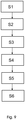
- the flowchart in FIG. 9 illustrates steps of a method of anchoring a thread to an object. It is noted that the steps related to the procedure and also to FIG. 9 are main steps, these main steps may be differentiated and / or sub-divided. There may also be further sub-steps between the main steps. However, a sub-step is only mentioned if this step is important to understanding the principles of the method according to the invention.
- step S1 a pin is provided, at the rear end of which a thread is fastened, wherein the pin is made of a material which is liquefiable by means of ultrasonic vibrations.
- step S2 the pen is held by means of a carrier.
- the pin is releasably attached to the carrier.
- step S3 the carrier is connected to an ultrasonic applicator, so that a tip of a sonotrode of the ultrasonic applicator can be brought into contact with the pin.
- the carrier can be attached to the front of the ultrasonic applicator and optionally locked.
- step S4 the pin is inserted into a hole in an object. That is, the pin may be attached to the carrier such that the tip of the pin protrudes. In this way, even a very small pen is manageable.
- step S5 the material of the pen is liquefied, or at least softened, by means of ultrasonic vibrations that may be generated by the ultrasonic applicator so that the pin is anchored to the object, for example, due to penetration of the material of the pin into gaps and Pores in the object.
- step S6 after anchoring the pin to the object, the thread can be released from a thread take-up.
- the thread take-up can be provided on the carrier so that the thread can be taken up in the thread take-up in step S2 and held in steps S3 to S5 in this, so that unintentional entanglement and / or knotting can be avoided.
Landscapes
- Health & Medical Sciences (AREA)
- Surgery (AREA)
- Life Sciences & Earth Sciences (AREA)
- Medical Informatics (AREA)
- Animal Behavior & Ethology (AREA)
- Engineering & Computer Science (AREA)
- Biomedical Technology (AREA)
- Heart & Thoracic Surgery (AREA)
- Veterinary Medicine (AREA)
- Molecular Biology (AREA)
- Nuclear Medicine, Radiotherapy & Molecular Imaging (AREA)
- General Health & Medical Sciences (AREA)
- Public Health (AREA)
- Rheumatology (AREA)
- Surgical Instruments (AREA)
- Lining Or Joining Of Plastics Or The Like (AREA)
- Treatment Of Fiber Materials (AREA)
Description
- Die Erfindung betrifft ein Verfahren und eine Vorrichtung zum Verankern eines Fadens an einem Objekt. Insbesondere betrifft die Erfindung ein Verfahren und eine Vorrichtung zum Verankern eines Fadens an einem Objekt unter Verwendung von Ultraschallschwingungen.
- Um einen Faden an einem Objekt zu befestigen, insbesondere an einer Fläche eines Objekts, kann zum Beispiel mittels einer Schraube ein Faden zwischen Schraube und Objekt verklemmt werden. Diese Möglichkeit hat jedoch den Nachteil, dass der Faden nicht zuverlässig befestigt werden kann oder möglicherweise beschädigt wird.
- Alternative ist bekannt, einen Faden vorab fest mit einer Schraube zu verbinden und dann diese Schraube in eine Bohrung in einem Objekt einzuschrauben. Die Handhabung einer derartigen Schrauben-Faden-Kombination ist jedoch umständlich, solange das freie Fadenende frei beweglich ist, während die Schraube eingeschraubt wird. Um diesen Nachteil zu überwinden, gibt es Systeme, bei welchen eine Schraube zusammen mit zumindest einem Faden lösbar verbunden mit einem geeigneten Werkzeug vor-konfektioniert bereitgestellt wird. Diese Variante ist jedoch teuer aufgrund des mit jeder Schraube mitzuliefernden Werkzeugs. Die
WO 00/02489 US 5,993,458 beschreibt einen Knochenanker mit Außengewinde, der nach dem Einsetzen in einen Knochen in diesem bleiben kann und eine Plattform zur Aufnahme von Gewebe bilden kann, sowie ein Verfahren zur Ultraschall-Einbettung des Knochenankers in den Knochen mit und auch ohne Vorbohren eines Ankeraufnahmelochs. Der Knochenanker kann hierbei an der Spitze einer Ultraschall-Sonotrode befestigt werden und unter Verwendung von Ultraschallenergie in den Knochen eingeschraubt werden. - Es ist eine Aufgabe der Erfindung, ein Verfahren und eine Vorrichtung zum Verankern eines Fadens an einem Objekt bereitzustellen. Es kann als weitere Aufgaben angesehen werden, eine verbesserte Handhabung der Vorrichtung und eine zuverlässige und sichere Verankerung eines Fadens an einem Objekt zu gewährleisten.
- Diese und weitere Aufgaben werden durch den jeweiligen Gegenstand der unabhängigen Ansprüche erfüllt. Weitere Ausführungsformen sind den jeweiligen abhängigen Ansprüchen zu entnehmen.
- Im Allgemeinen weist eine Vorrichtung zum Verankern eines Fadens an einem Objekt einen Stift auf. Der Stift kann aus einem Material, beispielsweise einem geeigneten Polymer hergestellt sein, welches mittels Ultraschallschwingungen verflüssigbar ist. Ferner kann zumindest ein Faden mit dem Stift verbunden sein, wobei der zumindest eine Faden an einem hinteren Ende des Stifts befestigt sein kann. Der Stift kann beispielsweise einen Durchmesser von 2,8mm und eine Länge von 7mm haben.
- Der Stift weist einen Körper mit einer Längsausdehnung (Länge) und einer Querausdehnung (Querschnitt, Durchmesser) auf, wobei der Stift vorzugsweise in Richtung der Längsausdehnung in eine Öffnung oder Aussparung in einem Objekt eingeführt bzw. eingesetzt werden kann. Zum leichteren Einführen kann das vordere Ende des Stifts verjüngt oder angeschrägt sein. Das hintere Ende des Stifts ist demnach dasjenige Ende, welches in Einführrichtung hinten an dem Stift ist.
- Durch eine Fixierung des Fadens am hinteren Ende kann gewährleistet werden, dass der Faden beim Einführen des Stifts und damit beim Verankern nicht beschädigt wird. Es wird angemerkt, dass der Faden beispielsweise durch Eingießen beim Herstellen des Stiftes fest mit diesem verbunden werden kann, dass der Faden aber auch durch eine Öffnung (ein Querloch, ein Fadenauge) hindurch geführt oder mittels eines Hakens oder einer Klemmgabel an dem Stift fixiert werden kann.
- Gemäß einer Ausführungsform weist die Vorrichtung ferner einen Träger mit einem Trägerkörper und zumindest einem Trägerarm auf, wobei der Trägerarm geeignet ist, den Stift in einer vorbestimmten Lage relative zum Trägerkörper lösbar zu halten.
- Gemäß einer Ausführungsform kann der Träger ferner eine Fadenaufnahme zum Aufnehmen des Fadens aufweisen.
- Mit Hilfe eines Trägers kann ein Stift zusammen mit einem Faden derart gehalten werden, dass der Stift (selbst wenn der Stift relative klein ist) zuverlässig in eine Bohrung in einem Objekt eingeführt werden kann, ohne dass es zu irgend einem Konflikt mit dem Faden kommt, welcher mit dem Stift verbunden ist.
- Gemäß einer weiteren Ausführungsform weist die Vorrichtung ferner eine Schutzkappe auf, welche derart mit dem Träger verbindbar ist, dass ein von dem Trägerarm gehaltene Stift abgedeckt ist. Die Abdeckung des Stiftes durch eine Schutzkappe kann insbesondere im Bereich medizinischer Anwendungen vorteilhaft sein, da nicht nur Beschädigungen des Stiftes sondern auch Verschmutzungen beim Transport des Stiftes (am Träger) verhindert werden können.
- Gemäß einer anderen Ausführungsform weist die Vorrichtung ferner einen Ultraschall-Applikator mit einer Sonotrode auf. Der Ultraschall-Applikator kann lösbar und derart mit dem Träger verbindbar sein, dass die Spitze der Sonotrode in Kontakt mit dem von dem Trägerarm gehaltenen Stift bringbar ist.
- Mit anderen Worten, ein Träger mit Stift kann derart an einem Ultraschall-Applikator angeordnet werden, dass die Sonotrodenspitze in Kontakt mit dem hinteren Ende des Stifts ist. Damit kann der Stift, der von dem Träger gehalten wird, welcher wiederum mit dem Ultraschall-Applikator verbunden ist, sicher in eine Bohrung in einem Objekt eingeführt werden und mit Hilfe von Ultraschallschwingungen, die von dem Ultraschall-Applikator erzeugt werden können, verflüssigt oder zumindest weich gemacht werden, sodass das Material des Stiftes zuverlässig mit dem Material des Objektes verbunden werden kann bzw. an diesem verankert werden kann.
- Gemäß einer Ausführungsform weist der Ultraschall-Applikator einen Riegel auf, wobei der Träger mittels des Riegels an dem Ultraschall-Applikator arretiert werden kann. Der Riegel kann darüber hinaus so gestaltet sein, dass auch eine Schutzkappe lösbar mit dem Ultraschall-Applikator verbunden werden kann.
- Gemäß einer Ausführungsform weist der Träger der Vorrichtung zwei Trägerarme auf, die derart angeordnet sind, dass der Stift zwischen den zwei Trägerarmen gehalten werden kann, wobei die Trägerarme derart gestaltet sein können, dass auch die Spitze einer Sonotrode zwischen den Trägerarmen angeordnet werden kann. Ferner kann eine Fadenaufnahme an dem Trägerkörper vorgesehen sein. Wenn zwei Fäden mit dem Stift verbunden sind, kann jeweils ein Faden entlang eines Trägerarms zu der Fadenaufnahme hin geführt sein und in dieser aufgenommen sein, solange der Stift von den Trägerarmen gehalten wird.
- Gemäß einer weiteren Ausführungsform weist die Vorrichtung ferner eine Nadel auf, welche an einem freien Ende des Fadens befestigt sein kann.
- Beispielsweise kann es beabsichtigt sein, zwei Fäden an einer Oberfläche eines Knochens zu befestigen. Hierzu kann ein Stift mit zwei Fäden in eine Bohrung eingesetzt werden, die vorab in dem Knochen ausgebildet wurde. Mit Hilfe von Ultraschallschwingungen kann nun das Material des Stiftes zumindest teilweise geschmolzen werden, sodass der Stift sicher in dem Knochen verankert wird. Auf diese Weise sind die zwei Fäden an dem Knochen verankert. Die Fäden können verwendet werden, um Weichgewebestrukturen an dem Knochen zu befestigen. Die Befestigung der Weichgewebestrukturen kann zusätzlich vereinfacht werden, wenn zumindest eine Nadel an einem freien Ende eines Fadens fixiert ist. Die Nadel kann nach einer Befestigung der Weichgewebestrukturen zusammen mit einer Überlänge des Fadens abgeschnitten und damit entfernt werden.
- Alternative kann es beabsichtigt sein, einen oder mehrere Fäden an einem Objekt aus Stein, Steingut, Holz oder einem Kunststoff zu befestigen.
- Die oben beschriebenen Aspekte und weitere Aspekte, Merkmale und Vorteile der Erfindung können ebenfalls aus den Beispielen der Ausführungsformen entnommen werden, welche im Folgenden unter Bezugnahme auf die anhängenden Zeichnungen beschrieben werden.
-
-
Fig. 1 zeigt einen Träger mit einer Schutzkappe. -
Fig. 2 zeigt einen Träger zusammen mit einem Stift mit Faden. -
Fig. 3 zeigt einen Ultraschall-Applikator. -
Fig. 4 zeigt einen Träger mit Schutzkappe an einem Ultraschall-Applikator. -
Fig. 5 zeigt einen Träger mit Stift an einem Ultraschall-Applikator. -
Fig. 6 zeigt, wie ein Stift in eine Bohrung eingesetzt wird. -
Fig. 7 zeigt einen Träger mit einem in einer Bohrung verankerten Stift. -
Fig. 8 zeigt eine in einer Bohrung verankerten Stift mit zwei Fäden. -
Fig. 9 ist ein Flussdiagramm, welches Schritte eines Verfahrens zum Verankern eines Fadens an einem Objekt zeigt. - Es wird angemerkt, dass die Darstellungen in den Zeichnungen lediglich schematisch sind und keinen Hinweis geben sollen auf mögliche Größenverhältnisse. In den Figuren sind gleiche oder ähnliche Aspekte mit gleichen Bezugszeichen versehen.
-
Figur 1 zeigt eine Schutzkappe 30, in welcher ein Träger 20 angeordnet ist. Die Schutzkappe 30 wird durch einen Hohlkörper gebildet, der einerseits einen ringförmigen Bereich und andererseits einen kegelstumpfförmigen Bereich aufweist. Die Außenflächen der Schutzkappe weisen Rillen oder Rippen auf, die ein Halten und Handhaben der Schutzkappe erleichtern. Die Schutzkappe 30 kann auch mit einer anderen äußeren Form ausgebildet sein, solange ein Hohlraum gebildet wird, der geeignet ist, einen Träger zusammen mit einem Stift aufzunehmen. -
Figur 2 zeigt einen Träger 20, welcher einen ringförmigen Trägerkörper 24, zwei Trägerarme 22 und eine Fadenaufnahme 26 aufweist. Ein Stift 10, an dessen hinterem Ende zumindest ein Faden 12 befestigt ist, ist zwischen den Enden der Trägerarme 22 angeordnet und gehalten. Ein Faden 12 ist entlang eines Trägerarms 22 in Richtung des Trägerkörpers 24 geführt und in der Fadenaufnahme 26 aufgenommen. Die Fadenaufnahme 26 kann derart gestaltet sein, dass ein freies Ende eines Fadens eingeklemmt und damit gesichert werden kann. Darüber hinaus kann die Fadenaufnahme 26 so gestaltet sein, dass auch eine Nadel (nicht dargestellt) aufgenommen werden kann, welche am freien Ende des Fadens fixiert ist. -
Figur 3 zeigt einen Ultraschall-Applikator 40, der an einem Ende einer Sonotrode 42 mit einer Sonotrodenspitze 44 aufweist. Die Sonotrode 42 steht von dem Gehäuse des Ultraschall-Applikators 40 aus vor. Innerhalb des Ultraschall-Applikators ist ein Ultraschall-Generator (nicht dargestellt) untergebracht, der mit der Sonotrode 42 verbunden ist, so dass Schwingungen, die von dem Ultraschall-Generator erzeugt werden, an die Sonotrode weitergegeben werden können. - In
Figur 4 ist eine Kombination aus Träger 20 und Schutzkappe 30 an dem Ultraschall-Applikator 40 befestigt. An dem Ultraschall-Applikator ist ein Riegel 46 vorgesehen, der so ausgestaltet ist, dass mittels des Riegels 46 die Schutzkappe 30 wie auch der Träger an dem Gehäuse des Ultraschall-Applikators lösbar arretiert werden können. Beispielsweise kann der Riegel 46 derart betätigbar sein, dass die Schutzkappe 30, nicht jedoch der Träger 20 von dem Ultraschall-Applikator 40 abnehmbar ist. -
Figur 5 zeigt einen Zustand, in welchem ein Träger ohne Schutzkappe mit dem Ultraschall-Applikator 40 verbunden ist. In dieser Figur ist erkennbar, dass der Trägerkörper 24 durch den Riegel 46 an dem Ultraschall-Applikator arretierbar ist. Ferner ist zu sehen, dass die Trägerarme 22 den Stift 10 derart relativ zu dem Ultraschall-Applikator und damit zu der Sonotrode 42 halten, dass die Sonotrodenspitze 44 in Kontakt mit dem hinteren Ende des Stifts 10 ist. Dieser Kontakt ist notwendig, damit Schwingungen der Sonotrode auf das Material des Stiftes übertragen werden können. -
Figur 6 zeigt eine Situation, in welcher der Stift 10 zu einer Öffnung 52 in einem Objekt 50 ausgerichtet gehalten wird. Die Öffnung 52 kann einer Bohrung oder eine geeignete Aussparung sein, wobei der Stift 10 einen Durchmesser oder eine Querschnitts-Form aufweist, die zu dem Durchmesser der Bohrung bzw. der Form der Aussparung passt. - Sobald der Stift 10 in die Öffnung 52 eingeführt oder eingesetzt ist, kann das Material des Stiftes durch Ultraschallschwingungen geschmolzen, zumindest weich gemacht werden, so dass das Material des Stifters 10 die Öffnung 52 inklusive der Oberflächenrauigkeiten ausfüllt, womit der Stift 10 fest in der Öffnung verankert wird.
- An dieser Stelle wird darauf hingewiesen, dass die Öffnung 52 zum Beispiel auch eckig, sternförmig oder oval ausgebildet sein kann. Der Umstand, dass das Material des Stiftes 10 geschmolzen wird, macht es möglich, dass ein komplementär geformter Stift die Öffnung 52 ausfüllt, auch wenn die Querschnittsform des Stiftes nicht mit derjenigen der Öffnung übereinstimmt. Dieser Aspekt wird auch dadurch erleichtert, dass der Stift lediglich in die Öffnung eingesteckt wird, d.h., der Stift wird nur in Längsrichtung bzw. Einführrichtung bewegt, und muss nicht gedreht werden, wie beispielsweise einer Schraube.
-
Figur 7 zeigt einen Zustand, in welchem der Stift 10 bereits fest in dem Objekt 50 verankert ist und der Ultraschall-Applikator mit der Sonotrode entfernt wurde. In dieser Situation kann der Faden 12 in der Fadenaufnahme gelöst werden, so dass der Träger 20 von dem Stift und dem Faden getrennt werden kann. -
Figur 8 zeigt einen Stift 10, der in einem Objekt 50 verankert ist, wobei an dem hinteren Ende des Stiftes 10 zwei Fäden 12 vorstehen. Hier ist zu erkennen, dass es möglich ist, Fäden derart an einem Objekt zu verankern, dass die Oberfläche des Objektes 50 bündig mit dem hinteren Ende eines Stifters sein kann. - Das Flussdiagramm in
Figur 9 illustriert Schritte eines Verfahrens zum Verankern eines Fadens an einem Objekt. Es wird angemerkt, dass die Schritte, die im Bezug auf das Verfahren und auch aufFigur 9 beschrieben werden, Haupt-Schritte sind, wobei diese Haupt-Schritte in Unter-Schritte differenziert und/oder unterteilt sein können. Außerdem können weitere Unter-Schritte zwischen den Haupt-Schritten sein. Ein Unter-Schritt ist jedoch nur genannt, wenn dieser Schritt wichtig für das Verständnis der Prinzipien des Verfahrens gemäß der Erfindung ist. - In Schritt S1 wird ein Stift bereitgestellt, an dessen hinterem Ende ein Faden befestigt ist, wobei der Stift aus einem Material hergestellt ist, welches mittels Ultraschallschwingungen verflüssigbar ist.
- In Schritt S2 wird der Stift mit Hilfe eines Trägers gehalten. Mit anderen Worten, der Stift wird an dem Träger lösbar befestigt.
- In Schritt S3 wird der Träger mit einem Ultraschall-Applikator verbunden, sodass eine Spitze einer Sonotrode des Ultraschall-Applikators in Kontakt mit dem Stift bringbar ist. Wenn zum Beispiel die Spitze der Sonotrode an einem vorderen Ende des Ultraschall-Applikators vorsteht, kann der Träger vorne auf den Ultraschall-Applikator aufgesteckt werden und gegebenenfalls arretiert werden.
- In Schritt S4 wird der Stift in eine Bohrung in einem Objekt eingeführt. Das heißt, dass der Stift an dem Träger derart befestigt sein kann, dass die Spitze des Stiftes vorsteht. Auf diese Weise ist selbst ein sehr kleiner Stift handhabbar.
- In Schritt S5 wird das Material des Stifts mit Hilfe von Ultraschallschwingungen, die von dem Ultraschall-Applikator erzeugt werden können, verflüssigt oder zumindest weich gemacht, sodass der Stift an dem Objekt verankert wird, zum Beispiel aufgrund eines Eindringens des Materials des Stiftes in Spalten und Poren in dem Objekt.
- In Schritt S6 kann der Faden nach der Verankerung des Stifts an dem Objekt von einer Fadenaufnahme gelöst werden. Die Fadenaufnahme kann an dem Träger vorgesehen sein, sodass der Faden in Schritt S2 in der Fadenaufnahme aufgenommen werden kann und in den Schritten S3 bis S5 in dieser gehalten werden, sodass ein unbeabsichtigtes Verheddern und/oder Verknoten vermieden werden kann.
- Während die Erfindung illustriert und beschrieben wurde im Detail in den Zeichnungen und der vorangegangenen Beschreibung, ist es beabsichtigt, dass derartige Illustrationen und Beschreibungen lediglich illustrativ oder exemplarisch und nicht restriktiv sind, so dass die Erfindung nicht durch die offenbarte Ausführungsform beschränkt ist. Andere Variationen der offenbarten Ausführungsform können durch einen Fachmann beim Umsetzen der beanspruchten Erfindung verstanden und bewirkt werden aus einem Studium der Zeichnungen, der Offenbarung und der anhängenden Ansprüche.
- In den Ansprüchen schließt das Wort "aufweisend" nicht andere Elemente aus und der unbestimmte Artikel "ein" schließt eine Mehrzahl nicht aus.
- Alleinig der Umstand, dass bestimmte Merkmale in verschiedenen abhängigen Ansprüchen genannt sind, beschränkt nicht den Gegenstand der Erfindung. Auch beliebige Kombinationen dieser Merkmale können vorteilhaft eingesetzt werden. Die Bezugszeichen in den Ansprüchen sollen nicht den Umfang der Ansprüche beschränken.
-
- 10
- Stift (pin)
- 12
- Faden (suture)
- 20
- Träger (shuttle)
- 22
- Trägerarm (shuttle arm)
- 24
- Trägerkörper (shuttle body)
- 26
- Fadenaufnahme (suture reception)
- 30
- Schutzkappe (protection cap)
- 40
- Ultraschall-Applikator (ultrasonic applicator)
- 42
- Sonotrode (sonotrode)
- 44
- Sonotrodenspitze (tip of sonotrode)
- 46
- Riegel (latch)
- 50
- Objekt (object)
- 52
- Öffnung (recess)
Claims (8)
- Vorrichtung zum Verankern eines Fadens (12) an einem Objekt (50), aufweisend:einen Ultraschall-Applikator (40) mit einer Sonotrode (42),einen Stift (10) undeinen Träger (20),wobei der Stift (10) aus einem Material hergestellt ist, welches mittels Ultraschallschwingungen verflüssigbar ist, und wobei der Faden (12) an seinem einen Ende unmittelbar mit dem Stift (10) fest verbindbar ist, undwobei der Träger (20) einen Trägerkörper (24) und zumindest einen Trägerarm (22) aufweist, wobei der Trägerarm (22) geeignet ist, den Stift (10) in einer vorbestimmten Lage relativ zum Trägerkörper (24) lösbar zu halten und wobei der Trägerkörper (24) lösbar und derart mit dem Ultraschall-Applikator (40) verbunden ist, dass die Spitze (44) der Sonotrode (42) des Ultraschall-Applikators in Kontakt mit dem von dem Trägerarm (22) gehaltenen Stift (10) bringbar ist.
- Vorrichtung gemäß Anspruch 1, wobei der Träger (20) ferner eine Fadenaufnahme (26) zum Aufnehmen des Fadens (12) aufweist.
- Vorrichtung gemäß Anspruch 1 oder 2, ferner eine Schutzkappe (30) aufweisend, welche derart mit dem Träger (20) verbindbar ist, dass der von dem Trägerarm (22) gehaltene Stift (10) abgedeckt ist.
- Vorrichtung gemäß einem der vorangegangenen Ansprüche, wobei der Ultraschall-Applikator (40) einen Riegel (46) zum Verriegeln des Trägers (20) an dem Ultraschall-Applikator (40) aufweist.
- Vorrichtung gemäß einem der Ansprüche 2 bis 4,
wobei der Träger (20) zwei Trägerarme (22) aufweist, die derart angeordnet sind, dass der Stift (10) zwischen den zwei Trägerarmen (22) gehalten werden kann,
wobei die Fadenaufnahme (26) an dem Trägerkörper (24) vorgesehen ist, und wobei zwei Fäden (12) mit dem Stift (10) verbindbar sind, wobei jeweils ein Faden (12) entlang eines Trägerarms (22) zu der Fadenaufnahme (26) geführt und in dieser aufgenommen ist, wenn der Stift (10) von den Trägerarmen (22) gehalten wird. - Vorrichtung gemäß einem der vorangegangenen Ansprüche, ferner eine Nadel aufweisend, welche an einem freien Ende des Fadens befestigbar ist.
- Verfahren zum Verankern eines Fadens an einem Objekt aus Stein, Steingut, Holz oder einem Kunststoff, die Schritte aufweisend:- Bereitstellen eines Stiftes, an dessen hinterem Ende ein Faden unmittelbar befestigt ist, wobei der Stift aus einem Material hergestellt ist, welches mittels Ultraschallschwingungen verflüssigbar ist,- Halten des Stifts mit Hilfe eines Trägers,- Verbinden des Trägers mit einem Ultraschall-Applikator, sodass eine Spitze einer Sonotrode des Ultraschall-Applikators in Kontakt mit dem Stift bringbar ist,- Einführen des Stifts in eine Bohrung in dem Objekt,- Verflüssigen des Materials des Stifts mit Hilfe von Ultraschallschwingungen, die von dem Ultraschall-Applikator erzeugt werden können, sodass der Stift an dem Objekt verankert wird.
- Verfahren nach Anspruch 7, wobei der Schritt des Haltens des Stiftes das Aufnehmen des Fadens an einer Fadenaufnahme des Trägers aufweist, und wobei der Faden nach der Verankerung des Stifts an dem Objekt von der Fadenaufnahme gelöst wird.
Applications Claiming Priority (2)
| Application Number | Priority Date | Filing Date | Title |
|---|---|---|---|
| DE202012005004U DE202012005004U1 (de) | 2012-05-21 | 2012-05-21 | Faden-Anker |
| PCT/EP2013/060349 WO2013174779A1 (de) | 2012-05-21 | 2013-05-21 | Faden-anker |
Publications (2)
| Publication Number | Publication Date |
|---|---|
| EP2852330A1 EP2852330A1 (de) | 2015-04-01 |
| EP2852330B1 true EP2852330B1 (de) | 2018-08-01 |
Family
ID=46511793
Family Applications (1)
| Application Number | Title | Priority Date | Filing Date |
|---|---|---|---|
| EP13723793.9A Active EP2852330B1 (de) | 2012-05-21 | 2013-05-21 | Faden-anker |
Country Status (5)
| Country | Link |
|---|---|
| US (1) | US9517061B2 (de) |
| EP (1) | EP2852330B1 (de) |
| DE (1) | DE202012005004U1 (de) |
| ES (1) | ES2691269T3 (de) |
| WO (1) | WO2013174779A1 (de) |
Family Cites Families (10)
| Publication number | Priority date | Publication date | Assignee | Title |
|---|---|---|---|---|
| US5993458A (en) * | 1998-06-25 | 1999-11-30 | Ethicon, Inc. | Method of ultrasonically embedding bone anchors |
| DE69940316D1 (de) * | 1998-07-08 | 2009-03-05 | Axya Medical Inc | Vorrichtungen zur Sicherung von Nahtmaterial und Abbindungen ohne Knoten |
| ATE338516T1 (de) * | 2001-03-02 | 2006-09-15 | Woodwelding Ag | Implantate und vorrichtung zum verbinden von gewebeteilen |
| US20070191957A1 (en) * | 2006-02-07 | 2007-08-16 | Spinemedica Corporation | Spinal implants with cooperating suture anchors |
| DE102006007263A1 (de) * | 2006-02-10 | 2007-08-16 | Karl Storz Gmbh & Co.Kg | Verpackung für ein medizinisches Ankerelement samt Faden |
| US20070270854A1 (en) * | 2006-03-30 | 2007-11-22 | Zhigang Li | Bone anchoring device |
| US9017380B2 (en) * | 2006-04-03 | 2015-04-28 | Woodwelding Ag | Surgical method, kit of parts, and implant |
| EP3045127B1 (de) * | 2006-09-20 | 2021-02-17 | Woodwelding AG | Vorrichtung zum implantieren in menschen- oder tiergewebe |
| WO2008063915A2 (en) * | 2006-11-13 | 2008-05-29 | Kfx Medical Corporation | System and method for attaching soft tissue to bone |
| US20090018581A1 (en) * | 2007-07-11 | 2009-01-15 | Axya Medical, Inc. | Soft tissue fixation assembly and method |
-
2012
- 2012-05-21 DE DE202012005004U patent/DE202012005004U1/de not_active Expired - Lifetime
-
2013
- 2013-05-21 EP EP13723793.9A patent/EP2852330B1/de active Active
- 2013-05-21 ES ES13723793.9T patent/ES2691269T3/es active Active
- 2013-05-21 WO PCT/EP2013/060349 patent/WO2013174779A1/de not_active Ceased
- 2013-05-21 US US14/402,566 patent/US9517061B2/en active Active
Also Published As
| Publication number | Publication date |
|---|---|
| US20150142051A1 (en) | 2015-05-21 |
| WO2013174779A1 (de) | 2013-11-28 |
| ES2691269T3 (es) | 2018-11-26 |
| EP2852330A1 (de) | 2015-04-01 |
| US9517061B2 (en) | 2016-12-13 |
| DE202012005004U1 (de) | 2012-06-08 |
Similar Documents
| Publication | Publication Date | Title |
|---|---|---|
| EP1825817B1 (de) | Ankerelement zum knotenfreien Fixieren von Gewebe an einem Knochen | |
| JP4510154B2 (ja) | 縫合糸通し器アセンブリ、縫合糸アンカーアセンブリおよび縫合糸を通す方法 | |
| EP2241263B1 (de) | Ankervorrichtung zum knotenfreien Fixieren von Gewebe an einem Knochen | |
| DE69418033T2 (de) | Vorrichtung zum fixieren von weichen geweben, sehnen und bändern an knochen und verfahren zu dessen herstellung | |
| DE60008882T2 (de) | Selbstklemmende nähfadenanker | |
| DE3886171T2 (de) | Anker für nähgarn. | |
| DE69924477T2 (de) | Wiederlösbarer spreizanker für chirurgischen nähfaden | |
| DE69130681T2 (de) | Knochenfixiervorrichtung | |
| DE69814889T2 (de) | Vorrichtung und verfahren zum verankern eines fadenelements an einem werkstück | |
| DE69625890T2 (de) | Nähfadenankeranordnung | |
| DE69718576T2 (de) | Vormontierter Nähfadenanker mit starrem Verlängerungsteil | |
| DE69108425T2 (de) | Chirurgische Nähnadel mit konisch zulaufendem Profil. | |
| DE3436253C2 (de) | Chirurgische Operationsvorrichtung | |
| DE19534136B4 (de) | Externer oder interner Fixateur zur Wiederherstellung des Skeletts bei Brüchen oder Arthroplastiken | |
| DE69108460T2 (de) | Geschlitzter Nähfadenanker. | |
| DE4141616B4 (de) | Verfahren zum Befestigen eines Halteteils an einem Bauteil durch Reibschweißen | |
| DE69521842T2 (de) | Chirurgisches Instrument zur Verwendung beim Zusammenfügen eines gebrochenen Knochens | |
| DE2906914C2 (de) | Formschlüssig setzbarer Dübel | |
| DE3231838A1 (de) | Satz chirurgischer instrumente | |
| DE60312376T2 (de) | Atraumatische chirurgische nadel mit zwei spitzen | |
| DE102008020652A1 (de) | Durchstoßvorrichtung und Verfahren zum Entnehmen einer Flüssigkeit aus einem Beutel oder Zuführen einer Substanz in einen Beutel | |
| DE2849338C2 (de) | Vorrichtung zum Befestigen eines Irisklammerfadens in einer intraokularen künstlichen Linse | |
| DE69619485T2 (de) | Muskelklemmvorrichtung | |
| EP2994057B1 (de) | Wundnadel mit lösbarem spitzenkörper und innenverlaufendem faden | |
| EP1787591A1 (de) | Knochenanker |
Legal Events
| Date | Code | Title | Description |
|---|---|---|---|
| PUAI | Public reference made under article 153(3) epc to a published international application that has entered the european phase |
Free format text: ORIGINAL CODE: 0009012 |
|
| 17P | Request for examination filed |
Effective date: 20141002 |
|
| AK | Designated contracting states |
Kind code of ref document: A1 Designated state(s): AL AT BE BG CH CY CZ DE DK EE ES FI FR GB GR HR HU IE IS IT LI LT LU LV MC MK MT NL NO PL PT RO RS SE SI SK SM TR |
|
| AX | Request for extension of the european patent |
Extension state: BA ME |
|
| DAX | Request for extension of the european patent (deleted) | ||
| RAP1 | Party data changed (applicant data changed or rights of an application transferred) |
Owner name: STRYKER EUROPEAN HOLDINGS I, LLC Owner name: WOODWELDING AG |
|
| STAA | Information on the status of an ep patent application or granted ep patent |
Free format text: STATUS: EXAMINATION IS IN PROGRESS |
|
| 17Q | First examination report despatched |
Effective date: 20161205 |
|
| GRAP | Despatch of communication of intention to grant a patent |
Free format text: ORIGINAL CODE: EPIDOSNIGR1 |
|
| STAA | Information on the status of an ep patent application or granted ep patent |
Free format text: STATUS: GRANT OF PATENT IS INTENDED |
|
| INTG | Intention to grant announced |
Effective date: 20180306 |
|
| GRAS | Grant fee paid |
Free format text: ORIGINAL CODE: EPIDOSNIGR3 |
|
| GRAA | (expected) grant |
Free format text: ORIGINAL CODE: 0009210 |
|
| STAA | Information on the status of an ep patent application or granted ep patent |
Free format text: STATUS: THE PATENT HAS BEEN GRANTED |
|
| AK | Designated contracting states |
Kind code of ref document: B1 Designated state(s): AL AT BE BG CH CY CZ DE DK EE ES FI FR GB GR HR HU IE IS IT LI LT LU LV MC MK MT NL NO PL PT RO RS SE SI SK SM TR |
|
| REG | Reference to a national code |
Ref country code: GB Ref legal event code: FG4D Free format text: NOT ENGLISH |
|
| REG | Reference to a national code |
Ref country code: CH Ref legal event code: EP Ref country code: AT Ref legal event code: REF Ref document number: 1023372 Country of ref document: AT Kind code of ref document: T Effective date: 20180815 |
|
| REG | Reference to a national code |
Ref country code: IE Ref legal event code: FG4D Free format text: LANGUAGE OF EP DOCUMENT: GERMAN |
|
| REG | Reference to a national code |
Ref country code: DE Ref legal event code: R096 Ref document number: 502013010733 Country of ref document: DE |
|
| REG | Reference to a national code |
Ref country code: CH Ref legal event code: NV Representative=s name: ISLER AND PEDRAZZINI AG, CH |
|
| REG | Reference to a national code |
Ref country code: ES Ref legal event code: FG2A Ref document number: 2691269 Country of ref document: ES Kind code of ref document: T3 Effective date: 20181126 |
|
| REG | Reference to a national code |
Ref country code: NL Ref legal event code: MP Effective date: 20180801 |
|
| REG | Reference to a national code |
Ref country code: LT Ref legal event code: MG4D |
|
| PG25 | Lapsed in a contracting state [announced via postgrant information from national office to epo] |
Ref country code: SE Free format text: LAPSE BECAUSE OF FAILURE TO SUBMIT A TRANSLATION OF THE DESCRIPTION OR TO PAY THE FEE WITHIN THE PRESCRIBED TIME-LIMIT Effective date: 20180801 Ref country code: BG Free format text: LAPSE BECAUSE OF FAILURE TO SUBMIT A TRANSLATION OF THE DESCRIPTION OR TO PAY THE FEE WITHIN THE PRESCRIBED TIME-LIMIT Effective date: 20181101 Ref country code: NL Free format text: LAPSE BECAUSE OF FAILURE TO SUBMIT A TRANSLATION OF THE DESCRIPTION OR TO PAY THE FEE WITHIN THE PRESCRIBED TIME-LIMIT Effective date: 20180801 Ref country code: IS Free format text: LAPSE BECAUSE OF FAILURE TO SUBMIT A TRANSLATION OF THE DESCRIPTION OR TO PAY THE FEE WITHIN THE PRESCRIBED TIME-LIMIT Effective date: 20181201 Ref country code: NO Free format text: LAPSE BECAUSE OF FAILURE TO SUBMIT A TRANSLATION OF THE DESCRIPTION OR TO PAY THE FEE WITHIN THE PRESCRIBED TIME-LIMIT Effective date: 20181101 Ref country code: PL Free format text: LAPSE BECAUSE OF FAILURE TO SUBMIT A TRANSLATION OF THE DESCRIPTION OR TO PAY THE FEE WITHIN THE PRESCRIBED TIME-LIMIT Effective date: 20180801 Ref country code: LT Free format text: LAPSE BECAUSE OF FAILURE TO SUBMIT A TRANSLATION OF THE DESCRIPTION OR TO PAY THE FEE WITHIN THE PRESCRIBED TIME-LIMIT Effective date: 20180801 Ref country code: GR Free format text: LAPSE BECAUSE OF FAILURE TO SUBMIT A TRANSLATION OF THE DESCRIPTION OR TO PAY THE FEE WITHIN THE PRESCRIBED TIME-LIMIT Effective date: 20181102 Ref country code: RS Free format text: LAPSE BECAUSE OF FAILURE TO SUBMIT A TRANSLATION OF THE DESCRIPTION OR TO PAY THE FEE WITHIN THE PRESCRIBED TIME-LIMIT Effective date: 20180801 Ref country code: FI Free format text: LAPSE BECAUSE OF FAILURE TO SUBMIT A TRANSLATION OF THE DESCRIPTION OR TO PAY THE FEE WITHIN THE PRESCRIBED TIME-LIMIT Effective date: 20180801 |
|
| PG25 | Lapsed in a contracting state [announced via postgrant information from national office to epo] |
Ref country code: LV Free format text: LAPSE BECAUSE OF FAILURE TO SUBMIT A TRANSLATION OF THE DESCRIPTION OR TO PAY THE FEE WITHIN THE PRESCRIBED TIME-LIMIT Effective date: 20180801 Ref country code: AL Free format text: LAPSE BECAUSE OF FAILURE TO SUBMIT A TRANSLATION OF THE DESCRIPTION OR TO PAY THE FEE WITHIN THE PRESCRIBED TIME-LIMIT Effective date: 20180801 Ref country code: HR Free format text: LAPSE BECAUSE OF FAILURE TO SUBMIT A TRANSLATION OF THE DESCRIPTION OR TO PAY THE FEE WITHIN THE PRESCRIBED TIME-LIMIT Effective date: 20180801 |
|
| PG25 | Lapsed in a contracting state [announced via postgrant information from national office to epo] |
Ref country code: EE Free format text: LAPSE BECAUSE OF FAILURE TO SUBMIT A TRANSLATION OF THE DESCRIPTION OR TO PAY THE FEE WITHIN THE PRESCRIBED TIME-LIMIT Effective date: 20180801 Ref country code: CZ Free format text: LAPSE BECAUSE OF FAILURE TO SUBMIT A TRANSLATION OF THE DESCRIPTION OR TO PAY THE FEE WITHIN THE PRESCRIBED TIME-LIMIT Effective date: 20180801 Ref country code: RO Free format text: LAPSE BECAUSE OF FAILURE TO SUBMIT A TRANSLATION OF THE DESCRIPTION OR TO PAY THE FEE WITHIN THE PRESCRIBED TIME-LIMIT Effective date: 20180801 |
|
| REG | Reference to a national code |
Ref country code: DE Ref legal event code: R097 Ref document number: 502013010733 Country of ref document: DE |
|
| PG25 | Lapsed in a contracting state [announced via postgrant information from national office to epo] |
Ref country code: SK Free format text: LAPSE BECAUSE OF FAILURE TO SUBMIT A TRANSLATION OF THE DESCRIPTION OR TO PAY THE FEE WITHIN THE PRESCRIBED TIME-LIMIT Effective date: 20180801 Ref country code: SM Free format text: LAPSE BECAUSE OF FAILURE TO SUBMIT A TRANSLATION OF THE DESCRIPTION OR TO PAY THE FEE WITHIN THE PRESCRIBED TIME-LIMIT Effective date: 20180801 Ref country code: DK Free format text: LAPSE BECAUSE OF FAILURE TO SUBMIT A TRANSLATION OF THE DESCRIPTION OR TO PAY THE FEE WITHIN THE PRESCRIBED TIME-LIMIT Effective date: 20180801 |
|
| PLBE | No opposition filed within time limit |
Free format text: ORIGINAL CODE: 0009261 |
|
| STAA | Information on the status of an ep patent application or granted ep patent |
Free format text: STATUS: NO OPPOSITION FILED WITHIN TIME LIMIT |
|
| 26N | No opposition filed |
Effective date: 20190503 |
|
| PG25 | Lapsed in a contracting state [announced via postgrant information from national office to epo] |
Ref country code: SI Free format text: LAPSE BECAUSE OF FAILURE TO SUBMIT A TRANSLATION OF THE DESCRIPTION OR TO PAY THE FEE WITHIN THE PRESCRIBED TIME-LIMIT Effective date: 20180801 |
|
| PG25 | Lapsed in a contracting state [announced via postgrant information from national office to epo] |
Ref country code: MC Free format text: LAPSE BECAUSE OF FAILURE TO SUBMIT A TRANSLATION OF THE DESCRIPTION OR TO PAY THE FEE WITHIN THE PRESCRIBED TIME-LIMIT Effective date: 20180801 |
|
| REG | Reference to a national code |
Ref country code: BE Ref legal event code: MM Effective date: 20190531 |
|
| PG25 | Lapsed in a contracting state [announced via postgrant information from national office to epo] |
Ref country code: LU Free format text: LAPSE BECAUSE OF NON-PAYMENT OF DUE FEES Effective date: 20190521 |
|
| PG25 | Lapsed in a contracting state [announced via postgrant information from national office to epo] |
Ref country code: TR Free format text: LAPSE BECAUSE OF FAILURE TO SUBMIT A TRANSLATION OF THE DESCRIPTION OR TO PAY THE FEE WITHIN THE PRESCRIBED TIME-LIMIT Effective date: 20180801 |
|
| PG25 | Lapsed in a contracting state [announced via postgrant information from national office to epo] |
Ref country code: IE Free format text: LAPSE BECAUSE OF NON-PAYMENT OF DUE FEES Effective date: 20190521 |
|
| PG25 | Lapsed in a contracting state [announced via postgrant information from national office to epo] |
Ref country code: BE Free format text: LAPSE BECAUSE OF NON-PAYMENT OF DUE FEES Effective date: 20190531 |
|
| PG25 | Lapsed in a contracting state [announced via postgrant information from national office to epo] |
Ref country code: PT Free format text: LAPSE BECAUSE OF FAILURE TO SUBMIT A TRANSLATION OF THE DESCRIPTION OR TO PAY THE FEE WITHIN THE PRESCRIBED TIME-LIMIT Effective date: 20181201 |
|
| REG | Reference to a national code |
Ref country code: AT Ref legal event code: MM01 Ref document number: 1023372 Country of ref document: AT Kind code of ref document: T Effective date: 20190521 |
|
| PG25 | Lapsed in a contracting state [announced via postgrant information from national office to epo] |
Ref country code: AT Free format text: LAPSE BECAUSE OF NON-PAYMENT OF DUE FEES Effective date: 20190521 |
|
| PG25 | Lapsed in a contracting state [announced via postgrant information from national office to epo] |
Ref country code: CY Free format text: LAPSE BECAUSE OF FAILURE TO SUBMIT A TRANSLATION OF THE DESCRIPTION OR TO PAY THE FEE WITHIN THE PRESCRIBED TIME-LIMIT Effective date: 20180801 |
|
| PG25 | Lapsed in a contracting state [announced via postgrant information from national office to epo] |
Ref country code: MT Free format text: LAPSE BECAUSE OF FAILURE TO SUBMIT A TRANSLATION OF THE DESCRIPTION OR TO PAY THE FEE WITHIN THE PRESCRIBED TIME-LIMIT Effective date: 20180801 Ref country code: HU Free format text: LAPSE BECAUSE OF FAILURE TO SUBMIT A TRANSLATION OF THE DESCRIPTION OR TO PAY THE FEE WITHIN THE PRESCRIBED TIME-LIMIT; INVALID AB INITIO Effective date: 20130521 |
|
| REG | Reference to a national code |
Ref country code: DE Ref legal event code: R082 Ref document number: 502013010733 Country of ref document: DE Representative=s name: WUESTHOFF & WUESTHOFF, PATENTANWAELTE PARTG MB, DE Ref country code: DE Ref legal event code: R082 Ref document number: 502013010733 Country of ref document: DE Representative=s name: WUESTHOFF & WUESTHOFF PATENTANWAELTE UND RECHT, DE |
|
| REG | Reference to a national code |
Ref country code: DE Ref legal event code: R081 Ref document number: 502013010733 Country of ref document: DE Owner name: WOODWELDING AG, CH Free format text: FORMER OWNERS: STRYKER EUROPEAN HOLDINGS I, LLC, KALAMAZOO, MICH., US; WOODWELDING AG, STANSSTAD, CH Ref country code: DE Ref legal event code: R081 Ref document number: 502013010733 Country of ref document: DE Owner name: STRYKER EUROPEAN OPERATIONS HOLDINGS LLC (N.D., US Free format text: FORMER OWNERS: STRYKER EUROPEAN HOLDINGS I, LLC, KALAMAZOO, MICH., US; WOODWELDING AG, STANSSTAD, CH |
|
| REG | Reference to a national code |
Ref country code: ES Ref legal event code: PC2A Owner name: STRYKER EUROPEAN OPERATIONS HOLDINGS LLC Effective date: 20220427 |
|
| PG25 | Lapsed in a contracting state [announced via postgrant information from national office to epo] |
Ref country code: MK Free format text: LAPSE BECAUSE OF FAILURE TO SUBMIT A TRANSLATION OF THE DESCRIPTION OR TO PAY THE FEE WITHIN THE PRESCRIBED TIME-LIMIT Effective date: 20180801 |
|
| REG | Reference to a national code |
Ref country code: GB Ref legal event code: 732E Free format text: REGISTERED BETWEEN 20221117 AND 20221123 |
|
| REG | Reference to a national code |
Ref country code: FR Ref legal event code: PLFP Year of fee payment: 11 |
|
| P01 | Opt-out of the competence of the unified patent court (upc) registered |
Effective date: 20230522 |
|
| PGFP | Annual fee paid to national office [announced via postgrant information from national office to epo] |
Ref country code: DE Payment date: 20250325 Year of fee payment: 13 |
|
| PGFP | Annual fee paid to national office [announced via postgrant information from national office to epo] |
Ref country code: ES Payment date: 20250606 Year of fee payment: 13 |
|
| PGFP | Annual fee paid to national office [announced via postgrant information from national office to epo] |
Ref country code: IT Payment date: 20250422 Year of fee payment: 13 |
|
| PGFP | Annual fee paid to national office [announced via postgrant information from national office to epo] |
Ref country code: CH Payment date: 20250601 Year of fee payment: 13 |
|
| PGFP | Annual fee paid to national office [announced via postgrant information from national office to epo] |
Ref country code: GB Payment date: 20260312 Year of fee payment: 14 |
|
| PGFP | Annual fee paid to national office [announced via postgrant information from national office to epo] |
Ref country code: FR Payment date: 20260309 Year of fee payment: 14 |