EP2852016B1 - Appareil d'installation électrique/électronique - Google Patents
Appareil d'installation électrique/électronique Download PDFInfo
- Publication number
- EP2852016B1 EP2852016B1 EP14165106.7A EP14165106A EP2852016B1 EP 2852016 B1 EP2852016 B1 EP 2852016B1 EP 14165106 A EP14165106 A EP 14165106A EP 2852016 B1 EP2852016 B1 EP 2852016B1
- Authority
- EP
- European Patent Office
- Prior art keywords
- latching means
- electronic installation
- latching
- electric
- installation equipment
- Prior art date
- Legal status (The legal status is an assumption and is not a legal conclusion. Google has not performed a legal analysis and makes no representation as to the accuracy of the status listed.)
- Active
Links
Images


Classifications
-
- H—ELECTRICITY
- H02—GENERATION; CONVERSION OR DISTRIBUTION OF ELECTRIC POWER
- H02G—INSTALLATION OF ELECTRIC CABLES OR LINES, OR OF COMBINED OPTICAL AND ELECTRIC CABLES OR LINES
- H02G3/00—Installations of electric cables or lines or protective tubing therefor in or on buildings, equivalent structures or vehicles
- H02G3/02—Details
- H02G3/08—Distribution boxes; Connection or junction boxes
- H02G3/12—Distribution boxes; Connection or junction boxes for flush mounting
- H02G3/121—Distribution boxes; Connection or junction boxes for flush mounting in plain walls
-
- H—ELECTRICITY
- H02—GENERATION; CONVERSION OR DISTRIBUTION OF ELECTRIC POWER
- H02G—INSTALLATION OF ELECTRIC CABLES OR LINES, OR OF COMBINED OPTICAL AND ELECTRIC CABLES OR LINES
- H02G3/00—Installations of electric cables or lines or protective tubing therefor in or on buildings, equivalent structures or vehicles
- H02G3/02—Details
- H02G3/08—Distribution boxes; Connection or junction boxes
- H02G3/086—Assembled boxes
Definitions
- the present invention is based on a designed according to the preamble of the main claim electrical / electronic installation device.
- Such electrical / electronic installation devices are often designed as switching devices or as a screen-mounted control devices and usually intended to effect the switching on and off of circuits or the switching of circuits optionally via a bus system. If necessary, various information can also be displayed via such electrical / electronic installation devices.
- electrical / electronic installation devices are often designed as so-called door communication devices and provided for the operation of the bell or door intercom of a building. If required, such door communication devices can also be equipped with a camera system.
- the operation of such electrical / electronic installation devices can be done, for example, by adjusting an example designed as a button, rocker, etc. actuator, the functional positions can be performed, for example, groping. For operation, a so-called touch screen can also be used.
- An electrical / electronic installation device is through the DE 10 2010 016 345 B4 known.
- This designed as a control unit for a building installation system electrical / electronic installation device is for a again removable mounting provided in a built-in housing, which is fixedly installed in a wall of a building.
- the electrical / electronic installation device has a functional module that can be fixed to a carrier arrangement, wherein a design cover can also be fixed to the carrier arrangement, and wherein the carrier arrangement is provided for fixing in the installation housing.
- the carrier assembly is relatively complex and also the handling for installation or removal is relatively expensive. Further prior art is in DE 102 29 930 A1 . EP 2 552 085 A2 and DE 70 38 846 U to find.
- the present invention is therefore an object of the invention to provide an electrical / electronic installation device, which is particularly simple and comfortable to handle with respect to the determination in and removal from the associated installation housing with automatic plaster compensation. This object is achieved by the features stated in the characterizing part of the main claim.
- a first latching means in the manner of a window-like opening and a second latching means are designed in the manner of a detent spring, because so find particularly simple design and inexpensive to manufacture and to be assembled components use.
- the electrical / electronic installation device is provided for removable mounting in a mounting housing 1.
- the installation housing 1 is in turn provided for stationary installation in or on (indoor or outdoor) buildings.
- the electrical / electronic installation device has a plurality of functional modules 3, 4 which can be fixed to a carrier arrangement 2, wherein a design cover 5 can also be fixed to the carrier arrangement 2.
- the carrier assembly 2 is provided for fixing in the installation housing 1.
- a compensating insert A is present in the housing 1, which is held in its installation depth adjustable in the housing 1.
- the compensation insert A is thus functionally attributable to the installation housing 1.
- the compensating insert A has two first locking means 9, which cooperate latching with in each case an associated second locking means 8, which are each mounted on the support assembly 2.
- a first locking means 9 are each carried out in the manner of a window-like opening and introduced into two side walls, which are arranged opposite to each other.
- the two existing on the carrier assembly 2 second locking means 8 are each carried out in the manner of a detent spring.
- Each of the two second locking means 8 has two locking legs 8a, which in each case with a own operating base 6 are provided.
- the first locking means 9 and the second locking means 8 are arranged concealed by the design cover 5.
- each of the two attached to the support assembly 2 second locking means 8 (detent spring), a, between the two locking legs 8a arranged holding leg 7.
- the two second locking means 8 (detent springs) are thus fixed in exact position on the carrier assembly 2.
- the latching leg 8a and the first latching means 9 designed as window-like openings are dimensionally matched to one another or designed in such a way that during the assembly of the electrical / electronic installation device in the installation housing 1 or compensating insert A a guidance in the vertical direction is ensured.
- the installation housing 1 is designed in the manner of a rectangular box and the balance insert A has a frame-like design and comes with its outer walls on the inner walls of the mounting housing 1 to the plant.
- the balance insert A has four extending in the mounting direction slots S, which cooperate with mounting screws B of the mounting housing 1. After plastering of the installation housing 1 can thus be made automatically in a simple manner, the compensation by the compensating insert A is inserted as far into the housing 1, until this with its overhanging edge region R on the Wall W comes to the plant. Subsequently, the balance insert A is fixed positionally secure by tightening the mounting screws B in the housing 1.
- each of the two second locking means 8 (detent springs) - as already described - two resiliently executed locking legs 8a, which latching with the associated first locking means 9 (window-like Openings) interact, which are introduced into the balance insert A.
- the four locking legs 8a are under bias by spring detent in its fixing position. The insertion or the taking of the fixing position is carried out simply by an indenting movement, with which the carrier assembly 2 can be fixed even without a pivoting action on the housing 1 and in the compensation insert A.
- the two locking legs 8a of one of the two second locking means 8 are actuated by an unlocking tool 10, wherein the unlocking tool 10 cooperates respectively with the actuating base 6 of the two associated locking legs 8a.
- the two locking legs 8a are released by the unlocking tool 10 designed as Entriegelungsblech from its latching with the two associated first locking means 9 of the balance insert A and brought into their removal position.
- the installation housing 1 is provided for flush mounting, which is why an automatic plaster compensation is of particular advantage.
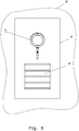
- the electrical / electronic installation device is designed as a door communication device.
- the electrical / electronic installation device can be assigned to the exterior or the interior of an entrance door, so be installed near the entrance door in the associated wall W of the building.
- the design cover 5 is provided at its, the wall W associated rear with an elastic seal D.
- the first functional module 3 has four actuating keys and is provided for activating the associated doorbell in each case in accordance with the requirements.
- the second functional module 4 contains a substantial part of the functional components of the door intercom, so it is usually equipped with a loudspeaker, microphone, electrical / electronic control components and so on. To complicate the possibility of actuating the second locking means 8 (detent springs) for unauthorized persons, they are covered by the design cover 5.
- a strap-like holding arrangement 12 is attached to the support assembly 2, which on the one hand serves to attach a tether, which on the other hand is fixed to the housing 1, whereby a secure holding possibility for removed from the housing 1 electrical / electronic installation device is realized.
- the tether is not shown.
Landscapes
- Engineering & Computer Science (AREA)
- Architecture (AREA)
- Civil Engineering (AREA)
- Structural Engineering (AREA)
- Casings For Electric Apparatus (AREA)
Claims (9)
- Appareil d'installation électrique/électronique, destiné à être monté de manière amovible dans un boîtier de montage (1) qui est fixé à demeure dans ou sur un bâtiment, l'appareil d'installation électrique/électronique présentant au moins une structure de support (2), un couvercle design (5), un insert de compensation (A) en forme de cadre, dont la profondeur de montage est réglable, et un module fonctionnel (3, 4) fixé sur une structure de support, le couvercle design (5) pouvant être fixé sur la structure de support (2) et la structure de support (2) étant prévue pour être fixée dans le boîtier de montage, l'insert de compensation (A) étant réalisé de façon à pouvoir être maintenu dans le boîtier de montage (1) de sorte que les parois extérieures de l'insert de compensation viennent s'appliquer contre les parois intérieures du boîtier de montage (1), l'insert de compensation (A) présentant quatre fentes (S) s'étendant dans la direction de montage pour la compensation du crépi, lesquelles coopèrent avec des vis de fixation (B) du boîtier de montage (1),
caractérisé en ce que
l'insert de compensation (A) présente au moins un premier moyen d'encliquetage (9) qui est adapté à coopérer par encliquetage avec un second moyen d'encliquetage (8) prévu sur la structure de support (2), le premier moyen encliquetage (9) et/ou le second moyen d'encliquetage (8) étant réalisé à la manière d'un ressort d'encliquetage. - Appareil d'installation électrique/électronique selon la revendication 1, caractérisé en ce qu'au moins un premier moyen d'encliquetage (9) et/ou un second moyen d'encliquetage (8) est réalisé à la manière d'une ouverture.
- Appareil d'installation électrique/électronique selon l'une des revendications 1 ou 2, caractérisé en ce qu'au moins un premier moyen d'encliquetage (9) et/ou un second moyen d'encliquetage (8) est réalisé à la manière d'un évidement.
- Appareil d'installation électrique/électronique selon l'une des revendications 1 à 3, caractérisé en ce qu'au moins un premier moyen d'encliquetage (9) et/ou un second moyen d'encliquetage (8) est réalisé à la manière d'un bec d'encliquetage.
- Appareil d'installation électrique/électronique selon l'une des revendications 1 à 4, caractérisé en ce qu'au moins deux premiers moyens d'encliquetage (9) sont présents sur l'insert de compensation (A).
- Appareil d'installation électrique/électronique selon l'une des revendications 1 à 5, caractérisé en ce qu'au moins deux seconds moyens d'encliquetage (8) sont présents sur la structure de support (2).
- Appareil d'installation électrique/électronique selon l'une des revendications 1 à 6, caractérisé en ce qu'au moins une base d'actionnement (6) prévue pour coopérer avec un outil de déverrouillage (10) est présente au moins sur un premier moyen d'encliquetage (9) et/ou un second moyen d'encliquetage (8).
- Appareil d'installation électrique/électronique selon l'une des revendications 1 à 7, caractérisé en ce que ledit au moins un premier moyen d'encliquetage (9) et que ledit au moins un second moyen d'encliquetage (8) sont cachés par le couvercle design (5).
- Appareil d'installation électrique/électronique selon l'une des revendications 1 à 8, caractérisé en ce qu'au moins un second moyen d'encliquetage (8) réalisé sous la forme d'un ressort d'encliquetage présente au moins une branche de retenue (7) coopérant par retenue avec un bord d'encliquetage (8a) de la structure de support (2) et au moins une branche d'encliquetage (8a) coopérant par encliquetage avec le premier moyen d'encliquetage (9) de l'insert de compensation (A).
Priority Applications (1)
| Application Number | Priority Date | Filing Date | Title |
|---|---|---|---|
| PL14165106T PL2852016T3 (pl) | 2013-09-23 | 2014-04-17 | Elektryczne/elektroniczne urządzenie instalacyjne |
Applications Claiming Priority (1)
| Application Number | Priority Date | Filing Date | Title |
|---|---|---|---|
| DE102013110460.6A DE102013110460B3 (de) | 2013-09-23 | 2013-09-23 | Elektrisches/elektronisches Installationsgerät |
Publications (3)
| Publication Number | Publication Date |
|---|---|
| EP2852016A2 EP2852016A2 (fr) | 2015-03-25 |
| EP2852016A3 EP2852016A3 (fr) | 2015-06-03 |
| EP2852016B1 true EP2852016B1 (fr) | 2019-02-13 |
Family
ID=50488999
Family Applications (1)
| Application Number | Title | Priority Date | Filing Date |
|---|---|---|---|
| EP14165106.7A Active EP2852016B1 (fr) | 2013-09-23 | 2014-04-17 | Appareil d'installation électrique/électronique |
Country Status (4)
| Country | Link |
|---|---|
| EP (1) | EP2852016B1 (fr) |
| DE (1) | DE102013110460B3 (fr) |
| ES (1) | ES2725882T3 (fr) |
| PL (1) | PL2852016T3 (fr) |
Families Citing this family (1)
| Publication number | Priority date | Publication date | Assignee | Title |
|---|---|---|---|---|
| DE102014220307B3 (de) | 2014-10-07 | 2016-01-07 | Berker Gmbh & Co. Kg | Befestigungsvorrichtung zum Festlegen einer Trägeranordnung einer Türkommunikationseinrichtung in einem Einbaugehäuse |
Citations (4)
| Publication number | Priority date | Publication date | Assignee | Title |
|---|---|---|---|---|
| DE7038846U (de) * | 1970-10-21 | 1971-03-18 | Rittal-Werk R Loh Kg | Unterputzkasten, insbesondere fur Sprechanlagen |
| CH585472A5 (fr) * | 1975-09-08 | 1977-02-28 | Feller Ag Adolf | |
| DE10229930A1 (de) * | 2002-07-04 | 2004-01-29 | Lic Langmatz Gmbh | Leergehäuse zur Unterbringung eines Hausanschlußkastens |
| EP2552085A2 (fr) * | 2011-07-27 | 2013-01-30 | Abb Ag | Système de montage d'une station, notamment d'une station de porte, d'un système de communication domestique |
Family Cites Families (8)
| Publication number | Priority date | Publication date | Assignee | Title |
|---|---|---|---|---|
| AT206963B (de) * | 1957-10-24 | 1960-01-11 | Busch Jaeger Duerener Metall | Unterputzdose mit eingesetzter Tragvorrichtung für mehrere Installationsgeräte |
| DE19525527C2 (de) * | 1995-07-13 | 1997-11-20 | Golos Selvin | Vorrichtung zum Befestigen von Installationsgeräten in einer Unterputzdose |
| DE19632536C2 (de) * | 1996-08-13 | 1999-05-27 | Maier & Cie C | Vorrichtung zum Befestigen eines Einbaugerätes, insbesondere einer Steckdose |
| US5823821A (en) * | 1997-03-31 | 1998-10-20 | Tohanczyn, Jr.; Edward | Apparatus for securing an electrical outlet to an outlet box having stripped threads |
| US5913439A (en) * | 1997-08-29 | 1999-06-22 | Watlow Electric Manufacturing Co. | Mounting assembly with dual mount collar |
| EP1241741A1 (fr) * | 2001-03-13 | 2002-09-18 | GIRA GIERSIEPEN GmbH. & CO. KG | Appareil électrique, spécialement multiprise, pour le montage dans une ouverture d'un conduit de câble |
| DE102010016345B4 (de) * | 2010-04-07 | 2011-11-24 | Berker Gmbh & Co. Kg | Steuergerät für ein Gebäudeinstallationssystem |
| EP2602888B1 (fr) * | 2011-12-09 | 2015-11-25 | Schneider Electric Industries SAS | Verrouillage libérable avec capacité d'ajustement d'angle |
-
2013
- 2013-09-23 DE DE102013110460.6A patent/DE102013110460B3/de not_active Expired - Fee Related
-
2014
- 2014-04-17 ES ES14165106T patent/ES2725882T3/es active Active
- 2014-04-17 PL PL14165106T patent/PL2852016T3/pl unknown
- 2014-04-17 EP EP14165106.7A patent/EP2852016B1/fr active Active
Patent Citations (4)
| Publication number | Priority date | Publication date | Assignee | Title |
|---|---|---|---|---|
| DE7038846U (de) * | 1970-10-21 | 1971-03-18 | Rittal-Werk R Loh Kg | Unterputzkasten, insbesondere fur Sprechanlagen |
| CH585472A5 (fr) * | 1975-09-08 | 1977-02-28 | Feller Ag Adolf | |
| DE10229930A1 (de) * | 2002-07-04 | 2004-01-29 | Lic Langmatz Gmbh | Leergehäuse zur Unterbringung eines Hausanschlußkastens |
| EP2552085A2 (fr) * | 2011-07-27 | 2013-01-30 | Abb Ag | Système de montage d'une station, notamment d'une station de porte, d'un système de communication domestique |
Also Published As
| Publication number | Publication date |
|---|---|
| DE102013110460B3 (de) | 2014-07-31 |
| EP2852016A2 (fr) | 2015-03-25 |
| ES2725882T3 (es) | 2019-09-30 |
| EP2852016A3 (fr) | 2015-06-03 |
| PL2852016T3 (pl) | 2019-08-30 |
Similar Documents
| Publication | Publication Date | Title |
|---|---|---|
| EP3873768A1 (fr) | Dispositif de charge pour véhicules électriques | |
| DE102009043455A1 (de) | Anordnung zum Installieren von Geräten der Gebäudesystemtechnik | |
| EP2852016B1 (fr) | Appareil d'installation électrique/électronique | |
| DE102012101609A1 (de) | Montagemodul für die Wandmontage eines Anzeigeelementes | |
| DE102011000448A1 (de) | Installationsgerät für ein elektrisches Installationssystem | |
| DE102013104259B3 (de) | Elektrisches/elektronisches Installationsgerät | |
| EP2930809B1 (fr) | Appareil d'installation électrique/électronique | |
| DE102017006870A1 (de) | Elektrisches Installationsgerät | |
| EP2453541B1 (fr) | Agencement de commutateurs électriques | |
| EP2348598B1 (fr) | Appareil d'installation encastré électrique pour un appareil audio mobile | |
| DE102007045869B3 (de) | Elektrisches/elektronisches Installationsgerät | |
| DE102013110461A1 (de) | Elektrisches/elektronisches Installationsgerät | |
| DE102014220307B3 (de) | Befestigungsvorrichtung zum Festlegen einer Trägeranordnung einer Türkommunikationseinrichtung in einem Einbaugehäuse | |
| DE102014110652B3 (de) | Elektrisches/elektronisches Installationsgerät | |
| DE102013105893B3 (de) | Elektrisches/elektronisches Installationsgerät | |
| EP3503309B1 (fr) | Appareil d'installation électrique/électronique | |
| EP2351176B1 (fr) | Boîte d'installation électrique | |
| DE202017104726U1 (de) | Elektrisches Installationsgerät | |
| EP3503310B1 (fr) | Appareil d'installation électrique/électronique | |
| EP2930808A1 (fr) | Appareil d'installation électrique ou électronique | |
| DE102023200638B3 (de) | Zubehör für einen elektrischen Schalter und elektrischer Schalter mit solch einem Zubehör | |
| DE202014004926U1 (de) | Anlagenmodul mit Befestigungen | |
| EP2811599B1 (fr) | Appareil d'installation électrique/électronique | |
| DE102012100602A1 (de) | Aufnahmevorrichtung für Tablet-Computer | |
| CH695715A5 (de) | Apparat für elektrische Hausinstallationen. |
Legal Events
| Date | Code | Title | Description |
|---|---|---|---|
| PUAI | Public reference made under article 153(3) epc to a published international application that has entered the european phase |
Free format text: ORIGINAL CODE: 0009012 |
|
| 17P | Request for examination filed |
Effective date: 20140417 |
|
| AK | Designated contracting states |
Kind code of ref document: A2 Designated state(s): AL AT BE BG CH CY CZ DE DK EE ES FI FR GB GR HR HU IE IS IT LI LT LU LV MC MK MT NL NO PL PT RO RS SE SI SK SM TR |
|
| AX | Request for extension of the european patent |
Extension state: BA ME |
|
| PUAL | Search report despatched |
Free format text: ORIGINAL CODE: 0009013 |
|
| AK | Designated contracting states |
Kind code of ref document: A3 Designated state(s): AL AT BE BG CH CY CZ DE DK EE ES FI FR GB GR HR HU IE IS IT LI LT LU LV MC MK MT NL NO PL PT RO RS SE SI SK SM TR |
|
| AX | Request for extension of the european patent |
Extension state: BA ME |
|
| RIC1 | Information provided on ipc code assigned before grant |
Ipc: H02G 3/12 20060101ALI20150428BHEP Ipc: H02G 3/08 20060101AFI20150428BHEP |
|
| R17P | Request for examination filed (corrected) |
Effective date: 20151203 |
|
| RBV | Designated contracting states (corrected) |
Designated state(s): AL AT BE BG CH CY CZ DE DK EE ES FI FR GB GR HR HU IE IS IT LI LT LU LV MC MK MT NL NO PL PT RO RS SE SI SK SM TR |
|
| STAA | Information on the status of an ep patent application or granted ep patent |
Free format text: STATUS: EXAMINATION IS IN PROGRESS |
|
| 17Q | First examination report despatched |
Effective date: 20170526 |
|
| GRAP | Despatch of communication of intention to grant a patent |
Free format text: ORIGINAL CODE: EPIDOSNIGR1 |
|
| STAA | Information on the status of an ep patent application or granted ep patent |
Free format text: STATUS: GRANT OF PATENT IS INTENDED |
|
| INTG | Intention to grant announced |
Effective date: 20180903 |
|
| GRAS | Grant fee paid |
Free format text: ORIGINAL CODE: EPIDOSNIGR3 |
|
| GRAA | (expected) grant |
Free format text: ORIGINAL CODE: 0009210 |
|
| STAA | Information on the status of an ep patent application or granted ep patent |
Free format text: STATUS: THE PATENT HAS BEEN GRANTED |
|
| AK | Designated contracting states |
Kind code of ref document: B1 Designated state(s): AL AT BE BG CH CY CZ DE DK EE ES FI FR GB GR HR HU IE IS IT LI LT LU LV MC MK MT NL NO PL PT RO RS SE SI SK SM TR |
|
| REG | Reference to a national code |
Ref country code: GB Ref legal event code: FG4D Free format text: NOT ENGLISH |
|
| REG | Reference to a national code |
Ref country code: CH Ref legal event code: EP Ref country code: AT Ref legal event code: REF Ref document number: 1096745 Country of ref document: AT Kind code of ref document: T Effective date: 20190215 |
|
| REG | Reference to a national code |
Ref country code: IE Ref legal event code: FG4D Free format text: LANGUAGE OF EP DOCUMENT: GERMAN |
|
| REG | Reference to a national code |
Ref country code: DE Ref legal event code: R096 Ref document number: 502014010788 Country of ref document: DE |
|
| REG | Reference to a national code |
Ref country code: LT Ref legal event code: MG4D |
|
| REG | Reference to a national code |
Ref country code: NL Ref legal event code: MP Effective date: 20190213 |
|
| PG25 | Lapsed in a contracting state [announced via postgrant information from national office to epo] |
Ref country code: FI Free format text: LAPSE BECAUSE OF FAILURE TO SUBMIT A TRANSLATION OF THE DESCRIPTION OR TO PAY THE FEE WITHIN THE PRESCRIBED TIME-LIMIT Effective date: 20190213 Ref country code: LT Free format text: LAPSE BECAUSE OF FAILURE TO SUBMIT A TRANSLATION OF THE DESCRIPTION OR TO PAY THE FEE WITHIN THE PRESCRIBED TIME-LIMIT Effective date: 20190213 Ref country code: NL Free format text: LAPSE BECAUSE OF FAILURE TO SUBMIT A TRANSLATION OF THE DESCRIPTION OR TO PAY THE FEE WITHIN THE PRESCRIBED TIME-LIMIT Effective date: 20190213 Ref country code: SE Free format text: LAPSE BECAUSE OF FAILURE TO SUBMIT A TRANSLATION OF THE DESCRIPTION OR TO PAY THE FEE WITHIN THE PRESCRIBED TIME-LIMIT Effective date: 20190213 Ref country code: PT Free format text: LAPSE BECAUSE OF FAILURE TO SUBMIT A TRANSLATION OF THE DESCRIPTION OR TO PAY THE FEE WITHIN THE PRESCRIBED TIME-LIMIT Effective date: 20190613 Ref country code: NO Free format text: LAPSE BECAUSE OF FAILURE TO SUBMIT A TRANSLATION OF THE DESCRIPTION OR TO PAY THE FEE WITHIN THE PRESCRIBED TIME-LIMIT Effective date: 20190513 |
|
| PG25 | Lapsed in a contracting state [announced via postgrant information from national office to epo] |
Ref country code: RS Free format text: LAPSE BECAUSE OF FAILURE TO SUBMIT A TRANSLATION OF THE DESCRIPTION OR TO PAY THE FEE WITHIN THE PRESCRIBED TIME-LIMIT Effective date: 20190213 Ref country code: GR Free format text: LAPSE BECAUSE OF FAILURE TO SUBMIT A TRANSLATION OF THE DESCRIPTION OR TO PAY THE FEE WITHIN THE PRESCRIBED TIME-LIMIT Effective date: 20190514 Ref country code: LV Free format text: LAPSE BECAUSE OF FAILURE TO SUBMIT A TRANSLATION OF THE DESCRIPTION OR TO PAY THE FEE WITHIN THE PRESCRIBED TIME-LIMIT Effective date: 20190213 Ref country code: HR Free format text: LAPSE BECAUSE OF FAILURE TO SUBMIT A TRANSLATION OF THE DESCRIPTION OR TO PAY THE FEE WITHIN THE PRESCRIBED TIME-LIMIT Effective date: 20190213 Ref country code: IS Free format text: LAPSE BECAUSE OF FAILURE TO SUBMIT A TRANSLATION OF THE DESCRIPTION OR TO PAY THE FEE WITHIN THE PRESCRIBED TIME-LIMIT Effective date: 20190613 Ref country code: BG Free format text: LAPSE BECAUSE OF FAILURE TO SUBMIT A TRANSLATION OF THE DESCRIPTION OR TO PAY THE FEE WITHIN THE PRESCRIBED TIME-LIMIT Effective date: 20190513 |
|
| REG | Reference to a national code |
Ref country code: ES Ref legal event code: FG2A Ref document number: 2725882 Country of ref document: ES Kind code of ref document: T3 Effective date: 20190930 |
|
| PG25 | Lapsed in a contracting state [announced via postgrant information from national office to epo] |
Ref country code: EE Free format text: LAPSE BECAUSE OF FAILURE TO SUBMIT A TRANSLATION OF THE DESCRIPTION OR TO PAY THE FEE WITHIN THE PRESCRIBED TIME-LIMIT Effective date: 20190213 Ref country code: CZ Free format text: LAPSE BECAUSE OF FAILURE TO SUBMIT A TRANSLATION OF THE DESCRIPTION OR TO PAY THE FEE WITHIN THE PRESCRIBED TIME-LIMIT Effective date: 20190213 Ref country code: RO Free format text: LAPSE BECAUSE OF FAILURE TO SUBMIT A TRANSLATION OF THE DESCRIPTION OR TO PAY THE FEE WITHIN THE PRESCRIBED TIME-LIMIT Effective date: 20190213 Ref country code: DK Free format text: LAPSE BECAUSE OF FAILURE TO SUBMIT A TRANSLATION OF THE DESCRIPTION OR TO PAY THE FEE WITHIN THE PRESCRIBED TIME-LIMIT Effective date: 20190213 Ref country code: SK Free format text: LAPSE BECAUSE OF FAILURE TO SUBMIT A TRANSLATION OF THE DESCRIPTION OR TO PAY THE FEE WITHIN THE PRESCRIBED TIME-LIMIT Effective date: 20190213 Ref country code: AL Free format text: LAPSE BECAUSE OF FAILURE TO SUBMIT A TRANSLATION OF THE DESCRIPTION OR TO PAY THE FEE WITHIN THE PRESCRIBED TIME-LIMIT Effective date: 20190213 |
|
| REG | Reference to a national code |
Ref country code: DE Ref legal event code: R097 Ref document number: 502014010788 Country of ref document: DE |
|
| PG25 | Lapsed in a contracting state [announced via postgrant information from national office to epo] |
Ref country code: SM Free format text: LAPSE BECAUSE OF FAILURE TO SUBMIT A TRANSLATION OF THE DESCRIPTION OR TO PAY THE FEE WITHIN THE PRESCRIBED TIME-LIMIT Effective date: 20190213 |
|
| REG | Reference to a national code |
Ref country code: CH Ref legal event code: PL |
|
| PLBE | No opposition filed within time limit |
Free format text: ORIGINAL CODE: 0009261 |
|
| STAA | Information on the status of an ep patent application or granted ep patent |
Free format text: STATUS: NO OPPOSITION FILED WITHIN TIME LIMIT |
|
| PG25 | Lapsed in a contracting state [announced via postgrant information from national office to epo] |
Ref country code: LU Free format text: LAPSE BECAUSE OF NON-PAYMENT OF DUE FEES Effective date: 20190417 Ref country code: MC Free format text: LAPSE BECAUSE OF FAILURE TO SUBMIT A TRANSLATION OF THE DESCRIPTION OR TO PAY THE FEE WITHIN THE PRESCRIBED TIME-LIMIT Effective date: 20190213 |
|
| 26N | No opposition filed |
Effective date: 20191114 |
|
| PG25 | Lapsed in a contracting state [announced via postgrant information from national office to epo] |
Ref country code: LI Free format text: LAPSE BECAUSE OF NON-PAYMENT OF DUE FEES Effective date: 20190430 Ref country code: CH Free format text: LAPSE BECAUSE OF NON-PAYMENT OF DUE FEES Effective date: 20190430 |
|
| PG25 | Lapsed in a contracting state [announced via postgrant information from national office to epo] |
Ref country code: SI Free format text: LAPSE BECAUSE OF FAILURE TO SUBMIT A TRANSLATION OF THE DESCRIPTION OR TO PAY THE FEE WITHIN THE PRESCRIBED TIME-LIMIT Effective date: 20190213 |
|
| PG25 | Lapsed in a contracting state [announced via postgrant information from national office to epo] |
Ref country code: TR Free format text: LAPSE BECAUSE OF FAILURE TO SUBMIT A TRANSLATION OF THE DESCRIPTION OR TO PAY THE FEE WITHIN THE PRESCRIBED TIME-LIMIT Effective date: 20190213 |
|
| PG25 | Lapsed in a contracting state [announced via postgrant information from national office to epo] |
Ref country code: IE Free format text: LAPSE BECAUSE OF NON-PAYMENT OF DUE FEES Effective date: 20190417 |
|
| PG25 | Lapsed in a contracting state [announced via postgrant information from national office to epo] |
Ref country code: CY Free format text: LAPSE BECAUSE OF FAILURE TO SUBMIT A TRANSLATION OF THE DESCRIPTION OR TO PAY THE FEE WITHIN THE PRESCRIBED TIME-LIMIT Effective date: 20190213 |
|
| PG25 | Lapsed in a contracting state [announced via postgrant information from national office to epo] |
Ref country code: HU Free format text: LAPSE BECAUSE OF FAILURE TO SUBMIT A TRANSLATION OF THE DESCRIPTION OR TO PAY THE FEE WITHIN THE PRESCRIBED TIME-LIMIT; INVALID AB INITIO Effective date: 20140417 Ref country code: MT Free format text: LAPSE BECAUSE OF FAILURE TO SUBMIT A TRANSLATION OF THE DESCRIPTION OR TO PAY THE FEE WITHIN THE PRESCRIBED TIME-LIMIT Effective date: 20190213 |
|
| PG25 | Lapsed in a contracting state [announced via postgrant information from national office to epo] |
Ref country code: MK Free format text: LAPSE BECAUSE OF FAILURE TO SUBMIT A TRANSLATION OF THE DESCRIPTION OR TO PAY THE FEE WITHIN THE PRESCRIBED TIME-LIMIT Effective date: 20190213 |
|
| P01 | Opt-out of the competence of the unified patent court (upc) registered |
Effective date: 20230606 |
|
| PGFP | Annual fee paid to national office [announced via postgrant information from national office to epo] |
Ref country code: PL Payment date: 20250401 Year of fee payment: 12 Ref country code: DE Payment date: 20250429 Year of fee payment: 12 |
|
| PGFP | Annual fee paid to national office [announced via postgrant information from national office to epo] |
Ref country code: GB Payment date: 20250428 Year of fee payment: 12 Ref country code: ES Payment date: 20250505 Year of fee payment: 12 |
|
| PGFP | Annual fee paid to national office [announced via postgrant information from national office to epo] |
Ref country code: IT Payment date: 20250422 Year of fee payment: 12 Ref country code: BE Payment date: 20250428 Year of fee payment: 12 |
|
| PGFP | Annual fee paid to national office [announced via postgrant information from national office to epo] |
Ref country code: FR Payment date: 20250425 Year of fee payment: 12 |
|
| PGFP | Annual fee paid to national office [announced via postgrant information from national office to epo] |
Ref country code: AT Payment date: 20250402 Year of fee payment: 12 |