EP2852012A1 - Dispositif à effet laser - Google Patents
Dispositif à effet laser Download PDFInfo
- Publication number
- EP2852012A1 EP2852012A1 EP13791219.2A EP13791219A EP2852012A1 EP 2852012 A1 EP2852012 A1 EP 2852012A1 EP 13791219 A EP13791219 A EP 13791219A EP 2852012 A1 EP2852012 A1 EP 2852012A1
- Authority
- EP
- European Patent Office
- Prior art keywords
- gas
- laser medium
- lasing device
- time
- supply valve
- Prior art date
- Legal status (The legal status is an assumption and is not a legal conclusion. Google has not performed a legal analysis and makes no representation as to the accuracy of the status listed.)
- Granted
Links
Images


Classifications
-
- H—ELECTRICITY
- H01—ELECTRIC ELEMENTS
- H01S—DEVICES USING THE PROCESS OF LIGHT AMPLIFICATION BY STIMULATED EMISSION OF RADIATION [LASER] TO AMPLIFY OR GENERATE LIGHT; DEVICES USING STIMULATED EMISSION OF ELECTROMAGNETIC RADIATION IN WAVE RANGES OTHER THAN OPTICAL
- H01S3/00—Lasers, i.e. devices using stimulated emission of electromagnetic radiation in the infrared, visible or ultraviolet wave range
- H01S3/02—Constructional details
- H01S3/03—Constructional details of gas laser discharge tubes
- H01S3/036—Means for obtaining or maintaining the desired gas pressure within the tube, e.g. by gettering, replenishing; Means for circulating the gas, e.g. for equalising the pressure within the tube
-
- H—ELECTRICITY
- H01—ELECTRIC ELEMENTS
- H01S—DEVICES USING THE PROCESS OF LIGHT AMPLIFICATION BY STIMULATED EMISSION OF RADIATION [LASER] TO AMPLIFY OR GENERATE LIGHT; DEVICES USING STIMULATED EMISSION OF ELECTROMAGNETIC RADIATION IN WAVE RANGES OTHER THAN OPTICAL
- H01S3/00—Lasers, i.e. devices using stimulated emission of electromagnetic radiation in the infrared, visible or ultraviolet wave range
- H01S3/10—Controlling the intensity, frequency, phase, polarisation or direction of the emitted radiation, e.g. switching, gating, modulating or demodulating
- H01S3/13—Stabilisation of laser output parameters, e.g. frequency or amplitude
- H01S3/131—Stabilisation of laser output parameters, e.g. frequency or amplitude by controlling the active medium, e.g. by controlling the processes or apparatus for excitation
- H01S3/134—Stabilisation of laser output parameters, e.g. frequency or amplitude by controlling the active medium, e.g. by controlling the processes or apparatus for excitation in gas lasers
-
- H—ELECTRICITY
- H01—ELECTRIC ELEMENTS
- H01S—DEVICES USING THE PROCESS OF LIGHT AMPLIFICATION BY STIMULATED EMISSION OF RADIATION [LASER] TO AMPLIFY OR GENERATE LIGHT; DEVICES USING STIMULATED EMISSION OF ELECTROMAGNETIC RADIATION IN WAVE RANGES OTHER THAN OPTICAL
- H01S3/00—Lasers, i.e. devices using stimulated emission of electromagnetic radiation in the infrared, visible or ultraviolet wave range
- H01S3/10—Controlling the intensity, frequency, phase, polarisation or direction of the emitted radiation, e.g. switching, gating, modulating or demodulating
- H01S3/10069—Memorized or pre-programmed characteristics, e.g. look-up table [LUT]
-
- H—ELECTRICITY
- H01—ELECTRIC ELEMENTS
- H01S—DEVICES USING THE PROCESS OF LIGHT AMPLIFICATION BY STIMULATED EMISSION OF RADIATION [LASER] TO AMPLIFY OR GENERATE LIGHT; DEVICES USING STIMULATED EMISSION OF ELECTROMAGNETIC RADIATION IN WAVE RANGES OTHER THAN OPTICAL
- H01S3/00—Lasers, i.e. devices using stimulated emission of electromagnetic radiation in the infrared, visible or ultraviolet wave range
- H01S3/10—Controlling the intensity, frequency, phase, polarisation or direction of the emitted radiation, e.g. switching, gating, modulating or demodulating
- H01S3/102—Controlling the intensity, frequency, phase, polarisation or direction of the emitted radiation, e.g. switching, gating, modulating or demodulating by controlling the active medium, e.g. by controlling the processes or apparatus for excitation
- H01S3/104—Controlling the intensity, frequency, phase, polarisation or direction of the emitted radiation, e.g. switching, gating, modulating or demodulating by controlling the active medium, e.g. by controlling the processes or apparatus for excitation in gas lasers
-
- H—ELECTRICITY
- H01—ELECTRIC ELEMENTS
- H01S—DEVICES USING THE PROCESS OF LIGHT AMPLIFICATION BY STIMULATED EMISSION OF RADIATION [LASER] TO AMPLIFY OR GENERATE LIGHT; DEVICES USING STIMULATED EMISSION OF ELECTROMAGNETIC RADIATION IN WAVE RANGES OTHER THAN OPTICAL
- H01S3/00—Lasers, i.e. devices using stimulated emission of electromagnetic radiation in the infrared, visible or ultraviolet wave range
- H01S3/14—Lasers, i.e. devices using stimulated emission of electromagnetic radiation in the infrared, visible or ultraviolet wave range characterised by the material used as the active medium
- H01S3/22—Gases
- H01S3/223—Gases the active gas being polyatomic, i.e. containing two or more atoms
- H01S3/2232—Carbon dioxide (CO2) or monoxide [CO]
Definitions
- the present invention relates to a lasing device using laser medium gas.
- Lasing devices can process a workpiece with no contact and minimized thermal adverse effect.
- the advantages allow the devices to be in heavily usage: cutting various materials into various shapes, welding, and processing.
- a CO 2 -gas lasing device which employs CO 2 -based mixed gas as laser medium gas, has been widely used because of its excellent laser-beam characteristics and relatively easily obtained significant output.
- Such a gas lasing device has an optical resonator and a gas circulation path connected to the optical resonator.
- Laser medium gas which is heated by discharge excitation in the optical resonator, is cooled down while circulating through the gas circulation path.
- the gas circulation path has a blower for circulating the laser medium gas.
- a gas canister filled with a mixed gas in advance is employed as a laser medium gas supply device.
- a piping structural member made of resin or metal is used for piping for connecting between the gas canister and a gas supply valve of the lasing device.
- a piping structural member has a tiny pin hole, for example, in a CO 2 -gas lasing device, helium (He) included in the mixed gas can selectively escape through the pin hole. The leakage can cause change in the mixture ratio of the laser medium gas retaining in the piping between the gas canister and the gas supply valve of the lasing device, by which stable laser output cannot be obtained.
- Fig. 7 shows a conventional lasing device.
- Fig. 7 shows a piping system of a laser gas supply system for supplying gas to gas line 910 of a laser gas circulation system of the gas lasing device.
- the laser gas is supplied to gas line 910 via primary pressure regulator 915, piping 916, filter 917, pressure regulator 918, valve 919, valve 920, quick supply flowmeter 921, and normal supply flowmeter 922.
- the pressure in gas line 910 is measured by pressure sensor 923.
- the gas in gas line 910 is released by vacuum pump 924 via quick release valve 925 or normal release valve 926.
- release valve 927 and timer 928 the laser medium gas retaining in piping 916 between gas canister 914 and gas line 910 is released outside at the start up of the gas lasing device.
- Fig. 8 shows an open/close sequence of each valve of the conventional gas lasing device.
- release valve 927 is maintained open while the gas retaining in the lasing device is being released (i.e., while valves 925 and 926 are both maintained open).
- the laser medium gas retaining in piping 916 is released outside at the start up of the device for providing laser output with stability (see patent literature 1, for example).
- the conventional lasing device needs dedicated release valve 927.
- the open time of release valve 927 is determined to a maximum time for releasing gas corresponding to the volume of piping 916 connecting between gas canister 914 and the lasing device. Therefore, when the lasing device has a short stop time, the laser medium gas has been released more than necessary.
- the present invention provides a lasing device not only capable of decreasing cost by using decreased number of valves, but also capable of suppressing consumption of laser medium gas.
- the lasing device of the present invention supplies laser medium gas from outside continuously or intermittently.
- the lasing device of the present invention has an optical resonator, a gas circulation path, a laser medium gas supply device, a gas release pump, a gas pressure detector, a gas pressure controller, a blower, a current detector, a stop-time counter, a storage, and an open-time calculator.
- the gas circulation path is connected to the optical resonator.
- the laser medium gas supply device supplies the gas circulation path or the optical resonator with laser medium gas via a gas supply valve.
- the gas release pump releases the laser medium gas from the gas circulation path or the optical resonator via a gas release valve.
- the gas pressure detector detects the gas pressure of the laser medium gas in the gas circulation path or the optical resonator. In response to the gas pressure detected by the gas pressure detector, the gas pressure controller controls the gas supply valve and the gas release valve.
- the blower is disposed in the gas circulation path.
- the current detector detects blower driving current of the blower.
- the stop-time counter measures the stop time of the lasing device.
- the storage stores correlated information between the stop time and blower driving current. In response to the information from the storage, the open-time calculator calculates the open time of the gas supply valve at the start up of the lasing device.
- the gas retaining in the gas circulation path and the optical resonator is released through the gas release valve opened by the gas pressure controller.
- laser medium gas in the piping between the laser medium gas supply device and the gas supply valve is released, together with retaining gas, through the gas supply valve opened by the gas pressure controller.
- the retaining gas is released-by only a required amount of it-outside the lasing device, even if the mixture ratio of the laser medium gas (retaining in the piping between the gas canister and the gas supply valve of the lasing device) varies in the stop time of the lasing device.
- the structure decreases the number of valves used for the device, and accordingly, achieves cost reduction. Further, the structure suppresses consumption of laser medium gas.
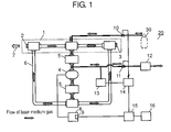
- optical resonator 1 is formed of half mirror 2 and total reflecting mirror 3 disposed so as to face half mirror 2.
- Gas circulation path 6 is connected to optical resonator 1, and they form a laser medium gas passage.
- Blower 4 whose rotation is controlled at a predetermined number of rotations by inverter 8, circulates laser medium gas through the laser medium gas passage.
- the driving current for blower 4 is detected by current detector 9 that is disposed in inverter 8.
- a high-voltage supply (not shown) produces discharge excitation in optical resonator 1, and blower 4 provides the laser medium gas with compression for circulating, which increases the temperature of the laser medium gas.
- Heat exchangers 5 cool down the laser medium gas circulating through the laser medium gas passage to protect optical resonator 1 from having an excessive high temperature.
- One of heat exchangers 5 is located on the side of the downstream of laser-medium-gas flow (hereinafter, referred to as the downstream side) of optical resonator 1 and is located on the side of the upstream of the laser-medium-gas flow (hereinafter, referred to as the upstream side) of blower 4.
- the other one of heat exchangers 5 is located on the downstream side of blower 4. Such positioned heat exchangers quickly cool down the heated laser medium gas.
- Gas canister 30 supplies the laser medium gas to the laser medium gas passage (formed of optical resonator 1 and gas circulation path 6) via gas supply valve 10.
- Gas canister 30, which is a laser medium gas supply device, is disposed outside lasing device 20.
- gas supply valve 10 is connected to optical resonator 1.
- the laser medium gas circulates through the laser medium gas passage formed of optical resonator 1 and gas circulation path 6 and is released outside the laser medium gas passage by vacuum pump 12 via gas release valve 11.
- gas release valve 11 is connected to gas circulation path 6 on the upstream side of blower 4 in the structure, it is not limited to. Gas release valve 11 may be disposed in some other place in gas circulation path 6.
- Gas supply valve 10 and gas release valve 11 are made of a solenoid valve.
- Gas pressure controller 14 (that will be described later) performs open/close control of them.
- the laser medium gas in optical resonator 1 needs to be controlled at an optimum gas pressure for offering constant intensity of laser beam 7.
- gas pressure detector 13 detects the gas pressure of the laser medium gas circulating through the laser medium gas passage formed of optical resonator 1 and gas circulation path 6. Further, gas pressure detector 13 outputs a gas pressure signal, which is an electric signal proportional to the detected gas pressure, to gas pressure controller 14.
- gas pressure detector 13 is connected between gas circulation path 6 and gas release valve 11, but it is not limited to. Gas pressure detector 13 may be connected to gas circulation path 6 or optical resonator 1.
- Gas pressure controller 14 carries out open/close control of gas supply valve 10 and gas release valve 11 so that the laser medium gas in optical resonator 1 has a predetermined gas pressure.
- the load on blower 4 increases in proportion to the density of the laser medium gas.
- the increase in load on blower 4 increases blower driving current fed from inverter 8.
- the blower driving current is detected by built-in current detector 9 of inverter 8.
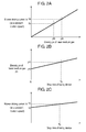
- blower driving current Ix increases in proportion to density px of laser medium gas.
- Blower driving current Ix is represented by expression (1)
- gas canister 30 i.e., the laser medium gas supply device
- gas supply valve 10 has a tiny pin hole
- helium (He) included in the mixed gas can selectively escape through the pin hole.
- the leakage causes change in the mixture ratio of the laser medium gas retaining in the piping between gas canister 30 and gas supply valve 10 of the lasing device.
- the mixture ratio of the retaining gas keeps changing during the stop time of the device.
- density px of the laser medium gas retaining in the lasing device increases in proportion to the stop time of the device.
- the graph of Fig. 2C is obtained in a manner that each relation of valuables shown in Fig. 2A and Fig. 2B are integrated and then replaced with relation of driving current Ix' for blower 4 with respect to the stop time of the lasing device.
- the graph of Fig. 2C shows that driving current Ix' for blower 4, too, increases with the passage of the stop time of the device.
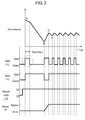
- the gas pressure has the level shown by A in the graph.
- vacuum pump 12 turns on, and then gas release valve 11 and gas supply valve 10 open.
- gas release valve 11 the laser medium gas is released from gas circulation path 6 and optical resonator 1 by vacuum pump 12.
- gas supply valve 10 fresh laser medium gas from gas canister 30 is fed, together with the laser medium gas retaining in the piping between gas canister 30 and gas supply valve 10, into gas circulation path 6 and optical resonator 1.
- the laser medium gas retaining in the piping is fed into lasing device 20 but quickly released from the device by vacuum pump 12.
- gas supply valve 10 becomes open regularly until the gas pressure lowers to the level of B, the open timing of gas supply valve 10 is not necessarily synchronized with that of gas release valve 11.
- gas supply valve 10 After gas supply valve 10 is closed, the gas pressure goes down to level B. When the gas pressure reaches level B, gas release valve 11 is closed, whereas gas supply valve 10 is open and laser medium gas is fed to gas circulation path 6 and optical resonator 1 therethrough. Further, inverter 8 turns on and blower 4 starts rotating.
- gas pressure controller 14 carries out open/close control of gas supply valve 10 and gas release valve 11 so that the gas pressure is maintained at a level between C and D in response to the detected value by gas pressure detector 13.
- blower 4 reaches a predetermined speed around the time at which the increasing gas pressure reaches level C, and after that, blower 4 is controlled at a constant speed.
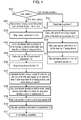
- Fig. 4 is a flow chart of the workings-mainly illustrating the procedures of initial setting-of the lasing device of the exemplary embodiment.
- Each graph of Fig. 5 and Fig. 6 illustrates the principle of calculation in the initial setting.
- Lasing device 20 is placed in an intended working environment and the piping between gas canister 30 and lasing device 20 is installed. After that, the initial setting for calculation of the open time of gas supply valve 10 is carried out.
- Step S01 of Fig. 3 is for determining whether the initial setting is performed or not.
- step S02 is performed.
- step S02 the laser medium gas retaining in gas circulation path 6, optical resonator 1, and the piping between gas canister 30 and lasing device 20 is completely released.
- current detector 9 detects blower driving current under the normal condition of the gas mixture ratio. The detected current value is stored as driving current Id in the storage mounted on open-time calculator 15.
- Driving current Id is the same as that shown in the graph of Fig. 2C .
- step S03 the lasing device is stopped and maintained in the stop state for predetermined stop time Tc.
- Stop time Tc is counted by stop-time counter 16 and stored in the storage mounted on open-time calculator 15. Stop time Tc is the same as that shown in the graph of Fig. 2C . Stop time Tc can be arbitrarily determined as long as its length is enough for detecting difference in blower driving current (that will be described later).
- step S04 the lasing device is turned on in step S04.
- current detector 9 detects the blower driving current when blower 4 is controlled at a constant speed.
- the detected current value is stored as driving current Ic in the storage mounted on open-time calculator 15.
- Driving current Ic is the same as that shown in the graph of Fig. 2C .
- step S03 until the gas pressure decreases to level B from level A in response to the start up of the lasing device, gas supply valve 10 is maintained to be closed.
- open-time calculator 15 calculates gradient ⁇ from expression (4) described earlier.
- Gradient ⁇ represents correlation of the blower driving current with the stop time of the lasing device.
- the calculated value is stored in the storage mounted on open-time calculator 15.
- step S06 the lasing device is stopped and maintained in the stop state for predetermined stop time Te.
- Stop time Te is counted by stop-time counter 16 and stored in the storage mounted on open-time calculator 15.
- the lasing device After having stop time Te, the lasing device is turned on in step S07.
- the lasing device is operated on the sequence shown in Fig. 3 .
- Open time tf of the gas supply valve in the sequence has a predetermined value, and it is stored in the storage mounted on open-time calculator 15.
- Current detector 9 detects the blower driving current when blower 4 is controlled at a constant speed.
- the detected current value is stored as driving current If in the storage mounted on open-time calculator 15.
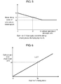
- Fig. 5 is a graph showing the relations of aforementioned parameters, such as stop time Te, open time tf of gas supply valve 10, and driving current If.
- Open time tf of gas supply valve 10 can be arbitrarily determined.
- open-time calculator 15 cannot perform calculation.
- open time tf should be several seconds.
- open-time calculator 15 calculates blower driving current Ie by expression (7). The calculation is performed under the condition where gas supply valve 10 is maintained to be closed while the gas pressure is decreasing to level B from level A that is the start-up pressure level of the lasing device after having stop time Te. The calculated value of blower driving current Ie is stored in the storage mounted on open-time calculator 15.
- Te and Ie correspond to Tx' and Ix', respectively, in expression (3).
- open-time calculator 15 calculates gradient ⁇ that represents correlation of blower driving current Ie with blower driving current If by expression (6).
- blower driving current Ie is obtained under the condition where gas supply valve 10 is maintained to be closed while the gas pressure is decreasing to level B from level A that is the start-up pressure level of the lasing device after having stop time Te.
- blower driving current If is obtained under the condition where gas supply valve 10 is maintained to be open for time tf while the gas pressure is decreasing to level B from level A.
- the calculated value of gradient ⁇ which corresponds to the gradient of the graph of Fig. 5 , is stored in the storage mounted on open-time calculator 15.
- step S10 to obtain optimum open time t of gas supply valve 10 from stop time T of the lasing device, proportional constant ⁇ is calculated by expression (11) derived from the expressions below.
- the calculated value of proportional constant ⁇ which corresponds to the gradient of the graph of Fig. 6 , is stored in the storage mounted on open-time calculator 15.
- step S11 the initial setting is completed (step S11).
- Gradient ⁇ represents degree of influence of the open time of gas supply valve 10 on the driving current for blower 4 with respect to stop time T of the lasing device.
- the open time of gas supply valve 10 capable of offering obtained blower driving current Id is the optimum value as open time t of gas supply valve 10.
- open time t of gas supply valve 10 is not a fixed value with respect to stop time T of the lasing device, varying as a function of the stop time of the lasing device. That is, value ⁇ calculated above serves as the coefficient thereof.
- the lasing device works on the normal operation procedures shown in the flowchart of Fig. 4 .
- step S12 the device reads stop time T counted by stop-time counter 16.
- open-time calculator 15 calculates open time t (at the start up of the device) of gas supply valve 10 by expression (10).
- step S14 gas supply valve 10 is open for time t during the gas pressure decreases from level A to level B.
- the lasing device is operated on the normal operation sequence (step S15).
- the aforementioned values ⁇ , ⁇ , and ⁇ should be calculated and stored in a table in advance when the followings have been measured in advance: the distance between gas canister 30 and gas supply valve 10, and the leakage quantity of the piping employed therebetween. This eliminates the processes shown in the flowchart of the initial setting shown in Fig. 3 , reducing the time required for installation of the lasing device.
- the mixture ratio of laser medium gas-retaining in the piping between the gas canister and the gas supply valve of the lasing device-can vary if the piping has a tiny pin hole and the gas leaks from the hole.
- the lasing device of the present invention provides laser output with stability in spite of a change in the mixture ratio of laser medium gas due to, for example, the problem above. Further, the structure of the present invention reduces costs by using decreased number of valves and suppresses consumption of laser medium gas. It is therefore useful for the lasing device employing laser medium gas.
Landscapes
- Physics & Mathematics (AREA)
- Electromagnetism (AREA)
- Engineering & Computer Science (AREA)
- Plasma & Fusion (AREA)
- Optics & Photonics (AREA)
- Lasers (AREA)
Applications Claiming Priority (2)
| Application Number | Priority Date | Filing Date | Title |
|---|---|---|---|
| JP2012114364 | 2012-05-18 | ||
| PCT/JP2013/001637 WO2013171951A1 (fr) | 2012-05-18 | 2013-03-13 | Dispositif à effet laser |
Publications (3)
| Publication Number | Publication Date |
|---|---|
| EP2852012A1 true EP2852012A1 (fr) | 2015-03-25 |
| EP2852012A4 EP2852012A4 (fr) | 2015-11-11 |
| EP2852012B1 EP2852012B1 (fr) | 2017-02-22 |
Family
ID=49583384
Family Applications (1)
| Application Number | Title | Priority Date | Filing Date |
|---|---|---|---|
| EP13791219.2A Active EP2852012B1 (fr) | 2012-05-18 | 2013-03-13 | Dispositif à effet laser |
Country Status (5)
| Country | Link |
|---|---|
| US (1) | US8897331B2 (fr) |
| EP (1) | EP2852012B1 (fr) |
| JP (1) | JP5810270B2 (fr) |
| CN (1) | CN103988378B (fr) |
| WO (1) | WO2013171951A1 (fr) |
Families Citing this family (5)
| Publication number | Priority date | Publication date | Assignee | Title |
|---|---|---|---|---|
| JP5877881B2 (ja) * | 2014-07-14 | 2016-03-08 | ファナック株式会社 | ガス圧及びガス消費量を制御可能なガスレーザ発振器 |
| JP2016096319A (ja) | 2014-11-17 | 2016-05-26 | ファナック株式会社 | レーザガスの供給配管の気密性を検査する機能を備えたガスレーザ装置 |
| JP6189883B2 (ja) * | 2015-01-29 | 2017-08-30 | ファナック株式会社 | レーザガスの組成比を判定するガスレーザ装置 |
| DE102022204308A1 (de) | 2022-05-02 | 2023-11-02 | Trumpf Lasersystems For Semiconductor Manufacturing Gmbh | Indirekt überwachte Laseranlage |
| WO2024047873A1 (fr) * | 2022-09-02 | 2024-03-07 | ファナック株式会社 | Dispositif de commande, système d'oscillateur laser à gaz et procédé de commande |
Family Cites Families (19)
| Publication number | Priority date | Publication date | Assignee | Title |
|---|---|---|---|---|
| JPS60214577A (ja) * | 1984-04-11 | 1985-10-26 | Matsushita Electric Ind Co Ltd | ガスレ−ザ発振装置 |
| JPS61154189A (ja) * | 1984-12-27 | 1986-07-12 | Matsushita Electric Ind Co Ltd | ガスレ−ザ装置 |
| JPH0783147B2 (ja) * | 1986-03-17 | 1995-09-06 | 株式会社アマダ | 気体レ−ザ発振器におけるレ−ザガス注入方法 |
| JPH01128581A (ja) | 1987-11-13 | 1989-05-22 | Toshiba Corp | ガスレーザ装置 |
| JPH0821744B2 (ja) | 1990-07-23 | 1996-03-04 | 松下電器産業株式会社 | ガスレーザ発振装置 |
| JP3824092B2 (ja) * | 1993-12-24 | 2006-09-20 | 株式会社小松製作所 | エキシマレ−ザ装置のガス補給方法 |
| JP3694359B2 (ja) | 1996-03-27 | 2005-09-14 | 株式会社ダイヘン | ガスレ−ザ発振器 |
| JPH10173274A (ja) | 1996-12-12 | 1998-06-26 | Komatsu Ltd | エキシマレーザ装置 |
| JP2001244525A (ja) | 2000-03-02 | 2001-09-07 | Matsushita Electric Ind Co Ltd | ガスレーザ発振装置 |
| JP3987300B2 (ja) | 2001-04-24 | 2007-10-03 | ファナック株式会社 | ガスレーザ発振器 |
| JP3858654B2 (ja) * | 2001-09-28 | 2006-12-20 | 松下電器産業株式会社 | ガスレーザ発振装置 |
| JP4656058B2 (ja) | 2004-04-21 | 2011-03-23 | 三菱電機株式会社 | ガスレーザ発振器およびガスレーザ加工機 |
| JP4095095B2 (ja) * | 2006-05-30 | 2008-06-04 | 株式会社小松製作所 | エキシマレーザ装置のガス補給方法 |
| JP4146867B2 (ja) * | 2006-06-22 | 2008-09-10 | ファナック株式会社 | ガスレーザ発振器 |
| JP4137972B2 (ja) * | 2006-12-14 | 2008-08-20 | ファナック株式会社 | ガス組成異常判断方法及び放電励起ガスレーザ発振器 |
| EP2388870B1 (fr) * | 2009-03-12 | 2017-05-03 | Panasonic Intellectual Property Management Co., Ltd. | Oscillateur laser et machine d'usinage au laser |
| JP2010212553A (ja) * | 2009-03-12 | 2010-09-24 | Panasonic Corp | レーザ発振装置およびレーザ加工機 |
| JP4782887B1 (ja) * | 2010-04-02 | 2011-09-28 | ファナック株式会社 | ガスレーザ装置 |
| JP4855529B2 (ja) * | 2010-04-05 | 2012-01-18 | ファナック株式会社 | 微小なレーザ出力を安定に制御するレーザ装置 |
-
2013
- 2013-03-13 EP EP13791219.2A patent/EP2852012B1/fr active Active
- 2013-03-13 WO PCT/JP2013/001637 patent/WO2013171951A1/fr active Application Filing
- 2013-03-13 CN CN201380004221.XA patent/CN103988378B/zh active Active
- 2013-03-13 JP JP2014515467A patent/JP5810270B2/ja active Active
-
2014
- 2014-05-15 US US14/278,146 patent/US8897331B2/en active Active
Also Published As
| Publication number | Publication date |
|---|---|
| EP2852012B1 (fr) | 2017-02-22 |
| CN103988378A (zh) | 2014-08-13 |
| US20140247855A1 (en) | 2014-09-04 |
| CN103988378B (zh) | 2017-02-01 |
| US8897331B2 (en) | 2014-11-25 |
| JPWO2013171951A1 (ja) | 2016-01-07 |
| JP5810270B2 (ja) | 2015-11-11 |
| WO2013171951A1 (fr) | 2013-11-21 |
| EP2852012A4 (fr) | 2015-11-11 |
Similar Documents
| Publication | Publication Date | Title |
|---|---|---|
| EP2852012B1 (fr) | Dispositif à effet laser | |
| JP6328683B2 (ja) | 小型チラーが使用可能なレーザ装置 | |
| US10461488B2 (en) | Laser device provided with function of predicting occurrence of condensation | |
| US20170307247A1 (en) | Heat source system, and control device and control method therefor | |
| US11747065B2 (en) | Refrigerant leak detection system and method | |
| KR101077422B1 (ko) | 유량 제어 시스템 | |
| EP1816712B1 (fr) | Oscillateur laser à gaz | |
| CN104078829B (zh) | 具有判定放电开始的功能的气体激光振荡器 | |
| US9502853B2 (en) | Gas laser device having function for discriminating type of alarm | |
| JP5829311B1 (ja) | ガス容器の密閉性を推定可能なガスレーザ発振器 | |
| JP2017045753A (ja) | 保守作業用の温度管理機能を有するレーザ装置 | |
| US9147994B2 (en) | Gas laser system capable of maintaining laser gas state during power supply cutoff | |
| JP2010127374A (ja) | 水素貯蔵システム | |
| US9590380B2 (en) | Laser oscillator provided with blower | |
| EP2778555A1 (fr) | Système de chauffage d'eau chaude, dispositif de commande et procédé de commande | |
| US20150222076A1 (en) | Gas laser system re-activatable without any damage within short time during recovery of power supply | |
| JP6709138B2 (ja) | ガス充填装置 | |
| EP3786515A1 (fr) | Dispositif de chargement de gaz | |
| KR20220084711A (ko) | 냉장고 및 그 제어방법 | |
| JP2009115361A (ja) | 冷却装置 |
Legal Events
| Date | Code | Title | Description |
|---|---|---|---|
| PUAI | Public reference made under article 153(3) epc to a published international application that has entered the european phase |
Free format text: ORIGINAL CODE: 0009012 |
|
| 17P | Request for examination filed |
Effective date: 20140313 |
|
| AK | Designated contracting states |
Kind code of ref document: A1 Designated state(s): AL AT BE BG CH CY CZ DE DK EE ES FI FR GB GR HR HU IE IS IT LI LT LU LV MC MK MT NL NO PL PT RO RS SE SI SK SM TR |
|
| AX | Request for extension of the european patent |
Extension state: BA ME |
|
| DAX | Request for extension of the european patent (deleted) | ||
| RA4 | Supplementary search report drawn up and despatched (corrected) |
Effective date: 20151009 |
|
| RIC1 | Information provided on ipc code assigned before grant |
Ipc: H01S 3/223 20060101ALI20151005BHEP Ipc: H01S 3/10 20060101ALI20151005BHEP Ipc: H01S 3/036 20060101ALI20151005BHEP Ipc: H01S 3/134 20060101AFI20151005BHEP Ipc: H01S 3/104 20060101ALI20151005BHEP |
|
| GRAP | Despatch of communication of intention to grant a patent |
Free format text: ORIGINAL CODE: EPIDOSNIGR1 |
|
| INTG | Intention to grant announced |
Effective date: 20160920 |
|
| GRAS | Grant fee paid |
Free format text: ORIGINAL CODE: EPIDOSNIGR3 |
|
| GRAJ | Information related to disapproval of communication of intention to grant by the applicant or resumption of examination proceedings by the epo deleted |
Free format text: ORIGINAL CODE: EPIDOSDIGR1 |
|
| GRAL | Information related to payment of fee for publishing/printing deleted |
Free format text: ORIGINAL CODE: EPIDOSDIGR3 |
|
| INTC | Intention to grant announced (deleted) | ||
| GRAR | Information related to intention to grant a patent recorded |
Free format text: ORIGINAL CODE: EPIDOSNIGR71 |
|
| GRAA | (expected) grant |
Free format text: ORIGINAL CODE: 0009210 |
|
| INTG | Intention to grant announced |
Effective date: 20170112 |
|
| AK | Designated contracting states |
Kind code of ref document: B1 Designated state(s): AL AT BE BG CH CY CZ DE DK EE ES FI FR GB GR HR HU IE IS IT LI LT LU LV MC MK MT NL NO PL PT RO RS SE SI SK SM TR |
|
| REG | Reference to a national code |
Ref country code: GB Ref legal event code: FG4D |
|
| REG | Reference to a national code |
Ref country code: CH Ref legal event code: EP |
|
| REG | Reference to a national code |
Ref country code: AT Ref legal event code: REF Ref document number: 869944 Country of ref document: AT Kind code of ref document: T Effective date: 20170315 |
|
| REG | Reference to a national code |
Ref country code: IE Ref legal event code: FG4D |
|
| REG | Reference to a national code |
Ref country code: DE Ref legal event code: R096 Ref document number: 602013017732 Country of ref document: DE |
|
| REG | Reference to a national code |
Ref country code: LT Ref legal event code: MG4D |
|
| REG | Reference to a national code |
Ref country code: NL Ref legal event code: MP Effective date: 20170222 |
|
| REG | Reference to a national code |
Ref country code: AT Ref legal event code: MK05 Ref document number: 869944 Country of ref document: AT Kind code of ref document: T Effective date: 20170222 |
|
| PG25 | Lapsed in a contracting state [announced via postgrant information from national office to epo] |
Ref country code: GR Free format text: LAPSE BECAUSE OF FAILURE TO SUBMIT A TRANSLATION OF THE DESCRIPTION OR TO PAY THE FEE WITHIN THE PRESCRIBED TIME-LIMIT Effective date: 20170523 Ref country code: NO Free format text: LAPSE BECAUSE OF FAILURE TO SUBMIT A TRANSLATION OF THE DESCRIPTION OR TO PAY THE FEE WITHIN THE PRESCRIBED TIME-LIMIT Effective date: 20170522 Ref country code: FI Free format text: LAPSE BECAUSE OF FAILURE TO SUBMIT A TRANSLATION OF THE DESCRIPTION OR TO PAY THE FEE WITHIN THE PRESCRIBED TIME-LIMIT Effective date: 20170222 Ref country code: LT Free format text: LAPSE BECAUSE OF FAILURE TO SUBMIT A TRANSLATION OF THE DESCRIPTION OR TO PAY THE FEE WITHIN THE PRESCRIBED TIME-LIMIT Effective date: 20170222 Ref country code: HR Free format text: LAPSE BECAUSE OF FAILURE TO SUBMIT A TRANSLATION OF THE DESCRIPTION OR TO PAY THE FEE WITHIN THE PRESCRIBED TIME-LIMIT Effective date: 20170222 |
|
| PG25 | Lapsed in a contracting state [announced via postgrant information from national office to epo] |
Ref country code: RS Free format text: LAPSE BECAUSE OF FAILURE TO SUBMIT A TRANSLATION OF THE DESCRIPTION OR TO PAY THE FEE WITHIN THE PRESCRIBED TIME-LIMIT Effective date: 20170222 Ref country code: BG Free format text: LAPSE BECAUSE OF FAILURE TO SUBMIT A TRANSLATION OF THE DESCRIPTION OR TO PAY THE FEE WITHIN THE PRESCRIBED TIME-LIMIT Effective date: 20170522 Ref country code: AT Free format text: LAPSE BECAUSE OF FAILURE TO SUBMIT A TRANSLATION OF THE DESCRIPTION OR TO PAY THE FEE WITHIN THE PRESCRIBED TIME-LIMIT Effective date: 20170222 Ref country code: SE Free format text: LAPSE BECAUSE OF FAILURE TO SUBMIT A TRANSLATION OF THE DESCRIPTION OR TO PAY THE FEE WITHIN THE PRESCRIBED TIME-LIMIT Effective date: 20170222 Ref country code: ES Free format text: LAPSE BECAUSE OF FAILURE TO SUBMIT A TRANSLATION OF THE DESCRIPTION OR TO PAY THE FEE WITHIN THE PRESCRIBED TIME-LIMIT Effective date: 20170222 Ref country code: NL Free format text: LAPSE BECAUSE OF FAILURE TO SUBMIT A TRANSLATION OF THE DESCRIPTION OR TO PAY THE FEE WITHIN THE PRESCRIBED TIME-LIMIT Effective date: 20170222 Ref country code: PT Free format text: LAPSE BECAUSE OF FAILURE TO SUBMIT A TRANSLATION OF THE DESCRIPTION OR TO PAY THE FEE WITHIN THE PRESCRIBED TIME-LIMIT Effective date: 20170622 Ref country code: LV Free format text: LAPSE BECAUSE OF FAILURE TO SUBMIT A TRANSLATION OF THE DESCRIPTION OR TO PAY THE FEE WITHIN THE PRESCRIBED TIME-LIMIT Effective date: 20170222 |
|
| PG25 | Lapsed in a contracting state [announced via postgrant information from national office to epo] |
Ref country code: IT Free format text: LAPSE BECAUSE OF FAILURE TO SUBMIT A TRANSLATION OF THE DESCRIPTION OR TO PAY THE FEE WITHIN THE PRESCRIBED TIME-LIMIT Effective date: 20170222 Ref country code: EE Free format text: LAPSE BECAUSE OF FAILURE TO SUBMIT A TRANSLATION OF THE DESCRIPTION OR TO PAY THE FEE WITHIN THE PRESCRIBED TIME-LIMIT Effective date: 20170222 Ref country code: RO Free format text: LAPSE BECAUSE OF FAILURE TO SUBMIT A TRANSLATION OF THE DESCRIPTION OR TO PAY THE FEE WITHIN THE PRESCRIBED TIME-LIMIT Effective date: 20170222 Ref country code: SK Free format text: LAPSE BECAUSE OF FAILURE TO SUBMIT A TRANSLATION OF THE DESCRIPTION OR TO PAY THE FEE WITHIN THE PRESCRIBED TIME-LIMIT Effective date: 20170222 Ref country code: CZ Free format text: LAPSE BECAUSE OF FAILURE TO SUBMIT A TRANSLATION OF THE DESCRIPTION OR TO PAY THE FEE WITHIN THE PRESCRIBED TIME-LIMIT Effective date: 20170222 |
|
| REG | Reference to a national code |
Ref country code: CH Ref legal event code: PL |
|
| REG | Reference to a national code |
Ref country code: DE Ref legal event code: R097 Ref document number: 602013017732 Country of ref document: DE |
|
| PG25 | Lapsed in a contracting state [announced via postgrant information from national office to epo] |
Ref country code: MC Free format text: LAPSE BECAUSE OF FAILURE TO SUBMIT A TRANSLATION OF THE DESCRIPTION OR TO PAY THE FEE WITHIN THE PRESCRIBED TIME-LIMIT Effective date: 20170222 Ref country code: SM Free format text: LAPSE BECAUSE OF FAILURE TO SUBMIT A TRANSLATION OF THE DESCRIPTION OR TO PAY THE FEE WITHIN THE PRESCRIBED TIME-LIMIT Effective date: 20170222 Ref country code: DK Free format text: LAPSE BECAUSE OF FAILURE TO SUBMIT A TRANSLATION OF THE DESCRIPTION OR TO PAY THE FEE WITHIN THE PRESCRIBED TIME-LIMIT Effective date: 20170222 Ref country code: PL Free format text: LAPSE BECAUSE OF FAILURE TO SUBMIT A TRANSLATION OF THE DESCRIPTION OR TO PAY THE FEE WITHIN THE PRESCRIBED TIME-LIMIT Effective date: 20170222 |
|
| REG | Reference to a national code |
Ref country code: IE Ref legal event code: MM4A |
|
| PLBE | No opposition filed within time limit |
Free format text: ORIGINAL CODE: 0009261 |
|
| REG | Reference to a national code |
Ref country code: FR Ref legal event code: ST Effective date: 20171130 |
|
| STAA | Information on the status of an ep patent application or granted ep patent |
Free format text: STATUS: NO OPPOSITION FILED WITHIN TIME LIMIT |
|
| GBPC | Gb: european patent ceased through non-payment of renewal fee |
Effective date: 20170522 |
|
| 26N | No opposition filed |
Effective date: 20171123 |
|
| PG25 | Lapsed in a contracting state [announced via postgrant information from national office to epo] |
Ref country code: LU Free format text: LAPSE BECAUSE OF NON-PAYMENT OF DUE FEES Effective date: 20170313 Ref country code: FR Free format text: LAPSE BECAUSE OF NON-PAYMENT OF DUE FEES Effective date: 20170424 |
|
| PG25 | Lapsed in a contracting state [announced via postgrant information from national office to epo] |
Ref country code: IE Free format text: LAPSE BECAUSE OF NON-PAYMENT OF DUE FEES Effective date: 20170313 Ref country code: LI Free format text: LAPSE BECAUSE OF NON-PAYMENT OF DUE FEES Effective date: 20170331 Ref country code: CH Free format text: LAPSE BECAUSE OF NON-PAYMENT OF DUE FEES Effective date: 20170331 Ref country code: SI Free format text: LAPSE BECAUSE OF FAILURE TO SUBMIT A TRANSLATION OF THE DESCRIPTION OR TO PAY THE FEE WITHIN THE PRESCRIBED TIME-LIMIT Effective date: 20170222 |
|
| REG | Reference to a national code |
Ref country code: BE Ref legal event code: MM Effective date: 20170331 |
|
| PG25 | Lapsed in a contracting state [announced via postgrant information from national office to epo] |
Ref country code: GB Free format text: LAPSE BECAUSE OF NON-PAYMENT OF DUE FEES Effective date: 20170522 |
|
| PG25 | Lapsed in a contracting state [announced via postgrant information from national office to epo] |
Ref country code: BE Free format text: LAPSE BECAUSE OF NON-PAYMENT OF DUE FEES Effective date: 20170331 |
|
| PG25 | Lapsed in a contracting state [announced via postgrant information from national office to epo] |
Ref country code: MT Free format text: LAPSE BECAUSE OF NON-PAYMENT OF DUE FEES Effective date: 20170313 |
|
| PG25 | Lapsed in a contracting state [announced via postgrant information from national office to epo] |
Ref country code: HU Free format text: LAPSE BECAUSE OF FAILURE TO SUBMIT A TRANSLATION OF THE DESCRIPTION OR TO PAY THE FEE WITHIN THE PRESCRIBED TIME-LIMIT; INVALID AB INITIO Effective date: 20130313 |
|
| PG25 | Lapsed in a contracting state [announced via postgrant information from national office to epo] |
Ref country code: CY Free format text: LAPSE BECAUSE OF FAILURE TO SUBMIT A TRANSLATION OF THE DESCRIPTION OR TO PAY THE FEE WITHIN THE PRESCRIBED TIME-LIMIT Effective date: 20170222 |
|
| PG25 | Lapsed in a contracting state [announced via postgrant information from national office to epo] |
Ref country code: MK Free format text: LAPSE BECAUSE OF FAILURE TO SUBMIT A TRANSLATION OF THE DESCRIPTION OR TO PAY THE FEE WITHIN THE PRESCRIBED TIME-LIMIT Effective date: 20170222 |
|
| PG25 | Lapsed in a contracting state [announced via postgrant information from national office to epo] |
Ref country code: TR Free format text: LAPSE BECAUSE OF FAILURE TO SUBMIT A TRANSLATION OF THE DESCRIPTION OR TO PAY THE FEE WITHIN THE PRESCRIBED TIME-LIMIT Effective date: 20170222 |
|
| PG25 | Lapsed in a contracting state [announced via postgrant information from national office to epo] |
Ref country code: AL Free format text: LAPSE BECAUSE OF FAILURE TO SUBMIT A TRANSLATION OF THE DESCRIPTION OR TO PAY THE FEE WITHIN THE PRESCRIBED TIME-LIMIT Effective date: 20170222 Ref country code: IS Free format text: LAPSE BECAUSE OF FAILURE TO SUBMIT A TRANSLATION OF THE DESCRIPTION OR TO PAY THE FEE WITHIN THE PRESCRIBED TIME-LIMIT Effective date: 20170622 |
|
| PGFP | Annual fee paid to national office [announced via postgrant information from national office to epo] |
Ref country code: DE Payment date: 20220609 Year of fee payment: 11 |