EP2851542A2 - Gesteuertes Motorabschaltverfahren und Motorabschaltvorhersage für Abgassystembeständigkeit - Google Patents
Gesteuertes Motorabschaltverfahren und Motorabschaltvorhersage für Abgassystembeständigkeit Download PDFInfo
- Publication number
- EP2851542A2 EP2851542A2 EP20140156993 EP14156993A EP2851542A2 EP 2851542 A2 EP2851542 A2 EP 2851542A2 EP 20140156993 EP20140156993 EP 20140156993 EP 14156993 A EP14156993 A EP 14156993A EP 2851542 A2 EP2851542 A2 EP 2851542A2
- Authority
- EP
- European Patent Office
- Prior art keywords
- shutdown
- engine shutdown
- engine
- machine
- predicting
- Prior art date
- Legal status (The legal status is an assumption and is not a legal conclusion. Google has not performed a legal analysis and makes no representation as to the accuracy of the status listed.)
- Granted
Links
Images
Classifications
-
- F—MECHANICAL ENGINEERING; LIGHTING; HEATING; WEAPONS; BLASTING
- F02—COMBUSTION ENGINES; HOT-GAS OR COMBUSTION-PRODUCT ENGINE PLANTS
- F02N—STARTING OF COMBUSTION ENGINES; STARTING AIDS FOR SUCH ENGINES, NOT OTHERWISE PROVIDED FOR
- F02N11/00—Starting of engines by means of electric motors
- F02N11/08—Circuits specially adapted for starting of engines
- F02N11/0814—Circuits specially adapted for starting of engines comprising means for controlling automatic idle-start-stop
- F02N11/0818—Conditions for starting or stopping the engine or for deactivating the idle-start-stop mode
- F02N11/0829—Conditions for starting or stopping the engine or for deactivating the idle-start-stop mode related to special engine control, e.g. giving priority to engine warming-up or learning
-
- F—MECHANICAL ENGINEERING; LIGHTING; HEATING; WEAPONS; BLASTING
- F02—COMBUSTION ENGINES; HOT-GAS OR COMBUSTION-PRODUCT ENGINE PLANTS
- F02D—CONTROLLING COMBUSTION ENGINES
- F02D41/00—Electrical control of supply of combustible mixture or its constituents
- F02D41/02—Circuit arrangements for generating control signals
- F02D41/021—Introducing corrections for particular conditions exterior to the engine
- F02D41/0235—Introducing corrections for particular conditions exterior to the engine in relation with the state of the exhaust gas treating apparatus
- F02D41/027—Introducing corrections for particular conditions exterior to the engine in relation with the state of the exhaust gas treating apparatus to purge or regenerate the exhaust gas treating apparatus
- F02D41/029—Introducing corrections for particular conditions exterior to the engine in relation with the state of the exhaust gas treating apparatus to purge or regenerate the exhaust gas treating apparatus the exhaust gas treating apparatus being a particulate filter
-
- F—MECHANICAL ENGINEERING; LIGHTING; HEATING; WEAPONS; BLASTING
- F02—COMBUSTION ENGINES; HOT-GAS OR COMBUSTION-PRODUCT ENGINE PLANTS
- F02D—CONTROLLING COMBUSTION ENGINES
- F02D41/00—Electrical control of supply of combustible mixture or its constituents
- F02D41/02—Circuit arrangements for generating control signals
- F02D41/04—Introducing corrections for particular operating conditions
- F02D41/042—Introducing corrections for particular operating conditions for stopping the engine
-
- F—MECHANICAL ENGINEERING; LIGHTING; HEATING; WEAPONS; BLASTING
- F02—COMBUSTION ENGINES; HOT-GAS OR COMBUSTION-PRODUCT ENGINE PLANTS
- F02D—CONTROLLING COMBUSTION ENGINES
- F02D41/00—Electrical control of supply of combustible mixture or its constituents
- F02D41/02—Circuit arrangements for generating control signals
- F02D41/14—Introducing closed-loop corrections
- F02D41/1438—Introducing closed-loop corrections using means for determining characteristics of the combustion gases; Sensors therefor
- F02D41/1444—Introducing closed-loop corrections using means for determining characteristics of the combustion gases; Sensors therefor characterised by the characteristics of the combustion gases
- F02D41/1446—Introducing closed-loop corrections using means for determining characteristics of the combustion gases; Sensors therefor characterised by the characteristics of the combustion gases the characteristics being exhaust temperatures
-
- F—MECHANICAL ENGINEERING; LIGHTING; HEATING; WEAPONS; BLASTING
- F02—COMBUSTION ENGINES; HOT-GAS OR COMBUSTION-PRODUCT ENGINE PLANTS
- F02N—STARTING OF COMBUSTION ENGINES; STARTING AIDS FOR SUCH ENGINES, NOT OTHERWISE PROVIDED FOR
- F02N11/00—Starting of engines by means of electric motors
- F02N11/08—Circuits specially adapted for starting of engines
- F02N11/0814—Circuits specially adapted for starting of engines comprising means for controlling automatic idle-start-stop
- F02N11/0818—Conditions for starting or stopping the engine or for deactivating the idle-start-stop mode
-
- F—MECHANICAL ENGINEERING; LIGHTING; HEATING; WEAPONS; BLASTING
- F02—COMBUSTION ENGINES; HOT-GAS OR COMBUSTION-PRODUCT ENGINE PLANTS
- F02D—CONTROLLING COMBUSTION ENGINES
- F02D41/00—Electrical control of supply of combustible mixture or its constituents
- F02D41/02—Circuit arrangements for generating control signals
- F02D41/14—Introducing closed-loop corrections
- F02D41/1401—Introducing closed-loop corrections characterised by the control or regulation method
- F02D2041/1412—Introducing closed-loop corrections characterised by the control or regulation method using a predictive controller
-
- F—MECHANICAL ENGINEERING; LIGHTING; HEATING; WEAPONS; BLASTING
- F02—COMBUSTION ENGINES; HOT-GAS OR COMBUSTION-PRODUCT ENGINE PLANTS
- F02D—CONTROLLING COMBUSTION ENGINES
- F02D41/00—Electrical control of supply of combustible mixture or its constituents
- F02D41/22—Safety or indicating devices for abnormal conditions
- F02D2041/228—Warning displays
-
- F—MECHANICAL ENGINEERING; LIGHTING; HEATING; WEAPONS; BLASTING
- F02—COMBUSTION ENGINES; HOT-GAS OR COMBUSTION-PRODUCT ENGINE PLANTS
- F02D—CONTROLLING COMBUSTION ENGINES
- F02D2200/00—Input parameters for engine control
- F02D2200/02—Input parameters for engine control the parameters being related to the engine
- F02D2200/08—Exhaust gas treatment apparatus parameters
- F02D2200/0802—Temperature of the exhaust gas treatment apparatus
-
- F—MECHANICAL ENGINEERING; LIGHTING; HEATING; WEAPONS; BLASTING
- F02—COMBUSTION ENGINES; HOT-GAS OR COMBUSTION-PRODUCT ENGINE PLANTS
- F02D—CONTROLLING COMBUSTION ENGINES
- F02D2200/00—Input parameters for engine control
- F02D2200/70—Input parameters for engine control said parameters being related to the vehicle exterior
- F02D2200/701—Information about vehicle position, e.g. from navigation system or GPS signal
-
- F—MECHANICAL ENGINEERING; LIGHTING; HEATING; WEAPONS; BLASTING
- F02—COMBUSTION ENGINES; HOT-GAS OR COMBUSTION-PRODUCT ENGINE PLANTS
- F02D—CONTROLLING COMBUSTION ENGINES
- F02D41/00—Electrical control of supply of combustible mixture or its constituents
- F02D41/02—Circuit arrangements for generating control signals
- F02D41/021—Introducing corrections for particular conditions exterior to the engine
- F02D41/0215—Introducing corrections for particular conditions exterior to the engine in relation with elements of the transmission
- F02D41/0225—Introducing corrections for particular conditions exterior to the engine in relation with elements of the transmission in relation with the gear ratio or shift lever position
-
- F—MECHANICAL ENGINEERING; LIGHTING; HEATING; WEAPONS; BLASTING
- F02—COMBUSTION ENGINES; HOT-GAS OR COMBUSTION-PRODUCT ENGINE PLANTS
- F02N—STARTING OF COMBUSTION ENGINES; STARTING AIDS FOR SUCH ENGINES, NOT OTHERWISE PROVIDED FOR
- F02N2200/00—Parameters used for control of starting apparatus
- F02N2200/08—Parameters used for control of starting apparatus said parameters being related to the vehicle or its components
- F02N2200/0802—Transmission state, e.g. gear ratio or neutral state
-
- Y—GENERAL TAGGING OF NEW TECHNOLOGICAL DEVELOPMENTS; GENERAL TAGGING OF CROSS-SECTIONAL TECHNOLOGIES SPANNING OVER SEVERAL SECTIONS OF THE IPC; TECHNICAL SUBJECTS COVERED BY FORMER USPC CROSS-REFERENCE ART COLLECTIONS [XRACs] AND DIGESTS
- Y02—TECHNOLOGIES OR APPLICATIONS FOR MITIGATION OR ADAPTATION AGAINST CLIMATE CHANGE
- Y02T—CLIMATE CHANGE MITIGATION TECHNOLOGIES RELATED TO TRANSPORTATION
- Y02T10/00—Road transport of goods or passengers
- Y02T10/10—Internal combustion engine [ICE] based vehicles
- Y02T10/40—Engine management systems
Definitions
- the present invention generally relates to the field of software control of motorized machinery and more specifically to software prediction and control of engine shutdown for exhaust system durability.
- Modem machinery can include one or more subsystems in their exhaust systems, for example subsystems to reduce emissions of certain materials for compliance with emissions regulations. Some of these subsystems may be more susceptible to damage from heat or other factors than other exhaust subsystems. It would be desirable to have systems in place that can help protect some of these more susceptible subsystems from factors that can reduce their effectiveness or durability.
- a machine exhaust system can include a diesel particulate filter (DPF), a DPF regeneration system, and a diesel exhaust fluid (DEF) dosing unit.
- DPF diesel particulate filter
- DEF diesel exhaust fluid
- the DPF collects soot and other particulates in the machine exhaust.
- diesel fuel can be used to increase exhaust temperatures and clean the DPF.
- the DEF dosing unit can be used to inject urea into the exhaust stream in order to reduce NOx to meet emissions regulations.
- the DEF dosing unit can be installed downstream of the DPF where, during DPF regenerations, exhaust temperatures can become significantly elevated. In this scenario, during DPF regenerations, the DEF dosing unit is also exposed to these high exhaust temperatures used for cleaning the DPF.
- the DEF dosing unit can be cooled by both engine coolant and the urea that it is injecting while the engine is running. If the machine is shutdown during DPF regeneration, the elevated exhaust temperatures and exhaust energy can be trapped in the insulated exhaust tubing. The DEF dosing unit is then trapped in significantly high temperatures for a long period of time, which can lead to component damage and ultimately component failure.
- the DEF dosing unit is most susceptible to failure during this shutdown condition (engine not running), because when the engine is shutdown, the engine coolant and urea flow which usually cool the DEF dosing unit also stop. Thus, for this situation, it would be desirable to have systems in place that would delay engine shutdown to allow sufficient cooling of the DEF dosing unit.
- a controlled engine shutdown method for a machine having an engine and an exhaust system.
- the controlled engine shutdown method includes monitoring an exhaust system temperature, monitoring operator commands including an engine shutdown command, and delaying engine shutdown when the operator issues an engine shutdown command based on whether the exhaust system temperature exceeds a temperature threshold.
- the controlled engine shutdown method can also include, if engine shutdown is delayed, aborting any current process of the machine that is affecting exhaust temperatures.
- the exhaust system can include a diesel particulate filter (DPF), and a DPF regeneration process that affects exhaust system temperature can be used to clean the DPF. Aborting any current process of the machine that is affecting exhaust temperatures can include aborting any current DPF regeneration process.
- the controlled engine shutdown can also include enabling the operator to override the shutdown delay and proceed immediately to engine shutdown.
- the controlled engine shutdown method can include setting a shutdown timer to a timer start value when the exhaust system temperature crosses and exceeds the temperature threshold. In an embodiment with the shutdown timer, if the shutdown timer is zero when the operator issues an engine shutdown command, the method does not delay the engine shutdown; and if the shutdown timer is greater than zero when the operator issues an engine shutdown command, the method delays shutdown of the engine until the shutdown timer counts down to zero.
- the controlled engine shutdown method can also include predicting when an engine shutdown is expected and inhibiting any process of the machine that would affect exhaust temperatures when an engine shutdown is predicted. The method can also include not counting down the shutdown timer when the exhaust system temperature exceeds the temperature threshold and an engine shutdown is not predicted; but counting down the shutdown timer when the exhaust system temperature exceeds the temperature threshold and an engine shutdown is predicted.
- the controlled engine shutdown method can also include, when engine shutdown is being delayed, displaying a notification message visible to the operator indicating that engine shutdown is being delayed.
- the notification message can include a timer indicating how much longer engine shutdown is being delayed.
- the notification message can also include an override selection enabling the operator to override the shutdown delay and proceed immediately to engine shutdown.
- the controlled engine shutdown method can also include predicting when an engine shutdown is expected, and delaying or aborting any process of the machine that would affect exhaust temperatures when an engine shutdown is predicted. Predicting when an engine shutdown is expected can include monitoring various states of the machine, determining one or more monitored states that indicate an operator is preparing to shut down the machine, and predicting an engine shutdown when the one or more monitored states indicate the operator is preparing to shut down the machine. Predicting when an engine shutdown is expected can include monitoring the gear selection for the machine, and predicting an engine shutdown when the machine is put into a parking gear.
- Predicting when an engine shutdown is expected can include monitoring a fluid level of the machine, and predicting an engine shutdown when the fluid level goes below a fluid threshold. Predicting when an engine shutdown is expected can include determining a geographic shutdown area where the machine is usually shutdown, monitoring a current geographic position of the machine, determining a shutdown time of day when the machine is usually shutdown, monitoring a current time of day, and predicting an engine shutdown when the current geographic position of the machine is within the geographic shutdown area, and the current time of day is within a threshold time of the shutdown time of day.
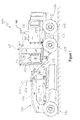
- FIG 1 illustrates an exemplary embodiment of a machine, such as a motor grader 600 for spreading and leveling dirt, gravel, or other materials.
- a motor grader is the 772G Motor Grader manufactured and sold by John Deere & Company.
- the motor grader 600 includes an articulated chassis formed by front and rear frames 602 and 604, respectively.
- the front frame 602 is supported by a pair of front wheels 606, and the rear frame 604 is supported on right and left tandem sets of rear wheels 608.
- the front and rear wheels may take the form of any type of traction device depending on the machine.
- An operator cab 610 is mounted on an upwardly and forwardly inclined rear region 612 of the front frame 602.
- An engine 618 is mounted on the rear frame 604 and supplies power for all driven components of the motor grader 600.
- An exhaust system which includes exhaust pipe 640 is coupled to the engine 618 and can filter or otherwise process and direct the emissions from the engine 618.
- the engine 618 can drive a transmission 636 or other power-transferring drivetrain, which is coupled for driving the rear wheels 608 at various selected speeds and either in forward or reverse modes.
- a hydrostatic front wheel assist transmission (not shown) may be selectively engaged to power the front wheels 606, in a manner known in the art.
- a drawbar or draft frame 620 Mounted to a front location of the front frame 602 is a drawbar or draft frame 620, having a forward end universally connected to the front frame 602 by a ball and socket arrangement 622 and having opposite right and left rear regions suspended from an elevated central section 624 of the front frame 602 by right and left lift linkage arrangements including right and left extensible and retractable hydraulic actuators 626 and 628, respectively.
- a side shift linkage arrangement is coupled between the elevated frame section 624 and a rear location of the drawbar 620 and includes an extensible and retractable side swing hydraulic actuator 630.
- a blade 632 is coupled to the front frame 602 and powered by a circle drive assembly 634.
- the features described above and shown in Figure 1 may be provided on other machines or vehicles having one or more ground engaging work tools or traction devices, such as wheels and tracks, used for construction, agricultural, forestry and other purposes.
- the blade 632 of the motor grader 600 may also take the form of other known ground-engaging tools such as a snow plow and may engage other materials besides dirt, gravel, sand, etc.
- the operator cab 610 of Figure 1 can include a front wall, a pair of side walls, a rear wall, a roof, and a floor that define an interior space of the operator cab 610. Windows can be formed in any one of the walls.
- the operator cab 610 can include at least one operator's seat positioned therein and various controls for operating the motor grader 600 disposed so as to be within the reach of an operator.
- these controls may include a steering wheel 614 and a shift assembly 616.
- the steering wheel 614 can control the steering of the motor grader 600.
- the shift assembly 616 may be used for controlling the transmission 636.
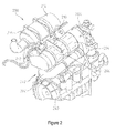
- FIG. 2 illustrates an exemplary exhaust system 200 coupled to an exemplary engine 240.
- Exhaust gases exit the engine 240 and wrap through the exhaust system 200.
- the exhaust gases exit the engine 240 at an engine outlet 242 and enter an exhaust pipe 202 of the exhaust system 200 which leads to a diesel oxidation catalyst (DOC)/diesel particulate filter (DPF) can 204.
- the DOC/DPF can 204 includes the DOC at the front end and the DPF 206 at the back end.
- the DPF 206 collects soot and during DPF regeneration, diesel fuel is injected into the DOC/DPF can 204 through a diesel fuel injector 208 and ignited to bum off the soot from the DPF 206.
- DOC diesel oxidation catalyst
- DPF diesel particulate filter
- the DOC/DPF can 204 can also include temperature and pressure sensors.
- the DPF regeneration cleans the DPF 206 and prevents clogging of the exhaust system 200.
- An exhaust system can periodically perform DPF regeneration and can reach high temperatures during DPF regeneration.
- the exhaust stream passes through the DPF 206 and enters a decomposition tube 210.
- a urea injector 212 injects urea into the exhaust stream in the decomposition tube 210 and the urea is decomposed into ammonia.
- the exhaust stream After passing through the decomposition tube 210, the exhaust stream enters a selective catalytic reduction (SCR) can 214 where the NOx reacts with the ammonia to produce nitrogen and water.
- the SCR can 214 can also include NOx sensors and temperature sensors. The remaining ammonia that gets through the SCR 214 can be further cleaned up by an ammonia oxidation catalyst (AOC) 216.
- AOC ammonia oxidation catalyst
- Processes can be initiated in the exhaust system 200, for example the igniting of diesel fuel during DPF regeneration, that generate high exhaust temperatures that can be deleterious to components of the exhaust system 200.
- DPF regeneration will be used throughout this disclosure as a general term encompassing not only a diesel particulate filter regeneration process but any time the engine control system is intentionally elevating exhaust temperatures. This could be for: DPF regeneration, DOC hydro-carbon cleanout, urea crystallization sublimation, selective catalytic reduction (SCR) de-sulfurization, and any other instances where elevated exhaust temperatures are produced.
- sensors or injectors in the exhaust system 200 can include plastic or electronic parts that can be damaged by high exhaust temperatures. While the engine 240 is running, engine coolant, injected urea and other processes help dissipate the high exhaust temperatures. However, these heat dissipating processes are usually shut down when the engine 240 is shut down.
- a control system can delay the shutdown of a machine engine upon the operator requesting a shutdown when a high exhaust temperature process, for example DPF regeneration, is underway.
- the control system can delay the engine shutdown and/or abort the DPF regeneration, and idle the engine for a period of time in order to cool the exhaust system. The operator could still have the option to override the delay and immediately proceed with the shutdown if needed.
- the damage that can be caused to more heat susceptible systems usually occurs when the engine is shut down during a DPF regeneration because cooling processes that help in cooling these heat susceptible systems will usually stop when the engine is shutdown.
- the control system can delay the engine shutdown to allow the cooling processes to continue when the operator initiates the shutdown procedure. During the time period where the engine shutdown is delayed, the control system can also abort the DPF regeneration to decrease the exhaust temperatures more rapidly. When the engine finally shuts down, the exhaust temperatures will have been sufficiently lowered so that the risk of damage to the heat susceptible systems will be mitigated.
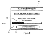
- the control system can display a warning message on an operator display of the machine that the exhaust system requires a cooldown period.
- the control system can also abort the DPF regeneration.
- a timer or progress bar can be displayed on the operator display that indicates the amount of time remaining in the cooldown period. The operator can elect to override the delay and continue with the shutdown. If the operator elects not to override the shutdown delay, the engine will automatically shut itself off when the timer or progress bar expires.
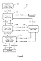
- FIG. 3 illustrates an exemplary embodiment of a flow diagram 300 for the control system that includes prediction of operator shutdown.
- the ignition switch is wired to a vehicle control unit (VCU) which receives a signal when the operator activates the ignition switch to start or shutdown the machine.
- VCU vehicle control unit
- a shutdown timer is set to 0
- an inhibit flag is set to FALSE
- a shutdown prediction flag (SD Pred) is set to FALSE.
- the inhibit flag indicates whether DPF regeneration is being turned off (inhibited) to lower exhaust temperatures.
- the shutdown timer indicates the time duration of the shutdown delay in which the machine engine idles.
- the shutdown prediction flag indicates whether the control system currently predicts that the operator will soon issue a machine shutdown command.
- a start flag is set to TRUE and control passes to block 304.
- the start flag indicates whether the current operator command is for engine running (TRUE) or shutdown (FALSE).
- the engine is running and the exhaust temperature is not above a temperature threshold.
- Exhaust temperatures can be monitored using various methods known in the art, for example monitored using physical temperature sensors, modeled or predicted using other parameters and/or virtual sensors, etc.
- a high temperature (HT) flag can be set to indicate whether the exhaust system is above a temperature threshold.
- the shutdown timer is set to 0 and the inhibit flag is set to FALSE.
- the start flag is set to FALSE indicating that the current operator command is for engine shutdown and the engine is shut down without delay.
- the shutdown timer is set to a maximum timer value, and the inhibit flag is set to FALSE.
- the control system predicts that the operator will soon issue a shutdown command
- the start flag is set to FALSE and control passes to block 310.
- the shutdown timer starts or continues counting down to 0, and the inhibit flag is set to TRUE.
- the control system predicts that the operator will not soon issue a shutdown command
- the start flag is set to FALSE and control passes to block 310.
- the inhibit flag is set to TRUE indicating that DPF regeneration is currently being inhibited
- a notification window is displayed for the operator and the shutdown timer starts or continues counting down.
- An exemplary cooldown notification window 400 is illustrated in Figure 4 .
- the notification window 400 includes an active timer 402, a progress bar 404 and a cooldown override selection 406 which the operator can select to override the delay and immediately begin engine shutdown.
- the machine engine is shutdown.
- the start flag is set to TRUE indicating that the current operator command is for engine running and control passes to block 308.
- the operator selects the cooldown override selection 406 or otherwise elects to override the delay and immediately begin engine shutdown, the machine engine is shutdown.
- the control system can use various methods to predict when an operator is most likely to shut down the engine on a machine. If it is predicted that the operator will shut down the engine, then the control system can avoid or abort a DPF regeneration in order to start cooling the exhaust system prior to the predicted engine shutdown. Some exemplary shutdown prediction methods that the control system can use are described below.
- a first exemplary shutdown prediction method is a learning method in which different states of the machine are monitored and the control system looks for a combination of monitored states that indicate the operator is preparing the machine for shutdown. For example, on a Motor Grader, a probable time when an operator will shut down the engine is when the transmission is placed from a working gear to the park position ("PARK"). There are few instances when a Motor Grader operator would transition to "PARK" and not shutdown the engine. For another example, on an articulated dump truck (ADT), a probable time when an operator will shut down the engine is when the transmission is placed in "PARK" and the dump bed is fully raised in the stowed position. In yet other examples, the bucket position can be monitored for a loader, or the seat position can be monitored for a backhoe. One or more monitored states can be used to predict a machine shutdown.
- a second exemplary shutdown prediction method is to use machine statistics (for example, JDLink data in the case of John Deere equipment) to determine the average activity interval (time between consecutive shutdown periods) for a given machine model.
- machine statistics for example, JDLink data in the case of John Deere equipment
- the average Motor Grader activity interval may be approximately two hours.
- the control system could abort a DPF regeneration that is occurring at about two hours of machine operation since it is likely that an engine shutdown will occur soon.
- a third exemplary shutdown prediction method is similar to the second method, except a specific machine's control system keeps a running average activity interval for that specific machine (instead of a population average activity interval for that type of machine) to use in the computation. In this case, the activity interval would change over time as the machine usage changes.
- a fourth exemplary shutdown prediction method uses onboard GPS of the machine.
- the control system can learn an area where a machine is typically shutdown, for example a machinery parking area. Once the machine enters this typical shutdown area, the control system could abort DPF regeneration.
- a fifth exemplary shutdown prediction method uses time of day.
- the software control system can learn the time of day when the machine is typically shutdown. At a specified number of minutes before this time of day, the software control system can abort DPF regeneration.
- a sixth exemplary shutdown prediction method could observe fuel level and/or other machine tank levels, for example a DEF tank level. When one or more of these levels are very low, it is likely that the operator would shut down the machine to refill the fuel and/or other tank(s). When one or more of these tank levels are below some applicable threshold, the control system can abort DPF regeneration.
- exemplary shutdown prediction methods can also be combined with one another or other methods.
- the fourth and fifth exemplary shutdown prediction methods could be combined such that the control system learns the geographic area where and time of day when a machine is typically shutdown. When the machine enters its typical shutdown area within a few minutes before or after its typical shutdown time, the control system could abort DPF regeneration.
Landscapes
- Engineering & Computer Science (AREA)
- Chemical & Material Sciences (AREA)
- Combustion & Propulsion (AREA)
- Mechanical Engineering (AREA)
- General Engineering & Computer Science (AREA)
- Processes For Solid Components From Exhaust (AREA)
- Combined Controls Of Internal Combustion Engines (AREA)
Applications Claiming Priority (1)
| Application Number | Priority Date | Filing Date | Title |
|---|---|---|---|
| US14/029,881 US9404464B2 (en) | 2013-09-18 | 2013-09-18 | Controlled engine shutdown method and engine shutdown prediction for exhaust system durability |
Publications (3)
| Publication Number | Publication Date |
|---|---|
| EP2851542A2 true EP2851542A2 (de) | 2015-03-25 |
| EP2851542A3 EP2851542A3 (de) | 2015-06-24 |
| EP2851542B1 EP2851542B1 (de) | 2017-09-20 |
Family
ID=50193272
Family Applications (1)
| Application Number | Title | Priority Date | Filing Date |
|---|---|---|---|
| EP14156993.9A Active EP2851542B1 (de) | 2013-09-18 | 2014-02-27 | Gesteuertes Motorabschaltverfahren und Motorabschaltvorhersage für Abgassystembeständigkeit |
Country Status (2)
| Country | Link |
|---|---|
| US (1) | US9404464B2 (de) |
| EP (1) | EP2851542B1 (de) |
Cited By (1)
| Publication number | Priority date | Publication date | Assignee | Title |
|---|---|---|---|---|
| EP3663550A4 (de) * | 2017-07-31 | 2020-11-25 | Yanmar Power Technology Co., Ltd. | Nutzfahrzeug |
Families Citing this family (12)
| Publication number | Priority date | Publication date | Assignee | Title |
|---|---|---|---|---|
| WO2017003425A1 (en) | 2015-06-29 | 2017-01-05 | Cummins, Inc. | Managing automatic stop/start frequency |
| WO2017048246A1 (en) * | 2015-09-16 | 2017-03-23 | Cummins Inc. | Integrated start/stop and after-treatment controls |
| US10701859B2 (en) | 2016-01-07 | 2020-07-07 | Exmark Manufacturing Company, Incorporated | Electronic controller and turf maintenance vehicle incorporating same |
| US10815915B2 (en) | 2018-09-06 | 2020-10-27 | Exmark Manufacturing Company, Inc. | Systems and methods for determining an engine cool-down period and grounds maintenance vehicles incorporating same |
| KR102734271B1 (ko) * | 2019-11-04 | 2024-11-25 | 에이치디현대인프라코어 주식회사 | 건설기계의 운행 제어 방법 |
| US11879405B2 (en) * | 2021-07-23 | 2024-01-23 | Cummins Power Generation Inc. | Aftertreatment system loading tool |
| JP7827431B2 (ja) * | 2021-09-30 | 2026-03-10 | 株式会社小松製作所 | 作業機械のための表示システムおよび作業機械のための表示方法 |
| JP7684177B2 (ja) | 2021-09-30 | 2025-05-27 | 株式会社小松製作所 | 作業機械のエンジンの停止システムおよび作業機械のエンジンの停止方法 |
| US12359637B2 (en) | 2022-07-25 | 2025-07-15 | J.C. Bamford Excavators Limited | Thermal management system |
| GB2620998B (en) * | 2022-07-25 | 2024-10-23 | Bamford Excavators Ltd | A thermal management system |
| JP2024102578A (ja) * | 2023-01-19 | 2024-07-31 | 株式会社小松製作所 | 作業機械および作業機械の制御方法 |
| US12497753B2 (en) | 2024-04-18 | 2025-12-16 | Caterpillar Inc. | Method and system for operating motor graders |
Family Cites Families (24)
| Publication number | Priority date | Publication date | Assignee | Title |
|---|---|---|---|---|
| US3680539A (en) | 1970-06-08 | 1972-08-01 | Paul E Savage | Time delay control |
| US4656973A (en) | 1984-08-17 | 1987-04-14 | Instrument Sales And Service, Inc. | Temperature responsive engine control apparatus |
| JPH01200056A (ja) | 1988-02-03 | 1989-08-11 | Fuji Heavy Ind Ltd | エンジンの燃料不足検出装置 |
| US5121324A (en) * | 1989-12-21 | 1992-06-09 | Mack Trucks, Inc. | Motor vehicle magagement and control system including solenoid actuated fuel injection timing control |
| US6242873B1 (en) | 2000-01-31 | 2001-06-05 | Azure Dynamics Inc. | Method and apparatus for adaptive hybrid vehicle control |
| US6529815B2 (en) * | 2000-12-05 | 2003-03-04 | Detroit Diesel Corporation | Method and system for enhanced engine control |
| US6516251B1 (en) * | 2001-01-23 | 2003-02-04 | Meritor Heavy Vehicle Technology, Llc. | Automated vehicle shutdown sequence |
| JP4679775B2 (ja) | 2001-09-03 | 2011-04-27 | パイオニア株式会社 | 電子機器および電子機器におけるデータ記録方法 |
| JP3885604B2 (ja) | 2002-02-14 | 2007-02-21 | 日産自動車株式会社 | 排気浄化装置 |
| US7497076B2 (en) * | 2002-05-07 | 2009-03-03 | Extengine Transport Systems | Emission control system |
| US7072761B2 (en) * | 2002-10-10 | 2006-07-04 | Detroit Diesel Corporation | Redundant engine shutdown system |
| US6877486B2 (en) | 2003-09-15 | 2005-04-12 | General Motors Corporation | Method and apparatus for predicting a fuel injector tip temperature |
| JP2005105949A (ja) | 2003-09-30 | 2005-04-21 | Toyota Motor Corp | 内燃機関の排気浄化装置 |
| JP2009108728A (ja) | 2007-10-29 | 2009-05-21 | Toyota Motor Corp | 車両およびその制御方法 |
| JP2009133238A (ja) * | 2007-11-29 | 2009-06-18 | Denso Corp | NOxセンサの診断装置 |
| US8779912B2 (en) * | 2008-09-02 | 2014-07-15 | Cadec Global, Inc. | System and method for immobilizing a vehicle |
| US8237300B2 (en) * | 2008-12-19 | 2012-08-07 | Caterpillar Inc. | Genset power system having multiple modes of operation |
| US8210156B2 (en) * | 2009-07-01 | 2012-07-03 | Ford Global Technologies, Llc | Fuel system with electrically-controllable mechanical pressure regulator |
| US8407988B2 (en) * | 2009-09-29 | 2013-04-02 | Ford Global Technologies, Llc | Particulate filter regeneration in an engine coupled to an energy conversion device |
| FR2957639B1 (fr) | 2010-03-22 | 2012-04-06 | Peugeot Citroen Automobiles Sa | Procede et dispositif de commande d'un demarrage d'un moteur thermique |
| DE102010043920B4 (de) * | 2010-11-15 | 2014-09-11 | Ford Global Technologies, Llc | Verfahren zum Vermeiden von Turboladerschäden |
| US8972152B2 (en) * | 2011-11-01 | 2015-03-03 | Ford Global Technologies, Llc | Method and system for inhibiting engine idle stop based on operating conditions |
| US9145864B2 (en) * | 2012-06-08 | 2015-09-29 | Ford Global Technologies, Llc | Stop/start vehicle and method for controlling engine of same |
| US8757315B1 (en) | 2013-04-01 | 2014-06-24 | Deere & Company | Drivetrain range selector control |
-
2013
- 2013-09-18 US US14/029,881 patent/US9404464B2/en active Active
-
2014
- 2014-02-27 EP EP14156993.9A patent/EP2851542B1/de active Active
Non-Patent Citations (1)
| Title |
|---|
| None |
Cited By (1)
| Publication number | Priority date | Publication date | Assignee | Title |
|---|---|---|---|---|
| EP3663550A4 (de) * | 2017-07-31 | 2020-11-25 | Yanmar Power Technology Co., Ltd. | Nutzfahrzeug |
Also Published As
| Publication number | Publication date |
|---|---|
| EP2851542B1 (de) | 2017-09-20 |
| US9404464B2 (en) | 2016-08-02 |
| US20150075490A1 (en) | 2015-03-19 |
| EP2851542A3 (de) | 2015-06-24 |
Similar Documents
| Publication | Publication Date | Title |
|---|---|---|
| US9404464B2 (en) | Controlled engine shutdown method and engine shutdown prediction for exhaust system durability | |
| US20120227379A1 (en) | Filter Cleaning With An Engine Idle Bump | |
| US20120204537A1 (en) | Adaptive diesel particulate filter regeneration control and method | |
| US20120227378A1 (en) | Method For Protecting An Engine During A Parked Regeneration Of A Particulate Filter | |
| CN110914521B (zh) | 作业车辆 | |
| US20140331645A1 (en) | System and Method for Injector Fault Remediation | |
| CN114658520A (zh) | 车辆尾气后处理方法、系统、存储介质以及电子设备 | |
| JP5714300B2 (ja) | 排気ガス浄化システム | |
| WO2015147230A1 (ja) | 作業車両 | |
| JP2015086813A (ja) | トラクタ | |
| JP2015045234A (ja) | 排気ガス処理装置付きトラクター | |
| JP5437890B2 (ja) | 後処理バーナシステムの燃料凍結防止方法及び装置 | |
| EP4311920B1 (de) | Wärmeverwaltungssystem | |
| JP6010574B2 (ja) | 作業車両 | |
| JP5863415B2 (ja) | 作業機 | |
| EP3249191B1 (de) | Abgasreinigungssystem und verfahren für ein arbeitsmaschinenfahrzeug | |
| JP2016159726A (ja) | 作業車両 | |
| JP5795951B2 (ja) | 作業機 | |
| JP2014196716A (ja) | トラクタ | |
| JP2015067054A (ja) | 排気ガス処理装置付きトラクター | |
| JP5667782B2 (ja) | 作業機の排気ガス浄化システム | |
| US20200300143A1 (en) | Diesel exhaust fluid tank freeze mitigation | |
| JP2017048705A (ja) | トラクタ | |
| WO2011136184A1 (ja) | 作業機の排気ガス浄化システム | |
| JP2012052433A (ja) | コンバイン |
Legal Events
| Date | Code | Title | Description |
|---|---|---|---|
| PUAI | Public reference made under article 153(3) epc to a published international application that has entered the european phase |
Free format text: ORIGINAL CODE: 0009012 |
|
| 17P | Request for examination filed |
Effective date: 20140227 |
|
| AK | Designated contracting states |
Kind code of ref document: A2 Designated state(s): AL AT BE BG CH CY CZ DE DK EE ES FI FR GB GR HR HU IE IS IT LI LT LU LV MC MK MT NL NO PL PT RO RS SE SI SK SM TR |
|
| AX | Request for extension of the european patent |
Extension state: BA ME |
|
| PUAL | Search report despatched |
Free format text: ORIGINAL CODE: 0009013 |
|
| AK | Designated contracting states |
Kind code of ref document: A3 Designated state(s): AL AT BE BG CH CY CZ DE DK EE ES FI FR GB GR HR HU IE IS IT LI LT LU LV MC MK MT NL NO PL PT RO RS SE SI SK SM TR |
|
| AX | Request for extension of the european patent |
Extension state: BA ME |
|
| RIC1 | Information provided on ipc code assigned before grant |
Ipc: F02D 41/22 20060101ALN20150520BHEP Ipc: F02D 41/02 20060101AFI20150520BHEP Ipc: F02N 11/08 20060101ALI20150520BHEP Ipc: F02D 41/04 20060101ALI20150520BHEP |
|
| R17P | Request for examination filed (corrected) |
Effective date: 20151222 |
|
| RBV | Designated contracting states (corrected) |
Designated state(s): AL AT BE BG CH CY CZ DE DK EE ES FI FR GB GR HR HU IE IS IT LI LT LU LV MC MK MT NL NO PL PT RO RS SE SI SK SM TR |
|
| RIC1 | Information provided on ipc code assigned before grant |
Ipc: F02N 11/08 20060101ALI20170203BHEP Ipc: F02D 41/22 20060101ALN20170203BHEP Ipc: F02D 41/02 20060101AFI20170203BHEP Ipc: F02D 41/04 20060101ALI20170203BHEP |
|
| RIC1 | Information provided on ipc code assigned before grant |
Ipc: F02D 41/04 20060101ALI20170213BHEP Ipc: F02D 41/02 20060101AFI20170213BHEP Ipc: F02N 11/08 20060101ALI20170213BHEP Ipc: F02D 41/22 20060101ALN20170213BHEP |
|
| GRAP | Despatch of communication of intention to grant a patent |
Free format text: ORIGINAL CODE: EPIDOSNIGR1 |
|
| INTG | Intention to grant announced |
Effective date: 20170411 |
|
| GRAS | Grant fee paid |
Free format text: ORIGINAL CODE: EPIDOSNIGR3 |
|
| GRAA | (expected) grant |
Free format text: ORIGINAL CODE: 0009210 |
|
| AK | Designated contracting states |
Kind code of ref document: B1 Designated state(s): AL AT BE BG CH CY CZ DE DK EE ES FI FR GB GR HR HU IE IS IT LI LT LU LV MC MK MT NL NO PL PT RO RS SE SI SK SM TR |
|
| REG | Reference to a national code |
Ref country code: GB Ref legal event code: FG4D |
|
| REG | Reference to a national code |
Ref country code: CH Ref legal event code: EP |
|
| REG | Reference to a national code |
Ref country code: AT Ref legal event code: REF Ref document number: 930340 Country of ref document: AT Kind code of ref document: T Effective date: 20171015 |
|
| REG | Reference to a national code |
Ref country code: IE Ref legal event code: FG4D |
|
| REG | Reference to a national code |
Ref country code: DE Ref legal event code: R096 Ref document number: 602014014720 Country of ref document: DE |
|
| REG | Reference to a national code |
Ref country code: NL Ref legal event code: MP Effective date: 20170920 |
|
| PG25 | Lapsed in a contracting state [announced via postgrant information from national office to epo] |
Ref country code: SE Free format text: LAPSE BECAUSE OF FAILURE TO SUBMIT A TRANSLATION OF THE DESCRIPTION OR TO PAY THE FEE WITHIN THE PRESCRIBED TIME-LIMIT Effective date: 20170920 Ref country code: LT Free format text: LAPSE BECAUSE OF FAILURE TO SUBMIT A TRANSLATION OF THE DESCRIPTION OR TO PAY THE FEE WITHIN THE PRESCRIBED TIME-LIMIT Effective date: 20170920 Ref country code: HR Free format text: LAPSE BECAUSE OF FAILURE TO SUBMIT A TRANSLATION OF THE DESCRIPTION OR TO PAY THE FEE WITHIN THE PRESCRIBED TIME-LIMIT Effective date: 20170920 Ref country code: NO Free format text: LAPSE BECAUSE OF FAILURE TO SUBMIT A TRANSLATION OF THE DESCRIPTION OR TO PAY THE FEE WITHIN THE PRESCRIBED TIME-LIMIT Effective date: 20171220 Ref country code: FI Free format text: LAPSE BECAUSE OF FAILURE TO SUBMIT A TRANSLATION OF THE DESCRIPTION OR TO PAY THE FEE WITHIN THE PRESCRIBED TIME-LIMIT Effective date: 20170920 |
|
| REG | Reference to a national code |
Ref country code: LT Ref legal event code: MG4D |
|
| REG | Reference to a national code |
Ref country code: AT Ref legal event code: MK05 Ref document number: 930340 Country of ref document: AT Kind code of ref document: T Effective date: 20170920 |
|
| PG25 | Lapsed in a contracting state [announced via postgrant information from national office to epo] |
Ref country code: RS Free format text: LAPSE BECAUSE OF FAILURE TO SUBMIT A TRANSLATION OF THE DESCRIPTION OR TO PAY THE FEE WITHIN THE PRESCRIBED TIME-LIMIT Effective date: 20170920 Ref country code: BG Free format text: LAPSE BECAUSE OF FAILURE TO SUBMIT A TRANSLATION OF THE DESCRIPTION OR TO PAY THE FEE WITHIN THE PRESCRIBED TIME-LIMIT Effective date: 20171220 Ref country code: LV Free format text: LAPSE BECAUSE OF FAILURE TO SUBMIT A TRANSLATION OF THE DESCRIPTION OR TO PAY THE FEE WITHIN THE PRESCRIBED TIME-LIMIT Effective date: 20170920 Ref country code: GR Free format text: LAPSE BECAUSE OF FAILURE TO SUBMIT A TRANSLATION OF THE DESCRIPTION OR TO PAY THE FEE WITHIN THE PRESCRIBED TIME-LIMIT Effective date: 20171221 |
|
| PG25 | Lapsed in a contracting state [announced via postgrant information from national office to epo] |
Ref country code: NL Free format text: LAPSE BECAUSE OF FAILURE TO SUBMIT A TRANSLATION OF THE DESCRIPTION OR TO PAY THE FEE WITHIN THE PRESCRIBED TIME-LIMIT Effective date: 20170920 |
|
| PG25 | Lapsed in a contracting state [announced via postgrant information from national office to epo] |
Ref country code: ES Free format text: LAPSE BECAUSE OF FAILURE TO SUBMIT A TRANSLATION OF THE DESCRIPTION OR TO PAY THE FEE WITHIN THE PRESCRIBED TIME-LIMIT Effective date: 20170920 Ref country code: RO Free format text: LAPSE BECAUSE OF FAILURE TO SUBMIT A TRANSLATION OF THE DESCRIPTION OR TO PAY THE FEE WITHIN THE PRESCRIBED TIME-LIMIT Effective date: 20170920 Ref country code: CZ Free format text: LAPSE BECAUSE OF FAILURE TO SUBMIT A TRANSLATION OF THE DESCRIPTION OR TO PAY THE FEE WITHIN THE PRESCRIBED TIME-LIMIT Effective date: 20170920 Ref country code: PL Free format text: LAPSE BECAUSE OF FAILURE TO SUBMIT A TRANSLATION OF THE DESCRIPTION OR TO PAY THE FEE WITHIN THE PRESCRIBED TIME-LIMIT Effective date: 20170920 |
|
| PG25 | Lapsed in a contracting state [announced via postgrant information from national office to epo] |
Ref country code: SK Free format text: LAPSE BECAUSE OF FAILURE TO SUBMIT A TRANSLATION OF THE DESCRIPTION OR TO PAY THE FEE WITHIN THE PRESCRIBED TIME-LIMIT Effective date: 20170920 Ref country code: SM Free format text: LAPSE BECAUSE OF FAILURE TO SUBMIT A TRANSLATION OF THE DESCRIPTION OR TO PAY THE FEE WITHIN THE PRESCRIBED TIME-LIMIT Effective date: 20170920 Ref country code: IS Free format text: LAPSE BECAUSE OF FAILURE TO SUBMIT A TRANSLATION OF THE DESCRIPTION OR TO PAY THE FEE WITHIN THE PRESCRIBED TIME-LIMIT Effective date: 20180120 Ref country code: AT Free format text: LAPSE BECAUSE OF FAILURE TO SUBMIT A TRANSLATION OF THE DESCRIPTION OR TO PAY THE FEE WITHIN THE PRESCRIBED TIME-LIMIT Effective date: 20170920 Ref country code: IT Free format text: LAPSE BECAUSE OF FAILURE TO SUBMIT A TRANSLATION OF THE DESCRIPTION OR TO PAY THE FEE WITHIN THE PRESCRIBED TIME-LIMIT Effective date: 20170920 Ref country code: EE Free format text: LAPSE BECAUSE OF FAILURE TO SUBMIT A TRANSLATION OF THE DESCRIPTION OR TO PAY THE FEE WITHIN THE PRESCRIBED TIME-LIMIT Effective date: 20170920 |
|
| REG | Reference to a national code |
Ref country code: DE Ref legal event code: R097 Ref document number: 602014014720 Country of ref document: DE |
|
| PLBE | No opposition filed within time limit |
Free format text: ORIGINAL CODE: 0009261 |
|
| STAA | Information on the status of an ep patent application or granted ep patent |
Free format text: STATUS: NO OPPOSITION FILED WITHIN TIME LIMIT |
|
| PG25 | Lapsed in a contracting state [announced via postgrant information from national office to epo] |
Ref country code: DK Free format text: LAPSE BECAUSE OF FAILURE TO SUBMIT A TRANSLATION OF THE DESCRIPTION OR TO PAY THE FEE WITHIN THE PRESCRIBED TIME-LIMIT Effective date: 20170920 |
|
| 26N | No opposition filed |
Effective date: 20180621 |
|
| REG | Reference to a national code |
Ref country code: CH Ref legal event code: PL |
|
| PG25 | Lapsed in a contracting state [announced via postgrant information from national office to epo] |
Ref country code: MC Free format text: LAPSE BECAUSE OF FAILURE TO SUBMIT A TRANSLATION OF THE DESCRIPTION OR TO PAY THE FEE WITHIN THE PRESCRIBED TIME-LIMIT Effective date: 20170920 |
|
| GBPC | Gb: european patent ceased through non-payment of renewal fee |
Effective date: 20180227 |
|
| REG | Reference to a national code |
Ref country code: IE Ref legal event code: MM4A |
|
| REG | Reference to a national code |
Ref country code: BE Ref legal event code: MM Effective date: 20180228 |
|
| PG25 | Lapsed in a contracting state [announced via postgrant information from national office to epo] |
Ref country code: CH Free format text: LAPSE BECAUSE OF NON-PAYMENT OF DUE FEES Effective date: 20180228 Ref country code: LU Free format text: LAPSE BECAUSE OF NON-PAYMENT OF DUE FEES Effective date: 20180227 Ref country code: LI Free format text: LAPSE BECAUSE OF NON-PAYMENT OF DUE FEES Effective date: 20180228 Ref country code: SI Free format text: LAPSE BECAUSE OF FAILURE TO SUBMIT A TRANSLATION OF THE DESCRIPTION OR TO PAY THE FEE WITHIN THE PRESCRIBED TIME-LIMIT Effective date: 20170920 |
|
| REG | Reference to a national code |
Ref country code: FR Ref legal event code: ST Effective date: 20181031 |
|
| PG25 | Lapsed in a contracting state [announced via postgrant information from national office to epo] |
Ref country code: IE Free format text: LAPSE BECAUSE OF NON-PAYMENT OF DUE FEES Effective date: 20180227 |
|
| PG25 | Lapsed in a contracting state [announced via postgrant information from national office to epo] |
Ref country code: FR Free format text: LAPSE BECAUSE OF NON-PAYMENT OF DUE FEES Effective date: 20180228 Ref country code: GB Free format text: LAPSE BECAUSE OF NON-PAYMENT OF DUE FEES Effective date: 20180227 Ref country code: BE Free format text: LAPSE BECAUSE OF NON-PAYMENT OF DUE FEES Effective date: 20180228 |
|
| PG25 | Lapsed in a contracting state [announced via postgrant information from national office to epo] |
Ref country code: MT Free format text: LAPSE BECAUSE OF NON-PAYMENT OF DUE FEES Effective date: 20180227 |
|
| PG25 | Lapsed in a contracting state [announced via postgrant information from national office to epo] |
Ref country code: TR Free format text: LAPSE BECAUSE OF FAILURE TO SUBMIT A TRANSLATION OF THE DESCRIPTION OR TO PAY THE FEE WITHIN THE PRESCRIBED TIME-LIMIT Effective date: 20170920 |
|
| PG25 | Lapsed in a contracting state [announced via postgrant information from national office to epo] |
Ref country code: PT Free format text: LAPSE BECAUSE OF FAILURE TO SUBMIT A TRANSLATION OF THE DESCRIPTION OR TO PAY THE FEE WITHIN THE PRESCRIBED TIME-LIMIT Effective date: 20170920 |
|
| PG25 | Lapsed in a contracting state [announced via postgrant information from national office to epo] |
Ref country code: CY Free format text: LAPSE BECAUSE OF FAILURE TO SUBMIT A TRANSLATION OF THE DESCRIPTION OR TO PAY THE FEE WITHIN THE PRESCRIBED TIME-LIMIT Effective date: 20170920 Ref country code: MK Free format text: LAPSE BECAUSE OF NON-PAYMENT OF DUE FEES Effective date: 20170920 Ref country code: HU Free format text: LAPSE BECAUSE OF FAILURE TO SUBMIT A TRANSLATION OF THE DESCRIPTION OR TO PAY THE FEE WITHIN THE PRESCRIBED TIME-LIMIT; INVALID AB INITIO Effective date: 20140227 |
|
| PG25 | Lapsed in a contracting state [announced via postgrant information from national office to epo] |
Ref country code: AL Free format text: LAPSE BECAUSE OF FAILURE TO SUBMIT A TRANSLATION OF THE DESCRIPTION OR TO PAY THE FEE WITHIN THE PRESCRIBED TIME-LIMIT Effective date: 20170920 |
|
| PGFP | Annual fee paid to national office [announced via postgrant information from national office to epo] |
Ref country code: DE Payment date: 20260121 Year of fee payment: 13 |