EP2851274B1 - System zum Steuern des aerodynamischen Widerstands eines Kraftfahrzeuges, angepasst, um durch die Verwendung von passiven Düsen die Trennung der Grenzschicht an einem vorbestimmten Bereich der Kraftfahrzeugkarosserie zu bewirken, und Kraftfahrzeug mit einem solchem System - Google Patents
System zum Steuern des aerodynamischen Widerstands eines Kraftfahrzeuges, angepasst, um durch die Verwendung von passiven Düsen die Trennung der Grenzschicht an einem vorbestimmten Bereich der Kraftfahrzeugkarosserie zu bewirken, und Kraftfahrzeug mit einem solchem System Download PDFInfo
- Publication number
- EP2851274B1 EP2851274B1 EP13185488.7A EP13185488A EP2851274B1 EP 2851274 B1 EP2851274 B1 EP 2851274B1 EP 13185488 A EP13185488 A EP 13185488A EP 2851274 B1 EP2851274 B1 EP 2851274B1
- Authority
- EP
- European Patent Office
- Prior art keywords
- motor vehicle
- vehicle
- motor
- wall
- area
- Prior art date
- Legal status (The legal status is an assumption and is not a legal conclusion. Google has not performed a legal analysis and makes no representation as to the accuracy of the status listed.)
- Active
Links
Images



Classifications
-
- B—PERFORMING OPERATIONS; TRANSPORTING
- B62—LAND VEHICLES FOR TRAVELLING OTHERWISE THAN ON RAILS
- B62D—MOTOR VEHICLES; TRAILERS
- B62D35/00—Vehicle bodies characterised by streamlining
-
- B—PERFORMING OPERATIONS; TRANSPORTING
- B62—LAND VEHICLES FOR TRAVELLING OTHERWISE THAN ON RAILS
- B62D—MOTOR VEHICLES; TRAILERS
- B62D25/00—Superstructure or monocoque structure sub-units; Parts or details thereof not otherwise provided for
- B62D25/04—Door pillars ; windshield pillars
-
- B—PERFORMING OPERATIONS; TRANSPORTING
- B62—LAND VEHICLES FOR TRAVELLING OTHERWISE THAN ON RAILS
- B62D—MOTOR VEHICLES; TRAILERS
- B62D37/00—Stabilising vehicle bodies without controlling suspension arrangements
- B62D37/02—Stabilising vehicle bodies without controlling suspension arrangements by aerodynamic means
Definitions
- the present invention relates to a system for controlling the aerodynamic drag of a motor vehicle, designed to cause detachment of the boundary layer at a predetermined area of a part of the motor-vehicle body.
- the subject of the invention is also a motor vehicle equipped with the above system.
- the document No. US 6,616,218 B2 shows a vehicle, in particular the trailer of a lorry, which in its rear part comprises a gap defined by an outer wall that defines the rear wall of the trailer and two side walls of the trailer adjacent to the rear wall and orthogonal thereto so as to form two vertical corners.
- the aforesaid outer wall has holes for passage of air both in side portions and in the portion that defines the rear wall of the trailer. In this way, when the vehicle is travelling, the air that laps the vehicle enters the gap through the holes made in the side walls and exits from the gap through the holes made in the rear wall of the trailer.
- FR 2 890 637 A1 and FR 2 930 229 A1 disclose devices controlling the aerodynamics of a motor-vehicle by using pulsed air jet generators.
- the object of the present invention is to exploit the principle of passive jets known from the US 6,616,218 B2 for selecting and, if necessary, modifying the area of the body of the vehicle where detachment of the boundary layer occurs.
- the preamble features of claim 1 are based on the description of document US 661 6218 .
- the subject of the invention is a system having the features of claim 1.
- the system according to the invention may also be easily adapted on a motor vehicle originally not equipped with this system by replacing a component forming part of the structure of the motor vehicle with a similar hollow component, having an outer wall that constitutes the aforesaid porous curved outer wall.
- the system according to the invention consequently enables the designer to optimize the aerodynamic characteristics of the motor vehicle and moreover enables, for one and the same motor vehicle, the aerodynamic characteristics to be varied in time by modifying one or more components of the motor vehicle according to specific requirements (consider, for example, a sports car, the aerodynamic characteristics of which have to be adapted according to the characteristics of the circuit on which a competition is held).
- the reference number 1 designates as a whole a motor car equipped with the system according to the invention.
- the system according to the invention is applied to three different components of the structure of the motor car 1, in the rear part of the motor car, on each side. These components are: a portion of the rear upright or C-upright designated by the reference number 2 (which in the original version of the motor vehicle to which the invention has been applied by way of example is normally occupied by the rear light), a component 3 of the bodywork of the motor car set underneath the portion 2, and a component 4 forming part of a rear side mudguard of the motor car.
- the example illustrated refers to a motor car of the fastback type.
- the invention may be applied also to a motor car of the sedan type, in which case the system can be applied, for example, to the component that constitutes the C-upright of the motor car and to the rear end part of the body of the motor car, on each side.
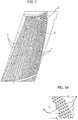
- each of the components 2, 3, 4 provided on each side of the rear part of the motor car constitutes a component in itself, having a hollow structure made, for example, of sheet metal or of plastic material.
- the hollow structure of the component is, for example, clearly illustrated in Figure 4 for the component 2.
- the component 2 also has a plurality of internal diaphragms 2a.
- these internal diaphragms have been prearranged in a removable way within the component 2 to enable tests to be conducted on the efficiency of the system according to the invention, modifying the volume of the internal chamber of the component. In the embodiment in line with normal production, however, the internal diaphragms 2a are not envisaged.
- Each of the components 2, 3, 4 is rigidly connected to the remaining part of the structure of the motor vehicle.
- connection of one or more of the components 2, 3, 4 to the structure of the motor vehicle is removable to enable easy and fast replacement of the component with a similar component having, however, a different conformation of the system according to the invention in order to modify the characteristics of the aerodynamic field around the motor vehicle when it is travelling, according to what will be described in greater detail in what follows.
- each of the components 2, 3, 4 has a hollow structure delimited externally by a curved wall R that radiuses in a gradual way, i.e., without any corners, each side wall of the motor vehicle with the rear wall of the motor vehicle.
- the curved outer wall R of each component 2, 3, 4 has a distribution of holes or pores p both in an area of the aerodynamic field of the vehicle with higher relative pressure (in the case in point on the portion of the wall R that extends on one side of the motor vehicle) and in an area of the aerodynamic field of the vehicle with lower relative pressure (in the case in point on the portion of the wall R that extends on the rear part of the motor vehicle).
- the pores p are distributed in vertical strips f interspersed by non-porous surface portions.
- the portion of the holes p that extends in the area of the aerodynamic field of the vehicle with higher relative pressure - the front part of each wall R - on each side of the motor vehicle enables the part of the flow of air that laps the vehicle when it is travelling to enter the chamber of each component 2, 3, 4.
- the part of the pores or holes p that extends in the area of the aerodynamic field of the vehicle with higher relative pressure - the rear portion of each wall R - on the rear side of the motor vehicle enables the flow of air that has entered the chamber to exit again, thus generating jets of air of a passive type (i.e., generated simply as a result of the movement of the motor vehicle, without any need for providing any active generator) that modify the aerodynamic field around the motor vehicle.
- the above phenomenon is exploited for predetermining the area of the radiusing wall R where the boundary layer of the air that laps the vehicle when it is travelling detaches from the motor-vehicle body, thus forming the wake.
- the chamber defined within the hollow structure of the component (2, 3, 4 in the example described) must have a minimum thickness (which the person skilled in the field may choose on the basis of tests) in order to be able to process a flow of air sufficient for operation of the system in the range of the normal speeds of advance of a motor vehicle.
- the system according to the invention is obtained by providing the porous radiusing surface R on an independent component 2 and/or 3 and/or 4 of the motor vehicle, it is also possible to replace the component that was originally provided with this component in order to modify in a desired way the aerodynamic characteristics of the motor vehicle.
- This aspect may be particularly advantageous, for example, in racing cars, where it may be required to modify the aerodynamic characteristics of the motor vehicle according to the circuit on which the car has to compete.
- Figure 5 is a cross-sectional view in a horizontal plane, according to the line VI-VI of Figure 1 .
- Figure 5 shows the aerodynamic field in a motor vehicle of the type illustrated in Figure 1 that is not equipped with the system according to the invention
- Figure 6 shows the result of application of the invention.
- the rear area to the motor vehicle has been divided into areas identified approximately with one and the same pressure value.
- application of the invention enables passage from a configuration of the type illustrated in Figure 5 to the configuration illustrated in Figure 6 where there is even created an area with negative values (corresponding to a thrust of the air against the rear part of the motor vehicle in the rear area of the latter (in the figures the arrow A indicates the direction of advance of the motor vehicle).
- Figures 7 and 8 are cross sections according to the line VII-VII of Figure 1 .
- Figure 7 regards again the aerodynamic field in the case of a car not equipped with the system according to the invention, whereas Figure 8 shows the result obtained by applying the system according to the invention. Also in this case the area involved in negative pressure values is increased, with a consequent considerable reduction of the aerodynamic drag of the motor vehicle.
- the criterion of choice of the sections for inlet and outlet of the air on the basis of the pressure values of the aerodynamic field of the motor vehicle enables application of the system also to other portions of the motor vehicle itself, without limitation to the one illustrated by way of example in the description.
- These portions may include, for example, a rear spoiler, the front and rear wheel housings of the vehicle, the underbody, and in general any part of the vehicle that is subject to a relative-pressure gradient of the aerodynamic field and that may be built as described for the component 2, 3, or 4.
- This moreover makes it possible to avoid providing air intakes or other flow ducts that have the function of carrying the air into the chamber of the component (2, 3, 4 in the example described, or any further component defining the system), which would be decidedly unattractive.
- the chamber within the component with a non-constant section, introducing locally restrictions of section (for example, with profiling of the walls of the chamber) that might induce variations of speed of the air within the chamber.
Landscapes
- Engineering & Computer Science (AREA)
- Chemical & Material Sciences (AREA)
- Combustion & Propulsion (AREA)
- Transportation (AREA)
- Mechanical Engineering (AREA)
- Physics & Mathematics (AREA)
- Fluid Mechanics (AREA)
- Body Structure For Vehicles (AREA)
Claims (3)
- System zum Steuern des aerodynamischen Widerstandes eines Kraftfahrzeugs, indem eine Ablösung der Grenzschicht in einem vorbestimmten Bereich eines Teils der Kraftfahrzeugkarosserie bewirkt wird, wobei das System mindestens eine Komponente des Aufbaus des Kraftfahrzeugs aufweist, die ein mit dem Aufbau starr verbundenes, getrenntes Element bildet,wobei die Komponente eine Außenwand des Kraftfahrzeugs definiert, wobei die Außenwand (R) mit einer regelmäßigen Verteilung von Poren (p) porös gemacht ist, und wobei die poröse Außenwand (R) eine in der Komponente (2, 3, 4) des Aufbaus des Kraftfahrzeugs enthaltene Kammer von außen abschließt, derart, dass, wenn das Kraftfahrzeug fährt, ein in einem Bereich des aerodynamischen Feldes des Fahrzeugs mit höherem relativen Druck gelegener, erster Teil der Poren (p) es ermöglicht, dass ein Teil des Luftstroms, der das Fahrzeug umhüllt, in die Kammer eintritt, während ein in einem Bereich des aerodynamischen Feldes des Fahrzeugs mit niedrigerem relativen Druck gelegener Teil der Poren (p) als Auslass für den Luftstrom von der oben genannten Kammer zu der Außenseite des Fahrzeugs hin funktioniert, derart, dass Luftstrahlen erzeugt werden, die eine Ablösung der Grenzschicht bewirken,die Position der in einem Bereich des aerodynamischen Feldes des Fahrzeugs mit niedrigerem relativen Druck gelegenen Poren (p) auf der porösen Außenwand (R) so gewählt ist, um Ablösung der Grenzschicht in einem gewünschten Bereich zu bestimmen,dadurch gekennzeichnet, dassdie Komponente eine gewölbte Außenwand des Kraftfahrzeugs definiert, die eine jeweilige Seite des Kraftfahrzeugs mit der Rückwand des Kraftfahrzeugs ohne Ecken abrundet,wobei das System eine Anzahl von Komponenten (2, 3, 4) umfasst, die jeweils mit der gewölbten porösen Wand (R) und mit der inneren Kammer hergestellt sind, wobei eine der Komponenten (2) zumindest einen Teil der senkrechten C-Stütze des Kraftfahrzeugs bildet, und die anderen Komponenten die Außenfläche des Kraftfahrzeugs unterhalb der senkrechten C-Stütze definieren,wobei die oben erwähnte gewölbte, abrundende Wand (R) und der Bereich der Wand, in dem eine Ablösung der Grenzschicht bewirkt wird, derart gewählt sind, um das Luftvolumen unmittelbar hinter dem Kraftfahrzeug mit einem Druck zu erhöhen, der darauf hinausläuft, das Kraftfahrzeug in die Vortriebsrichtung zu schieben.
- System nach Anspruch 1, wobei die Poren (p) in vertikalen Streifen (F) parallel und im Abstand voneinander verteilt sind.
- Kraftfahrzeug, dadurch gekennzeichnet, dass es mit einem System nach einem der vorhergehenden Ansprüche versehen ist.
Priority Applications (2)
| Application Number | Priority Date | Filing Date | Title |
|---|---|---|---|
| EP13185488.7A EP2851274B1 (de) | 2013-09-23 | 2013-09-23 | System zum Steuern des aerodynamischen Widerstands eines Kraftfahrzeuges, angepasst, um durch die Verwendung von passiven Düsen die Trennung der Grenzschicht an einem vorbestimmten Bereich der Kraftfahrzeugkarosserie zu bewirken, und Kraftfahrzeug mit einem solchem System |
| US14/452,098 US9359017B2 (en) | 2013-09-23 | 2014-08-05 | System for controlling the aerodynamic drag of a motor vehicle, designed to cause detachment of the boundary layer in a predetermined area of the motor-vehicle body, using passive jets, and motor vehicle equipped with this system |
Applications Claiming Priority (1)
| Application Number | Priority Date | Filing Date | Title |
|---|---|---|---|
| EP13185488.7A EP2851274B1 (de) | 2013-09-23 | 2013-09-23 | System zum Steuern des aerodynamischen Widerstands eines Kraftfahrzeuges, angepasst, um durch die Verwendung von passiven Düsen die Trennung der Grenzschicht an einem vorbestimmten Bereich der Kraftfahrzeugkarosserie zu bewirken, und Kraftfahrzeug mit einem solchem System |
Publications (2)
| Publication Number | Publication Date |
|---|---|
| EP2851274A1 EP2851274A1 (de) | 2015-03-25 |
| EP2851274B1 true EP2851274B1 (de) | 2016-07-06 |
Family
ID=49515159
Family Applications (1)
| Application Number | Title | Priority Date | Filing Date |
|---|---|---|---|
| EP13185488.7A Active EP2851274B1 (de) | 2013-09-23 | 2013-09-23 | System zum Steuern des aerodynamischen Widerstands eines Kraftfahrzeuges, angepasst, um durch die Verwendung von passiven Düsen die Trennung der Grenzschicht an einem vorbestimmten Bereich der Kraftfahrzeugkarosserie zu bewirken, und Kraftfahrzeug mit einem solchem System |
Country Status (2)
| Country | Link |
|---|---|
| US (1) | US9359017B2 (de) |
| EP (1) | EP2851274B1 (de) |
Families Citing this family (2)
| Publication number | Priority date | Publication date | Assignee | Title |
|---|---|---|---|---|
| US9950751B2 (en) * | 2015-09-25 | 2018-04-24 | GM Global Technology Operations LLC | Aerodynamic system and method for diagnosing the aerodynamic system and verify downforce estimation based on electric motor current |
| CN112208748B (zh) * | 2020-10-13 | 2022-10-11 | 中国人民解放军国防科技大学 | 一种主被动组合的超高速边界层转捩宽频控制方法 |
Family Cites Families (9)
| Publication number | Priority date | Publication date | Assignee | Title |
|---|---|---|---|---|
| FR1512563A (fr) * | 1966-12-29 | 1968-02-09 | Renault | Dispositif pour réduire la résistance à l'avancement des véhicules automobiles |
| US4343506A (en) * | 1980-08-05 | 1982-08-10 | The United States Of America As Represented By The Administrator Of The National Aeronautics And Space Administration | Low-drag ground vehicle particularly suited for use in safely transporting livestock |
| US4881772A (en) * | 1988-10-11 | 1989-11-21 | Feinberg Lee N | Rear-window wind deflector for a vehicle |
| DE3837729A1 (de) * | 1988-11-07 | 1990-05-10 | Dieter Prof Dr Ing Geropp | Verfahren und vorrichtung zum reduzieren des stroemungswiderstandes im heckbereich eines fahrzeugs, z. b. eines strassen- oder schienenfahrzeugs oder dergleichen |
| JP3549162B2 (ja) * | 1990-06-18 | 2004-08-04 | 本田技研工業株式会社 | 自動2輪車用フェアリング |
| US6616218B2 (en) | 1994-10-19 | 2003-09-09 | The United States Of America As Represented By The Administrator Of The National Aeronautics And Space Administration | Base passive porosity for vehicle drag reduction |
| FR2890637B1 (fr) * | 2005-09-12 | 2009-04-03 | Peugeot Citroen Automobiles Sa | Dispositif pour reduire les efforts aerodynamiques de trainee et/ou de portance d'un vehicule automobile equipe d'un tel dispositif. |
| FR2930229B1 (fr) * | 2008-04-16 | 2010-09-03 | Renault Sas | Agencement d'un dispositif de generation d'au moins un jet de gaz sur une carrosserie de vehicule automobile |
| JP5461162B2 (ja) * | 2009-12-07 | 2014-04-02 | 本田技研工業株式会社 | 鞍乗り型車両の後部構造 |
-
2013
- 2013-09-23 EP EP13185488.7A patent/EP2851274B1/de active Active
-
2014
- 2014-08-05 US US14/452,098 patent/US9359017B2/en active Active
Also Published As
| Publication number | Publication date |
|---|---|
| US9359017B2 (en) | 2016-06-07 |
| US20150084371A1 (en) | 2015-03-26 |
| EP2851274A1 (de) | 2015-03-25 |
Similar Documents
| Publication | Publication Date | Title |
|---|---|---|
| EP3344484B1 (de) | Modifizierung der aerodynamischen leistung eines fahrzeugs | |
| US9669807B2 (en) | Motor vehicle with ventilated wheel case | |
| EP3656652B1 (de) | Aerodynamische vorrichtung für fahrzeug | |
| EP1544089B1 (de) | Kraftfahrzeug mit einer Kontrollanlage für die aerodynamische Strömung, mittels synthetischen Jets | |
| US9221390B1 (en) | Aerodynamic mudflap with lighting element | |
| WO2016020423A1 (en) | Vehicle aerodynamic apparatus | |
| CN108216392B (zh) | 用于车辆的气流管理系统 | |
| US10144378B2 (en) | Vehicle air dam structure, and methods of use and manufacture thereof | |
| CN106005060B (zh) | 车辆用空气动力结构 | |
| US9359017B2 (en) | System for controlling the aerodynamic drag of a motor vehicle, designed to cause detachment of the boundary layer in a predetermined area of the motor-vehicle body, using passive jets, and motor vehicle equipped with this system | |
| CN109204585B (zh) | 汽车空气动力学车身底部装置 | |
| CN107010123B (zh) | 车轮罩结构 | |
| JP7765928B2 (ja) | 車体の下面に方向性パターンのシボ加工面を有する車両、および、車両のアンダカバー部材 | |
| US10457341B2 (en) | Underbody channel vortex generators | |
| CN106660600B (zh) | 具有共同承载式护板的马达驱动的单轮辙机动车 | |
| CN109018033B (zh) | 带空气动力学形状翼型截面的汽车行李箱盖扰流板 | |
| CN117048725A (zh) | 一种汽车隐藏式尾部扩散结构 | |
| SE538862C2 (sv) | Metod och kommersiellt fordon innefattande omdirigeringsmedel för luftflöde | |
| JP2008247146A (ja) | 車両用インナーフェンダ | |
| JP2014226953A (ja) | ホイル内駆動ユニットの冷却構造 | |
| KR20170069557A (ko) | 차량용 언더커버 | |
| Yang et al. | Center floor undercover air guide development to improve aerodynamic drag for a passenger car | |
| PL241707B1 (pl) | Urządzenie i sposób ograniczania oporu aerodynamicznego, zwłaszcza pojazdów | |
| Ravelli et al. | An overview of drag reduction methods in road cars | |
| GB2560321A (en) | Engine undercover |
Legal Events
| Date | Code | Title | Description |
|---|---|---|---|
| PUAI | Public reference made under article 153(3) epc to a published international application that has entered the european phase |
Free format text: ORIGINAL CODE: 0009012 |
|
| 17P | Request for examination filed |
Effective date: 20140804 |
|
| AK | Designated contracting states |
Kind code of ref document: A1 Designated state(s): AL AT BE BG CH CY CZ DE DK EE ES FI FR GB GR HR HU IE IS IT LI LT LU LV MC MK MT NL NO PL PT RO RS SE SI SK SM TR |
|
| AX | Request for extension of the european patent |
Extension state: BA ME |
|
| 17Q | First examination report despatched |
Effective date: 20150717 |
|
| GRAP | Despatch of communication of intention to grant a patent |
Free format text: ORIGINAL CODE: EPIDOSNIGR1 |
|
| INTG | Intention to grant announced |
Effective date: 20160226 |
|
| GRAS | Grant fee paid |
Free format text: ORIGINAL CODE: EPIDOSNIGR3 |
|
| GRAA | (expected) grant |
Free format text: ORIGINAL CODE: 0009210 |
|
| AK | Designated contracting states |
Kind code of ref document: B1 Designated state(s): AL AT BE BG CH CY CZ DE DK EE ES FI FR GB GR HR HU IE IS IT LI LT LU LV MC MK MT NL NO PL PT RO RS SE SI SK SM TR |
|
| REG | Reference to a national code |
Ref country code: GB Ref legal event code: FG4D |
|
| REG | Reference to a national code |
Ref country code: AT Ref legal event code: REF Ref document number: 810482 Country of ref document: AT Kind code of ref document: T Effective date: 20160715 Ref country code: CH Ref legal event code: EP |
|
| REG | Reference to a national code |
Ref country code: IE Ref legal event code: FG4D |
|
| REG | Reference to a national code |
Ref country code: DE Ref legal event code: R096 Ref document number: 602013009078 Country of ref document: DE Ref country code: FR Ref legal event code: PLFP Year of fee payment: 4 |
|
| REG | Reference to a national code |
Ref country code: NL Ref legal event code: MP Effective date: 20160706 |
|
| REG | Reference to a national code |
Ref country code: LT Ref legal event code: MG4D |
|
| REG | Reference to a national code |
Ref country code: AT Ref legal event code: MK05 Ref document number: 810482 Country of ref document: AT Kind code of ref document: T Effective date: 20160706 |
|
| PG25 | Lapsed in a contracting state [announced via postgrant information from national office to epo] |
Ref country code: NO Free format text: LAPSE BECAUSE OF FAILURE TO SUBMIT A TRANSLATION OF THE DESCRIPTION OR TO PAY THE FEE WITHIN THE PRESCRIBED TIME-LIMIT Effective date: 20161006 Ref country code: RS Free format text: LAPSE BECAUSE OF FAILURE TO SUBMIT A TRANSLATION OF THE DESCRIPTION OR TO PAY THE FEE WITHIN THE PRESCRIBED TIME-LIMIT Effective date: 20160706 Ref country code: NL Free format text: LAPSE BECAUSE OF FAILURE TO SUBMIT A TRANSLATION OF THE DESCRIPTION OR TO PAY THE FEE WITHIN THE PRESCRIBED TIME-LIMIT Effective date: 20160706 Ref country code: HR Free format text: LAPSE BECAUSE OF FAILURE TO SUBMIT A TRANSLATION OF THE DESCRIPTION OR TO PAY THE FEE WITHIN THE PRESCRIBED TIME-LIMIT Effective date: 20160706 Ref country code: IS Free format text: LAPSE BECAUSE OF FAILURE TO SUBMIT A TRANSLATION OF THE DESCRIPTION OR TO PAY THE FEE WITHIN THE PRESCRIBED TIME-LIMIT Effective date: 20161106 Ref country code: LT Free format text: LAPSE BECAUSE OF FAILURE TO SUBMIT A TRANSLATION OF THE DESCRIPTION OR TO PAY THE FEE WITHIN THE PRESCRIBED TIME-LIMIT Effective date: 20160706 Ref country code: FI Free format text: LAPSE BECAUSE OF FAILURE TO SUBMIT A TRANSLATION OF THE DESCRIPTION OR TO PAY THE FEE WITHIN THE PRESCRIBED TIME-LIMIT Effective date: 20160706 |
|
| PG25 | Lapsed in a contracting state [announced via postgrant information from national office to epo] |
Ref country code: BE Free format text: LAPSE BECAUSE OF NON-PAYMENT OF DUE FEES Effective date: 20160706 Ref country code: LV Free format text: LAPSE BECAUSE OF FAILURE TO SUBMIT A TRANSLATION OF THE DESCRIPTION OR TO PAY THE FEE WITHIN THE PRESCRIBED TIME-LIMIT Effective date: 20160706 Ref country code: GR Free format text: LAPSE BECAUSE OF FAILURE TO SUBMIT A TRANSLATION OF THE DESCRIPTION OR TO PAY THE FEE WITHIN THE PRESCRIBED TIME-LIMIT Effective date: 20161007 Ref country code: PT Free format text: LAPSE BECAUSE OF FAILURE TO SUBMIT A TRANSLATION OF THE DESCRIPTION OR TO PAY THE FEE WITHIN THE PRESCRIBED TIME-LIMIT Effective date: 20161107 Ref country code: PL Free format text: LAPSE BECAUSE OF FAILURE TO SUBMIT A TRANSLATION OF THE DESCRIPTION OR TO PAY THE FEE WITHIN THE PRESCRIBED TIME-LIMIT Effective date: 20160706 Ref country code: ES Free format text: LAPSE BECAUSE OF FAILURE TO SUBMIT A TRANSLATION OF THE DESCRIPTION OR TO PAY THE FEE WITHIN THE PRESCRIBED TIME-LIMIT Effective date: 20160706 Ref country code: AT Free format text: LAPSE BECAUSE OF FAILURE TO SUBMIT A TRANSLATION OF THE DESCRIPTION OR TO PAY THE FEE WITHIN THE PRESCRIBED TIME-LIMIT Effective date: 20160706 Ref country code: SE Free format text: LAPSE BECAUSE OF FAILURE TO SUBMIT A TRANSLATION OF THE DESCRIPTION OR TO PAY THE FEE WITHIN THE PRESCRIBED TIME-LIMIT Effective date: 20160706 |
|
| REG | Reference to a national code |
Ref country code: DE Ref legal event code: R097 Ref document number: 602013009078 Country of ref document: DE |
|
| PG25 | Lapsed in a contracting state [announced via postgrant information from national office to epo] |
Ref country code: RO Free format text: LAPSE BECAUSE OF FAILURE TO SUBMIT A TRANSLATION OF THE DESCRIPTION OR TO PAY THE FEE WITHIN THE PRESCRIBED TIME-LIMIT Effective date: 20160706 Ref country code: MC Free format text: LAPSE BECAUSE OF FAILURE TO SUBMIT A TRANSLATION OF THE DESCRIPTION OR TO PAY THE FEE WITHIN THE PRESCRIBED TIME-LIMIT Effective date: 20160706 Ref country code: EE Free format text: LAPSE BECAUSE OF FAILURE TO SUBMIT A TRANSLATION OF THE DESCRIPTION OR TO PAY THE FEE WITHIN THE PRESCRIBED TIME-LIMIT Effective date: 20160706 |
|
| REG | Reference to a national code |
Ref country code: CH Ref legal event code: PL |
|
| PLBE | No opposition filed within time limit |
Free format text: ORIGINAL CODE: 0009261 |
|
| STAA | Information on the status of an ep patent application or granted ep patent |
Free format text: STATUS: NO OPPOSITION FILED WITHIN TIME LIMIT |
|
| PG25 | Lapsed in a contracting state [announced via postgrant information from national office to epo] |
Ref country code: SM Free format text: LAPSE BECAUSE OF FAILURE TO SUBMIT A TRANSLATION OF THE DESCRIPTION OR TO PAY THE FEE WITHIN THE PRESCRIBED TIME-LIMIT Effective date: 20160706 Ref country code: DK Free format text: LAPSE BECAUSE OF FAILURE TO SUBMIT A TRANSLATION OF THE DESCRIPTION OR TO PAY THE FEE WITHIN THE PRESCRIBED TIME-LIMIT Effective date: 20160706 Ref country code: SK Free format text: LAPSE BECAUSE OF FAILURE TO SUBMIT A TRANSLATION OF THE DESCRIPTION OR TO PAY THE FEE WITHIN THE PRESCRIBED TIME-LIMIT Effective date: 20160706 Ref country code: CZ Free format text: LAPSE BECAUSE OF FAILURE TO SUBMIT A TRANSLATION OF THE DESCRIPTION OR TO PAY THE FEE WITHIN THE PRESCRIBED TIME-LIMIT Effective date: 20160706 Ref country code: BG Free format text: LAPSE BECAUSE OF FAILURE TO SUBMIT A TRANSLATION OF THE DESCRIPTION OR TO PAY THE FEE WITHIN THE PRESCRIBED TIME-LIMIT Effective date: 20161006 |
|
| 26N | No opposition filed |
Effective date: 20170407 |
|
| REG | Reference to a national code |
Ref country code: IE Ref legal event code: MM4A |
|
| PG25 | Lapsed in a contracting state [announced via postgrant information from national office to epo] |
Ref country code: IE Free format text: LAPSE BECAUSE OF NON-PAYMENT OF DUE FEES Effective date: 20160923 Ref country code: CH Free format text: LAPSE BECAUSE OF NON-PAYMENT OF DUE FEES Effective date: 20160930 Ref country code: LI Free format text: LAPSE BECAUSE OF NON-PAYMENT OF DUE FEES Effective date: 20160930 |
|
| PG25 | Lapsed in a contracting state [announced via postgrant information from national office to epo] |
Ref country code: SI Free format text: LAPSE BECAUSE OF FAILURE TO SUBMIT A TRANSLATION OF THE DESCRIPTION OR TO PAY THE FEE WITHIN THE PRESCRIBED TIME-LIMIT Effective date: 20160706 Ref country code: LU Free format text: LAPSE BECAUSE OF NON-PAYMENT OF DUE FEES Effective date: 20160923 |
|
| REG | Reference to a national code |
Ref country code: FR Ref legal event code: PLFP Year of fee payment: 5 |
|
| GBPC | Gb: european patent ceased through non-payment of renewal fee |
Effective date: 20170923 |
|
| PG25 | Lapsed in a contracting state [announced via postgrant information from national office to epo] |
Ref country code: HU Free format text: LAPSE BECAUSE OF FAILURE TO SUBMIT A TRANSLATION OF THE DESCRIPTION OR TO PAY THE FEE WITHIN THE PRESCRIBED TIME-LIMIT; INVALID AB INITIO Effective date: 20130923 |
|
| PG25 | Lapsed in a contracting state [announced via postgrant information from national office to epo] |
Ref country code: MT Free format text: LAPSE BECAUSE OF NON-PAYMENT OF DUE FEES Effective date: 20160930 Ref country code: CY Free format text: LAPSE BECAUSE OF FAILURE TO SUBMIT A TRANSLATION OF THE DESCRIPTION OR TO PAY THE FEE WITHIN THE PRESCRIBED TIME-LIMIT Effective date: 20160706 Ref country code: MK Free format text: LAPSE BECAUSE OF FAILURE TO SUBMIT A TRANSLATION OF THE DESCRIPTION OR TO PAY THE FEE WITHIN THE PRESCRIBED TIME-LIMIT Effective date: 20160706 |
|
| PG25 | Lapsed in a contracting state [announced via postgrant information from national office to epo] |
Ref country code: GB Free format text: LAPSE BECAUSE OF NON-PAYMENT OF DUE FEES Effective date: 20170923 |
|
| REG | Reference to a national code |
Ref country code: FR Ref legal event code: PLFP Year of fee payment: 6 |
|
| PG25 | Lapsed in a contracting state [announced via postgrant information from national office to epo] |
Ref country code: AL Free format text: LAPSE BECAUSE OF FAILURE TO SUBMIT A TRANSLATION OF THE DESCRIPTION OR TO PAY THE FEE WITHIN THE PRESCRIBED TIME-LIMIT Effective date: 20160706 Ref country code: TR Free format text: LAPSE BECAUSE OF FAILURE TO SUBMIT A TRANSLATION OF THE DESCRIPTION OR TO PAY THE FEE WITHIN THE PRESCRIBED TIME-LIMIT Effective date: 20160706 |
|
| PGFP | Annual fee paid to national office [announced via postgrant information from national office to epo] |
Ref country code: DE Payment date: 20240820 Year of fee payment: 12 |
|
| PGFP | Annual fee paid to national office [announced via postgrant information from national office to epo] |
Ref country code: FR Payment date: 20240820 Year of fee payment: 12 |
|
| PGFP | Annual fee paid to national office [announced via postgrant information from national office to epo] |
Ref country code: IT Payment date: 20240820 Year of fee payment: 12 |