EP2849608B1 - Möbelmodul - Google Patents
Möbelmodul Download PDFInfo
- Publication number
- EP2849608B1 EP2849608B1 EP13722292.3A EP13722292A EP2849608B1 EP 2849608 B1 EP2849608 B1 EP 2849608B1 EP 13722292 A EP13722292 A EP 13722292A EP 2849608 B1 EP2849608 B1 EP 2849608B1
- Authority
- EP
- European Patent Office
- Prior art keywords
- furniture module
- height
- furniture
- extension body
- pedestal
- Prior art date
- Legal status (The legal status is an assumption and is not a legal conclusion. Google has not performed a legal analysis and makes no representation as to the accuracy of the status listed.)
- Not-in-force
Links
- NJPPVKZQTLUDBO-UHFFFAOYSA-N novaluron Chemical compound C1=C(Cl)C(OC(F)(F)C(OC(F)(F)F)F)=CC=C1NC(=O)NC(=O)C1=C(F)C=CC=C1F NJPPVKZQTLUDBO-UHFFFAOYSA-N 0.000 claims 11
- 238000009434 installation Methods 0.000 description 6
- 238000011161 development Methods 0.000 description 2
- 230000018109 developmental process Effects 0.000 description 2
- 230000002093 peripheral effect Effects 0.000 description 2
- 238000010008 shearing Methods 0.000 description 2
- 238000005253 cladding Methods 0.000 description 1
- 150000001875 compounds Chemical class 0.000 description 1
- 238000010276 construction Methods 0.000 description 1
- 230000003203 everyday effect Effects 0.000 description 1
- 230000001771 impaired effect Effects 0.000 description 1
- 230000000276 sedentary effect Effects 0.000 description 1
- 239000007787 solid Substances 0.000 description 1
Images





Classifications
-
- A—HUMAN NECESSITIES
- A47—FURNITURE; DOMESTIC ARTICLES OR APPLIANCES; COFFEE MILLS; SPICE MILLS; SUCTION CLEANERS IN GENERAL
- A47B—TABLES; DESKS; OFFICE FURNITURE; CABINETS; DRAWERS; GENERAL DETAILS OF FURNITURE
- A47B51/00—Cabinets with means for moving compartments up and down
-
- A—HUMAN NECESSITIES
- A47—FURNITURE; DOMESTIC ARTICLES OR APPLIANCES; COFFEE MILLS; SPICE MILLS; SUCTION CLEANERS IN GENERAL
- A47B—TABLES; DESKS; OFFICE FURNITURE; CABINETS; DRAWERS; GENERAL DETAILS OF FURNITURE
- A47B77/00—Kitchen cabinets
- A47B77/02—General layout, e.g. relative arrangement of compartments, working surface or surfaces, supports for apparatus
- A47B77/022—Work tops
-
- A—HUMAN NECESSITIES
- A47—FURNITURE; DOMESTIC ARTICLES OR APPLIANCES; COFFEE MILLS; SPICE MILLS; SUCTION CLEANERS IN GENERAL
- A47B—TABLES; DESKS; OFFICE FURNITURE; CABINETS; DRAWERS; GENERAL DETAILS OF FURNITURE
- A47B77/00—Kitchen cabinets
- A47B77/04—Provision for particular uses of compartments or other parts ; Compartments moving up and down, revolving parts
- A47B77/06—Provision for particular uses of compartments or other parts ; Compartments moving up and down, revolving parts for incorporating sinks, with or without draining boards, splash-backs, or the like
-
- A—HUMAN NECESSITIES
- A47—FURNITURE; DOMESTIC ARTICLES OR APPLIANCES; COFFEE MILLS; SPICE MILLS; SUCTION CLEANERS IN GENERAL
- A47B—TABLES; DESKS; OFFICE FURNITURE; CABINETS; DRAWERS; GENERAL DETAILS OF FURNITURE
- A47B2200/00—General construction of tables or desks
- A47B2200/0035—Tables or desks with features relating to adjustability or folding
- A47B2200/004—Top adjustment
- A47B2200/0042—Height and inclination adjustable desktop, either separately or simultaneously
-
- A—HUMAN NECESSITIES
- A47—FURNITURE; DOMESTIC ARTICLES OR APPLIANCES; COFFEE MILLS; SPICE MILLS; SUCTION CLEANERS IN GENERAL
- A47B—TABLES; DESKS; OFFICE FURNITURE; CABINETS; DRAWERS; GENERAL DETAILS OF FURNITURE
- A47B2200/00—General construction of tables or desks
- A47B2200/0035—Tables or desks with features relating to adjustability or folding
- A47B2200/004—Top adjustment
- A47B2200/0043—Inclination adjustable work top
-
- A—HUMAN NECESSITIES
- A47—FURNITURE; DOMESTIC ARTICLES OR APPLIANCES; COFFEE MILLS; SPICE MILLS; SUCTION CLEANERS IN GENERAL
- A47B—TABLES; DESKS; OFFICE FURNITURE; CABINETS; DRAWERS; GENERAL DETAILS OF FURNITURE
- A47B2220/00—General furniture construction, e.g. fittings
- A47B2220/0002—Adjustable furniture construction
- A47B2220/0013—Table or cupboards with upwardly concealable compartments
Definitions
- the invention relates to a furniture module according to the preamble of claim 1 and a device according to the preamble of claim 9.
- a device for height adjustment of a worktop of a kitchen furniture which has an actuator for the slidably mounted in a vertical guide worktop, wherein the guide arranged at a mutual distance, parallel guide columns, each of a supported on a supporting wall of a furniture body hollow section and a slidably mounted in this hollow profile support profile for the worktop, wherein the hollow sections of the paired guide columns are provided between them, extending in the direction of the depth of the worktop, common support walls of the furniture body are supported and wherein the worktop for each pair of columns with the hollow profiles Support walls enclosing cladding.
- a kitchen work unit which comprises a kitchen cabinet with side walls, rear wall and doors, in which a lower guide column and an upper guide column is arranged, wherein the upper guide column is guided vertically adjustable on the lower guide column and carries on support profiles a worktop.
- a kitchen work unit known in which a worktop rests as a boom on an approximately V-shaped support arm, wherein the support arm is connected to a vertical column, which is guided in height adjustable in a lower guide column.
- the US 5,461,974 A describes a workstation with an integrated computer, the workstation is height adjustable and a worktop is tilted.
- the US 5,339,750 A teaches a height-adjustable work table.
- the invention has for its object to design a height-adjustable furniture module with boom so that it can be optimally integrated into a modular device and that this particular in any orientation about a vertical axis in a modular device can be integrated and that this meets high safety requirements.
- the furniture module according to the invention for a kitchen and / or a bathroom comprises a base body, a telescopic box, a boom body and a lifting device, wherein the base body is formed as a cuboid component of the furniture module having an interior, wherein the boom body is formed as a cuboid component of the furniture module housing, wherein the lifting device between the base body and the armature body is arranged, wherein the lifting device at least partially passes through the telescopic box, wherein the lifting device moves the boom body upwards and downwards relative to the base body, wherein between the first lifting device and the Boom body is arranged a fitting device, wherein the boom body with the help of the fitting device relative to the lifting device in a horizontal plane displaceable is and / or wherein the boom body with the aid of the fitting device relative to the lifting device by at least one, preferably two and in particular three orthogonal spatial axes is pivotable.
- the invention provides to connect the telescopic box with the boom body and to move by the lifting device together with the boom body, wherein the telescopic box is guided vertically movable from the base body and in particular in the base body.
- a compound of the three mutually occluding or guided into each other solid body is formed between a boom body and the telescopic box comprehensive lifting unit and a base unit comprehensive the base body an all-round enclosed space in which the lifting device is added.
- a covering of the lifting device is guaranteed in all positions of the furniture module, so that in everyday use, regardless of the installation orientation dangerous access to the lifting device is effectively prevented.
- the invention also provides to blind the boom body forward, to the sides and to the rear or to blind the boom body at its rear. As a result, an access protection to an interior of the furniture module is also given if the furniture module is installed in such a way that this does not face a wall with its rear side.
- the invention also provides to conceal the telescopic box and / or the base box forward, to the sides and in particular to the rear.
- a free-standing installation of the furniture module is also possible without undesired access to its interior space being possible.
- the invention provides a connection of the base body, in which the base body with the lifting device installed therein is connected either as a freestanding base exclusively to a floor of a room in which the furniture module is arranged, or as a wall-hung base exclusively with a wall a room, in which the furniture module is arranged, is connected or connected to a floor and a wall of a room in which the furniture module is arranged, or floor connected to a wall of a room in which the furniture module is arranged, or floorstanding connected to a cheek of a neighboring furniture module.
- the invention also provides to form the boom body of the furniture module with appropriate width and depth.
- a mobility of the boom body in which it is movable such that its upper side in a lower position as a work surface, in particular in a height of 50 cm to 120 cm and preferably from 73 cm to 107 cm can be used.
- the work surface is suitable both for a seated, ergonomic aspects corresponding work of children, adolescents and adults as well as for a standing, ergonomic aspects appropriate work of children, adolescents and adults.
- adjacent furniture modules without lifting function of the boom body of the furniture module according to the invention in its height is such that it does not over in its uppermost position with its peripheral lower edge a level of the top of the adjacent, adjacent Furniture module drives out.
- a danger of shearing is avoided even in an extreme position of the furniture module according to the invention and this regardless of whether the or the adjacent furniture modules without lift function on the left and / or right and / or behind the furniture module according to the invention are arranged.
- the invention provides to equip the furniture module with a receiving space, a shelf body and a second lifting device, wherein the receiving space is accessible through an opening in a top or the working surface of the boom body, wherein the shelf body completely received in a lowermost position in the receiving space and wherein the shelf body is in an uppermost position on an upper side of the boom body, wherein the second lifting device is arranged in particular under or next to the shelf body and in particular between the shelf body and the telescopic box or between the shelf body and the base body.
- the second lifting device By a lateral arrangement of the second lifting device with respect to the entering into the furniture module shelf body and high shelves can be integrated into the furniture module.
- it is provided in particular to arrange the second lifting device as viewed from the user's left and / or right or in front of the shelf body.
- a second lifting device arranged below the shelf body has the advantage that it allows a particularly compact installation, since the lifting device, viewed from above, requires no installation space which lies laterally next to the shelf body.
- the first lifting device which preferably comprises two components arranged close to the side cheeks, so that the shelf body and the second lifting device can be integrated into the free space of the furniture module present in the interior.
- the kitchen or bathroom comprises at least one height-adjustable furniture module according to at least one of the preceding claims and comprises the kitchen or bathroom at least one Bibnunver selectedbares furniture module.
- the invention provides to arrange the or one of the height-adjustable furniture modules between two essentiallynunver primary magnesium furniture modules and / or connect the or one of the height-adjustable furniture modules with a back to a cheek page of Essentiallynunver primarybaren furniture module, wherein the telescoping furniture module on the Essentiallynunver primarybaren furniture module and / or on a Wall is attached to which the Essentiallynunver Sbaren furniture module with its back.
- a cuboid component of a furniture module which has an interior, is understood to mean a body.
- a height-adjustable or height-adjustable furniture module is understood to mean a telescopic furniture module whose height can be changed by means of an electromechanical or electropneumatic lifting device.
- the FIG. 1 shows a front view of a first device 1 according to the invention, which is designed as a kitchen device 2 and a first inventive, height-adjustable furniture module 3 and a HANnunver basicbares furniture module 4 includes.
- the Almostnunver selectedbare furniture module 4 is designed as a two-door cabinet 5.
- the height-adjustable furniture module 3 comprises a base body 6, a telescopic box 7, a boom body 8, a lifting device 9 and a fitting device 10.
- the furniture module 3 is shown transparent with respect to the lifting device 9 and the fitting device 10.
- In the FIG. 1 is a work surface 11 and a top 12 of the furniture module 3 at a mean height H11.1.
- the furniture module 3 connects in the illustrated kitchen device to a side wall 13 of the cabinet 5, where it is facing this side wall 13 with a rear side 14.
- the fitting device 10 makes it possible to adjust the boom body 8 in a plane defined by the work surface 11 E11 and, for example, in an arrow z to move closer to the furniture module 4 to a gap S1 between the back 14 of the boom body 8 and the side cheek 13 of the Set furniture module 4 to a typical for the device 1 gap.
- the telescopic box 7, which is connected to the boom body 8, is also moved slightly ago, with a game with which the telescopic box 7 is guided in the base body 6, is dimensioned such that the telescopic box 7 is still easily moved when lifting and lowering , According to an embodiment variant, not shown, it is also intended, in particular for larger adjustment paths, to decouple the telescopic box 7 from the boom body 8 and after the adjustment of the boom body 8 via the fitting device 10 the Telescope box 7 slightly offset back to the boom body 8 to attach.
- FIG. 2 is a side view of those in the FIG. 1 shown kitchen device 2 shown, wherein the side view according to a FIG. 1 drawn arrow II is executed.
- the height-adjustable furniture module 3 has a width B3, which corresponds to a depth T4 of the height-adjustable furniture module 4.
- the fitting 10 allows a pivoting of the boom body 8 by three spatial axes.
- the boom body 8 is not only pivotable about the spatial axes Dx and Dy described above, but also about a spatial axis Dz.
- the space axis Dz runs in the FIG. 2 as a horizontal axis in the plane of the drawing and the boom body 8 is pivotable about these in the directions wz to the right and wz 'to the left.
- the adjustment described, which provides the fitting device 10, allow the boom body 8 in its spatial orientation in such a way to adapt to adjacent furniture modules that both a horizontal alignment of the work surface 11 and uniform gaps to the adjacent furniture modules are available.
- FIG. 3 is a top view of the depiction of the FIG. 1 shown.
- the wall 15 of a kitchen 16 is still recognizable, to which the cabinet 5 with a rear side 17 and at which the height-adjustable furniture module 3 is present with a right side wall 18.
- FIGS. 4 and 5 is that from the FIGS. 1 to 3 known first height-adjustable furniture module 3 shown in two perspective views.
- the working surface 11 of the furniture module 3 in the FIG. 4 in a height H11.2 and in the FIG. 5 at a height H11.3.
- the height H11.2 corresponds to the lowest height, which can occupy the working surface 11
- the height H11.3 corresponds to the highest height, which can occupy the working surface 11.
- the in the FIG. 1 shown height H11.1 lies between these two heights.
- the boom body 8 moves together with the telescopic box 7, wherein the base body 6 remains in an unchanged position on a floor 20.
- the boom body 8 and the telescopic box 7 are connected to each other.
- the boom body 8 is formed as a closed body formed by a right cheek 8a, a left cheek 8b, a front cheek 8c, a rear wall 8d, the work surface 11 and a bottom 8e, with a bottom opening 21 (see FIG FIG. 1 ) is closed by the protruding into the boom body 8 telescopic box 7.
- FIG. 6 a second device 22 according to the invention is shown, which comprises the FIGS. 1 to 5 known, first height-adjustable furniture module 3 and designed as a cabinet 23 Brununver auses furniture module 24 includes.
- the furniture module 3 is in its uppermost position S3.3. in the Comparing with a top 25 of the sub-cabinet 23 it can be seen that the boom body 8 is located with a peripheral lower edge 26 at a height H26, which is less than a height H23 of the upper side 25 of the lower cabinet 23. This effectively prevents the boom body 8 of the upper side 25 of the lower cabinet 23 can be engaged by a user.
- an interior space 27 of the furniture module 3 is encapsulated on all sides to the outside, so that no access to the lifting device 9 and the fitting device 10 is possible for a user.
- an access to the interior 27 is also not possible from the back 14, since the boom body 8 is closed here by the rear cheek 8d.
- FIG. 7 is a back view of that in the FIG. 6 shown height-adjustable furniture module 3 shown.
- the lifting device 9 substantially comprises two lifting components 9a, 9b, which are arranged adjacent to the right cheek 8a and the left cheek 8b of the boom body 8, so that between the two lifting components 9a, 9b in the interior 27 of Furniture module 3, a free space 28 remains, which is schematically bounded by a dash-dotted lines.
- the fitting device 10 which is arranged between the lifting device 9 and the boom body 8 it is possible the boom body 8 in a horizontal plane in the x and x 'direction to the left and right and in the z and z' direction front and back (see FIG. 6 ).
- FIG. 8 is a perspective view of a third device 29 according to the invention shown, which is designed as L-kitchen 30.
- the device 29 comprises a second inventive, height-adjustable furniture module 31, which is designed as a height-adjustable sink 32, and a third inventive, height-adjustable furniture module 33, which is designed as a height-adjustable stove 34.
- the sink 32 is disposed below upper cabinets 35, 36 between a left lower cabinet 37 and a right lower cabinet 38.
- the furniture module 31 can be moved from an illustrated middle position S31.1 into a lower position S31.2 and an upper position S31.3 and any intermediate positions.
- the hearth 34 is movable in a comparable manner.
- FIG. 9 a fourth device 39 according to the invention is shown, which is designed as a kitchen island 40.
- a fixed section 42 of the kitchen island 40 is formed by four height-adjustable furniture modules 43, 44, 45, 46 and a plate 47 which covers them together.
- the furniture module 41 is movable with its work surface 48 from a shown middle position S41.1 in a lower position S41.2 and an upper position S41.3.
- a fifth device 49 according to the invention is shown, which is designed as L-kitchen 50.
- the device 49 comprises a fifth height-adjustable furniture module 51 according to the invention, which is designed as a height-adjustable sink 52, and a sixth height-adjustable furniture module 53 according to the invention, which is designed as a height-adjustable table 54.
- the sink 52 is arranged between a left lower cabinet 55 and a right lower cabinet 56.
- a sixth device 57 which is designed as an L-kitchen 58.
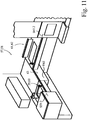
- the device 57 comprises a seventh height-adjustable furniture module 59 according to the invention, which is designed as a height-adjustable sink 60, and an eighth one Inventive, height-adjustable furniture module 61, which is designed as a height-adjustable stove 62.
- a lower cabinet 63 is arranged between the sink 59 and the hearth 62, which has a height H63 which corresponds to a lowermost position S59.2 of the sink 60 and a lowermost position S61.2 of the oven 62. This creates a large area optimized for sedentary activity or small individuals.
- a seventh inventive device 64 is shown in various perspective views.
- the device 64 is designed as a kitchen island 65 and is composed of a ninth height-adjustable furniture module 66 and a fixed section 67, wherein the fixed section 67 is only partially shown.
- the furniture module 66 is designed as a table 68.
- the furniture module 66 comprises, in its working surface 69 forming a top side, an opening 70 which leads into a receiving space 71 of the furniture module 66 indicated by dashed lines.
- the furniture module 66 further comprises a shelf body 72 and a second lifting device 73, wherein the shelf body 72 from the illustrated, extended position S72.3 by means of the second lifting device 73 downwardly into the receiving space 71, which is formed in an interior 74 of the furniture module 66 , can be retracted that a topsoil 75 of the schematically shown shelf body 72 rests on the working surface 69.
- a first lifting device 76 which raises and lowers a boom body 77 of the furniture module 66 is indicated only schematically.
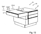
- the boom body 77 is in the FIG. 12 in its lowest position S66.2. In the FIG. 13 the boom body 77 is in a middle position S66.1, wherein the shelf body 72 is in a fully retracted position S72.2. In the FIG. 14 the boom body 77 is then in its uppermost position S66.3 and the shelf body 72 remains in its fully retracted position S72.2.
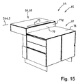
- FIG. 15 finally shows a rear view on the representation of FIG. 14 ,
- the boom body 77 of the height-adjustable furniture module 66 projects beyond a working surface 78 of the stationary section 67 of the kitchen island 65 in its uppermost position S66.3.
- the furniture module 66 and its boom body 77 is completely covered and protected on a back 79 by a rear cheek 77, so that it can be generated without dangerous shearing and without the overall impression is impaired, that is easily possible Furniture module 66 on the back of other furniture modules as example, the fixed section 67 connects and is moved in its height beyond this.
- FIGS. 16 to 18 An eighth device 80 according to the invention is shown in perspective views.
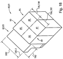
- the device 80 is designed as a kitchen island 81 and, in addition to a height-adjustable furniture module 82 according to the invention, which is designed as a table 83, a fixed portion 84.
- the fixed portion is optionally by four individual modules 85, 86, 87 and 88 or by two double modules 89th 90, which are covered by a common cover plate, not shown.
- a width B82 of the furniture module is adapted to a depth T85 to T88 or T89, T90 of the single or double modules 85 to 90 such that the width B82 corresponds to twice the depth.
- the furniture module 82 is shown in a middle position S82.1, in an uppermost position S82.3 and in a lowermost position S82.2.
- a depth T82 of the furniture module 82 corresponds to the depths T85 - T90 of the single or double modules 85 to 90, so that they can also be grouped together in series.
Landscapes
- Combinations Of Kitchen Furniture (AREA)
- Legs For Furniture In General (AREA)
Description
- Die Erfindung betrifft ein Möbelmodul gemäß dem Oberbegriff des Anspruchs 1 und eine Einrichtung gemäß dem Oberbegriff des Anspruchs 9.
- Aus der
DE 20 2008 006 655 U1 ist eine Vorrichtung zur Höhenverstellung einer Arbeitsplatte eines Küchenmöbels bekannt, welche einen Stellantrieb für die in einer vertikalen Führung verschiebbar gelagerte Arbeitsplatte aufweist, wobei die Führung in einem gegenseitigen Abstand angeordnete, parallele Führungssäulen umfasst, die jeweils aus einem an einer Stützwand eines Möbelkorpus abgestützten Hohlprofil und einem in diesem Hohlprofil verschiebbar gelagerten Tragprofil für die Arbeitsplatte bestehen, wobei die Hohlprofile der paarweise angeordneten Führungssäulen an zwischen ihnen vorgesehenen, in Richtung der Tiefe der Arbeitsplatte verlaufenden, gemeinsamen Stützwänden des Möbelkorpus abgestützt sind und wobei die Arbeitsplatte für jedes Säulenpaar eine die Hohlprofile mit den Stützwänden umschließende Verkleidung aufweist. - Aus der
DE 40 01 382 A1 ist eine Küchenarbeitseinheit bekannt, welche einen Küchenunterschrank mit Seitenwänden, Rückwand und Türen umfasst, in welchem eine untere Führungssäule und eine obere Führungssäule angeordnet ist, wobei die obere Führungssäule auf der unteren Führungssäule höhenverstellbar geführt ist und auf Tragprofilen eine Arbeitsplatte trägt. Weiterhin ist aus derDE 40 01 382 A1 eine Küchenarbeitseinheit bekannt, bei welcher eine Arbeitsplatte als Ausleger auf einem etwa V-förmigen Tragarm aufliegt, wobei der Tragarm mit einer vertikalen Säule verbunden ist, welche in einer unteren Führungssäule höhenverstellbar geführt ist. - Die
US 5,461,974 A beschreibt eine Workstation mit einem integrierten Computer, wobei die Workstation höhenverstellbar ist und eine Arbeitsplatte kippbar ist. - Aus der
US 2007/0261608 A1 ist eine Schreibtischanordnung bekannt, bei der die Arbeitsplatte höhenverstellbar und kippbar ist. - Die
US 5,339,750 A lehrt einen in der Höhe verstellbaren Arbeitstisch. - Aus der
US 2005/0275322 A1 ist eine Tischanordnung bekannt, die höhenverstellbar ist und bei der die Arbeitsplatte kippbar und in y-Richtung verfahrbar ist. - Der Erfindung liegt die Aufgabe zugrunde, ein höhenverstellbares Möbelmodul mit Ausleger so auszugestalten, dass dieses optimal in eine modular aufgebaute Einrichtung integrierbar ist und dass dieses insbesondere auch in beliebiger Orientierung um eine Hochachse in eine modular aufgebaute Einrichtung integrierbar ist und dass dieses hohen Sicherheitsanforderungen genügt.
- Diese Aufgabe wird ausgehend von den Merkmalen des Oberbegriffs des Anspruchs 1 bzw. 9 durch die kennzeichnenden Merkmale des Anspruchs 1 bzw. 9 gelöst. In den jeweiligen Unteransprüchen sind vorteilhafte und zweckmäßige Weiterbildungen angegeben.
- Das erfindungsgemäße Möbelmodul für eine Küche und/oder ein Bad umfasst einen Sockelkorpus, einen Teleskopkasten, einen Auslegerkorpus und eine Hubeinrichtung, wobei der Sockelkorpus als quaderförmiger Bestandteil des Möbelmoduls ausgebildet ist, der einen Innenraum aufweist, wobei der Auslegerkorpus als quaderförmiger Bestandteil des Möbelmoduls ausgebildet ist, der einen Innenraum aufweist, wobei die Hubeinrichtung zwischen dem Sockelkorpus und dem Auslegerkorpus angeordnet ist, wobei die Hubeinrichtung den Teleskopkasten zumindest teilweise durchläuft, wobei die Hubeinrichtung den Auslegerkorpus relativ zum dem Sockelkorpus nach oben und nach unten bewegt, wobei zwischen der ersten Hubeinrichtung und dem Auslegerkorpus eine Beschlageinrichtung angeordnet ist, wobei der Auslegerkorpus mit Hilfe der Beschlageinrichtung gegenüber der Hubeinrichtung in einer horizontalen Ebene verschiebbar ist und/oder wobei der Auslegerkorpus mit Hilfe der Beschlageinrichtung gegenüber der Hubeinrichtung um mindestens eine, vorzugsweise zwei und insbesondere drei orthogonale Raumachsen schwenkbar ist. Durch eine derartige Zwischenschaltung einer Beschlageinrichtung zwischen den Auslegerkorpus und die Hubeinrichtung ist es möglich, den Auslegerkorpus optimal auf benachbarte Möbelmodule auszurichten und ein einheitliches Spaltmaß zwischen den aneinander grenzenden Möbelmodulen einzustellen. Erst hierdurch wird es möglich, ein derartiges Möbelmodul so in eine Einrichtung aus einer Vielzahl von Möbelmodulen zu integrieren, dass das gewünschte einheitliche Erscheinungsbild entsteht, bei welchem das erfindungsgemäße Möbelmodul nicht auf den ersten Blick als Sondermodul auffällt, sondern zum Beispiel dann, wenn der Auslegerkorpus mit seiner Oberseite auf gleicher Höhe mit ein oder zwei benachbarten Möbelmodulen steht, tatsächlich eine durchgehende Ebene Fläche mit einheitlichen Spaltmaßen vorliegt. Kern der Erfindung ist somit ein Möbelmodul, welches mit der räumlichen Ausrichtung seiner Auslegerkorpus an benachbarte Küchenmodule anpassbar ist, um ein einheitliches Bild der Einrichtung zu ermöglichen.
- Weiterhin sieht die Erfindung vor, den Teleskopkasten mit dem Auslegerkorpus zu verbinden und durch die Hubeinrichtung zusammen mit dem Auslegerkorpus zu bewegen, wobei der Teleskopkasten von dem Sockelkorpus und insbesondere in dem Sockelkorpus vertikalbeweglich geführt ist. Durch eine derartige Verbindung der drei sich gegenseitig verschließenden bzw. ineinander geführten Volumenkörper entsteht zwischen einer den Auslegerkorpus und den Teleskopkasten umfassenden Hubeinheit und einer den Sockelkorpus umfassenden Standeinheit ein allseitig umschlossener Bauraum, in welchem die Hubeinrichtung aufgenommen ist. Bei einer derartigen Korpus- und Kastenbauweise ist eine Verkleidung der Hubeinrichtung in allen Stellungen des Möbelmoduls gewährleistet, so dass im Alltagsbetrieb unabhängig von der Einbauorientierung ein gefährlicher Zugriff auf die Hubeinrichtung wirksam verhindert ist.
- Die Erfindung sieht auch vor, den Auslegerkorpus nach vorne, zu den Seiten und nach hinten zu verblenden oder den Auslegerkorpus an seiner Rückseite zu verblenden. Hierdurch ist eine Zugriffsabsicherung auf einen Innenraum des Möbelmoduls auch dann gegeben, wenn das Möbelmodul derart verbaut ist, dass dieses mit seiner Rückseite nicht einer Wand gegenüberliegt.
- Die Erfindung sieht auch vor, den Teleskopkasten und/oder den Sockelkasten nach vorne, zu den Seiten und insbesondere nach hinten zu verblenden. Hierdurch ist zum Beispiel bei einer allseitigen Verblendung auch eine freistehende Aufstellung des Möbelmoduls möglich, ohne dass ein ungewünschter Zugriff auf dessen Innenraum möglich ist.
- Weiterhin sieht die Erfindung vor, eine Anbindung des Sockelkorpus vor, bei welcher der Sockelkorpus mit der darin verbauten Hubeinrichtung entweder als frei stehender Sockel ausschließlich mit einem Boden eines Raumes, in welchem das Möbelmodul angeordnet ist, verbunden ist oder als wandhängender Sockel ausschließlich mit einer Wand eines Raumes, in welchem das Möbelmodul angeordnet ist, verbunden ist oder mit einem Boden und einer Wand eines Raumes, in welchem das Möbelmodul angeordnet ist, verbunden ist oder bodenstehend mit einer Wand eines Raumes, in welchem das Möbelmodul angeordnet ist, verbunden ist oder bodenstehend mit einer Wange eines benachbarten Möbelmoduls verbunden ist. Hierdurch ist es möglich, das Möbelmodul in allen Einbausituationen optimal an ein Gebäude anzubinden.
- Die Erfindung sieht auch vor, den Auslegerkorpus des Möbelmoduls mit sich entsprechender Breite und Tiefe auszubilden. Durch eine derartige, in Draufsicht quadratische Ausbildung ist es möglich, das Möbelmodul auch um 90° gedreht als Endmodul in eine Möbelzeile zu integrieren, ohne dass dieses über das benachbarte Möbelmodul hinaus steht.
- Gemäß der Erfindung ist eine Verfahrbarkeit des Auslegerkorpus vorgesehen, bei welcher dieser derart verfahrbar ist, dass seine Oberseite in einer unteren Stellung als Arbeitsfläche, insbesondere in einer Höhe von 50 cm bis 120 cm und vorzugsweise von 73 cm bis 107 cm nutzbar ist. Hierdurch ist die Arbeitsfläche sowohl für ein sitzendes, ergonomischen Gesichtspunkten entsprechendes Arbeiten von Kindern, Jugendlichen und Erwachsenen als auch für ein stehendes, ergonomischen Gesichtspunkten entsprechendes Arbeiten von Kindern, Jugendlichen und Erwachsenen geeignet. Abhängig von den mit dem Möbelmodul für die Arbeitsplatte realisierbaren Verfahrhöhen und abhängig von einer Höhe einer Oberseite von angrenzenden, benachbarten Möbelmodulen ohne Hubfunktion ist der Auslegerkorpus des erfindungsgemäßen Möbelmoduls in seiner Höhe derart bemessen, dass dieser auch in seiner obersten Stellung mit seiner umlaufenden Unterkante nicht über ein Niveau der Oberseite des angrenzenden, benachbarten Möbelmoduls hinaus fährt. Hierdurch ist auch in einer Extremstellung des erfindungsgemäßen Möbelmoduls eine Gefahr durch Abscheren vermieden und dies unabhängig davon ob das bzw. die angrenzenden Möbelmodule ohne Hubfunktion links und/oder rechts und/oder hinter dem erfindungsgemäßen Möbelmodul angeordnet sind.
- Weiterhin sieht die Erfindung vor, das Möbelmodul mit einem Aufnahmeraum, einem Regalkorpus und einer zweiten Hubeinrichtung auszustatten, wobei der Aufnahmeraum durch eine Öffnung in einer Oberseite bzw. der Arbeitsfläche des Auslegerkorpus zugänglich ist, wobei der Regalkorpus in einer untersten Stellung vollständig in dem Aufnahmeraum aufgenommen ist und wobei der Regalkorpus in einer obersten Stellung über eine Oberseite des Auslegerkorpus hinaus steht, wobei die zweite Hubeinrichtung insbesondere unter oder neben dem Regalkorpus und insbesondere zwischen dem Regalkorpus und dem Teleskopkasten oder zwischen dem Regalkorpus und dem Sockelkorpus angeordnet ist. Hierdurch ist es möglich, das Möbelelement auch als Stauraum zu nutzen, wobei der Regalkorpus in seiner eingefahrenen Stellung derart in das Möbelelement aufgenommen ist, dass dem Nutzer die vollständige Arbeitsfläche des Möbelelements zur Verfügung steht. Durch eine seitliche Anordnung der zweiten Hubeinrichtung in Bezug auf den in das Möbelmodul einfahrenden Regalkorpus lassen sich auch hohe Regale in das Möbelmodul integrieren. Hierbei ist es insbesondere vorgesehen, die zweite Hubeinrichtung von Nutzer aus betrachtet links und/oder rechts oder vor dem Regalkorpus anzuordnen. Eine Unterhalb des Regalkorpus angeordnete zweite Hubeinrichtung hat den Vorteil, dass diese einen besonders kompakten Einbau ermöglicht, da die Hubeinrichtung von oben betrachtet keinen Bauraum benötigt, welcher seitlich neben dem Regalkorpus liegt. Hierdurch steht auch für die erste Hubeinrichtung, welche vorzugsweise zwei, nahe an den Seitenwangen angeordneten Komponenten umfasst, ausreichend Bauraum zur Verfügung, so dass sich der Regalkorpus und die zweite Hubeinrichtung in den im Innenraum vorhandenen Freiraum des Möbelmoduls integrieren lassen.
- Bei der erfindungsgemäßen Einrichtung, welche insbesondere als Kücheneinrichtung und/oder als Badeinrichtung ausgebildet ist, umfasst die Küche oder das Bad wenigstens ein höhenverstellbares Möbelmodul entsprechend wenigstens einem der vorhergehenden Ansprüche und umfasst die Küche oder das Bad wenigstens ein höhenunveränderbares Möbelmodul. Hierdurch entsteht eine multifunktionale Küche bzw. ein multifunktionale Bad, welches als Generationeneinrichtung sowohl von Kindern, Jugendlichen und Erwachsenen größen- und anforderungsgerecht nutzbar ist.
- Schließlich sieht die Erfindung vor, das oder eines der höhenverstellbaren Möbelmodule zwischen zwei höhenunveränderbaren Möbelmodulen anzuordnen und/oder das oder eines der höhenverstellbaren Möbelmodule mit einer Rückseite an eine Wangenseite eines höhenunveränderbaren Möbelmoduls anzuschließen, wobei das telesopierbare Möbelmodul an dem höhenunveränderbaren Möbelmodul und/oder an einer Wand befestigt ist, an welche das höhenunveränderbaren Möbelmodul mit seiner Rückseite steht. Hierdurch entsteht eine Einrichtung, welche gegenüber herkömmlichen Einrichtungen besser an individuelle Wünsche und Anforderungen anpassbar ist.
- Im Sinne der Erfindung wird unter einem Korpus ein quaderförmiger Bestandteil eines Möbelmoduls verstanden, welcher einen Innenraum aufweist.
- Im Sinne der Erfindung wird unter einem höhenverstellbaren bzw. höhenveränderbaren Möbelmodul ein teleskopierbares Möbelmodul verstanden, dessen Höhe mittels einer elektromechanischen oder elektropneumatischen Hubeinrichtung veränderbar ist.
- Weitere Einzelheiten der Erfindung werden in der Zeichnung anhand von schematisch dargestellten Ausführungsbeispielen beschrieben.
- Hierbei zeigt:
- Figur 1:
- eine Frontansicht einer ersten erfindungsgemäßen Einrichtung, welche ein erstes erfindungsgemäßes, höhenveränderbares Möbelmodul und ein höhenunveränderbares Möbelmodul umfasst;
- Figur 2:
- einen Ansicht von rechts auf die in der
Figur 1 gezeigte Einrichtung; - Figur 3:
- eine Ansicht von oben auf die in der
Figur 3 gezeigte Einrichtung; - Figuren 4
- und 5: das aus den
Figuren 1 bis 3 bekannten erste höhenverstellbare Möbelmodul in perspektivischen Ansichten; - Figur 6:
- eine zweite erfindungsgemäße Einrichtung, welche das aus den
Figuren 1 bis 5 bekannte, erste höhenverstellbare Möbelmodul und ein als Unterschrank ausgebildetes höhenunverstellbare Möbelmodul umfasst; - Figur 7:
- eine Rückansicht des in der
Figur 6 gezeigten höhenverstellbaren Möbelmoduls; - Figur 8:
- eine dritte erfindungsgemäße Einrichtung, welche als L-Küche ausgebildet ist;
- Figur 9:
- eine vierte erfindungsgemäße Einrichtung, welche als Kücheninsel ausgebildet ist;
- Figur 10:
- eine fünfte erfindungsgemäße Einrichtung, welche als L-Küche ausgebildet ist;
- Figur 11:
- eine sechste erfindungsgemäße Einrichtung, welche als L-Küche ausgebildet ist;
- Figur 12 -
- 15: eine siebte erfindungsgemäße Einrichtung, welche als Kücheninsel ausgebildet ist und eine zweites erfindungsgemäßen Küchenmodul, umfasst und
- Figur 16 - 18:
- eine achte erfindungsgemäße Einrichtung, welche als Kücheninsel ausgebildet ist und ein drittes erfindungsgemäßes Küchenmodul, umfasst.
- Die
Figur 1 zeigt eine Frontansicht einer ersten erfindungsgemäßen Einrichtung 1, welche als Kücheneinrichtung 2 ausgebildet ist und ein erstes erfindungsgemäßes, höhenveränderbares Möbelmodul 3 und ein höhenunveränderbares Möbelmodul 4 umfasst. Das höhenunveränderbare Möbelmodul 4 ist als zweitüriger Schrank 5 ausgeführt. Das höhenveränderbare Möbelmodul 3 umfasst einen Sockelkorpus 6, einen Teleskopkasten 7, einen Auslegerkorpus 8, eine Hubeinrichtung 9 und eine Beschlageinrichtung 10. Zum besseren Verständnis ist das Möbelmodul 3 in Bezug auf die Hubeinrichtung 9 und die Beschlageinrichtung 10 durchsichtig dargestellt. In derFigur 1 steht eine Arbeitsfläche 11 bzw. eine Oberseite 12 des Möbelmoduls 3 auf eine mittleren Höhe H11.1. Das Möbelmodul 3 schließt bei der dargestellten Kücheneinrichtung an eine Seitenwange 13 des Schrankes 5 an, wobei es dieser Seitenwange 13 mit einer Rückseite 14 zugewandt ist. Die Beschlageinrichtung 10 ermöglicht es, den Auslegerkorpus 8 in einer durch die Arbeitsfläche 11 definierten Ebene E11 zu verstellen und beispielsweise in eine Pfeilrichtung z näher an das Möbelmodul 4 zu schieben, um einen Spalt S1 zwischen der Rückseite 14 des Auslegerkorpus 8 und der Seitenwange 13 des Möbelmoduls 4 auf ein für die Einrichtung 1 typisches Spaltmaß einzustellen. Der Teleskopkasten 7, welcher mit dem Auslegerkorpus 8 verbunden ist, wird herbei ebenfalls leicht verschoben, wobei ein Spiel, mit welchem der Teleskopkasten 7 in dem Sockelkorpus 6 geführt ist, derart bemessen ist, dass der Teleskopkasten 7 beim Heben und Senken weiterhin leichtgängig verfahrbar ist. Gemäß einer nicht dargestellten Ausführungsvariante ist es insbesondere für größere Verstellwege auch vorgesehen, den Teleskopkasten 7 von dem Auslegerkorpus 8 zu entkoppeln und nach dem Verstellen des Auslegerkorpus 8 über die Beschlageinrichtung 10 den Teleskopkasten 7 leicht versetzt wieder an dem Auslegerkorpus 8 zu befestigen. Erfindungsgemäß ist es auch vorgesehen, den Auslegerkorpus mit Hilfe der Beschlagseinrichtung 10 um eine parallel zu der Rückseite 14 horizontal verlaufenden Drehachse Dx in Pfeilrichtungen wx nach unten bzw. wx' nach oben zu schwenken, um die Arbeitsfläche 11 waagrecht auszurichten. In derFigur 2 ist eine Seitenansicht auf die in derFigur 1 gezeigte Kücheneinrichtung 2 gezeigt, wobei die Seitenansicht entsprechend einem dieFigur 1 eingezeichneten Pfeil II ausgeführt ist. In der Seitenansicht ist erkennbar, dass das höhenverstellbare Möbelmodul 3 einen Breite B3 aufweist, welche einer Tiefe T4 des höhenunverstellbaren Möbelmoduls 4 entspricht. Zur weiteren Justierung der Arbeitsfläche 11 ist bevorzugt zusätzlich zu der Verschwenkbarkeit um die Drehachse Dx auch eine durch die Beschlageinrichtung 10 zur Verfügung gestellte Verschwenkbarkeit des Auslegerkorpus 8 um eine vertikal im Raum stehende Hochachse Dy vorgesehen (siehe auchFigur 3 ). Hierdurch ist in der dargestellten Einbausituation bei Bedarf beispielsweise ein einheitliches Spaltmaß zwischen einer Wand 15 und dem Auslegerkorpus 8 durch Schwenken des Auslegerkorpus 8 in ein Richtung wy bzw. wy' herstellbar. Bevorzugt ist es auch vorgesehen, dass die Beschlagseinrichtung 10 eine Schwenkbarkeit des Auslegerkorpus 8 um drei Raumachsen ermöglicht. Bei einer derartigen Beschlageinrichtung 10 ist der Auslegerkorpus 8 nicht nur um die oben beschriebenen Raumachsen Dx und Dy schwenkbar, sondern auch um eine Raumachse Dz. Die Raumachse Dz verläuft in derFigur 2 als horizontale Achse in die Zeichnungsebene hinein und der Auslegerkorpus 8 ist um diese in die Richtungen wz nach rechts und wz' nach links schwenkbar. Die beschriebenen Verstellmöglichkeiten, welche die Beschlageinrichtung 10 zur Verfügung stellt, ermöglichen es den Auslegerkorpus 8 in seiner räumlichen Ausrichtung derart auf benachbarte Möbelmodule abzupassen, dass sowohl ein waagrechte Ausrichtung der Arbeitsfläche 11 als auch einheitliche Spaltmaße zu den benachbarten Möbelmodulen vorhanden sind. - In der
Figur 3 ist eine Ansicht von oben auf die Darstellung derFigur 1 gezeigt. In dieser Ansicht ist weiterhin die Wand 15 einer Küche 16 erkennbar, an welcher der Schrank 5 mit einer Rückseite 17 und an welcher das höhenverstellbare Möbelmodul 3 mit einer rechten Seitenwange 18 ansteht. Durch die in Draufsicht quadratische Ausbildung des Möbelmoduls 3 mit einer Tiefe T3, welche der Breite B3 entspricht, ist es alternativ auch möglich, dieses um eine Hochachse 19 um 90° nach rechts zu drehen und mit seiner Rückseite 14 an die Wand 15 zu stellen, sofern eine entsprechende Ausrichtung gewünscht ist. - In den
Figuren 4 und 5 ist das aus denFiguren 1 bis 3 bekannte erste höhenverstellbare Möbelmodul 3 in zwei perspektivischen Ansichten gezeigt. Hierbei steht die Arbeitsfläche 11 des Möbelmoduls 3 in derFigur 4 in einen Höhe H11.2 und in derFigur 5 in einer Höhe H11.3. Die Höhe H11.2 entspricht der untersten Höhe, welche die Arbeitsfläche 11 einnehmen kann und die Höhe H11.3 entspricht der obersten Höhe, welche die Arbeitsfläche 11 einnehmen kann. Die in derFigur 1 gezeigte Höhe H11.1 liegt zwischen diesen beiden Höhen. Zwischen einer in derFigur 4 gezeigten Stellung S3.2 und einer in derFigur 5 gezeigten Stellung S3.3 bewegt sich der Auslegerkorpus 8 zusammen mit dem Teleskopkasten 7, wobei der Sockelkorpus 6 in unveränderter Stellung auf einem Fußboden 20 stehen bleibt. Der Auslegerkorpus 8 und der Teleskopkasten 7 sind miteinander verbunden. Der Auslegerkorpus 8 ist als geschlossener Körper ausgebildet, welcher durch eine rechte Wange 8a, eine linke Wange 8b, eine Frontseitige Wange 8c, eine rückseitige Wand 8d, die Arbeitsfläche 11 und einen Boden 8e gebildet ist, wobei eine bodenseitige Öffnung 21 (sieheFigur 1 ) durch den in den Auslegerkorpus 8 ragenden Teleskopkasten 7 verschlossen ist. - In der
Figur 6 ist eine zweite erfindungsgemäße Einrichtung 22 gezeigt, welche das aus denFiguren 1 bis 5 bekannte, erste höhenverstellbare Möbelmodul 3 und ein als Unterschrank 23 ausgebildetes höhenunverstellbares Möbelmodul 24 umfasst. Das Möbelmodul 3 steht in seiner obersten Stellung S3.3. Im Vergleich mit einer Oberseite 25 des Unterschranks 23 ist erkennbar, dass der Auslegerkorpus 8 mit einer umlaufenden Unterkante 26 auf einer Höhe H26 liegt, welche geringer ist als eine Höhe H23 der Oberseite 25 des Unterschranks 23. Hierdurch wird wirksam verhindert, dass der Auslegerkorpus 8 von der Oberseite 25 des Unterschranks 23 aus von einem Nutzer untergriffen werden kann. Durch den in Auslegerkorpus 8 und in den Sockelkorpus 6 ragenden Teleskopkasten 7 ist ein Innenraum 27 des Möbelmoduls 3 nach außen allseitig abgekapselt, so dass für einen Nutzer kein Zugriff auf die Hubeinrichtung 9 und die Beschlageinrichtung 10 möglich ist. Wie aus denFiguren 6 und 7 ersichtlich ist, ist ein Zugriff auf den Innenraum 27 auch von der Rückseite 14 nicht möglich, da der Auslegerkorpus 8 hier durch die rückseitige Wange 8d verschlossen ist. - In der
Figur 7 ist eine Rückansicht auf das in derFigur 6 gezeigte höhenverstellbare Möbelmodul 3 dargestellt. In dieser Ansicht ist erkennbar, dass die Hubeinrichtung 9 im Wesentlichen zwei Hubkomponenten 9a, 9b umfasst, welche benachbart zur rechten Wange 8a und zur linken Wange 8b des Auslegerkorpus 8 angeordnet sind, so dass zwischen den beiden Hubkomponenten 9a, 9b in dem Innenraum 27 des Möbelmoduls 3 ein Freiraum 28 verbleibt, welcher schematisch mit einer strichpunktierten Linien umgrenzt ist. Mit Hilfe der Beschlagseinrichtung 10, welche zwischen der Hubeinrichtung 9 und dem Auslegerkorpus 8 angeordnet ist, ist es möglich den Auslegerkorpus 8 in einer waagrechten Ebene in x- und x'-Richtung nach links und rechts und in z- und z'-Richtung nach vorne und hinten (sieheFigur 6 ) auszurichten. Weiterhin ist es möglich, den Auslegerkorpus 8 in seiner Höhe in y- und y'-Richtung zu justieren. Zusätzlich ist es auch möglich, den Auslegerkorpus 8 um eine vertikale y-Achse und um eine horizontale x-Achse, welche parallel zu der Rückseite 14 verläuft zur Justierung nach oben und unten zu schwenken. - In der
Figur 8 ist in perspektivischer Ansicht eine dritte erfindungsgemäße Einrichtung 29 gezeigt, welche als L-Küche 30 ausgebildet ist. Die Einrichtung 29 umfasst ein zweites erfindungsgemäßes, höhenverstellbares Möbelmodul 31, welches als höhenverstellbare Spüle 32 ausgebildet ist, und ein drittes erfindungsgemäßes, höhenverstellbares Möbelmodul 33, welches als höhenverstellbarer Herd 34 ausgebildet ist. Hierbei ist die Spüle 32 unterhalb von Oberschränken 35, 36 zwischen einem linken Unterschrank 37 und einem rechten Unterschrank 38 angeordnet. Das Möbelmodul 31 ist aus einer dargestellten Mittelstellung S31.1 in eine untere Stellung S31.2 und eine obere Stellung S31.3 und beliebige Zwischenstellungen verfahrbar. Der Herd 34 ist in vergleichbarer Weise verfahrbar. - In der
Figur 9 ist eine vierte erfindungsgemäße Einrichtung 39 dargestellt, welche als Kücheninsel 40 ausgebildet ist. Hierbei umfasst die Kücheninsel 40 ein viertes erfindungsgemäßes, höhenverstellbares Möbelmodul 41. Ein feststehender Abschnitt 42 der Kücheninsel 40 ist durch vier höhenunverstellbare Möbelmodule 43, 44, 45, 46 und eine diese gemeinsam überdeckende Platte 47 gebildet. Das Möbelmodul 41 ist mit seiner Arbeitsfläche 48 aus einer dargestellten mittleren Stellung S41.1 in eine untere Stellung S41.2 und eine obere Stellung S41.3 verfahrbar. - In der
Figur 10 ist eine fünfte erfindungsgemäße Einrichtung 49 gezeigt, welche als L-Küche 50 ausgebildet ist. Die Einrichtung 49 umfasst ein fünftes erfindungsgemäßes, höhenverstellbares Möbelmodul 51, welches als höhenverstellbare Spüle 52 ausgebildet ist, und ein sechstes erfindungsgemäßes, höhenverstellbares Möbelmodul 53, welches als höhenverstellbarer Tisch 54 ausgebildet ist. Hierbei ist die Spüle 52 zwischen einem linken Unterschrank 55 und einem rechten Unterschrank 56 angeordnet. Bezüglich der vertikalen Verfahrbarkeit der Möbelmodule wird auf die vorhergehenden Beschreibungsteile verwiesen. - In der
Figur 11 ist eine sechste erfindungsgemäße Einrichtung 57 gezeigt, welche als L-Küche 58 ausgebildet ist. Die Einrichtung 57 umfasst ein siebtes erfindungsgemäßes, höhenverstellbares Möbelmodul 59, welches als höhenverstellbare Spüle 60 ausgebildet ist, und ein achtes erfindungsgemäßes, höhenverstellbares Möbelmodul 61, welches als höhenverstellbarer Herd 62 ausgebildet ist. Hierbei ist zwischen der Spüle 59 und dem Herd 62 ein Unterschrank 63 angeordnet, welcher eine Höhe H63 aufweist, welche einer untersten Stellung S59.2 der Spüle 60 und einer untersten Stellung S61.2 des Herds 62 entspricht. Hierdurch entsteht ein großer auf eine sitzende Tätigkeit oder kleine Personen optimierter Bereich.
In denFiguren 12 bis 15 ist eine siebte erfindungsgemäße Einrichtung 64 in verschiedenen perspektivischen Ansichten gezeigt. Die Einrichtung 64 ist als Kücheninsel 65 ausgebildet und setzt sich aus einem neunten höhenverstellbaren Möbelmodul 66 und einem feststehenden Abschnitt 67 zusammen, wobei der feststehende Abschnitt 67 nur teilweise gezeigt ist. Das Möbelmodul 66 ist als Tisch 68 ausgebildet. Das Möbelmodul 66 umfasst in seiner eine Oberseiten bildenden Arbeitsfläche 69 eine Öffnung 70, welche in einen mit gestrichelten Linien angedeuteten Aufnahmeraum 71 des Möbelmoduls 66 führt. Das Möbelmodul 66 umfasst weiterhin einen Regalkorpus 72 und eine zweite Hubeinrichtung 73, wobei der Regalkorpus 72 aus der dargestellten, ausgefahrenen Stellung S72.3 mittels der zweiten Hubeinrichtung 73 derart nach unten in den Aufnahmeraum 71, welcher in einem Innenraum 74 des Möbelmoduls 66 ausgebildet ist, eingefahren werden kann, dass ein Oberboden 75 des schematisch gezeigten Regalkorpus 72 auf der Arbeitsfläche 69 aufliegt. Eine erste Hubeinrichtung 76, welche einen Auslegerkorpus 77 des Möbelmoduls 66 hebt und senkt ist nur schematisch angedeutet. Der Auslegerkorpus 77 steht in derFigur 12 in seiner untersten Stellung S66.2.
In derFigur 13 steht der Auslegerkorpus 77 in einer mittleren Stellung S66.1, wobei der Regalkorpus 72 in einer vollständig eingefahrenen Stellung S72.2 steht.
In derFigur 14 steht der Auslegerkorpus 77 dann in seiner oberste Stellung S66.3 und der Regalkorpus 72 steht weiterhin in seiner vollständig eingefahrenen Stellung S72.2. - Die
Figur 15 zeigt schließlich eine Rückansicht auf die Darstellung derFigur 14 . In dieser Ansicht ist gut erkennbar wie der Auslegerkorpus 77 des höhenverstellbaren Möbelmoduls 66 über eine Arbeitsfläche 78 des feststehenden Abschnitts 67 der Kücheninsel 65 in seiner obersten Stellung S66.3 hinaus steht. Auch in dieser Stellung ist das Möbelmodul 66 bzw. dessen Auslegerkorpus 77 an einer Rückseite 79 durch eine hintere Wange 77 vollständig verkleidet und geschützt, so dass es ohne dass gefährliche Scherstellen erzeugt werden und ohne dass der Gesamteindruck beeinträchtigt wird, problemlos möglich ist, dass das Möbelmodul 66 rückseitig an andere Möbelmodule wie um Beispiel den feststehenden Abschnitt 67 anschließt und in seiner Höhe über diese hinaus verfahren wird. - In den
Figuren 16 bis 18 ist eine achte erfindungsgemäße Einrichtung 80 in perspektivischen Ansichten gezeigt. Die Einrichtung 80 ist als Kücheninsel 81 ausgeführt und umfasst neben einem erfindungsgemäßen, höhenverstellbaren Möbelmodul 82, welches als Tisch 83 ausgebildet ist, einen feststehenden Abschnitt 84. Der feststehende Abschnitt ist wahlweise durch vier Einzelmodule 85, 86, 87 und 88 oder durch zwei Doppelmodule 89, 90 gebildet, welche von einer nicht dargestellten, gemeinsamen Deckplatte abgedeckt werden. Hierbei ist eine Breite B82 des Möbelmoduls derart auf eine Tiefe T85 bis T88 bzw. T89, T90 der Einzel- oder Doppelmodule 85 bis 90 angepasst, dass die Breite B82 der doppelten Tiefe entspricht. In den drei Figuren ist das Möbelmodul 82 in einer mittleren Stellung S82.1, in einer obersten Stellung S82.3 und in einer untersten Stellung S82.2 gezeigt. Eine Tiefe T82 des Möbelmoduls 82 entspricht den Tiefen T85 - T90 der Einzel- oder Doppelmodule 85 bis 90, so dass diese auch in Reihe miteinander gruppiert werden können. - Die Erfindung ist nicht auf dargestellte oder beschriebene Ausführungsbeispiele beschränkt. Sie umfasst vielmehr Weiterbildungen der Erfindung im Rahmen der Schutzrechtsansprüche.
-
- 1
- 1. erfindungsgemäße Einrichtung
- 2
- Kücheneinrichtung
- 3
- 1. höhenveränderbares Möbelmodul
- 4
- höhenunveränderbares Möbelmodul
- 5
- Schrank
- 6
- Sockelkorpus
- 7
- Teleskopkasten
- 8
- Auslegerkorpus
- 8a
- rechte Wange
- 8b
- linke Wange
- 8c
- frontseitige Wange
- 8d
- rückseitige Wand
- 9
- Hubeinrichtung
- 9a, 9b
- Hubkomponente von 9
- 10
- Beschlageinrichtung
- 11
- Arbeitsfläche
- 12
- Oberseite
- 13
- Seitenwange von 5
- 14
- Rückseite von 3
- 15
- Wand
- 16
- Küche
- 17
- Rückseite von 5
- 18
- rechte Seitenwange von 3
- 19
- Hochachse von 3
- 20
- Fußboden
- 21
- bodenseitige Öffnung in 8e
- 22
- 2. erfindungsgemäße Einrichtung
- 23
- Unterschrank
- 24
- höhenunverstellbares Möbelmodul
- 25
- Oberseite von 23 / 24
- 26
- umlaufende Unterkante von 8
- 27
- Innenraum von 3
- 28
- Freiraum in 27 zwischen 9a und 9b
- 29
- 3. erfindungsgemäße Einrichtung
- 30
- L-Küche
- 31
- 2. höhenverstellbares Möbelmodul
- 32
- höhenverstellbare Spüle
- 33
- 3. höhenverstellbares Möbelmodul
- 34
- höhenverstellbarer Herd
- 35, 36
- Oberschrank
- 37
- linker Unterschrank
- 38
- rechter Unterschrank
- 39
- 4. erfindungsgemäße Einrichtung
- 40
- Kücheninsel
- 41
- 4. höhenverstellbares Möbelmodul
- 42
- feststehender Abschnitt von 40
- 43 - 46
- höhenunverstellbares Möbelmodul
- 47
- Platte
- 48
- Arbeitsfläche von 41
- 49
- 5. erfindungsgemäße Einrichtung
- 50
- L-Küche
- 51
- 5. höhenverstellbares Möbelmodul
- 52
- höhenverstellbare Spüle
- 53
- 6. höhenverstellbares Möbelmodul
- 54
- höhenverstellbarer Tisch
- 55
- linker Unterschrank
- 56
- rechter Unterschrank
- 57
- 6. erfindungsgemäße Einrichtung
- 58
- L-Küche
- 59
- 7. höhenverstellbares Möbelmodul
- 60
- höhenverstellbare Spüle
- 61
- 8. höhenverstellbares Möbelmodul
- 62
- höhenverstellbarer Herd
- 63
- Unterschrank
- 64
- 7. erfindungsgemäße Einrichtung
- 65
- Kücheninsel
- 66
- 9. höhenverstellbares Möbelmodul
- 67
- feststehender Abschnitt von 65
- 68
- Tisch
- 69
- Arbeitsfläche von 66
- 70
- Öffnung in 69
- 71
- Aufnahmeraum von 66
- 72
- Regalkorpus
- 73
- zweite Hubeinrichtung
- 74
- Innenraum von 66
- 75
- Oberboden von 72
- 76
- 1. Hubeinrichtung
- 77
- Auslegerkorpus
- 78
- Arbeitsfläche von 67
- 79
- Rückseite von 66
- 80
- 8. erfindungsgemäße Einrichtung
- 81
- Kücheninsel
- 82
- 10. höhenverstellbares Möbelmodul
- 83
- Tisch
- 84
- feststehender Abschnitt
- 85 - 88
- Einzelmodul
- 89 - 90
- Doppelmodul
- B3
- Breite von 3
- B82
- Breite von 82
- Dx, Dy, Dz
- Raumachsen
- E11
- horizontale Ebene
- H11.1
- mittlere Höhe von 11
- H11.2
- unterste Höhe von 11
- H11.3
- oberste Höhe von 11
- H23
- Höhe von 23
- H26
- Höhe von 26
- H63
- Höhe von 63
- S1
- Spalt
- S3.2
- Stellung von 3
- S3.3
- Stellung von 3
- S31.1
- Mittelstellung von 31
- S31.2
- untere Stellung von 31
- S31.3
- obere Stellung von 31
- S41.1
- mittleren Stellung von 41
- S41.2
- untere Stellung von 41
- S41.3
- obere Stellung von 41
- S59.2
- unterste Stellung von 59
- S61.2
- unterste Stellung von 61
- S66.1
- mittleren Stellung von 66
- S66.2
- untersten Stellung von 66
- S66.3
- oberste Stellung von 66
- S72.2
- vollständig eingefahrenen Stellung von 72
- S72.3
- ausgefahrenen Stellung von 72
- S82.1
- mittleren Stellung von 82
- S82.2
- untersten Stellung von 82
- S82.3
- obersten Stellung von 82
- T3
- Tiefe von 3
- T4
- Tiefe von 4
- T82
- Tiefe von 82
- T85 - T88
- Tiefe von 85 - 88
- T89, T90
- Tiefe vom 89 bzw. 90
- wx, wx'
- Schwenkrichtung um Dx
- wy, wy'
- Schwenkrichtung um Dy
- wz, wz'
- Schwenkrichtung um Dz
- x, x'
- Richtung
- y, y'
- Richtung
- z, z'
- Richtung
Claims (10)
- Möbelmodul (3; 31; 33; 41; 51; 53; 59; 61; 66; 82) für eine Küche und/oder ein Bad umfassend- einen Sockelkorpus (6),- einen Teleskopkasten (7),- einen Auslegerkorpus (8) und- eine Hubeinrichtung (9; 76),- wobei der Sockelkorpus (6) als quaderförmiger Bestandteil des Möbelmoduls (3; 31; 33; 41; 51; 53; 59; 61; 66; 82) ausgebildet ist, der einen Innenraum aufweist,- wobei der Auslegerkorpus (6) als quaderförmiger Bestandteil des Möbelmoduls (3; 31; 33; 41; 51; 53; 59; 61; 66; 82) ausgebildet ist, der einen Innenraum aufweist,- wobei die Hubeinrichtung (9; 76) zwischen dem Sockelkorpus (6) und dem Auslegerkorpus (8) angeordnet ist,- wobei die Hubeinrichtung (9; 76) den Teleskopkasten (7) zumindest teilweise durchläuft,- wobei die Hubeinrichtung (9; 76) den Auslegerkorpus (8) relativ zum dem Sockelkorpus (6) nach oben und nach unten bewegt,- wobei das Möbelmodul (3; 31; 33; 41; 51; 53; 59; 61; 66; 82) eine Beschlageinrichtung (10) umfasst,- wobei die Beschlageinrichtung (10) zwischen der Hubeinrichtung (9; 76) und dem Auslegerkorpus (8; 77) angeordnet ist,- wobei der Auslegerkorpus (8; 77) durch die Beschlageinrichtung (10) gegenüber der Hubeinrichtung (9; 76) in einer horizontalen Ebene (E11) verschiebbar ist und/oder- wobei der Auslegerkorpus (8; 77) durch die Beschlageinrichtung (10) gegenüber der Hubeinrichtung (9; 76) um mindestens eine, vorzugsweise zwei und insbesondere drei orthogonal zueinander stehende Raumachsen (Dx, Dy, Dz) schwenkbar ist.
- Möbelmodul nach Anspruch 1, dadurch gekennzeichnet, dass der Teleskopkasten (7) mit dem Auslegerkorpus (8; 78) verbunden ist und von der Hubeinrichtung (9; 76) zusammen mit dem Auslegerkorpus (8; 78) bewegt wird und dass der Teleskopkasten (7) von dem Sockelkorpus (6) und insbesondere in dem Sockelkorpus (6) vertikalbeweglich geführt ist.
- Möbelmodul nach Anspruch 1 oder 2, dadurch gekennzeichnet, dass der Auslegerkorpus (8; 78) nach vorne, zu den Seiten und nach hinten verblendet ist oder dass der Auslegerkorpus (8) an seiner Rückseite (14; 79) verblendet ist.
- Möbelmodul nach Anspruch 1 oder 2, dadurch gekennzeichnet, dass der Teleskopkasten (7) und/oder der Sockelkorpus (6) nach vorne, zu den Seiten und nach hinten verblendet ist.
- Möbelmodul nach einem der vorhergehenden Ansprüche, dadurch gekennzeichnet, dass der Sockelkorpus (6) mit der darin verbauten Hubeinrichtung (9; 76) entweder- als frei stehender Sockel ausschließlich mit einem Boden eines Raumes, in welchem das Möbelmodul (3; 31; 33; 41; 51; 53; 59; 61; 66; 82) angeordnet ist, verbunden ist oder- als wandhängender Sockel ausschließlich mit einer Wand eines Raumes, in welchem das Möbelmodul (3; 31; 33; 41; 51; 53; 59; 61; 66; 82) angeordnet ist, verbunden ist oder- mit einem Boden und einer Wand eines Raumes, in welchem das Möbelmodul (3; 31; 33; 41; 51; 53; 59; 61; 66; 82) angeordnet ist, verbunden ist oder- bodenstehend mit einer Wand eines Raumes, in welchem das Möbelmodul (3; 31; 33; 41; 51; 53; 59; 61; 66; 82) angeordnet ist, verbunden ist oder- bodenstehend mit einer Wange eines benachbarten Möbelmoduls (4; 24; 43 - 46; 85 - 90) verbunden ist.
- Möbelmodul nach einem der vorhergehenden Ansprüche, dadurch gekennzeichnet, dass der Auslegerkorpus (8; 78) des Möbelmoduls (3; 31; 33; 41; 51; 53; 59; 61; 66; 82) eine Breite (B3) und eine Tiefe (T3) aufweist, welche sich entsprechen.
- Möbelmodul nach einem der vorhergehenden Ansprüche, dadurch gekennzeichnet, dass der Auslegerkorpus (8; 78) derart verfahrbar ist, dass seine Oberseite (12) in einer unteren Stellung (S31.2; S41.2; S59.2; S61.2; S66.2; S82.2) als Arbeitsfläche (11; 48), insbesondere in einer Höhe von 50 cm bis 120 cm und vorzugsweise von 73 cm bis 107 cm nutzbar ist.
- Möbelmodul nach einem der vorhergehenden Ansprüche, dadurch gekennzeichnet, dass das Möbelmodul (3; 31; 33; 41; 51; 53; 59; 61; 66; 82) einen Aufnahmeraum (71), einen Regalkorpus (72) und eine zweite Hubeinrichtung (73) umfasst, wobei der Aufnahmeraum (71) durch eine Öffnung (70) in einer Oberseite (69) des Auslegerkorpus (77) zugänglich ist, wobei der Regalkorpus (72) in einer untersten Stellung (S72.2) vollständig in dem Aufnahmeraum (71) aufgenommen ist und wobei der Regalkorpus (72) in einer obersten Stellung (S73.3) über die Oberseite (69) des Auslegerkorpus (77) hinaus steht, wobei die zweite Hubeinrichtung (73) insbesondere unter oder neben dem Regalkorpus (72) und insbesondere zwischen dem Regalkorpus (72) und dem Teleskopkasten oder zwischen dem Regalkorpus (72) und dem Sockelkorpus angeordnet ist.
- Einrichtung, insbesondere Kücheneinrichtung und/oder Badeinrichtung, dadurch gekennzeichnet, dass die Küche oder das Bad wenigstens ein höhenverstellbares Möbelmodul (3; 31; 33; 41; 51; 53; 59; 61; 66; 82) entsprechend wenigstens einem der vorhergehenden Ansprüche umfasst und dass die Küche oder das Bad wenigstens ein höhenunveränderbares Möbelmodul (4; 24; 43 - 46; 85 - 90) umfasst.
- Einrichtung nach Anspruch 9, dadurch gekennzeichnet, dass das oder eines der höhenverstellbaren Möbelmodule (3; 31; 33; 41; 51; 53; 59; 61; 66; 82) zwischen zwei höhenunveränderbaren Möbelmodulen (4; 24; 43 - 46; 85 - 90) angeordnet ist und/oder dass das oder eines der höhenverstellbaren Möbelmodule (3; 31; 33; 41; 51; 53; 59; 61; 66; 82) mit einer Rückseite (14; 79) an eine Wangenseite (13) eines höhenunveränderbaren Möbelmoduls (4; 24; 43 - 46; 85 - 90) anschließt, wobei das höhenveränderbare Möbelmodul (3; 31; 33; 41; 51; 53; 59; 61; 66; 82) an dem höhenunveränderbaren Möbelmodul (4; 24; 43 - 46; 85 - 90) und/oder an einer Wand (15) befestigt ist, an welche das höhenunveränderbaren Möbelmodul (4; 24; 43 - 46; 85 - 90) mit seiner Rückseite steht.
Applications Claiming Priority (3)
| Application Number | Priority Date | Filing Date | Title |
|---|---|---|---|
| DE202012101785U DE202012101785U1 (de) | 2012-05-15 | 2012-05-15 | Höhenverstellbares Möbel |
| DE102012009994A DE102012009994A1 (de) | 2012-05-22 | 2012-05-22 | Möbelmodul |
| PCT/EP2013/001430 WO2013170957A1 (de) | 2012-05-15 | 2013-05-15 | Möbelmodul |
Publications (2)
| Publication Number | Publication Date |
|---|---|
| EP2849608A1 EP2849608A1 (de) | 2015-03-25 |
| EP2849608B1 true EP2849608B1 (de) | 2017-07-12 |
Family
ID=49583181
Family Applications (1)
| Application Number | Title | Priority Date | Filing Date |
|---|---|---|---|
| EP13722292.3A Not-in-force EP2849608B1 (de) | 2012-05-15 | 2013-05-15 | Möbelmodul |
Country Status (2)
| Country | Link |
|---|---|
| EP (1) | EP2849608B1 (de) |
| WO (1) | WO2013170957A1 (de) |
Families Citing this family (1)
| Publication number | Priority date | Publication date | Assignee | Title |
|---|---|---|---|---|
| CN107374095A (zh) * | 2017-09-18 | 2017-11-24 | 张博勋 | 一种新型护理医疗用床头柜 |
Citations (1)
| Publication number | Priority date | Publication date | Assignee | Title |
|---|---|---|---|---|
| US20050275322A1 (en) * | 2004-06-09 | 2005-12-15 | Spectrum Industries Inc. | Wheelchair accommodating system |
Family Cites Families (8)
| Publication number | Priority date | Publication date | Assignee | Title |
|---|---|---|---|---|
| DE4001382A1 (de) | 1989-06-09 | 1990-12-13 | Leicht Einbaukuechen Gmbh | Kuechenarbeitseinheit |
| US5461974A (en) * | 1991-08-19 | 1995-10-31 | Reneau; Raymond P. | Workstation with integrated computer |
| US5339750A (en) * | 1992-03-27 | 1994-08-23 | Hamilton Industries | Adjustable work table |
| NL1007024C2 (nl) * | 1997-06-11 | 1998-12-14 | Pronk Ergo B V | In hoogte verstelbaar keukenblok. |
| DE20007922U1 (de) * | 2000-05-03 | 2000-08-31 | Alfred Kiess GmbH, 70567 Stuttgart | Ausfahrbare Vorrichtung für Küchenmöbel |
| WO2006115000A1 (ja) * | 2005-04-18 | 2006-11-02 | Matsushita Electric Works, Ltd. | 移動位置検出装置および昇降式収納装置 |
| US20070261608A1 (en) * | 2006-05-10 | 2007-11-15 | Yun-Chi Hu | Table structure |
| AT10095U1 (de) | 2007-05-18 | 2008-09-15 | Team 7 Natuerlich Wohnen Gmbh | Vorrichtung zur höhenverstellung einer arbeitsplatte eines küchenmöbels |
-
2013
- 2013-05-15 EP EP13722292.3A patent/EP2849608B1/de not_active Not-in-force
- 2013-05-15 WO PCT/EP2013/001430 patent/WO2013170957A1/de not_active Ceased
Patent Citations (1)
| Publication number | Priority date | Publication date | Assignee | Title |
|---|---|---|---|---|
| US20050275322A1 (en) * | 2004-06-09 | 2005-12-15 | Spectrum Industries Inc. | Wheelchair accommodating system |
Also Published As
| Publication number | Publication date |
|---|---|
| WO2013170957A1 (de) | 2013-11-21 |
| EP2849608A1 (de) | 2015-03-25 |
Similar Documents
| Publication | Publication Date | Title |
|---|---|---|
| AT511099B1 (de) | Möbel mit einem möbelkorpus und einer faltklappe | |
| DE102012009994A1 (de) | Möbelmodul | |
| EP2664252B1 (de) | Höhenverstellbares Möbel | |
| DE60211640T2 (de) | Schrankeinbauanordnung für eine Geschirrspülmaschine | |
| EP2849608A1 (de) | Möbelmodul | |
| EP2786674B1 (de) | Küchenmöbel mit verfahrbarer Arbeitsplatte | |
| EP3624637B1 (de) | Hebemechanismus, möbel oder haushaltsgerät und schubkasten | |
| EP2941148B1 (de) | Korpuspositionierung bei einem möbelmodul | |
| EP2250935B1 (de) | Schrankauszug | |
| EP3029383B1 (de) | Dunstabzugshaube | |
| EP1972228B1 (de) | Möbel zur Aufnahme von Arbeitsmaterialien und/oder -geräten für Labor- oder Unterichtsräume und Tischgestell zur Aufnahme eines Fachbodens aus einem derartigen Möbel | |
| DE102017001624A1 (de) | Küche | |
| AT1117U1 (de) | Küchenanordnung | |
| DE10052240B4 (de) | Anordnung von verschiebbaren Flächenelementen einer Möbelfront | |
| DE10227743C2 (de) | Methode zur Montage von Führungen für Ausziehkörbe, die vorzugsweise für Küchenmöbel bestimmt sind | |
| EP2712516A2 (de) | Hubsystem für ein höhenverstellbares Arbeitsplatzsystem und Arbeitsplatzsystem mit einem solchen Hubsystem | |
| DE102010007430A1 (de) | Schrankauszug | |
| DE202004008478U1 (de) | Möbel, insbesondere Schrank- oder Regalmöbel | |
| DE19545652A1 (de) | Mobile Arbeitseinrichtung mit externem Anschluß an eine Computereinheit | |
| DE10213640A1 (de) | Ausziehbares Gestell für Möbel, versehen mit einem Trägergehäuse zum Schutz der Gleitführungen | |
| EP1478887B1 (de) | Standhaushaltsgerät | |
| DE102017110711A1 (de) | Schreibtisch mit einer Wandung | |
| EP2183994B1 (de) | Arbeitsplatz | |
| DE102005056973A1 (de) | Etage mit Einhängeösen | |
| DE202006005699U1 (de) | Schrank, insbesondere Kleiderschrank |
Legal Events
| Date | Code | Title | Description |
|---|---|---|---|
| PUAI | Public reference made under article 153(3) epc to a published international application that has entered the european phase |
Free format text: ORIGINAL CODE: 0009012 |
|
| 17P | Request for examination filed |
Effective date: 20141112 |
|
| AK | Designated contracting states |
Kind code of ref document: A1 Designated state(s): AL AT BE BG CH CY CZ DE DK EE ES FI FR GB GR HR HU IE IS IT LI LT LU LV MC MK MT NL NO PL PT RO RS SE SI SK SM TR |
|
| AX | Request for extension of the european patent |
Extension state: BA ME |
|
| DAX | Request for extension of the european patent (deleted) | ||
| 17Q | First examination report despatched |
Effective date: 20160718 |
|
| STAA | Information on the status of an ep patent application or granted ep patent |
Free format text: STATUS: EXAMINATION IS IN PROGRESS |
|
| GRAP | Despatch of communication of intention to grant a patent |
Free format text: ORIGINAL CODE: EPIDOSNIGR1 |
|
| STAA | Information on the status of an ep patent application or granted ep patent |
Free format text: STATUS: GRANT OF PATENT IS INTENDED |
|
| INTG | Intention to grant announced |
Effective date: 20170102 |
|
| GRAS | Grant fee paid |
Free format text: ORIGINAL CODE: EPIDOSNIGR3 |
|
| GRAA | (expected) grant |
Free format text: ORIGINAL CODE: 0009210 |
|
| STAA | Information on the status of an ep patent application or granted ep patent |
Free format text: STATUS: THE PATENT HAS BEEN GRANTED |
|
| AK | Designated contracting states |
Kind code of ref document: B1 Designated state(s): AL AT BE BG CH CY CZ DE DK EE ES FI FR GB GR HR HU IE IS IT LI LT LU LV MC MK MT NL NO PL PT RO RS SE SI SK SM TR |
|
| REG | Reference to a national code |
Ref country code: GB Ref legal event code: FG4D Free format text: NOT ENGLISH |
|
| REG | Reference to a national code |
Ref country code: CH Ref legal event code: EP |
|
| REG | Reference to a national code |
Ref country code: AT Ref legal event code: REF Ref document number: 907516 Country of ref document: AT Kind code of ref document: T Effective date: 20170715 |
|
| REG | Reference to a national code |
Ref country code: IE Ref legal event code: FG4D Free format text: LANGUAGE OF EP DOCUMENT: GERMAN |
|
| REG | Reference to a national code |
Ref country code: DE Ref legal event code: R096 Ref document number: 502013007744 Country of ref document: DE |
|
| REG | Reference to a national code |
Ref country code: NL Ref legal event code: MP Effective date: 20170712 |
|
| REG | Reference to a national code |
Ref country code: LT Ref legal event code: MG4D |
|
| PG25 | Lapsed in a contracting state [announced via postgrant information from national office to epo] |
Ref country code: NL Free format text: LAPSE BECAUSE OF FAILURE TO SUBMIT A TRANSLATION OF THE DESCRIPTION OR TO PAY THE FEE WITHIN THE PRESCRIBED TIME-LIMIT Effective date: 20170712 Ref country code: HR Free format text: LAPSE BECAUSE OF FAILURE TO SUBMIT A TRANSLATION OF THE DESCRIPTION OR TO PAY THE FEE WITHIN THE PRESCRIBED TIME-LIMIT Effective date: 20170712 Ref country code: NO Free format text: LAPSE BECAUSE OF FAILURE TO SUBMIT A TRANSLATION OF THE DESCRIPTION OR TO PAY THE FEE WITHIN THE PRESCRIBED TIME-LIMIT Effective date: 20171012 Ref country code: FI Free format text: LAPSE BECAUSE OF FAILURE TO SUBMIT A TRANSLATION OF THE DESCRIPTION OR TO PAY THE FEE WITHIN THE PRESCRIBED TIME-LIMIT Effective date: 20170712 Ref country code: LT Free format text: LAPSE BECAUSE OF FAILURE TO SUBMIT A TRANSLATION OF THE DESCRIPTION OR TO PAY THE FEE WITHIN THE PRESCRIBED TIME-LIMIT Effective date: 20170712 Ref country code: SE Free format text: LAPSE BECAUSE OF FAILURE TO SUBMIT A TRANSLATION OF THE DESCRIPTION OR TO PAY THE FEE WITHIN THE PRESCRIBED TIME-LIMIT Effective date: 20170712 |
|
| PG25 | Lapsed in a contracting state [announced via postgrant information from national office to epo] |
Ref country code: ES Free format text: LAPSE BECAUSE OF FAILURE TO SUBMIT A TRANSLATION OF THE DESCRIPTION OR TO PAY THE FEE WITHIN THE PRESCRIBED TIME-LIMIT Effective date: 20170712 Ref country code: GR Free format text: LAPSE BECAUSE OF FAILURE TO SUBMIT A TRANSLATION OF THE DESCRIPTION OR TO PAY THE FEE WITHIN THE PRESCRIBED TIME-LIMIT Effective date: 20171013 Ref country code: RS Free format text: LAPSE BECAUSE OF FAILURE TO SUBMIT A TRANSLATION OF THE DESCRIPTION OR TO PAY THE FEE WITHIN THE PRESCRIBED TIME-LIMIT Effective date: 20170712 Ref country code: IS Free format text: LAPSE BECAUSE OF FAILURE TO SUBMIT A TRANSLATION OF THE DESCRIPTION OR TO PAY THE FEE WITHIN THE PRESCRIBED TIME-LIMIT Effective date: 20171112 Ref country code: LV Free format text: LAPSE BECAUSE OF FAILURE TO SUBMIT A TRANSLATION OF THE DESCRIPTION OR TO PAY THE FEE WITHIN THE PRESCRIBED TIME-LIMIT Effective date: 20170712 Ref country code: BG Free format text: LAPSE BECAUSE OF FAILURE TO SUBMIT A TRANSLATION OF THE DESCRIPTION OR TO PAY THE FEE WITHIN THE PRESCRIBED TIME-LIMIT Effective date: 20171012 Ref country code: PL Free format text: LAPSE BECAUSE OF FAILURE TO SUBMIT A TRANSLATION OF THE DESCRIPTION OR TO PAY THE FEE WITHIN THE PRESCRIBED TIME-LIMIT Effective date: 20170712 |
|
| REG | Reference to a national code |
Ref country code: DE Ref legal event code: R097 Ref document number: 502013007744 Country of ref document: DE |
|
| PG25 | Lapsed in a contracting state [announced via postgrant information from national office to epo] |
Ref country code: CZ Free format text: LAPSE BECAUSE OF FAILURE TO SUBMIT A TRANSLATION OF THE DESCRIPTION OR TO PAY THE FEE WITHIN THE PRESCRIBED TIME-LIMIT Effective date: 20170712 Ref country code: DK Free format text: LAPSE BECAUSE OF FAILURE TO SUBMIT A TRANSLATION OF THE DESCRIPTION OR TO PAY THE FEE WITHIN THE PRESCRIBED TIME-LIMIT Effective date: 20170712 Ref country code: RO Free format text: LAPSE BECAUSE OF FAILURE TO SUBMIT A TRANSLATION OF THE DESCRIPTION OR TO PAY THE FEE WITHIN THE PRESCRIBED TIME-LIMIT Effective date: 20170712 |
|
| PLBE | No opposition filed within time limit |
Free format text: ORIGINAL CODE: 0009261 |
|
| STAA | Information on the status of an ep patent application or granted ep patent |
Free format text: STATUS: NO OPPOSITION FILED WITHIN TIME LIMIT |
|
| PG25 | Lapsed in a contracting state [announced via postgrant information from national office to epo] |
Ref country code: SK Free format text: LAPSE BECAUSE OF FAILURE TO SUBMIT A TRANSLATION OF THE DESCRIPTION OR TO PAY THE FEE WITHIN THE PRESCRIBED TIME-LIMIT Effective date: 20170712 Ref country code: IT Free format text: LAPSE BECAUSE OF FAILURE TO SUBMIT A TRANSLATION OF THE DESCRIPTION OR TO PAY THE FEE WITHIN THE PRESCRIBED TIME-LIMIT Effective date: 20170712 Ref country code: EE Free format text: LAPSE BECAUSE OF FAILURE TO SUBMIT A TRANSLATION OF THE DESCRIPTION OR TO PAY THE FEE WITHIN THE PRESCRIBED TIME-LIMIT Effective date: 20170712 Ref country code: SM Free format text: LAPSE BECAUSE OF FAILURE TO SUBMIT A TRANSLATION OF THE DESCRIPTION OR TO PAY THE FEE WITHIN THE PRESCRIBED TIME-LIMIT Effective date: 20170712 |
|
| 26N | No opposition filed |
Effective date: 20180413 |
|
| PG25 | Lapsed in a contracting state [announced via postgrant information from national office to epo] |
Ref country code: SI Free format text: LAPSE BECAUSE OF FAILURE TO SUBMIT A TRANSLATION OF THE DESCRIPTION OR TO PAY THE FEE WITHIN THE PRESCRIBED TIME-LIMIT Effective date: 20170712 |
|
| PG25 | Lapsed in a contracting state [announced via postgrant information from national office to epo] |
Ref country code: MT Free format text: LAPSE BECAUSE OF FAILURE TO SUBMIT A TRANSLATION OF THE DESCRIPTION OR TO PAY THE FEE WITHIN THE PRESCRIBED TIME-LIMIT Effective date: 20170712 |
|
| REG | Reference to a national code |
Ref country code: CH Ref legal event code: PL |
|
| GBPC | Gb: european patent ceased through non-payment of renewal fee |
Effective date: 20180515 |
|
| REG | Reference to a national code |
Ref country code: BE Ref legal event code: MM Effective date: 20180531 |
|
| PG25 | Lapsed in a contracting state [announced via postgrant information from national office to epo] |
Ref country code: MC Free format text: LAPSE BECAUSE OF FAILURE TO SUBMIT A TRANSLATION OF THE DESCRIPTION OR TO PAY THE FEE WITHIN THE PRESCRIBED TIME-LIMIT Effective date: 20170712 |
|
| REG | Reference to a national code |
Ref country code: IE Ref legal event code: MM4A |
|
| PG25 | Lapsed in a contracting state [announced via postgrant information from national office to epo] |
Ref country code: CH Free format text: LAPSE BECAUSE OF NON-PAYMENT OF DUE FEES Effective date: 20180531 Ref country code: LI Free format text: LAPSE BECAUSE OF NON-PAYMENT OF DUE FEES Effective date: 20180531 |
|
| PG25 | Lapsed in a contracting state [announced via postgrant information from national office to epo] |
Ref country code: LU Free format text: LAPSE BECAUSE OF NON-PAYMENT OF DUE FEES Effective date: 20180515 |
|
| PG25 | Lapsed in a contracting state [announced via postgrant information from national office to epo] |
Ref country code: GB Free format text: LAPSE BECAUSE OF NON-PAYMENT OF DUE FEES Effective date: 20180515 Ref country code: FR Free format text: LAPSE BECAUSE OF NON-PAYMENT OF DUE FEES Effective date: 20180531 Ref country code: IE Free format text: LAPSE BECAUSE OF NON-PAYMENT OF DUE FEES Effective date: 20180515 |
|
| PG25 | Lapsed in a contracting state [announced via postgrant information from national office to epo] |
Ref country code: BE Free format text: LAPSE BECAUSE OF NON-PAYMENT OF DUE FEES Effective date: 20180531 |
|
| REG | Reference to a national code |
Ref country code: AT Ref legal event code: MM01 Ref document number: 907516 Country of ref document: AT Kind code of ref document: T Effective date: 20180515 |
|
| PG25 | Lapsed in a contracting state [announced via postgrant information from national office to epo] |
Ref country code: AT Free format text: LAPSE BECAUSE OF NON-PAYMENT OF DUE FEES Effective date: 20180515 |
|
| PG25 | Lapsed in a contracting state [announced via postgrant information from national office to epo] |
Ref country code: TR Free format text: LAPSE BECAUSE OF FAILURE TO SUBMIT A TRANSLATION OF THE DESCRIPTION OR TO PAY THE FEE WITHIN THE PRESCRIBED TIME-LIMIT Effective date: 20170712 |
|
| PG25 | Lapsed in a contracting state [announced via postgrant information from national office to epo] |
Ref country code: PT Free format text: LAPSE BECAUSE OF FAILURE TO SUBMIT A TRANSLATION OF THE DESCRIPTION OR TO PAY THE FEE WITHIN THE PRESCRIBED TIME-LIMIT Effective date: 20170712 Ref country code: HU Free format text: LAPSE BECAUSE OF FAILURE TO SUBMIT A TRANSLATION OF THE DESCRIPTION OR TO PAY THE FEE WITHIN THE PRESCRIBED TIME-LIMIT; INVALID AB INITIO Effective date: 20130515 |
|
| PG25 | Lapsed in a contracting state [announced via postgrant information from national office to epo] |
Ref country code: MK Free format text: LAPSE BECAUSE OF NON-PAYMENT OF DUE FEES Effective date: 20170712 Ref country code: CY Free format text: LAPSE BECAUSE OF FAILURE TO SUBMIT A TRANSLATION OF THE DESCRIPTION OR TO PAY THE FEE WITHIN THE PRESCRIBED TIME-LIMIT Effective date: 20170712 |
|
| PG25 | Lapsed in a contracting state [announced via postgrant information from national office to epo] |
Ref country code: AL Free format text: LAPSE BECAUSE OF FAILURE TO SUBMIT A TRANSLATION OF THE DESCRIPTION OR TO PAY THE FEE WITHIN THE PRESCRIBED TIME-LIMIT Effective date: 20170712 |
|
| PGFP | Annual fee paid to national office [announced via postgrant information from national office to epo] |
Ref country code: DE Payment date: 20220519 Year of fee payment: 10 |
|
| REG | Reference to a national code |
Ref country code: DE Ref legal event code: R119 Ref document number: 502013007744 Country of ref document: DE |
|
| PG25 | Lapsed in a contracting state [announced via postgrant information from national office to epo] |
Ref country code: DE Free format text: LAPSE BECAUSE OF NON-PAYMENT OF DUE FEES Effective date: 20231201 |