EP2849159B1 - Schließeinrichtung eines Büro- oder Wohnraums und Verfahren zum Betrieb einer solchen Schließeinrichtung - Google Patents
Schließeinrichtung eines Büro- oder Wohnraums und Verfahren zum Betrieb einer solchen Schließeinrichtung Download PDFInfo
- Publication number
- EP2849159B1 EP2849159B1 EP14181878.1A EP14181878A EP2849159B1 EP 2849159 B1 EP2849159 B1 EP 2849159B1 EP 14181878 A EP14181878 A EP 14181878A EP 2849159 B1 EP2849159 B1 EP 2849159B1
- Authority
- EP
- European Patent Office
- Prior art keywords
- key
- locking
- locking unit
- unit
- locking device
- Prior art date
- Legal status (The legal status is an assumption and is not a legal conclusion. Google has not performed a legal analysis and makes no representation as to the accuracy of the status listed.)
- Active
Links
Images

Classifications
-
- G—PHYSICS
- G07—CHECKING-DEVICES
- G07C—TIME OR ATTENDANCE REGISTERS; REGISTERING OR INDICATING THE WORKING OF MACHINES; GENERATING RANDOM NUMBERS; VOTING OR LOTTERY APPARATUS; ARRANGEMENTS, SYSTEMS OR APPARATUS FOR CHECKING NOT PROVIDED FOR ELSEWHERE
- G07C9/00—Individual registration on entry or exit
- G07C9/00174—Electronically operated locks; Circuits therefor; Nonmechanical keys therefor, e.g. passive or active electrical keys or other data carriers without mechanical keys
- G07C9/00309—Electronically operated locks; Circuits therefor; Nonmechanical keys therefor, e.g. passive or active electrical keys or other data carriers without mechanical keys operated with bidirectional data transmission between data carrier and locks
-
- G—PHYSICS
- G07—CHECKING-DEVICES
- G07C—TIME OR ATTENDANCE REGISTERS; REGISTERING OR INDICATING THE WORKING OF MACHINES; GENERATING RANDOM NUMBERS; VOTING OR LOTTERY APPARATUS; ARRANGEMENTS, SYSTEMS OR APPARATUS FOR CHECKING NOT PROVIDED FOR ELSEWHERE
- G07C2209/00—Indexing scheme relating to groups G07C9/00 - G07C9/38
- G07C2209/60—Indexing scheme relating to groups G07C9/00174 - G07C9/00944
- G07C2209/63—Comprising locating means for detecting the position of the data carrier, i.e. within the vehicle or within a certain distance from the vehicle
Definitions
- the invention relates to a locking device for an office or living space according to claim 1.
- the invention also relates to a method for operating such a locking device.
- the US 2003/0029579 A1 discloses a control device for a garage door, in which portable control units for controlling the drive of the garage door have a plurality of switches. By operating one of the switches, the control device can be activated in order to open or close the garage door. The control device and the control units regularly exchange signals via a transmitter. In an alternative mode of operation, the garage door can be opened or closed automatically when the portable control units come into the reception area of the control device.
- the disadvantage here is that the control has a very high energy consumption because a code has to be constantly transmitted via the transmitter of the control units. The automatic opening of the garage door as soon as a code of a control unit is accidentally read is also often undesirable.
- the EP 1 039 075 A2 discloses an electronic locking system in which several locking units are arranged on an object.
- Lock control means generate different locking and unlocking-related locking control commands depending on the position of an authentication element.
- Locking devices for office or living rooms, in which a code of a key is read out to close a locking unit, are generally known from practice.
- the locking unit can be a locking cylinder or an electronic fitting.
- a locking device is for example from the WO 2011/109005 A1 known. This locking device detects whether a key is within range of a stationary sensor and reads out the code of the key. The locking unit is activated or not activated on the basis of the signals from the key.
- the invention is based on the problem of designing a locking device of the type mentioned at the outset in such a way that it is particularly easy to use. Furthermore, a particularly convenient method for operating such a locking device is to be created.
- the locking unit has two interfaces.
- a first interface is used the key is read out and the spatial area in which the key is or is not located is recorded via a second interface.
- the locking device according to the invention thus enables the creation of two operating options, namely the individual release of the locking unit as in the prior art by reading out the key and, in addition, permanent release as long as one of the keys is in the intended spatial area.
- the locking unit is activated and automatically locked. This is particularly advantageous in office spaces, since the person authorized to lock can move away from the room and thus from the locking unit with the key and the room is automatically closed when the permanent release is activated if the person is outside the intended spatial area.
- the intended spatial area can be the room to be closed itself and the area directly in front of its door. With the manually operated button it is up to the user whether he activates the permanent release of the locking device. If the user of the key activated with permanent release leaves the intended spatial area, the locking unit is locked and unlocked again after returning to the intended spatial area. Because the key and the locking unit each have a memory, a radio module and an interface for exchanging data, the at least one key is an active component of the locking unit. Authorizations for locking can be stored in the key or in the locking unit. The locking unit can then only be closed if there is temporal and spatial authorization. Of course, both in the key and in the locking unit, events such as locking processes and locking attempts can be stored.
- the structural effort for detecting the distance of the key from the locking unit can be kept low if the means for detecting the spatial area in which the key is located have a radio module with transmission power that drops over the distance.
- the position and thus the distance of the key from the locking unit can be determined particularly precisely if the means for detecting the distance have at least two radio modules spaced apart from one another.
- This determination of the position of the key can easily be determined thanks to the invention using the triangulation method.
- the wireless radio module is particularly simple if the radio module is designed as a Bluetooth interface.
- This configuration allows the range information of the generally known Bluetooth transmission system to be used.
- the signal strength of the Bluetooth transmission decreases with the distance of the key from the locking unit and can therefore be used as a measure of the distance.
- the Bluetooth transmission can also be used to transmit the signals required to lock or unlock the locking mechanism. It is also possible to use two spaced apart Bluetooth interfaces to determine the position of the key using the triangulation method.
- the locking unit is automatically locked if no key authorized to lock is located within the intended spatial area.
- the locking unit is in the unlocked position.
- the living room or office can therefore be entered without having to be unlocked again and again.
- the button By manually pressing the button, the user has the freedom to choose whether he wants an individual release or a permanent release of the locking unit.
- the locking unit can be controlled manually at any time if the locking unit is controlled by manual actuation of a button when the permanent release is activated.
- the locking unit can be closed in order to lock the room if, for example, a confidential conversation is taking place.
- Figure 1 shows a door 1 of a living room or office with a locking device 2.
- the locking device 2 has a locking unit 3 arranged on the door 1 with an electronic control unit 4 and two active electronic keys 5, 5 '.
- One of the keys 5 is located close to the control unit 4 within a schematically illustrated receiving area 6 of a so-called and in Figure 3 RF interface 7 shown.
- the data of a key 5 can be read out and the locking unit 3 can be controlled as a function of this.
- the other of the keys 5 ' is located outside the reception area 6 of the RF interface 7 of the control unit 4. This means that the data of the other key 5 ′ cannot be read out by the RF interface 7.
- a spatial area 8 is shown, which is from a in Figure 3 radio module 9 shown, for example a Bluetooth interface, the control unit 4 is detected.
- This spatial area 8 is an area which is provided for monitoring by the radio module 9.
- This spatial area 8 can be easily delimited via a signal strength or an antenna alignment and, in the simplest case, learned. It can be seen here that both keys 5, 5 ′ are located within the spatial area 8 captured by the radio module.
- FIG 2 shows schematically a key 5 of the locking device Figure 1 .
- the key 5 has an energy store 10 for supplying a key control 11 with electrical power.
- the key control 11 has a data memory not shown in detail.
- the key control 11 is connected to an RF interface 12 and to the radio module 13.
- the key 5 also has a button 14 and a signaling means 15, preferably a multicolor LED for visualizing the states of the locking device 2.
- Figure 3 shows the electronic control unit 4 with the locking unit 3 from Figure 1 . It can be seen here that the locking unit 3 has an electronic locking mechanism 16.
- the electronic control unit 4 has an energy store 17 for supplying a controller 18 with electrical power.
- the controller 18 has a data memory not shown in detail.
- the controller 18 is connected to the in Figure 1 called RF interface 7 and connected to the radio module 9.
- the controller 18 can also be connected to further radio modules 9, not shown, in order to enlarge the captured spatial area 8.
- the controller 18 has a sensor unit 19 for detecting a key 5 located within the reception area 6 or the spatial area 8 and for detecting the actuation of the button 14 of the key 5.
- the controller 18 is connected to a buzzer 20 which, for example, when the Closing unit 3 emits an acoustic signal.
- Such buzzers 20 can have a piezo element, for example.
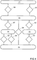
- FIG. 3 shows a flow chart of a method for operating the locking device 2 from FIG Figure 1 with key 5 Figure 2 and the electronic control unit 4 with the locking unit 3 Figure 3 .
- the controller 18 of the control unit 4 communicates with the key controller 11 via the RF interfaces 7, 12.
- the code of the key 5 is read out, the locking unit 3 is activated and the electronic locking mechanism 16 is unlocked or locked. This corresponds to an individual release of the locking unit 3.
- the locking device 2 enables the locking unit 3 to be permanently released.
- the permanent release is switched off, while it is switched on in the activated state Z2.
- the permanent release in the state Z2 is activated in step S1.
- the release and the connection is established via the radio modules 9, 13 between key 5 and Control unit 4.
- the radio modules are connected to one another in step S3, the locking device changes to state Z4.
- the connection is maintained at intervals of, for example, 2 seconds. In these intervals, a check is made as to whether the key 5 is still within the receiving area 8. If it is determined in a step S4 that the key 5 has left the intended area, the controller 18 switches to state Z2 and locks the locking unit 3. The locking unit 3 must then be activated again by presenting a key 5 authorized to lock in step S2 .
- control unit 4 can also be controlled manually by pressing the button 14 on the key 5 in step S6, so that the locking unit 3 is locked in the state Z5, although the key 5 is within the spatial area 8 of the radio module 9 of the Control unit 4 is located. By pressing the button 14 again, the locking unit 3 can be activated and unlocked again in step S5.
- the removal of the key 5 is also monitored in state Z5, so that if the key 5 moves away from the spatial area 8 of the radio module 9 in step S7, the control unit 4 enters state Z2 and the locking unit 3 is locked.
- the permanent release can then be deactivated again in step S8 when the key 5 is presented to the control unit 4 and the button 14 is pressed.
- the button 14 is pressed for a certain period of, for example, three seconds.
Landscapes
- Engineering & Computer Science (AREA)
- Computer Networks & Wireless Communication (AREA)
- Physics & Mathematics (AREA)
- General Physics & Mathematics (AREA)
- Lock And Its Accessories (AREA)
Priority Applications (2)
| Application Number | Priority Date | Filing Date | Title |
|---|---|---|---|
| PL14181878T PL2849159T3 (pl) | 2013-09-11 | 2014-08-22 | Układ zamykania pomieszczenia biurowego lub mieszkalnego i sposób użytkowania takiego układu zamykania |
| SI201431793T SI2849159T1 (sl) | 2013-09-11 | 2014-08-22 | Naprava za zaklepanje pisarne ali bivalnega prostora in postopek za delovanje takšne naprave za zaklepanje |
Applications Claiming Priority (1)
| Application Number | Priority Date | Filing Date | Title |
|---|---|---|---|
| DE102013218215.5A DE102013218215A1 (de) | 2013-09-11 | 2013-09-11 | Schließeinrichtung eines Büro- oder Wohnraums und Verfahren zum Betrieb einer solchen Schließeinrichtung |
Publications (2)
| Publication Number | Publication Date |
|---|---|
| EP2849159A1 EP2849159A1 (de) | 2015-03-18 |
| EP2849159B1 true EP2849159B1 (de) | 2021-02-24 |
Family
ID=51518523
Family Applications (1)
| Application Number | Title | Priority Date | Filing Date |
|---|---|---|---|
| EP14181878.1A Active EP2849159B1 (de) | 2013-09-11 | 2014-08-22 | Schließeinrichtung eines Büro- oder Wohnraums und Verfahren zum Betrieb einer solchen Schließeinrichtung |
Country Status (5)
| Country | Link |
|---|---|
| EP (1) | EP2849159B1 (pl) |
| DE (1) | DE102013218215A1 (pl) |
| ES (1) | ES2859600T3 (pl) |
| PL (1) | PL2849159T3 (pl) |
| SI (1) | SI2849159T1 (pl) |
Family Cites Families (3)
| Publication number | Priority date | Publication date | Assignee | Title |
|---|---|---|---|---|
| DE19912319C1 (de) * | 1999-03-19 | 2000-10-12 | Daimler Chrysler Ag | Elektronische Schließanlage, insbesondere Fahrzeugschließanlage |
| US6634408B2 (en) * | 2001-07-10 | 2003-10-21 | Wesley M. Mays | Automatic barrier operator system |
| WO2011109005A1 (en) | 2010-03-02 | 2011-09-09 | Utc Fire & Security Corporation | Seamless authentication system |
-
2013
- 2013-09-11 DE DE102013218215.5A patent/DE102013218215A1/de not_active Withdrawn
-
2014
- 2014-08-22 ES ES14181878T patent/ES2859600T3/es active Active
- 2014-08-22 EP EP14181878.1A patent/EP2849159B1/de active Active
- 2014-08-22 SI SI201431793T patent/SI2849159T1/sl unknown
- 2014-08-22 PL PL14181878T patent/PL2849159T3/pl unknown
Non-Patent Citations (1)
| Title |
|---|
| None * |
Also Published As
| Publication number | Publication date |
|---|---|
| SI2849159T1 (sl) | 2021-04-30 |
| ES2859600T3 (es) | 2021-10-04 |
| PL2849159T3 (pl) | 2021-07-12 |
| DE102013218215A1 (de) | 2015-03-12 |
| EP2849159A1 (de) | 2015-03-18 |
Similar Documents
| Publication | Publication Date | Title |
|---|---|---|
| EP2428628B1 (de) | System für die Zugangskontrolle und Schliessvorrichtung | |
| EP3077997B1 (de) | Verfahren zum bewirken einer änderung eines betriebsmodus | |
| EP3584770B1 (de) | Verfahren zum betreiben eines schliesssystems, schliesssystem und rohrtresor | |
| DE112016004525T5 (de) | Elektronische Tastatursperre und elektronische Verriegelungssystem für Möbel, Schränke oder Schliessfächer | |
| WO2004023381A1 (de) | Haushaltsgerät mit biometrischer personenidentifikationseinrichtung | |
| DE102012221016A1 (de) | Schließeinheit, Schließvorrichtung und Verfahren zum Entriegeln und/oder Verriegeln eines Schlosses | |
| DE102016002606A1 (de) | Vorrichtung zur Erfassung der Position eines Fenster- oder Türgriffs | |
| EP3479362A1 (de) | SCHLIEßANORDNUNG, INSBESONDERE TÜRSCHLOSSANORDNUNG FÜR EINEN SCHALTSCHRANK UND EIN ENTSPRECHENDES VERFAHREN | |
| DE10114214A1 (de) | Kontrollvorrichtung zur Zugangs-oder Bediennungsberechtigung für Türen oder Fenster | |
| EP2551427A2 (de) | Schlossvorrichtung für Gepäck- und/oder Möbelstücke | |
| EP2350981B1 (de) | Zugangskontroll- und -steuersystem | |
| EP3362997B1 (de) | Abschliessbares behältnis | |
| WO2011100939A1 (de) | Türsicherungssystem | |
| EP2849159B1 (de) | Schließeinrichtung eines Büro- oder Wohnraums und Verfahren zum Betrieb einer solchen Schließeinrichtung | |
| DE102015108027A1 (de) | Schließanlage für eine Gebäudetür | |
| EP3162988B1 (de) | Schliessvorrichtung für eine tür | |
| EP3027827B1 (de) | Elektromagnetisch sperrbarer fenstergriff | |
| EP1338735B1 (de) | Zugangskontrollsystem, -anlage und -verfahren | |
| DE202015008986U1 (de) | Fenster- oder Türgriff mit einer Vorrichtung zur Erfassung der Griffposition | |
| DE102016224995A1 (de) | Fensterbeschlag | |
| DE202020100765U1 (de) | Verriegelungsvorrichtung | |
| EP2955701A2 (de) | Funkgesteuertes elektromechanisches Schließsystem und Verfahren zum Betrieb eines funkgesteuerten elektromechanischen Schließsystems | |
| EP2998462B1 (de) | Fluchtwegsicherungseinrichtung | |
| DE202013104312U1 (de) | RFID-Schlüssel, insbesondere RFID-Transpondereinheit, Programmiervorrichtung und Verriegelungsvorrichtung mit einem RFID-Schloss sowie System daraus | |
| CH700937B1 (de) | Betätigungseinrichtung für Schliessfächer. |
Legal Events
| Date | Code | Title | Description |
|---|---|---|---|
| PUAI | Public reference made under article 153(3) epc to a published international application that has entered the european phase |
Free format text: ORIGINAL CODE: 0009012 |
|
| 17P | Request for examination filed |
Effective date: 20140822 |
|
| AK | Designated contracting states |
Kind code of ref document: A1 Designated state(s): AL AT BE BG CH CY CZ DE DK EE ES FI FR GB GR HR HU IE IS IT LI LT LU LV MC MK MT NL NO PL PT RO RS SE SI SK SM TR |
|
| AX | Request for extension of the european patent |
Extension state: BA ME |
|
| R17P | Request for examination filed (corrected) |
Effective date: 20150730 |
|
| RBV | Designated contracting states (corrected) |
Designated state(s): AL AT BE BG CH CY CZ DE DK EE ES FI FR GB GR HR HU IE IS IT LI LT LU LV MC MK MT NL NO PL PT RO RS SE SI SK SM TR |
|
| 17Q | First examination report despatched |
Effective date: 20160224 |
|
| STAA | Information on the status of an ep patent application or granted ep patent |
Free format text: STATUS: EXAMINATION IS IN PROGRESS |
|
| GRAP | Despatch of communication of intention to grant a patent |
Free format text: ORIGINAL CODE: EPIDOSNIGR1 |
|
| STAA | Information on the status of an ep patent application or granted ep patent |
Free format text: STATUS: GRANT OF PATENT IS INTENDED |
|
| INTG | Intention to grant announced |
Effective date: 20201002 |
|
| GRAS | Grant fee paid |
Free format text: ORIGINAL CODE: EPIDOSNIGR3 |
|
| GRAA | (expected) grant |
Free format text: ORIGINAL CODE: 0009210 |
|
| STAA | Information on the status of an ep patent application or granted ep patent |
Free format text: STATUS: THE PATENT HAS BEEN GRANTED |
|
| AK | Designated contracting states |
Kind code of ref document: B1 Designated state(s): AL AT BE BG CH CY CZ DE DK EE ES FI FR GB GR HR HU IE IS IT LI LT LU LV MC MK MT NL NO PL PT RO RS SE SI SK SM TR |
|
| REG | Reference to a national code |
Ref country code: GB Ref legal event code: FG4D Free format text: NOT ENGLISH |
|
| REG | Reference to a national code |
Ref country code: CH Ref legal event code: EP |
|
| REG | Reference to a national code |
Ref country code: DE Ref legal event code: R096 Ref document number: 502014015288 Country of ref document: DE |
|
| REG | Reference to a national code |
Ref country code: AT Ref legal event code: REF Ref document number: 1365458 Country of ref document: AT Kind code of ref document: T Effective date: 20210315 Ref country code: CH Ref legal event code: NV Representative=s name: VALIPAT S.A. C/O BOVARD SA NEUCHATEL, CH |
|
| REG | Reference to a national code |
Ref country code: IE Ref legal event code: FG4D Free format text: LANGUAGE OF EP DOCUMENT: GERMAN |
|
| REG | Reference to a national code |
Ref country code: RO Ref legal event code: EPE |
|
| REG | Reference to a national code |
Ref country code: NL Ref legal event code: FP |
|
| REG | Reference to a national code |
Ref country code: GR Ref legal event code: EP Ref document number: 20210400791 Country of ref document: GR Effective date: 20210519 |
|
| REG | Reference to a national code |
Ref country code: LT Ref legal event code: MG9D |
|
| PG25 | Lapsed in a contracting state [announced via postgrant information from national office to epo] |
Ref country code: HR Free format text: LAPSE BECAUSE OF FAILURE TO SUBMIT A TRANSLATION OF THE DESCRIPTION OR TO PAY THE FEE WITHIN THE PRESCRIBED TIME-LIMIT Effective date: 20210224 Ref country code: FI Free format text: LAPSE BECAUSE OF FAILURE TO SUBMIT A TRANSLATION OF THE DESCRIPTION OR TO PAY THE FEE WITHIN THE PRESCRIBED TIME-LIMIT Effective date: 20210224 Ref country code: PT Free format text: LAPSE BECAUSE OF FAILURE TO SUBMIT A TRANSLATION OF THE DESCRIPTION OR TO PAY THE FEE WITHIN THE PRESCRIBED TIME-LIMIT Effective date: 20210624 Ref country code: LT Free format text: LAPSE BECAUSE OF FAILURE TO SUBMIT A TRANSLATION OF THE DESCRIPTION OR TO PAY THE FEE WITHIN THE PRESCRIBED TIME-LIMIT Effective date: 20210224 Ref country code: BG Free format text: LAPSE BECAUSE OF FAILURE TO SUBMIT A TRANSLATION OF THE DESCRIPTION OR TO PAY THE FEE WITHIN THE PRESCRIBED TIME-LIMIT Effective date: 20210524 Ref country code: NO Free format text: LAPSE BECAUSE OF FAILURE TO SUBMIT A TRANSLATION OF THE DESCRIPTION OR TO PAY THE FEE WITHIN THE PRESCRIBED TIME-LIMIT Effective date: 20210524 |
|
| PG25 | Lapsed in a contracting state [announced via postgrant information from national office to epo] |
Ref country code: SE Free format text: LAPSE BECAUSE OF FAILURE TO SUBMIT A TRANSLATION OF THE DESCRIPTION OR TO PAY THE FEE WITHIN THE PRESCRIBED TIME-LIMIT Effective date: 20210224 Ref country code: RS Free format text: LAPSE BECAUSE OF FAILURE TO SUBMIT A TRANSLATION OF THE DESCRIPTION OR TO PAY THE FEE WITHIN THE PRESCRIBED TIME-LIMIT Effective date: 20210224 Ref country code: LV Free format text: LAPSE BECAUSE OF FAILURE TO SUBMIT A TRANSLATION OF THE DESCRIPTION OR TO PAY THE FEE WITHIN THE PRESCRIBED TIME-LIMIT Effective date: 20210224 |
|
| PG25 | Lapsed in a contracting state [announced via postgrant information from national office to epo] |
Ref country code: IS Free format text: LAPSE BECAUSE OF FAILURE TO SUBMIT A TRANSLATION OF THE DESCRIPTION OR TO PAY THE FEE WITHIN THE PRESCRIBED TIME-LIMIT Effective date: 20210624 |
|
| REG | Reference to a national code |
Ref country code: ES Ref legal event code: FG2A Ref document number: 2859600 Country of ref document: ES Kind code of ref document: T3 Effective date: 20211004 |
|
| PG25 | Lapsed in a contracting state [announced via postgrant information from national office to epo] |
Ref country code: SM Free format text: LAPSE BECAUSE OF FAILURE TO SUBMIT A TRANSLATION OF THE DESCRIPTION OR TO PAY THE FEE WITHIN THE PRESCRIBED TIME-LIMIT Effective date: 20210224 Ref country code: EE Free format text: LAPSE BECAUSE OF FAILURE TO SUBMIT A TRANSLATION OF THE DESCRIPTION OR TO PAY THE FEE WITHIN THE PRESCRIBED TIME-LIMIT Effective date: 20210224 |
|
| REG | Reference to a national code |
Ref country code: DE Ref legal event code: R097 Ref document number: 502014015288 Country of ref document: DE |
|
| PG25 | Lapsed in a contracting state [announced via postgrant information from national office to epo] |
Ref country code: SK Free format text: LAPSE BECAUSE OF FAILURE TO SUBMIT A TRANSLATION OF THE DESCRIPTION OR TO PAY THE FEE WITHIN THE PRESCRIBED TIME-LIMIT Effective date: 20210224 Ref country code: DK Free format text: LAPSE BECAUSE OF FAILURE TO SUBMIT A TRANSLATION OF THE DESCRIPTION OR TO PAY THE FEE WITHIN THE PRESCRIBED TIME-LIMIT Effective date: 20210224 |
|
| PLBE | No opposition filed within time limit |
Free format text: ORIGINAL CODE: 0009261 |
|
| STAA | Information on the status of an ep patent application or granted ep patent |
Free format text: STATUS: NO OPPOSITION FILED WITHIN TIME LIMIT |
|
| PG25 | Lapsed in a contracting state [announced via postgrant information from national office to epo] |
Ref country code: AL Free format text: LAPSE BECAUSE OF FAILURE TO SUBMIT A TRANSLATION OF THE DESCRIPTION OR TO PAY THE FEE WITHIN THE PRESCRIBED TIME-LIMIT Effective date: 20210224 |
|
| 26N | No opposition filed |
Effective date: 20211125 |
|
| PG25 | Lapsed in a contracting state [announced via postgrant information from national office to epo] |
Ref country code: MC Free format text: LAPSE BECAUSE OF FAILURE TO SUBMIT A TRANSLATION OF THE DESCRIPTION OR TO PAY THE FEE WITHIN THE PRESCRIBED TIME-LIMIT Effective date: 20210224 |
|
| PG25 | Lapsed in a contracting state [announced via postgrant information from national office to epo] |
Ref country code: IS Free format text: LAPSE BECAUSE OF FAILURE TO SUBMIT A TRANSLATION OF THE DESCRIPTION OR TO PAY THE FEE WITHIN THE PRESCRIBED TIME-LIMIT Effective date: 20210624 Ref country code: LU Free format text: LAPSE BECAUSE OF NON-PAYMENT OF DUE FEES Effective date: 20210822 |
|
| PG25 | Lapsed in a contracting state [announced via postgrant information from national office to epo] |
Ref country code: IE Free format text: LAPSE BECAUSE OF NON-PAYMENT OF DUE FEES Effective date: 20210822 |
|
| PG25 | Lapsed in a contracting state [announced via postgrant information from national office to epo] |
Ref country code: HU Free format text: LAPSE BECAUSE OF FAILURE TO SUBMIT A TRANSLATION OF THE DESCRIPTION OR TO PAY THE FEE WITHIN THE PRESCRIBED TIME-LIMIT; INVALID AB INITIO Effective date: 20140822 |
|
| P01 | Opt-out of the competence of the unified patent court (upc) registered |
Effective date: 20230515 |
|
| PG25 | Lapsed in a contracting state [announced via postgrant information from national office to epo] |
Ref country code: CY Free format text: LAPSE BECAUSE OF FAILURE TO SUBMIT A TRANSLATION OF THE DESCRIPTION OR TO PAY THE FEE WITHIN THE PRESCRIBED TIME-LIMIT Effective date: 20210224 |
|
| PG25 | Lapsed in a contracting state [announced via postgrant information from national office to epo] |
Ref country code: MK Free format text: LAPSE BECAUSE OF FAILURE TO SUBMIT A TRANSLATION OF THE DESCRIPTION OR TO PAY THE FEE WITHIN THE PRESCRIBED TIME-LIMIT Effective date: 20210224 |
|
| PG25 | Lapsed in a contracting state [announced via postgrant information from national office to epo] |
Ref country code: MT Free format text: LAPSE BECAUSE OF FAILURE TO SUBMIT A TRANSLATION OF THE DESCRIPTION OR TO PAY THE FEE WITHIN THE PRESCRIBED TIME-LIMIT Effective date: 20210224 |
|
| PGFP | Annual fee paid to national office [announced via postgrant information from national office to epo] |
Ref country code: GR Payment date: 20240819 Year of fee payment: 11 |
|
| PGFP | Annual fee paid to national office [announced via postgrant information from national office to epo] |
Ref country code: CH Payment date: 20240901 Year of fee payment: 11 |
|
| PGFP | Annual fee paid to national office [announced via postgrant information from national office to epo] |
Ref country code: CZ Payment date: 20240809 Year of fee payment: 11 |
|
| PGFP | Annual fee paid to national office [announced via postgrant information from national office to epo] |
Ref country code: PL Payment date: 20240813 Year of fee payment: 11 |
|
| PGFP | Annual fee paid to national office [announced via postgrant information from national office to epo] |
Ref country code: SI Payment date: 20240812 Year of fee payment: 11 |
|
| PGFP | Annual fee paid to national office [announced via postgrant information from national office to epo] |
Ref country code: RO Payment date: 20240820 Year of fee payment: 11 |
|
| REG | Reference to a national code |
Ref country code: DE Ref legal event code: R081 Ref document number: 502014015288 Country of ref document: DE Owner name: AUG. WINKHAUS SE & CO. KG, DE Free format text: FORMER OWNER: AUG. WINKHAUS GMBH & CO. KG, 48291 TELGTE, DE Ref country code: DE Ref legal event code: R081 Ref document number: 502014015288 Country of ref document: DE Owner name: AUG. WINKHAUS SE, DE Free format text: FORMER OWNER: AUG. WINKHAUS GMBH & CO. KG, 48291 TELGTE, DE |
|
| REG | Reference to a national code |
Ref country code: DE Ref legal event code: R081 Ref document number: 502014015288 Country of ref document: DE Owner name: AUG. WINKHAUS SE, DE Free format text: FORMER OWNER: AUG. WINKHAUS SE & CO. KG, 48291 TELGTE, DE |
|
| PGFP | Annual fee paid to national office [announced via postgrant information from national office to epo] |
Ref country code: NL Payment date: 20250821 Year of fee payment: 12 |
|
| PGFP | Annual fee paid to national office [announced via postgrant information from national office to epo] |
Ref country code: ES Payment date: 20250917 Year of fee payment: 12 |
|
| PGFP | Annual fee paid to national office [announced via postgrant information from national office to epo] |
Ref country code: DE Payment date: 20250819 Year of fee payment: 12 |
|
| PGFP | Annual fee paid to national office [announced via postgrant information from national office to epo] |
Ref country code: IT Payment date: 20250829 Year of fee payment: 12 |
|
| PGFP | Annual fee paid to national office [announced via postgrant information from national office to epo] |
Ref country code: BE Payment date: 20250820 Year of fee payment: 12 Ref country code: GB Payment date: 20250822 Year of fee payment: 12 |
|
| PGFP | Annual fee paid to national office [announced via postgrant information from national office to epo] |
Ref country code: AT Payment date: 20250819 Year of fee payment: 12 Ref country code: FR Payment date: 20250821 Year of fee payment: 12 |
|
| PG25 | Lapsed in a contracting state [announced via postgrant information from national office to epo] |
Ref country code: TR Free format text: LAPSE BECAUSE OF FAILURE TO SUBMIT A TRANSLATION OF THE DESCRIPTION OR TO PAY THE FEE WITHIN THE PRESCRIBED TIME-LIMIT Effective date: 20210224 |
|
| REG | Reference to a national code |
Ref country code: CH Ref legal event code: H13 Free format text: ST27 STATUS EVENT CODE: U-0-0-H10-H13 (AS PROVIDED BY THE NATIONAL OFFICE) Effective date: 20260324 |
|
| PG25 | Lapsed in a contracting state [announced via postgrant information from national office to epo] |
Ref country code: RO Free format text: LAPSE BECAUSE OF NON-PAYMENT OF DUE FEES Effective date: 20250822 |
|
| PG25 | Lapsed in a contracting state [announced via postgrant information from national office to epo] |
Ref country code: CH Free format text: LAPSE BECAUSE OF NON-PAYMENT OF DUE FEES Effective date: 20250831 Ref country code: CZ Free format text: LAPSE BECAUSE OF NON-PAYMENT OF DUE FEES Effective date: 20250822 |
|
| PG25 | Lapsed in a contracting state [announced via postgrant information from national office to epo] |
Ref country code: GR Free format text: LAPSE BECAUSE OF NON-PAYMENT OF DUE FEES Effective date: 20260309 |